CC and C Technologies WA2204A 802.11b/g WLAN Router User Manual WBR G UMv1 1 En
CC&C; Technologies, Inc. 802.11b/g WLAN Router WBR G UMv1 1 En
UserManual.wiki
>
CC and C Technologies
>
WA2204A User Manual
User Manual
Navigation menu
Upload a User Manual
Namespaces
Wiki Guide
HTML
PDF
Info
Views
User Manual
Discussion / Help
Navigation


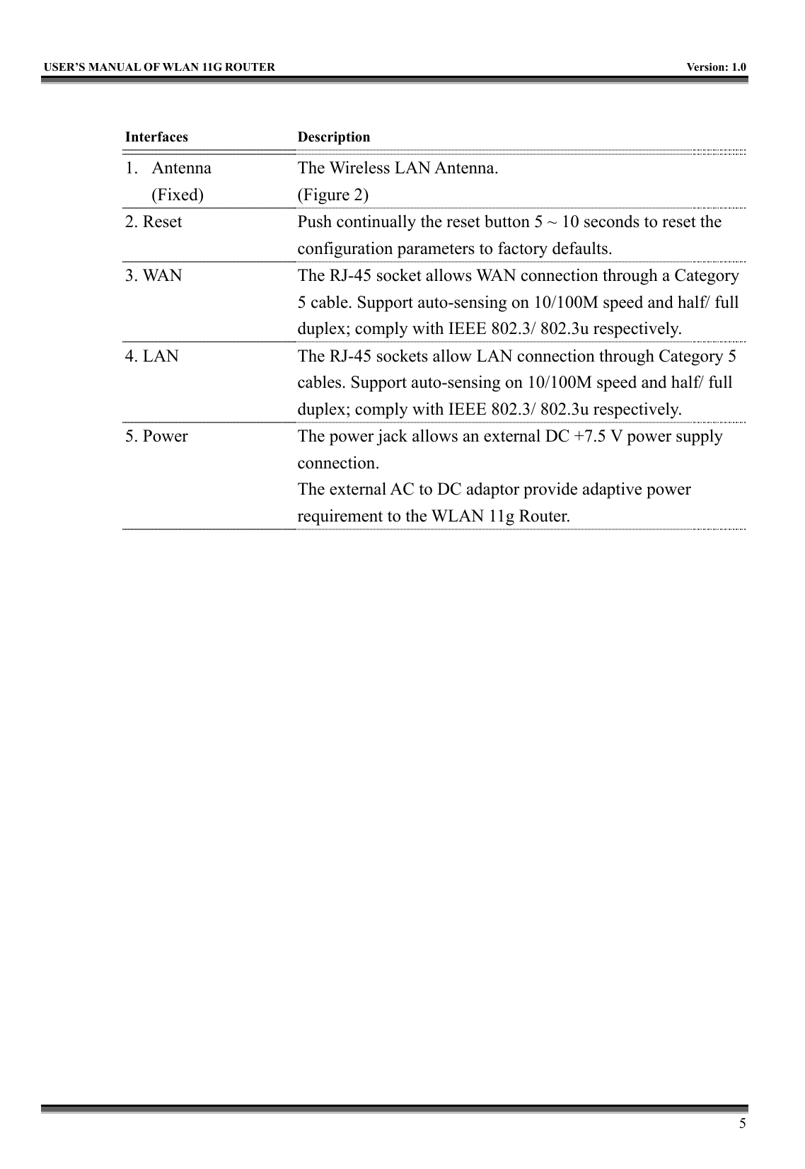
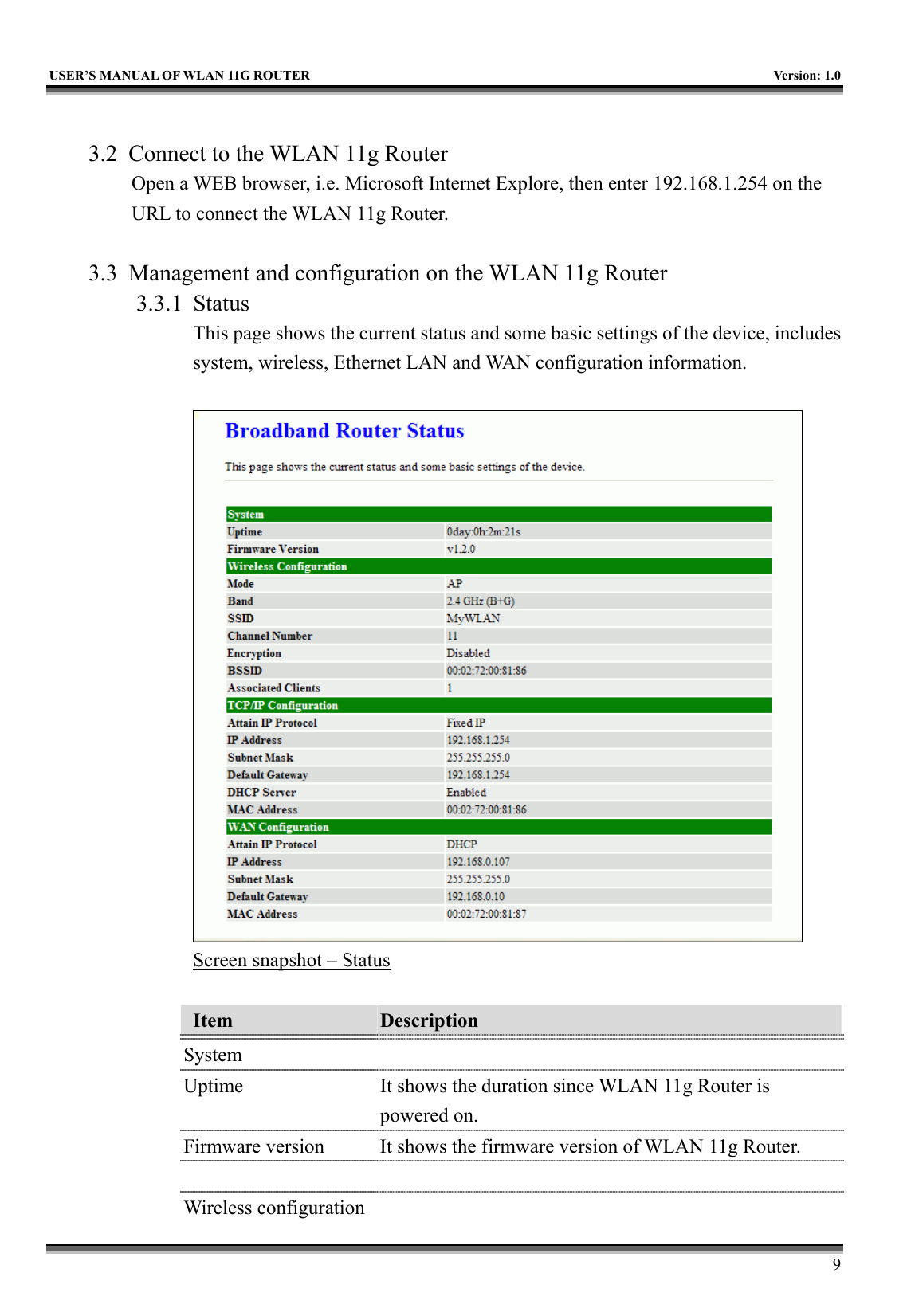
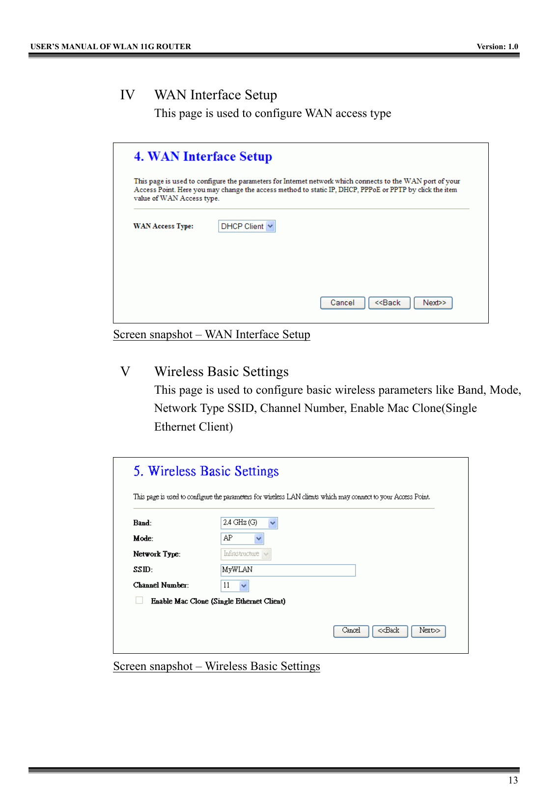
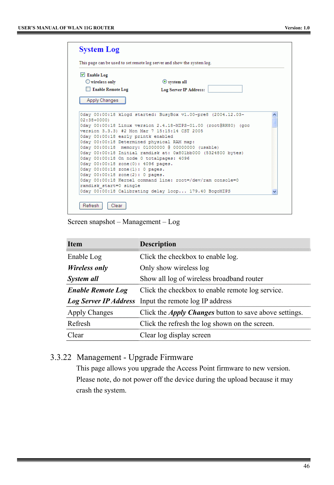
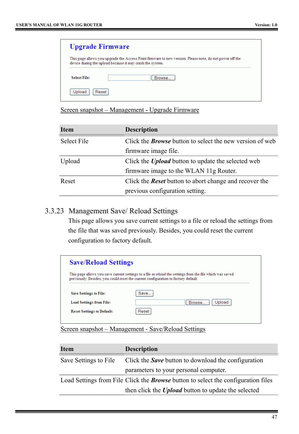
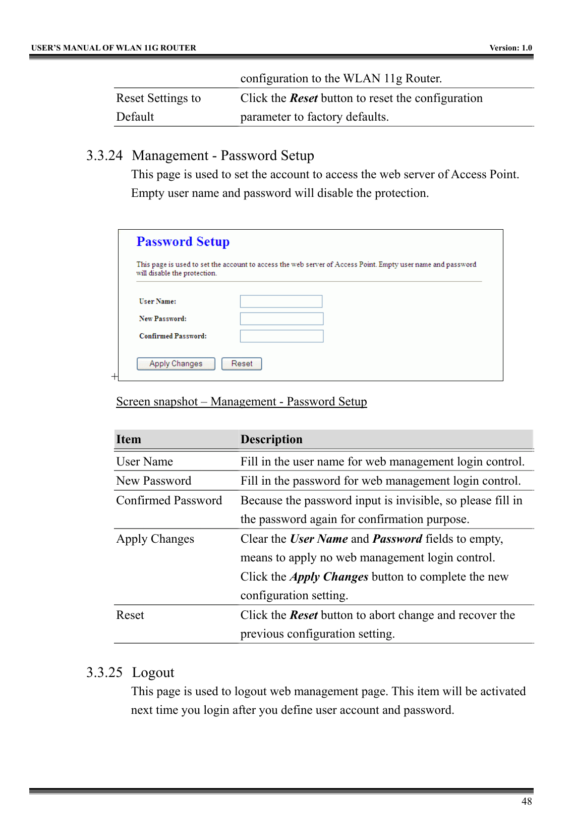
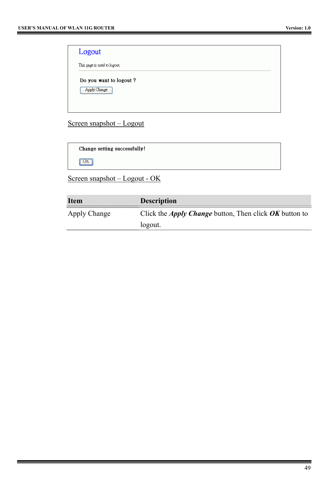
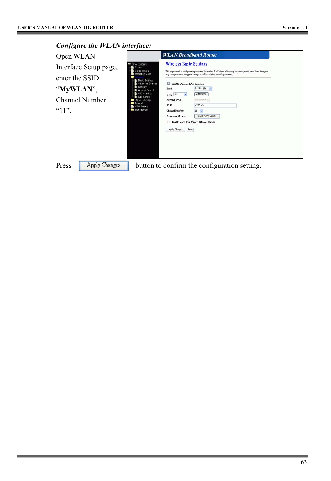
![USER’S MANUAL OF WLAN 11G ROUTER Version: 1.0 16 Mode Click to select the WLAN AP / Client / WDS / AP+WDS wireless mode. Site Survey The Site Survey button provides tool to scan the wireless network. If any Access Point or IBSS is found, you could choose to connect it manually when client mode is enabled. Refer to 3.3.9 Site Survey. SSID It is the wireless network name. The SSID can be 32 bytes long. Channel Number Select the wireless communication channel from pull-down menu. Associated Clients Click the Show Active Clients button to open Active Wireless Client Table that shows the MAC address, transmit-packet, receive-packet and transmission-rate for each associated wireless client. Enable Mac Clone (Single Ethernet Client)Take Laptop NIC MAC address as wireless client MAC address. [Client Mode only] Apply Changes Click the Apply Changes button to complete the new configuration setting. Reset Click the Reset button to abort change and recover the previous configuration setting. 3.3.5 Wireless - Advanced Settings These settings are only for more technically advanced users who have a sufficient knowledge about wireless LAN. These settings should not be changed unless you know what effect the changes will have on your WLAN 11g Router.](https://usermanual.wiki/CC-and-C-Technologies/WA2204A/User-Guide-571605-Page-28.png)
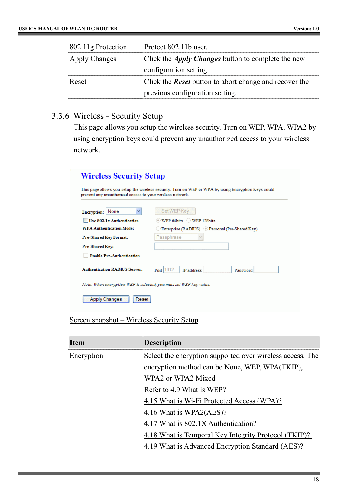
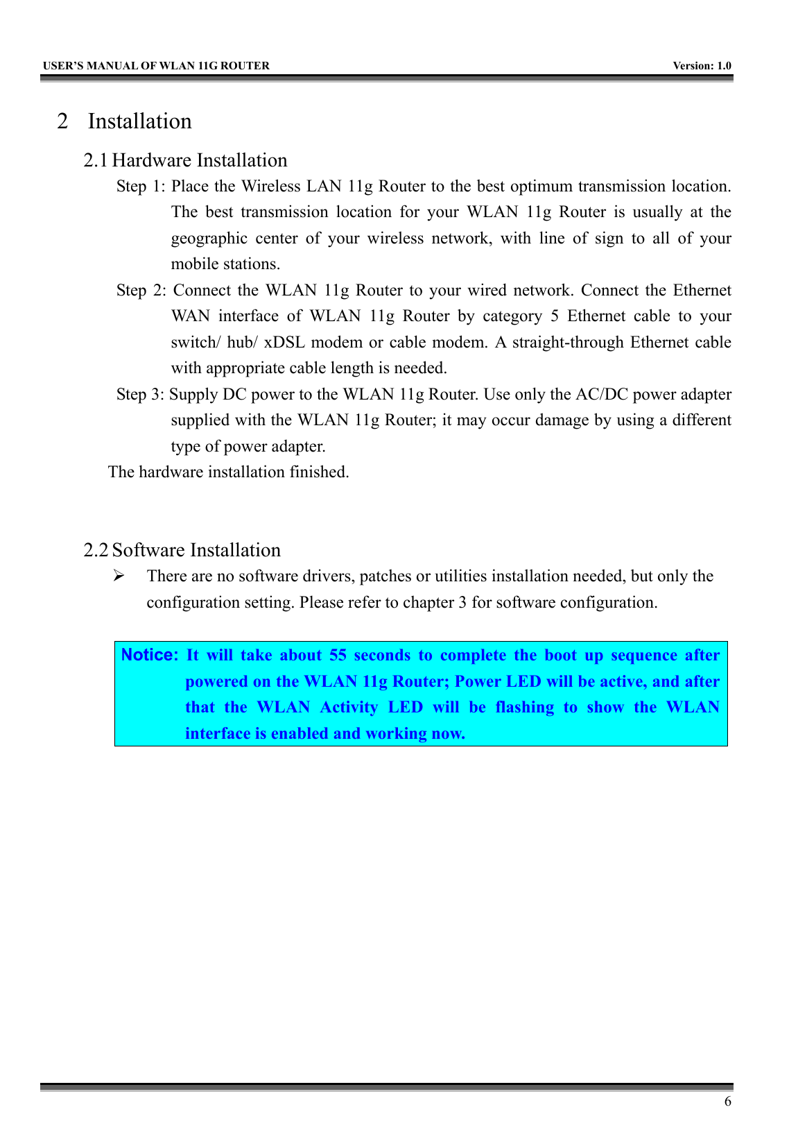
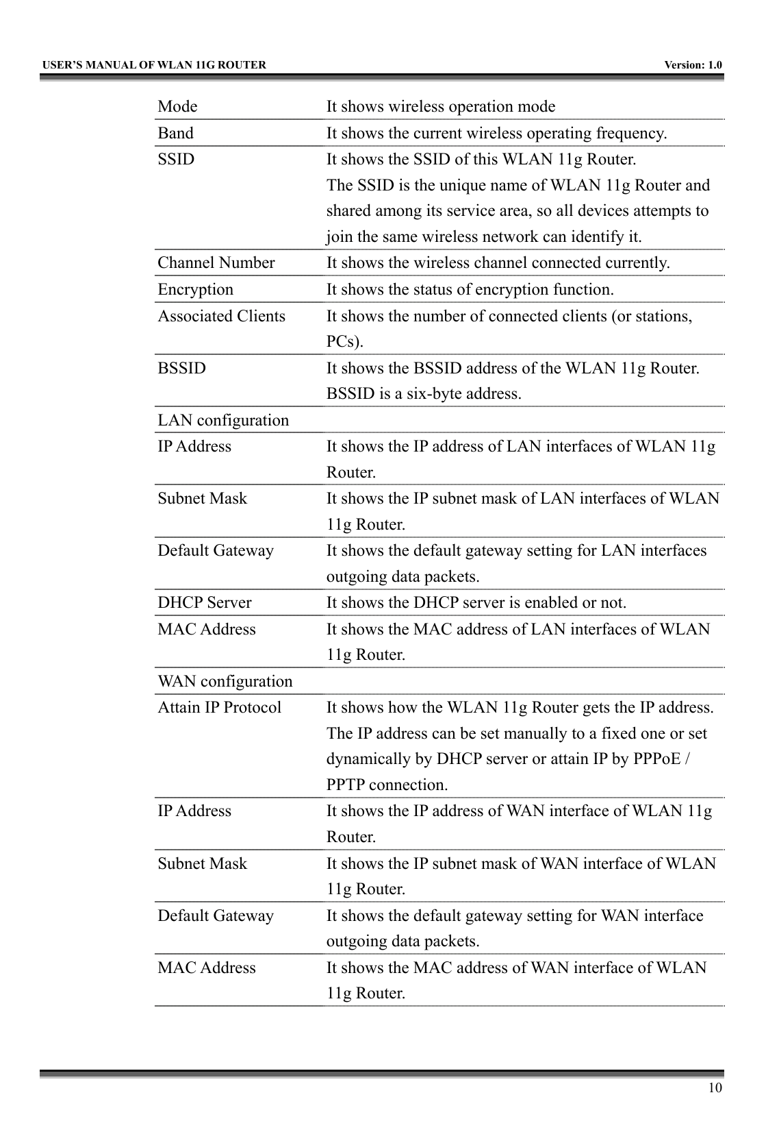
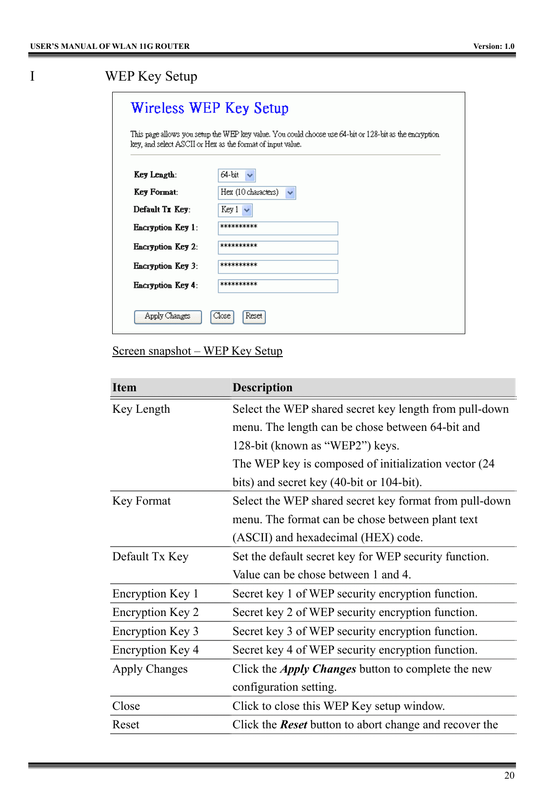
![USER’S MANUAL OF WLAN 11G ROUTER Version: 1.0 19 Use 802.1x Authentication While Encryption is selected to be WEP. Click the check box to enable IEEE 802.1x authentication function. Refer to 4.16 What is 802.1x Authentication? WPA Authentication Mode While Encryption is selected to be WPA. Click to select the WPA Authentication Mode with Enterprise (RADIUS) or Personal (Pre-Shared Key). Refer to 4.15 What is Wi-Fi Protected Access (WPA)? Pre-Shared Key Format While Encryption is selected to be WPA. Select the Pre-shared key format from the pull-down menu. The format can be Passphrase or Hex (64 characters). [WPA, Personal(Pre-Shared Key) only] Pre-Shared Key Fill in the key value. [WPA, Personal(Pre-Shared Key) only] Enable Pre-Authentication Click to enable Pre-Authentication. [WPA2/WPA2 Mixed only, Enterprise only] Authentication RADIUS Server Set the IP address, port and login password information of authentication RADIUS sever. Apply Changes Click the Apply Changes button to complete the new configuration setting. Reset Click the Reset button to abort change and recover the previous configuration setting.](https://usermanual.wiki/CC-and-C-Technologies/WA2204A/User-Guide-571605-Page-31.png)
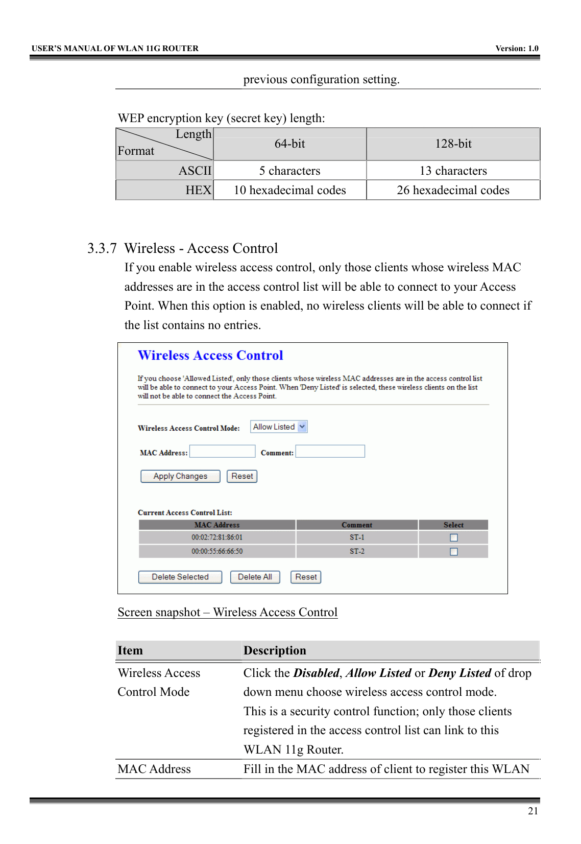
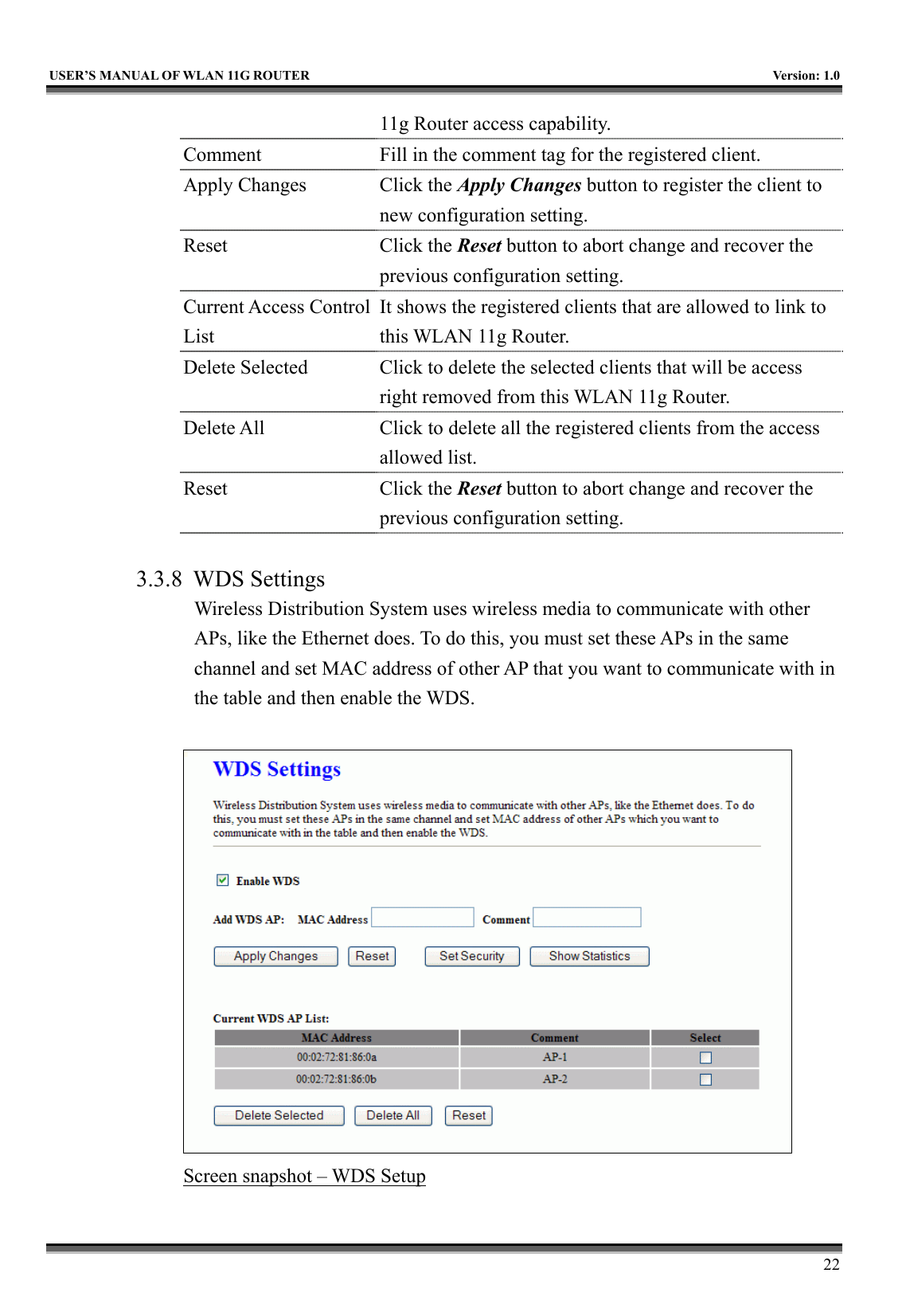
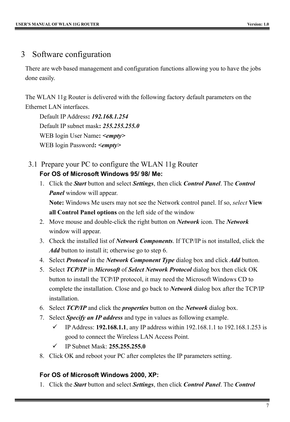
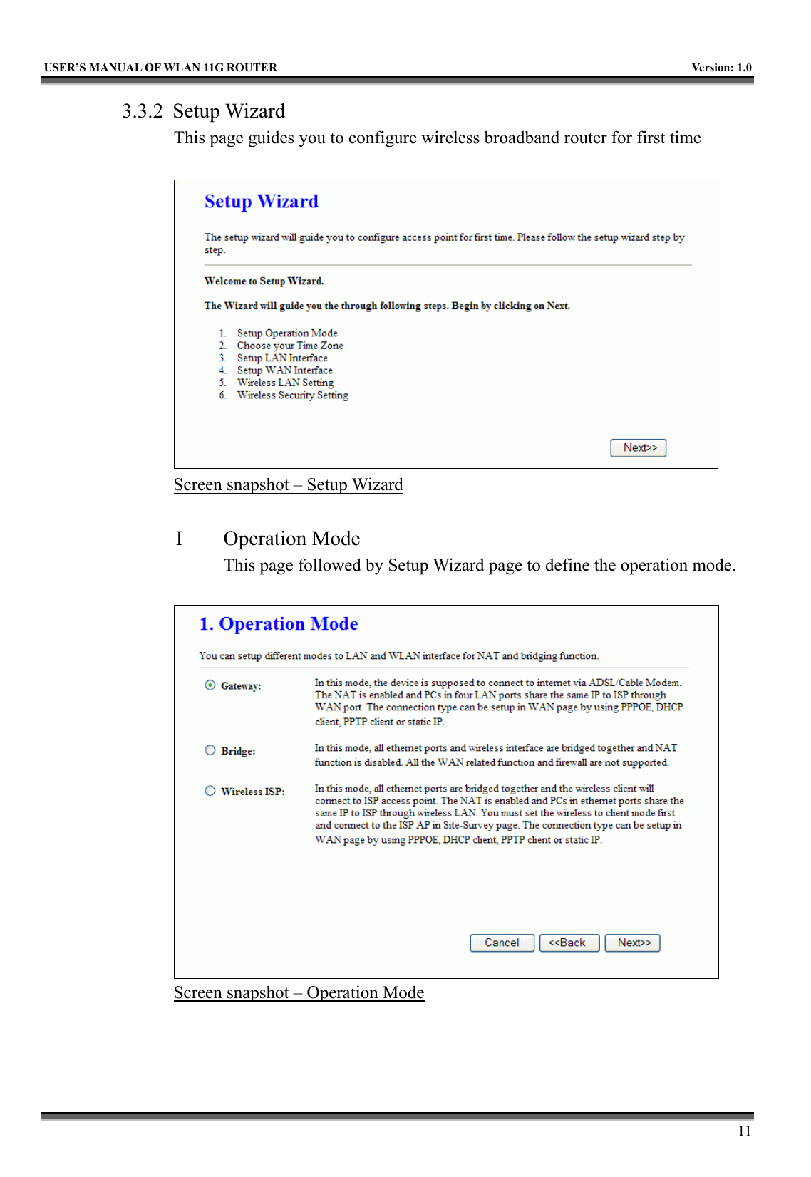
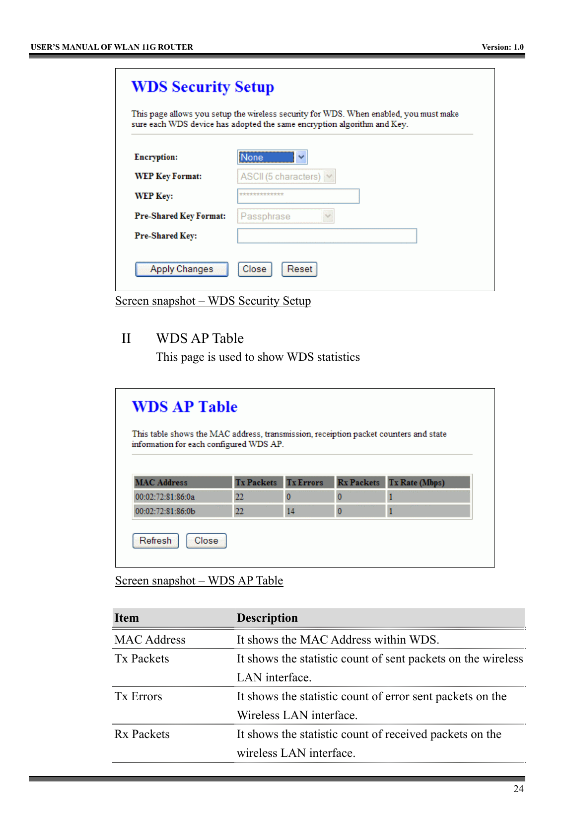
![USER’S MANUAL OF WLAN 11G ROUTER Version: 1.0 23 Item Description Enable WDS Click the check box to enable wireless distribution system. Refer to 4.21 What is Wireless Distribution System (WDS)? MAC Address Fill in the MAC address of AP to register the wireless distribution system access capability. Comment Fill in the comment tag for the registered AP. Apply Changes Click the Apply Changes button to register the AP to new configuration setting. Reset Click the Reset button to abort change and recover the previous configuration setting. Set Security Click button to configure wireless security like WEP(64bits), WEP(128bits), WPA(TKIP), WPA2(AES) or None Show Statistics It shows the TX, RX packets, rate statistics Delete Selected Click to delete the selected clients that will be removed from the wireless distribution system. Delete All Click to delete all the registered APs from the wireless distribution system allowed list. Reset Click the Reset button to abort change and recover the previous configuration setting. I WDS Security Setup Requirement: Set [Wireless]->[Basic Settings]->[Mode]->AP+WDS This page is used to configure the wireless security between APs. Refer to 3.3.6 Wireless Security Setup.](https://usermanual.wiki/CC-and-C-Technologies/WA2204A/User-Guide-571605-Page-35.png)
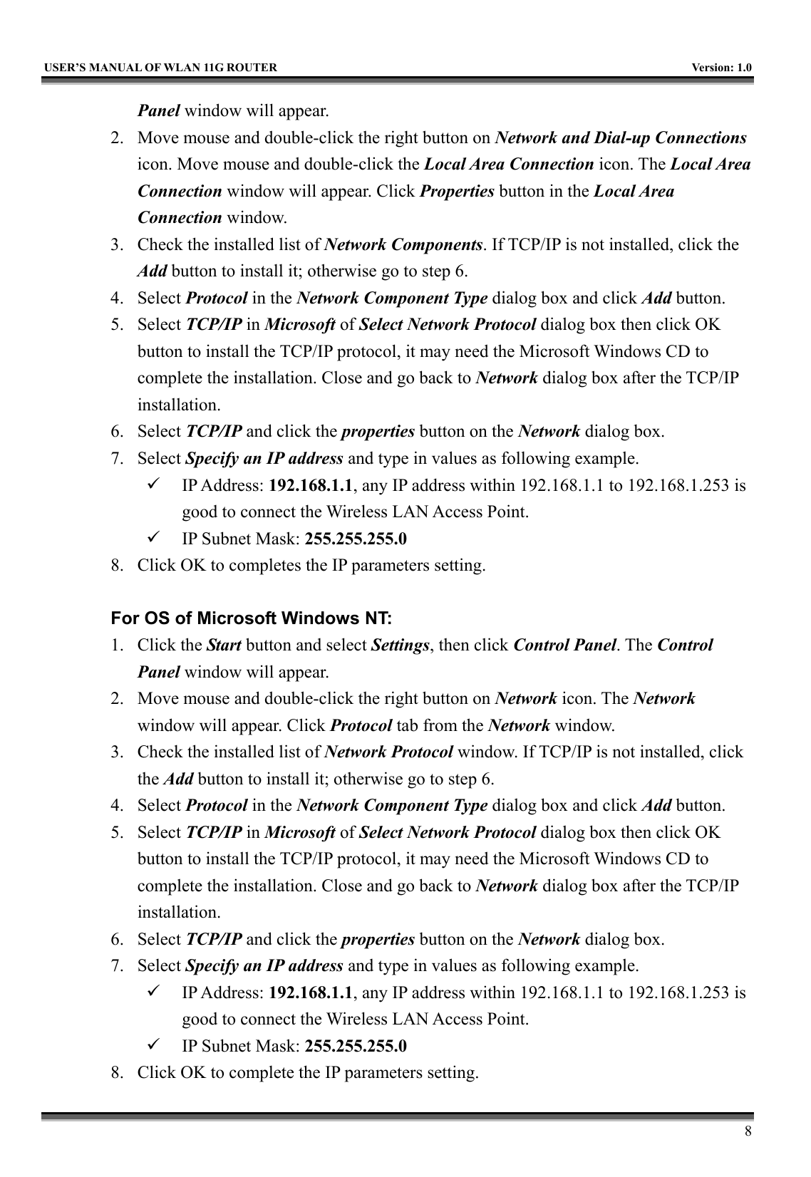
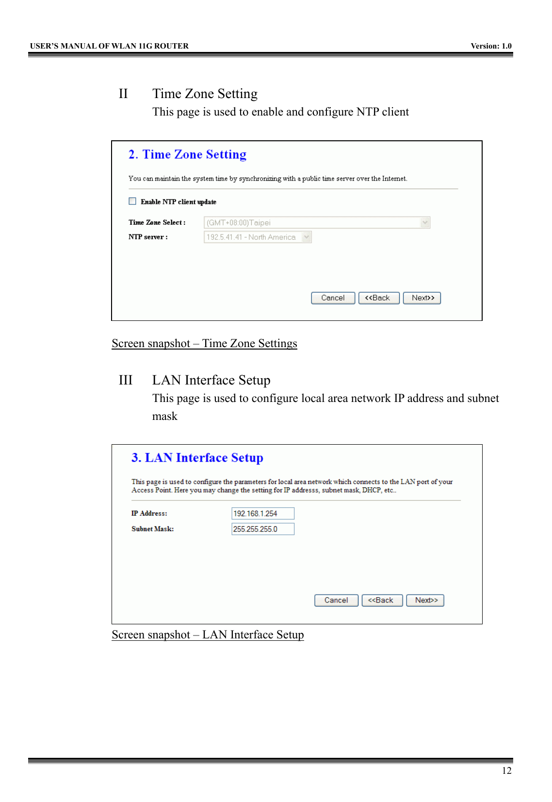
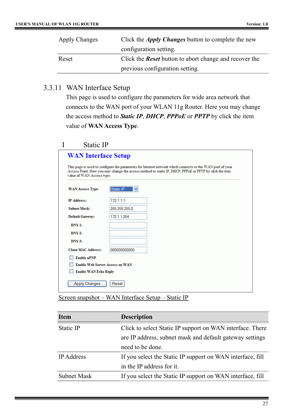
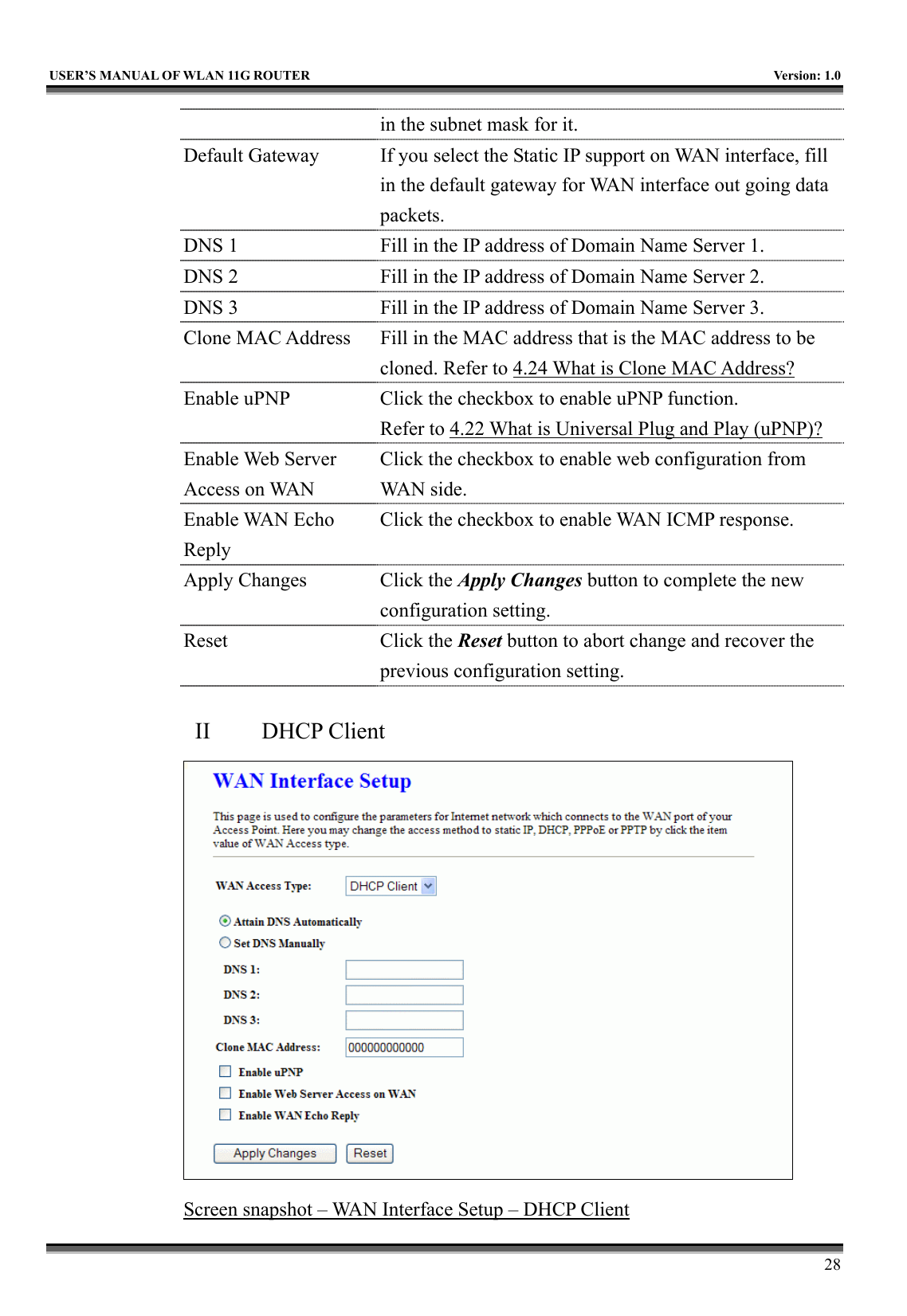
![USER’S MANUAL OF WLAN 11G ROUTER Version: 1.0 26 the setting for IP address, subnet mask, DHCP, etc. Screen snapshot – LAN Interface Setup Item Description IP Address Fill in the IP address of LAN interfaces of this WLAN 11g Router. Subnet Mask Fill in the subnet mask of LAN interfaces of this WLAN 11g Router. Default Gateway Fill in the default gateway for LAN interfaces out going data packets. DHCP Server Click to select Disabled, Client or Server in different operation mode of wireless broadband router. DHCP Client Range Fill in the start IP address and end IP address to allocate a range of IP addresses; client with DHCP function set will be assigned an IP address from the range. Show Client Click to open the Active DHCP Client Table window that shows the active clients with their assigned IP address, MAC address and time expired information. [Server mode only] 802.1d Spanning Tree Select to enable or disable the IEEE 802.1d Spanning Tree function from pull-down menu. Clone MAC Address Fill in the MAC address that is the MAC address to be cloned. Refer to 4.24 What is Clone MAC Address?](https://usermanual.wiki/CC-and-C-Technologies/WA2204A/User-Guide-571605-Page-38.png)
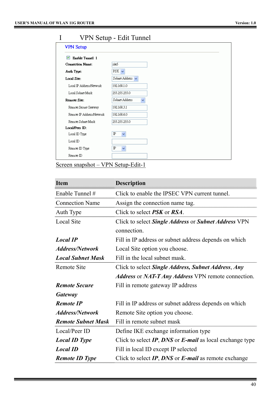
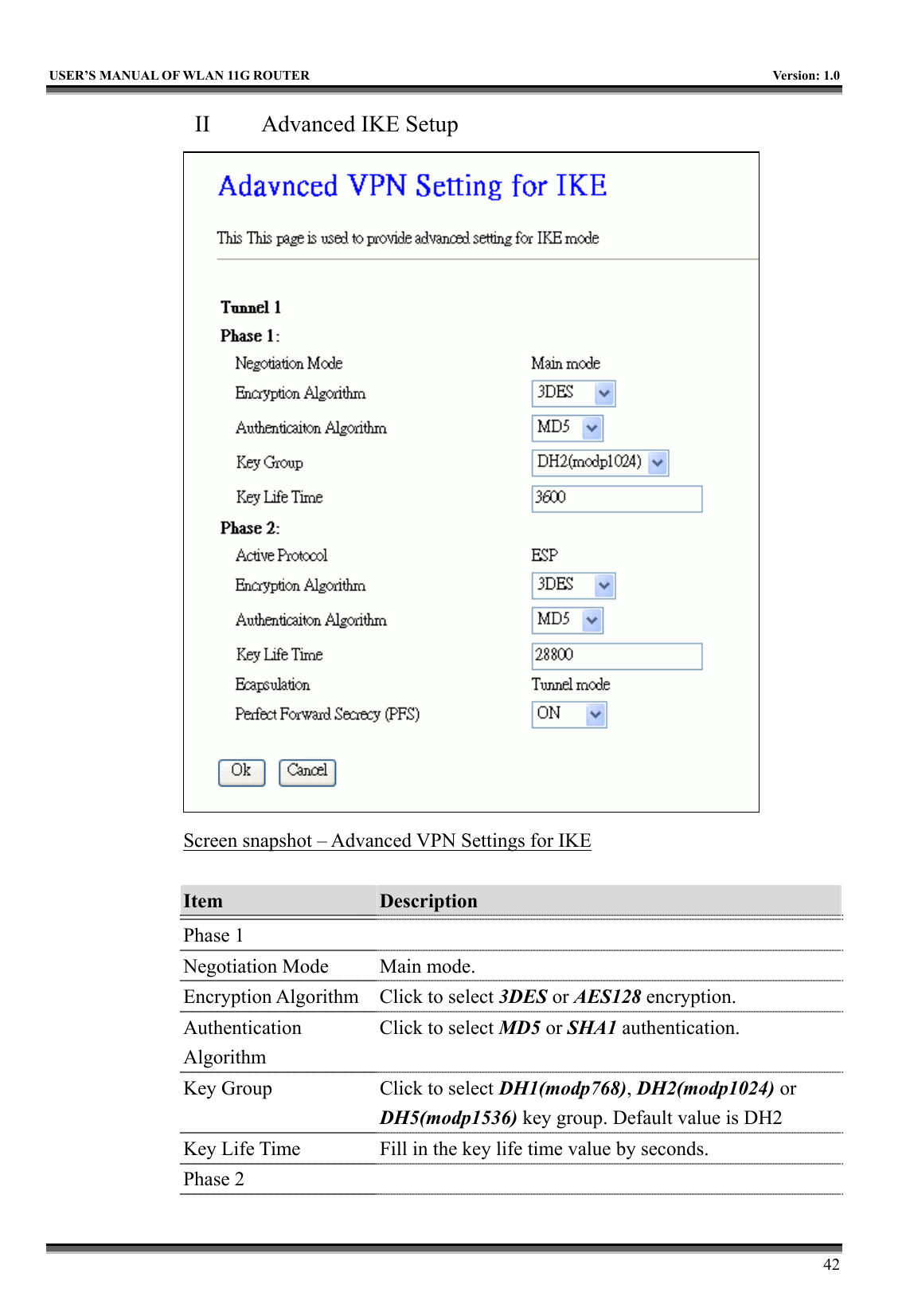
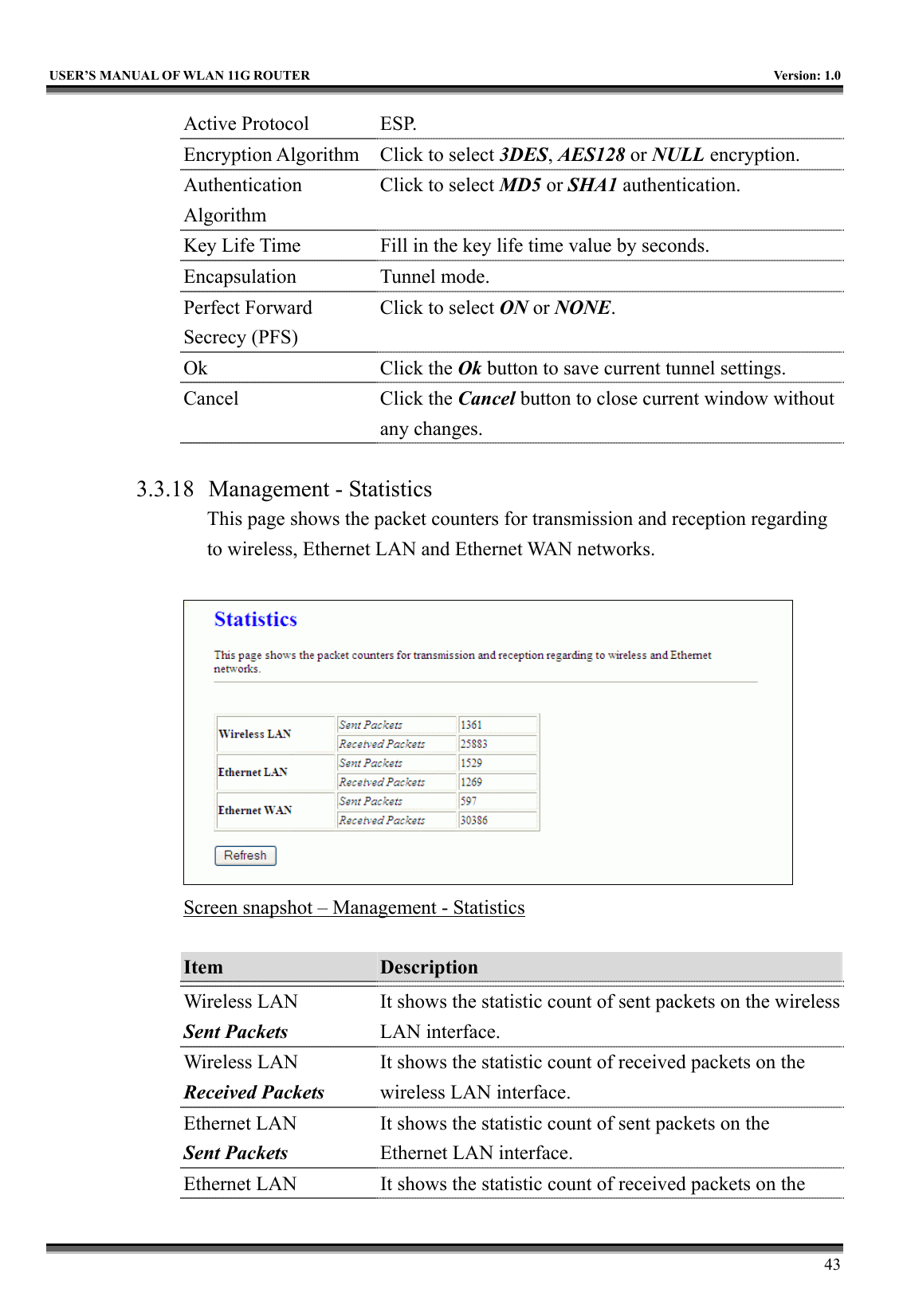
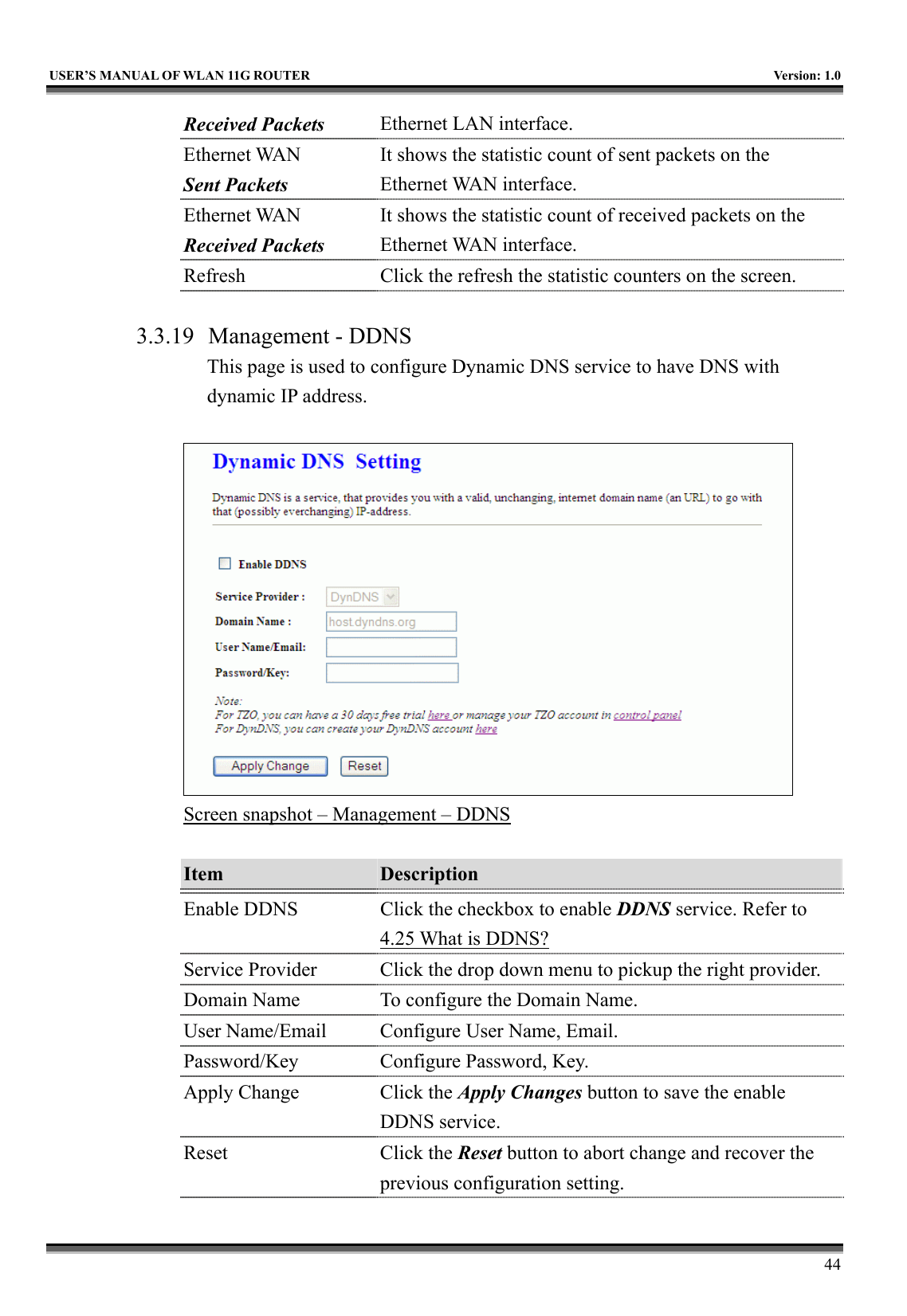
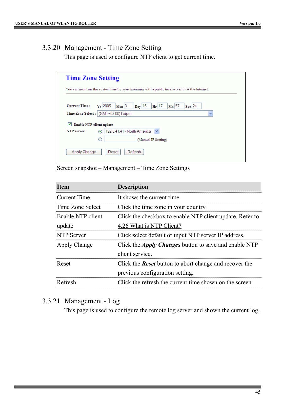
![USER’S MANUAL OF WLAN 11G ROUTER Version: 1.0 41 Remote ID type Fill in remote ID except IP selected Screen snapshot – VPN Setup-Edit-2 Item Description Key Management Click to select IKE or Manual mode. Advanced Click Advanced button to configure more IKE settings. Connection Type Click to select Initiator or Responder mode. Connect Click to connect manually. [Responder mode only] Disconnect Click to disconnect manually. [Responder mode only]. ESP Click to configure 3DES, AES128 or NULL encryption.Click to configure MD5 or SHA1 authentication. PreShared Key Fill in the key value. [IKE mode only] Remote RSA Key Fill in the remote gateway RSA key. [IKE mode only] Status It shows connection status. [IKE mode only] SPI Fill in Security Parameter Index value. [Manual mode only] Encryption Key Fill in encryption key. [Manual mode only] Authentication Key Fill in authentication key. [Manual mode only] Apply Change Click the Apply Changes button to save current tunnel settings. Reset Click the Reset button to abort change and recover the previous configuration setting. Refresh It shows the current connection status. [Manual mode only] Back It returns back to VPN Setup page.](https://usermanual.wiki/CC-and-C-Technologies/WA2204A/User-Guide-571605-Page-53.png)