CC and C Technologies WA6212 WLAN 11n Router User Manual User s Manual
CC&C; Technologies, Inc. WLAN 11n Router User s Manual
UserManual.wiki
>
CC and C Technologies
>
WA6212 User Manual
manual
Navigation menu
Upload a User Manual
Namespaces
Wiki Guide
HTML
PDF
Info
Views
User Manual
Discussion / Help
Navigation
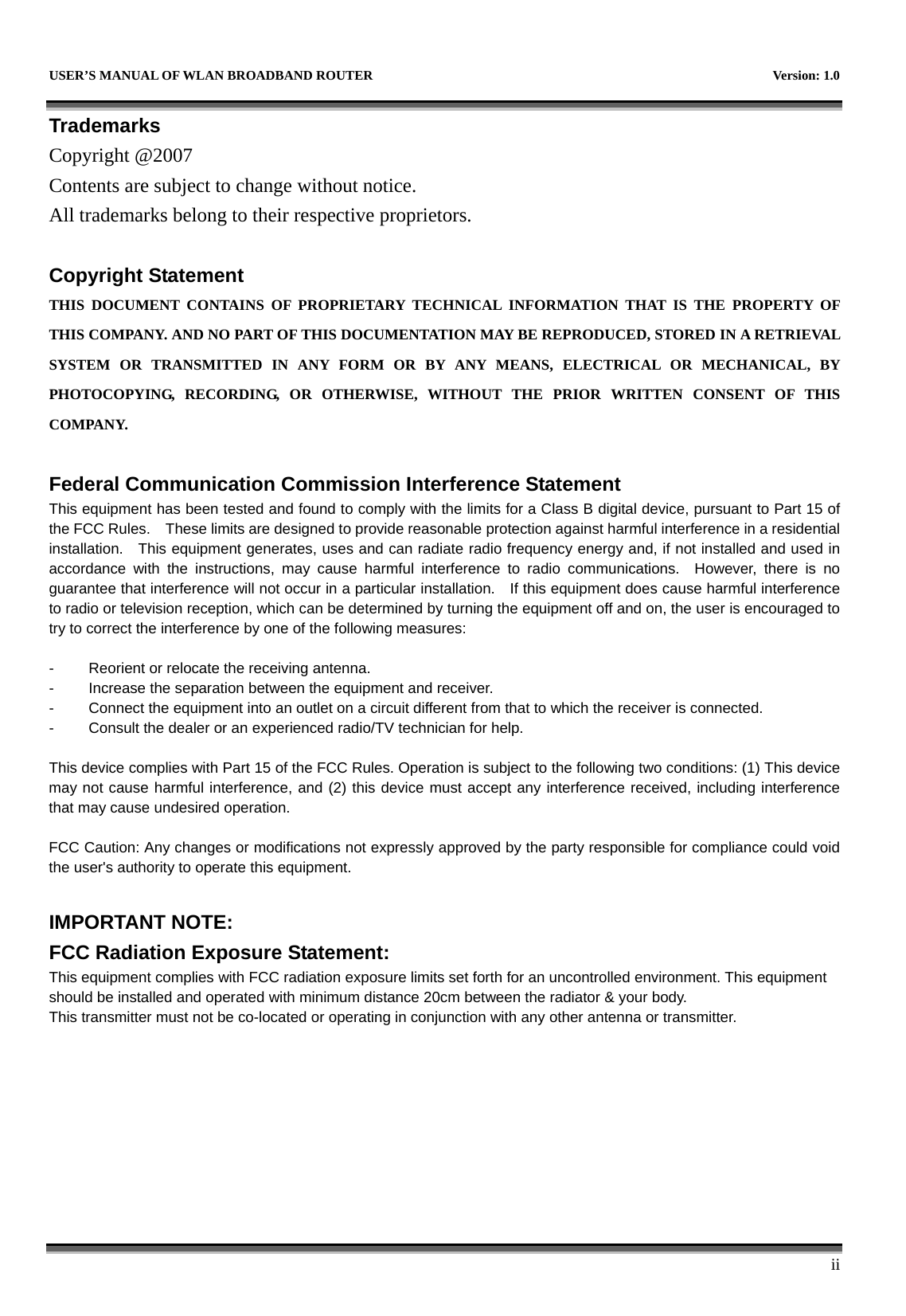
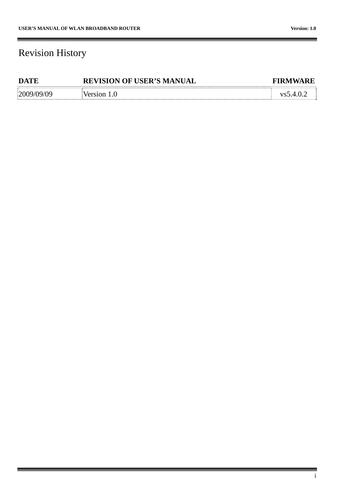
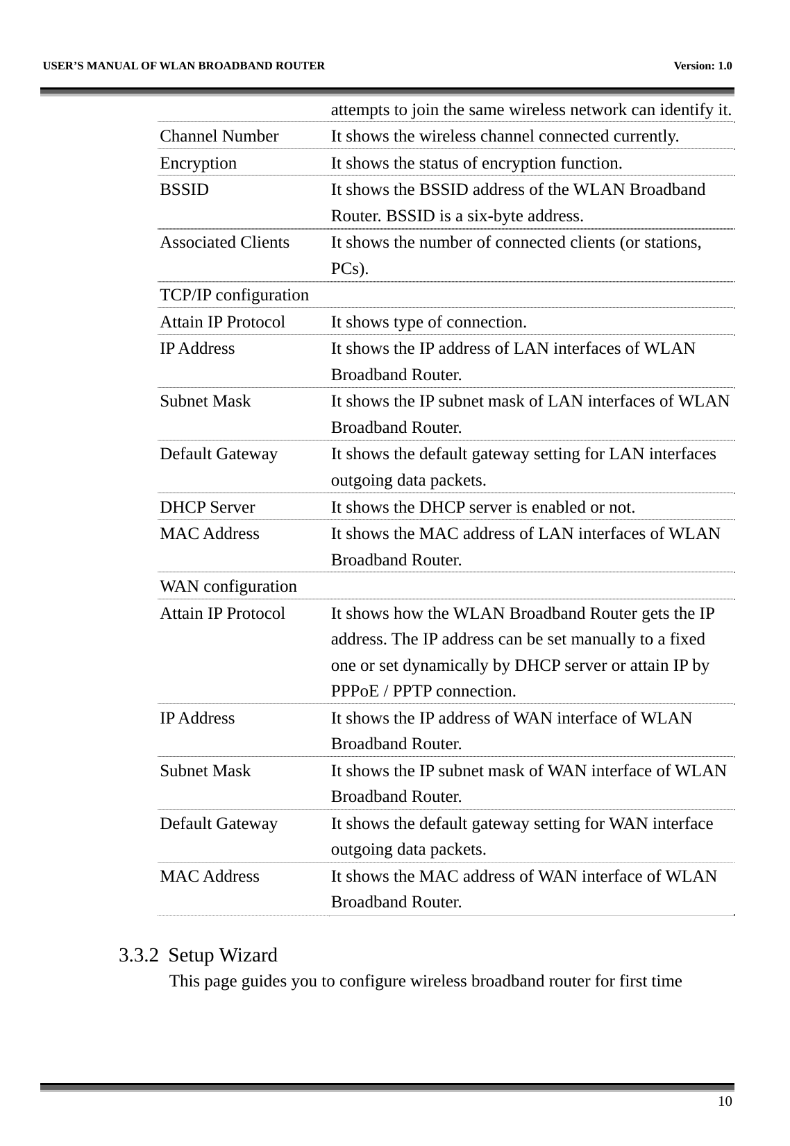
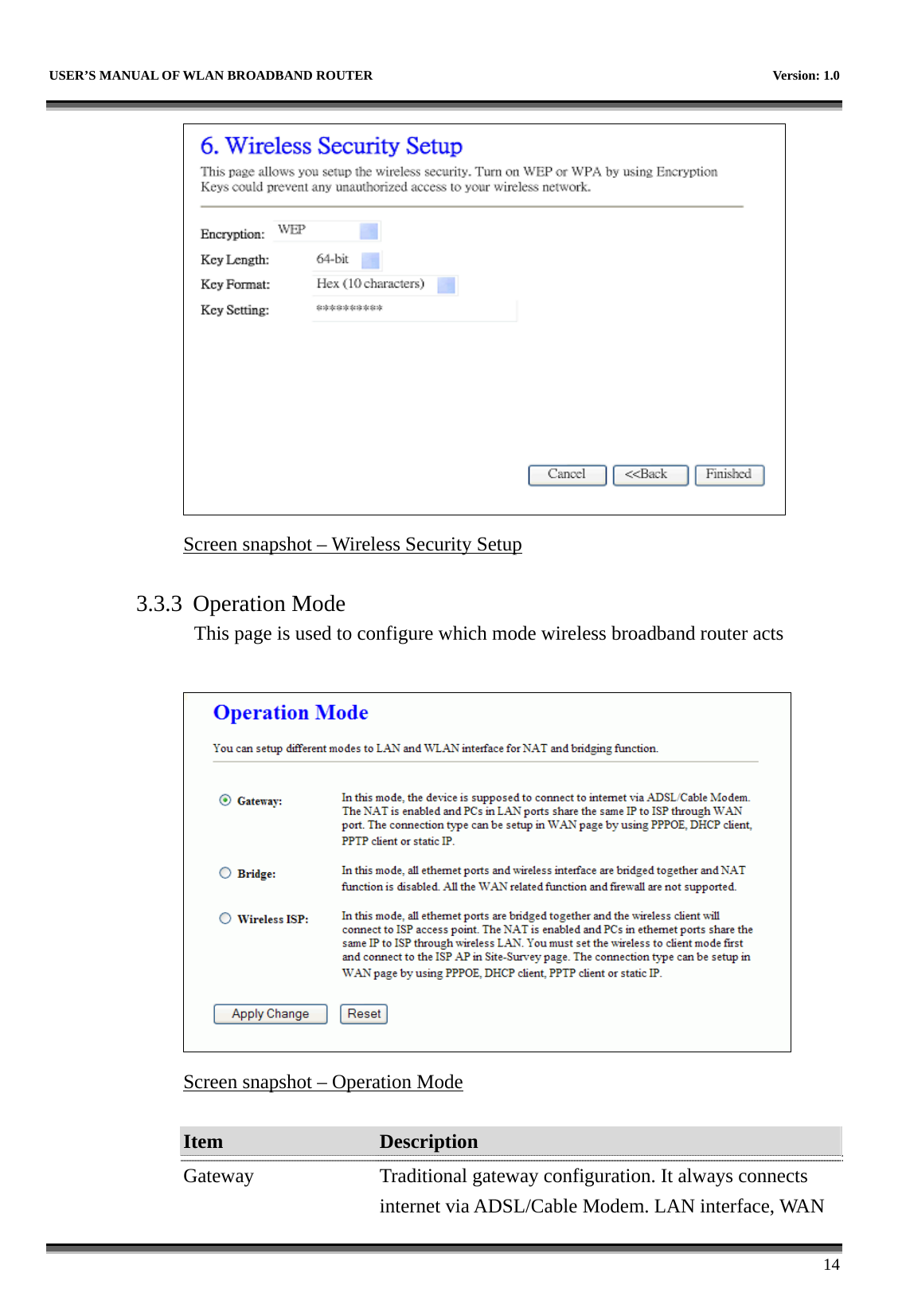
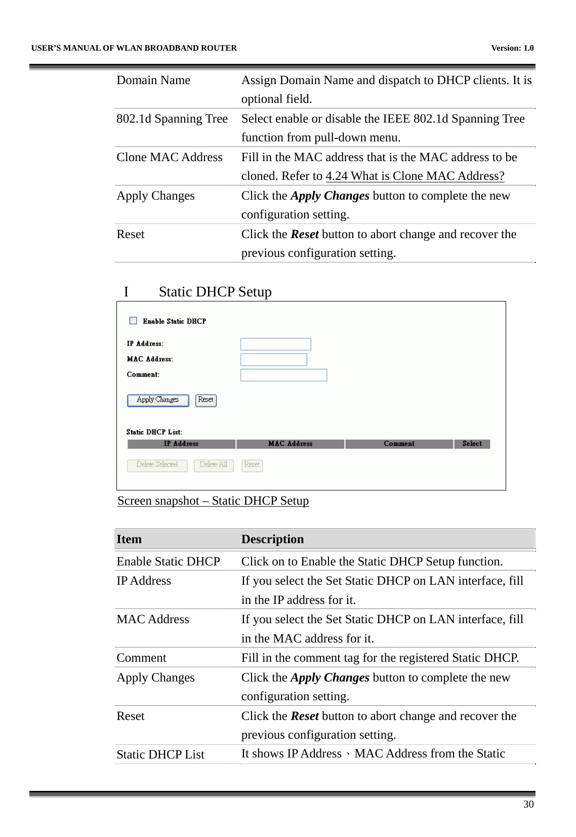
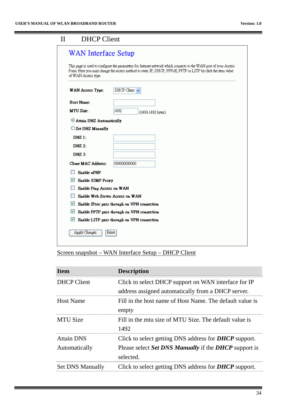
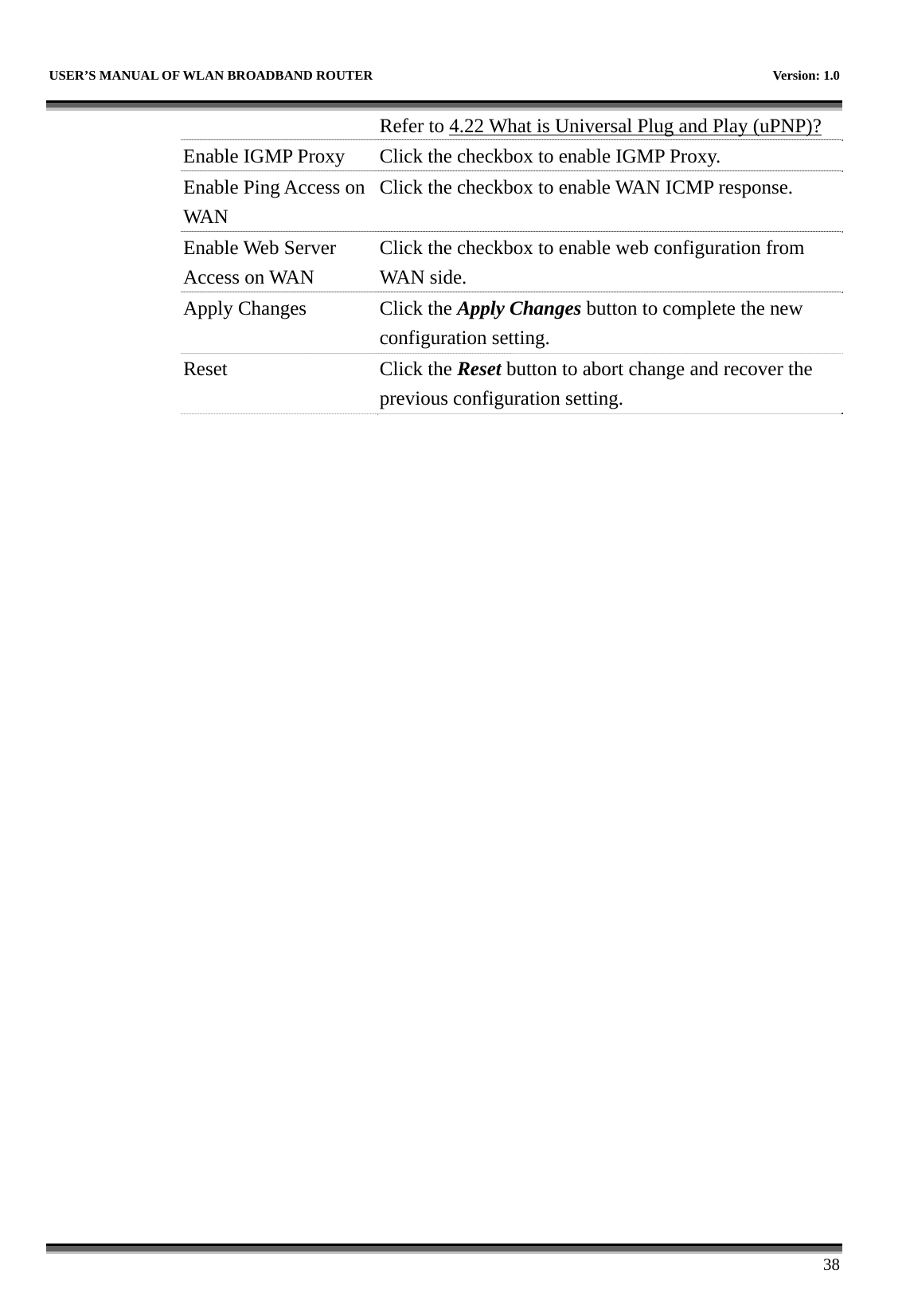
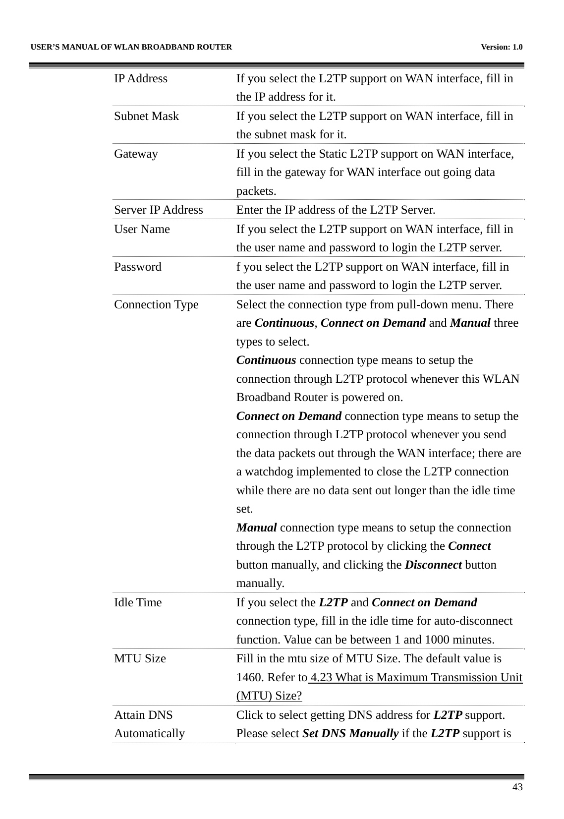
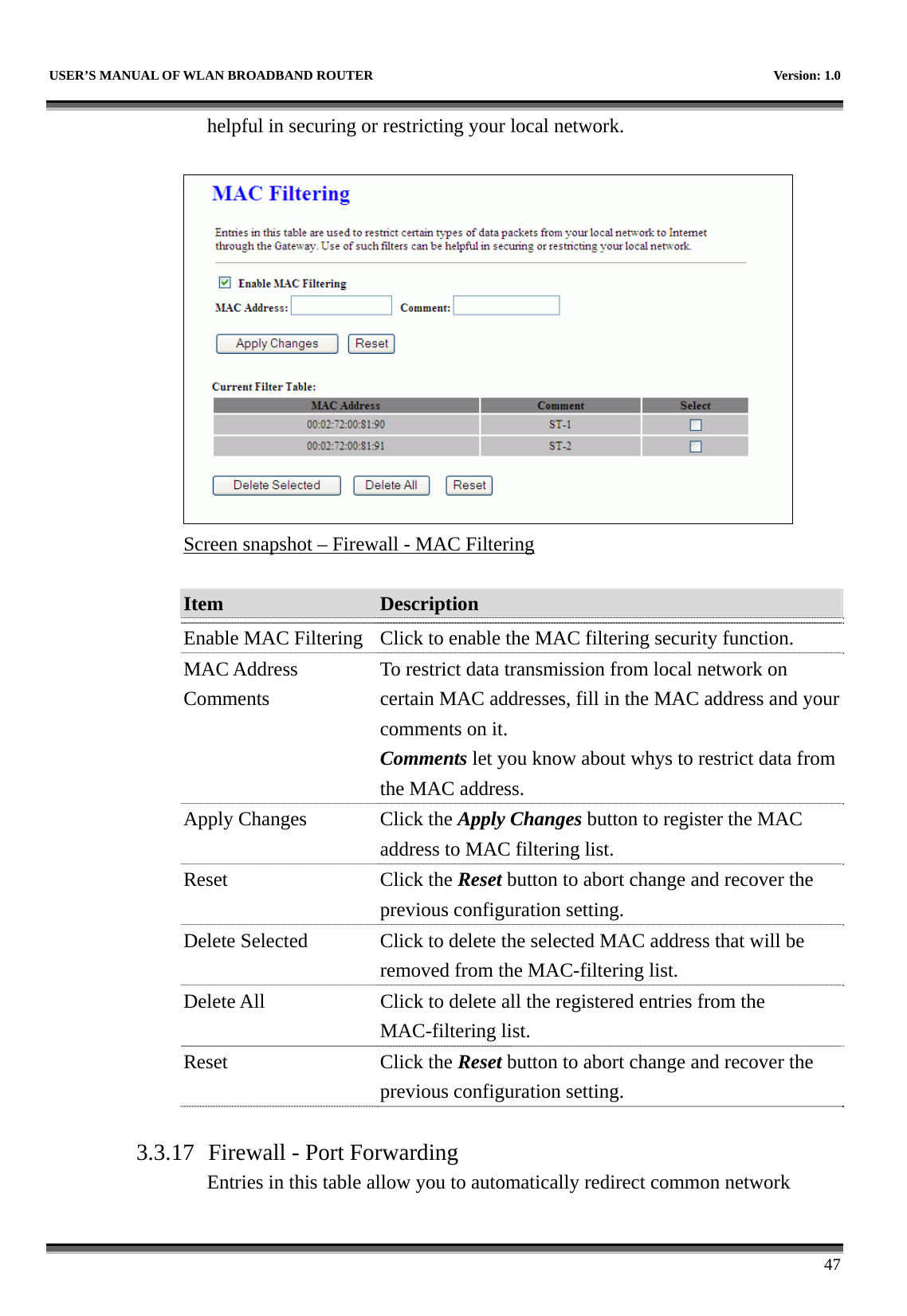
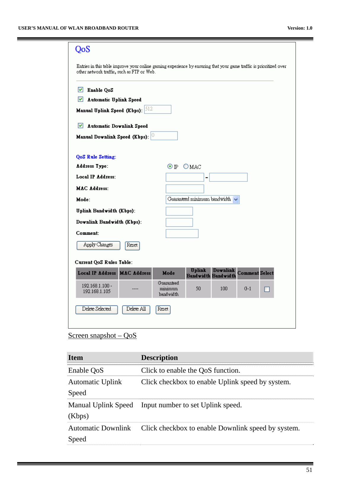
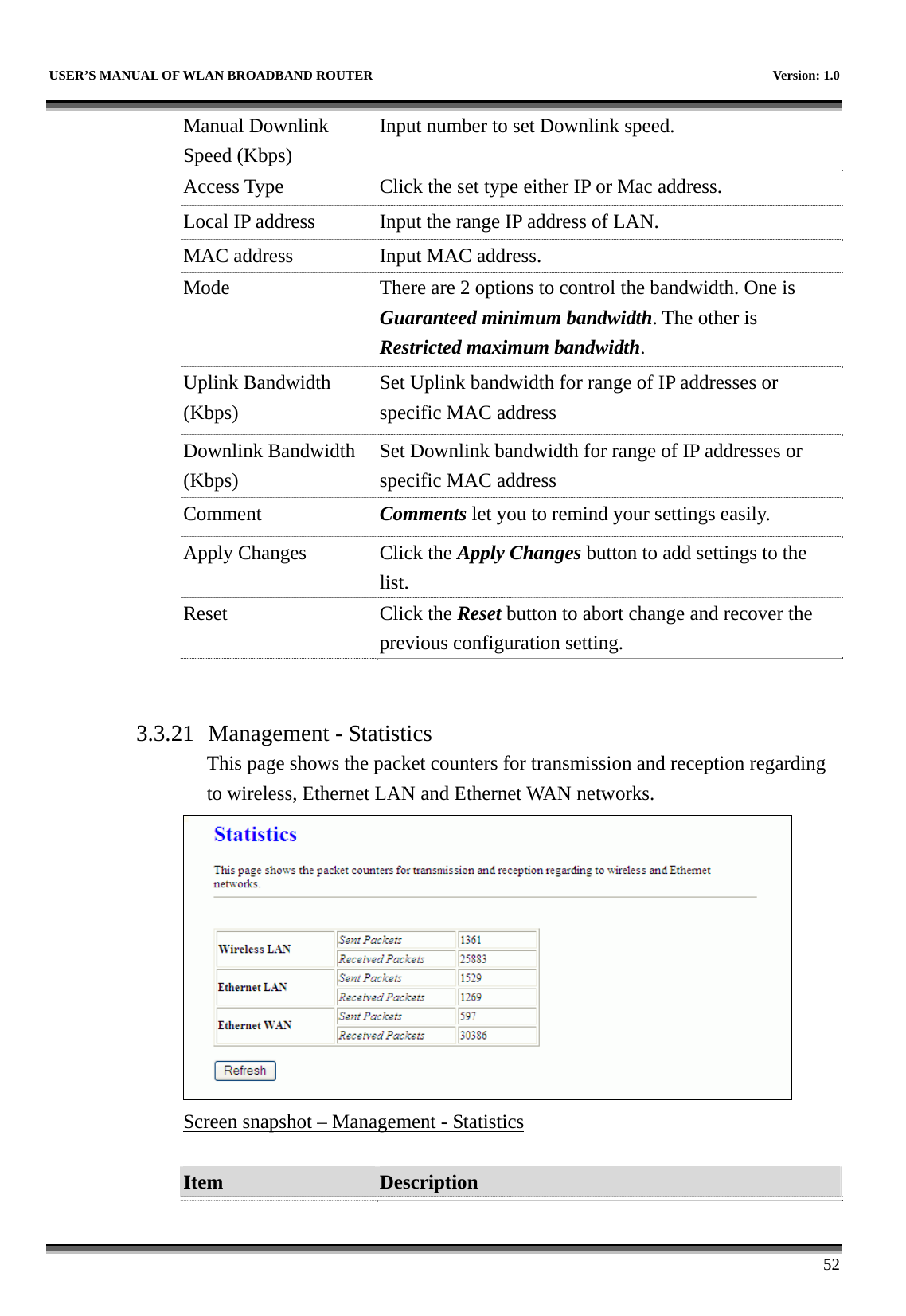
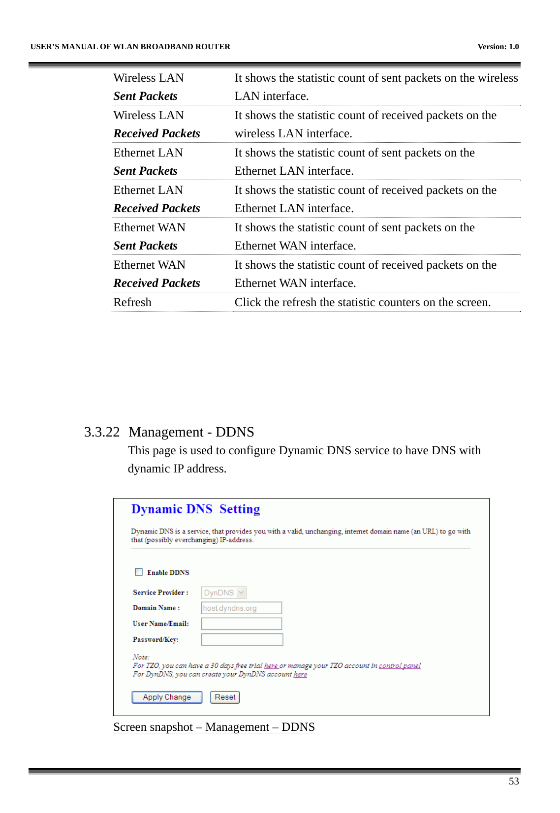
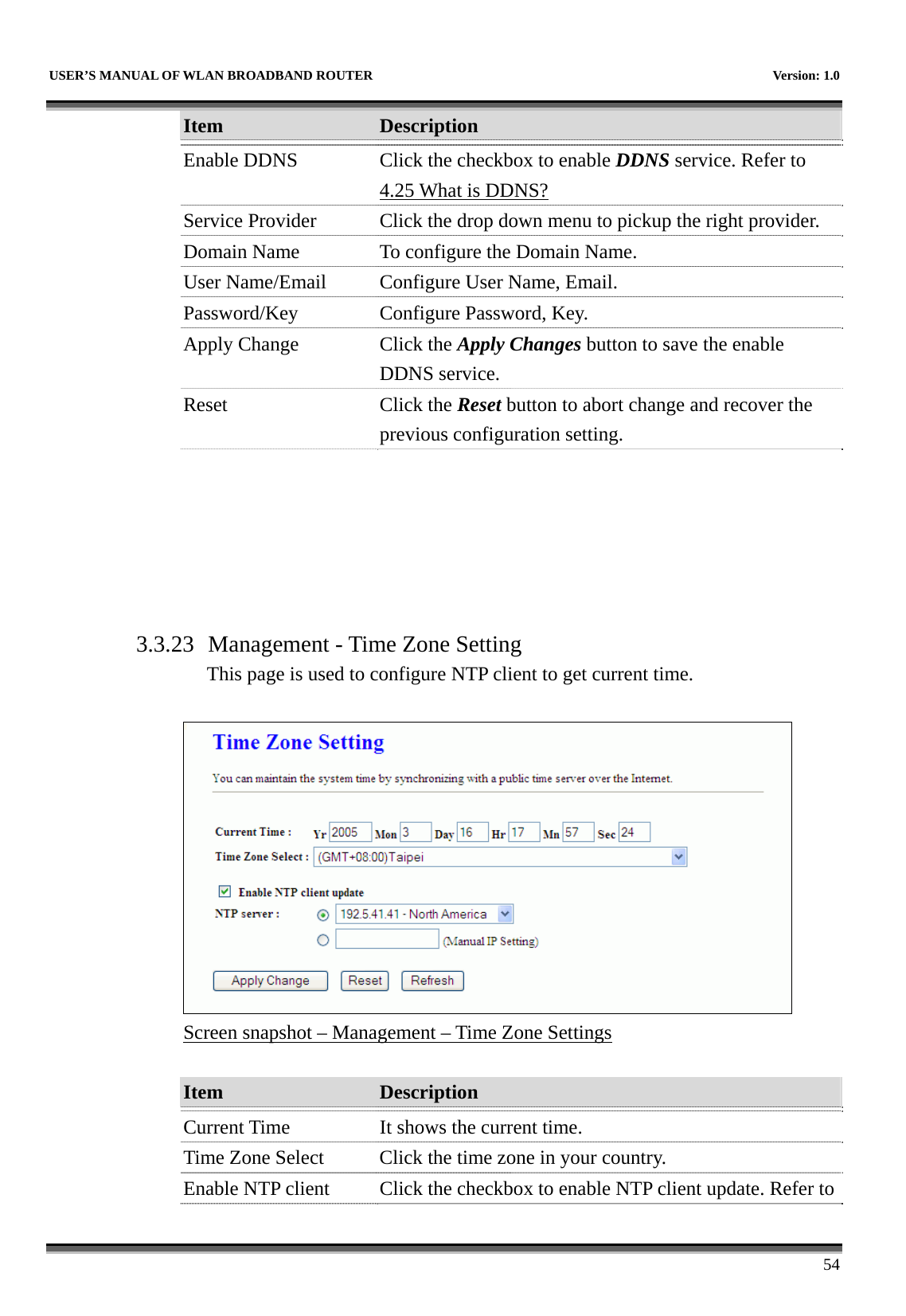
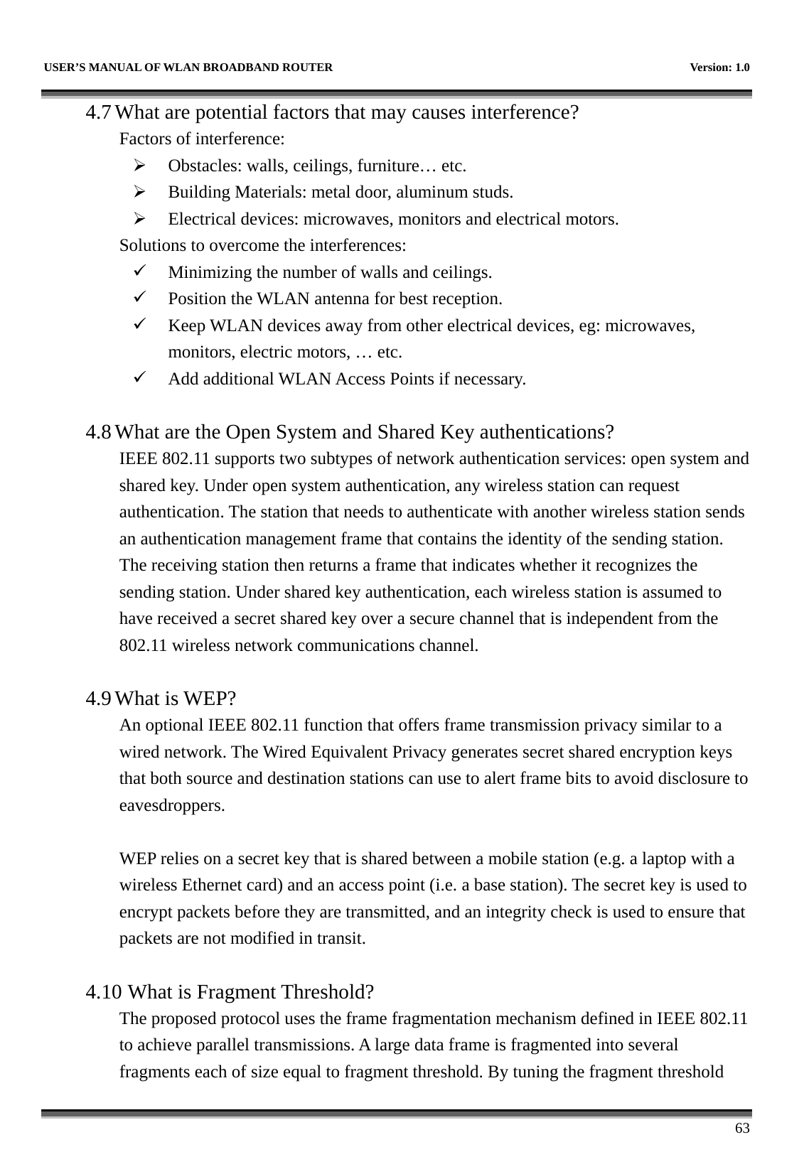
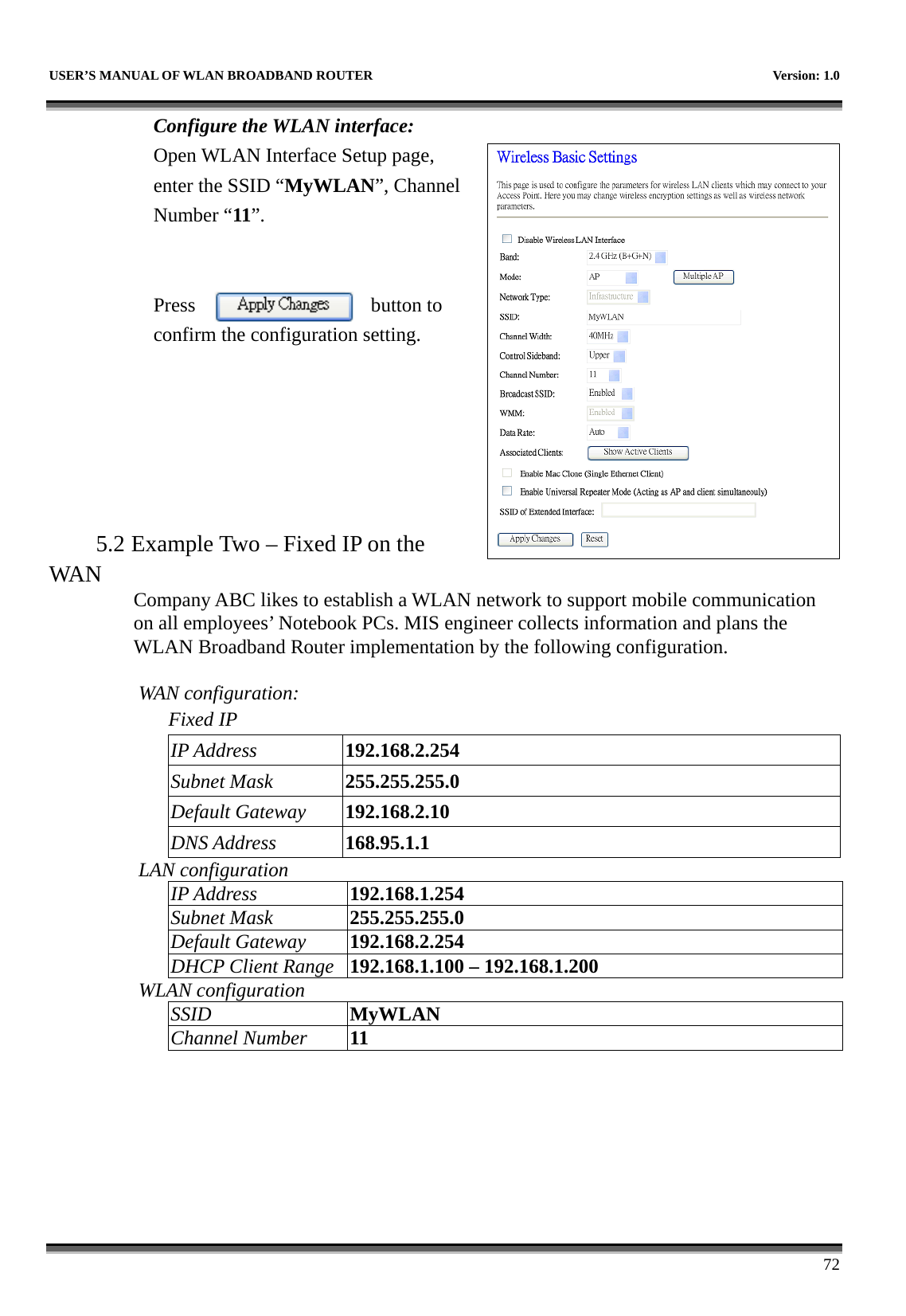
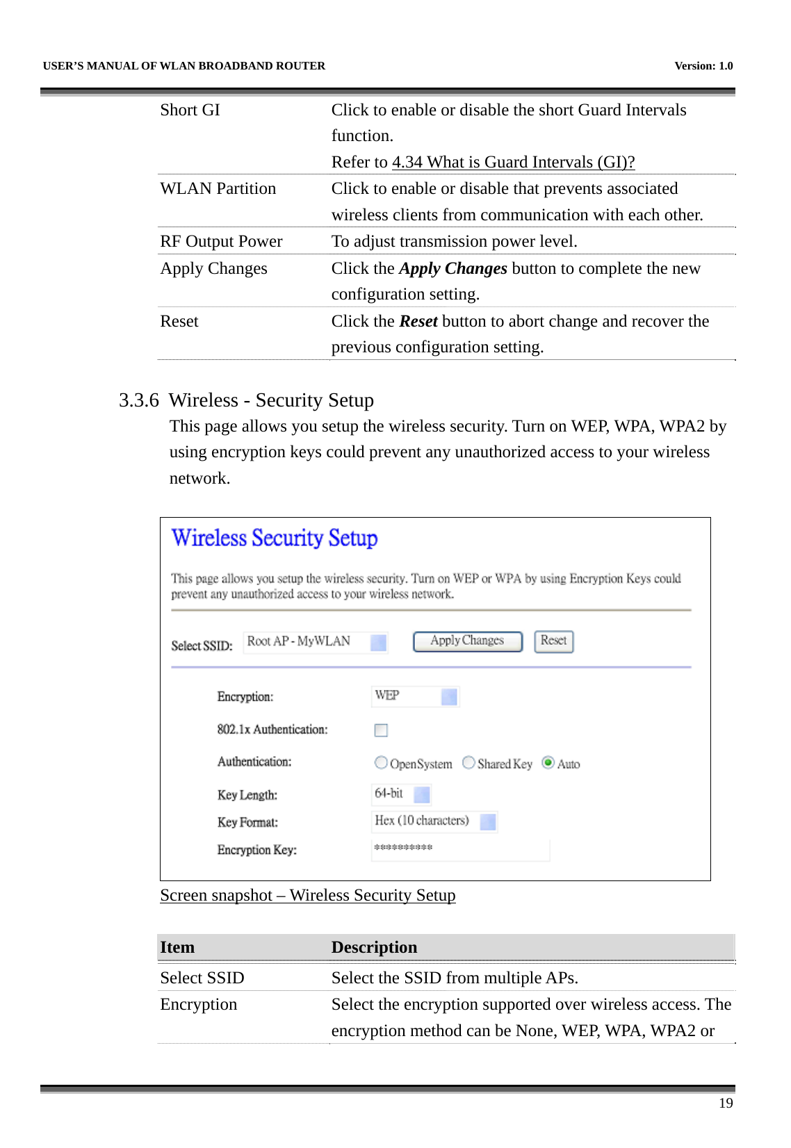
![USER’S MANUAL OF WLAN BROADBAND ROUTER Version: 1.0 17 bytes long. Channel Width Select the operating channel width 20 MHz or 40 MHz. [N band only] Control Sideband Select the Sideband with Upper or Lower for channel width 40MHz. [N band only] Channel Number Select the wireless communication channel from pull-down menu. Broadcast SSID Click to enable or disable the SSID broadcast function. Refer to 4.14 What is SSID Broadcast? WMM Click Enabled/Disabled to init WMM feature. Data Rate Select the transmission data rate from pull-down menu. Data rate can be auto-select, 1M to 54Mbps or MCS. Refer to 4.32 What is Modulation Coding Schemes (MCS)? Associated Clients Click the Show Active Clients button to open Active Wireless Client Table that shows the MAC address, transmit-packet, receive-packet and transmission-rate for each associated wireless client. Enable Mac Clone (Single Ethernet Client)Take Laptop NIC MAC address as wireless client MAC address. [Client Mode only] Enable Universal Repeater Mode Click to enable Universal Repeater Mode SSID of Extended Interface Assign SSID when enables Universal Repeater Mode. Apply Changes Click the Apply Changes button to complete the new configuration setting. Reset Click the Reset button to abort change and recover the previous configuration setting. 3.3.5 Wireless - Advanced Settings These settings are only for more technically advanced users who have a sufficient knowledge about wireless LAN. These settings should not be changed unless you know what effect the changes will have on your WLAN Broadband Router.](https://usermanual.wiki/CC-and-C-Technologies/WA6212/User-Guide-1660396-Page-25.png)
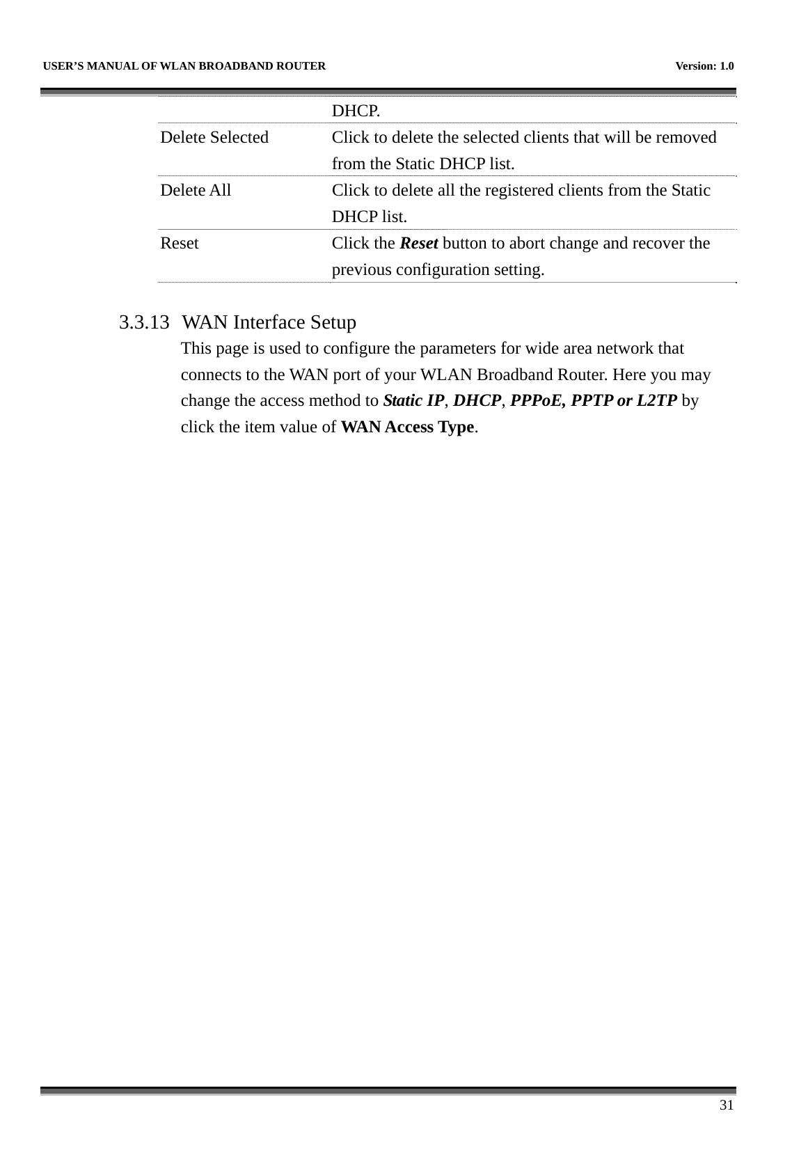
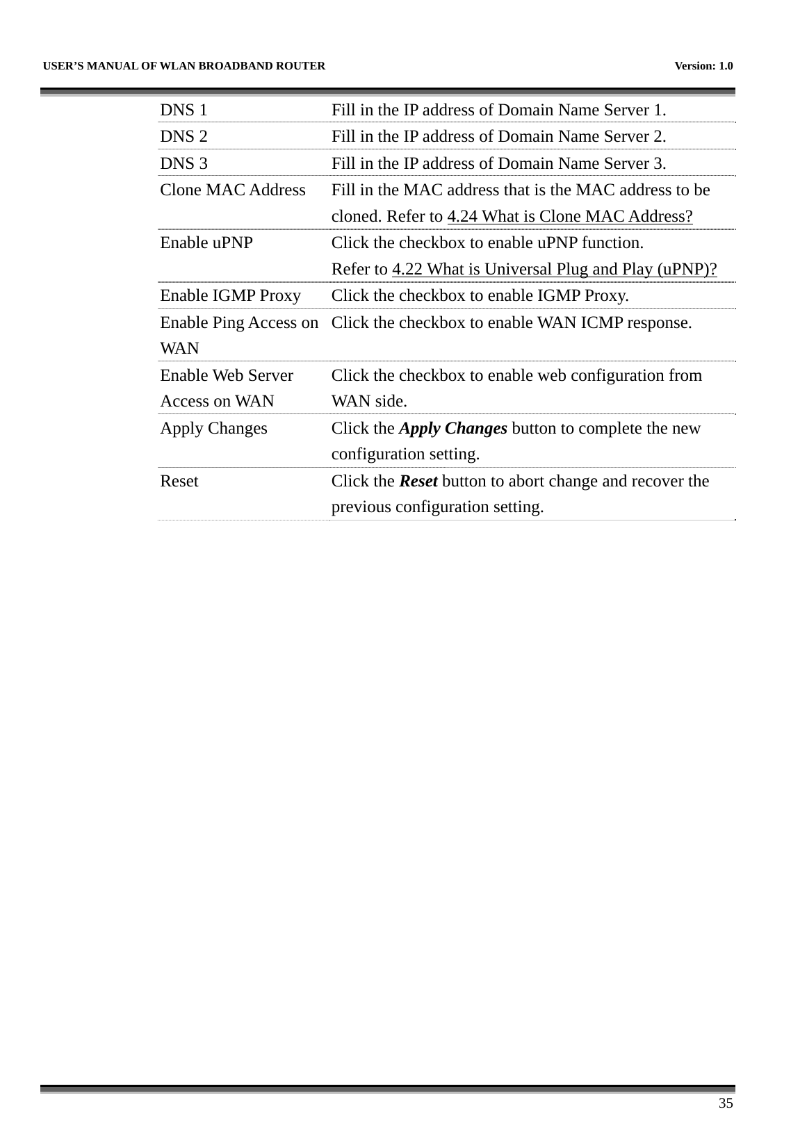
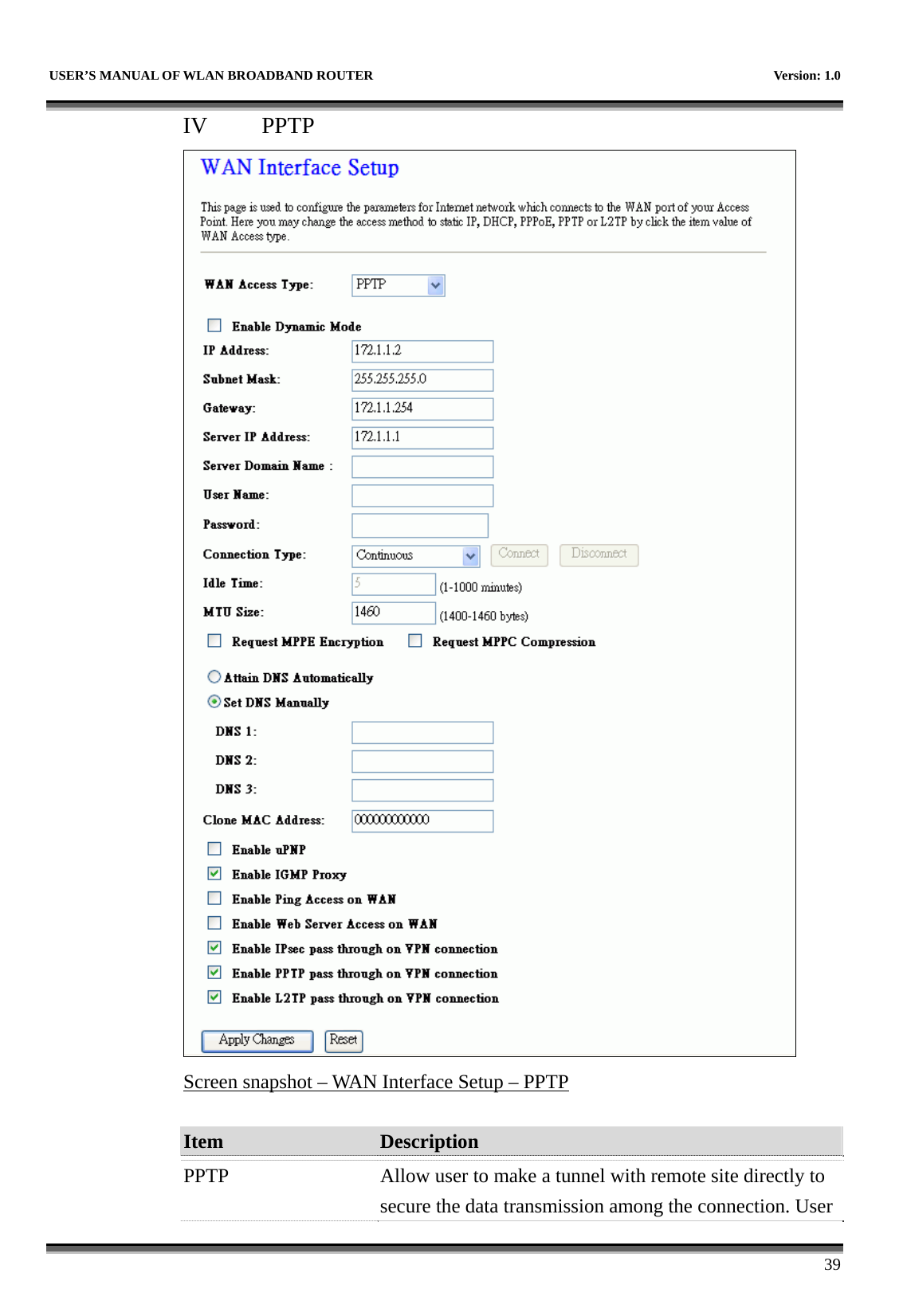
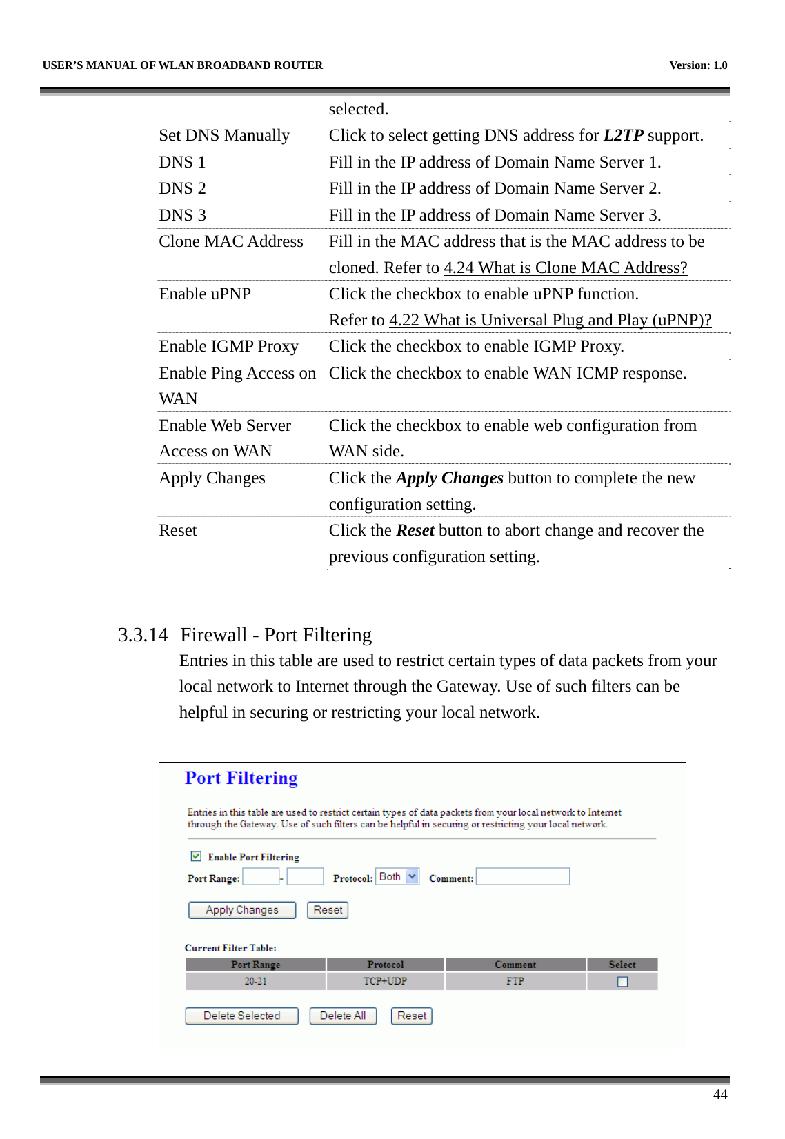
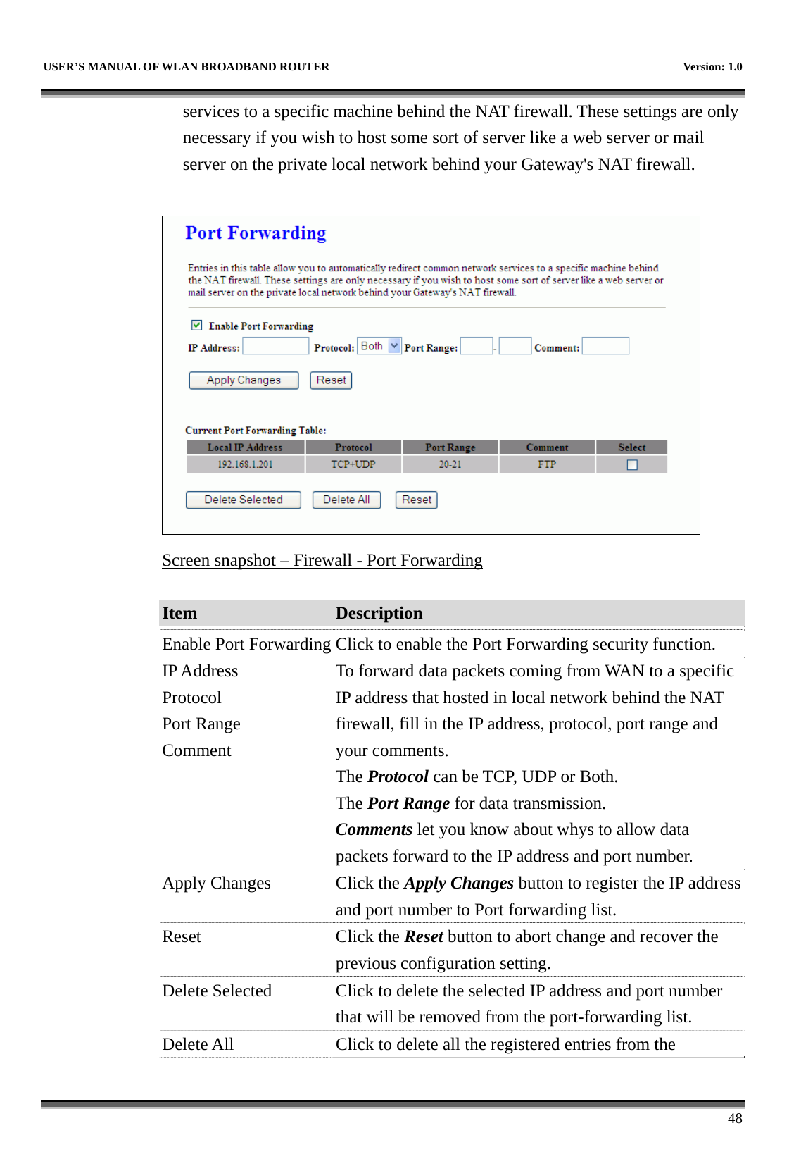
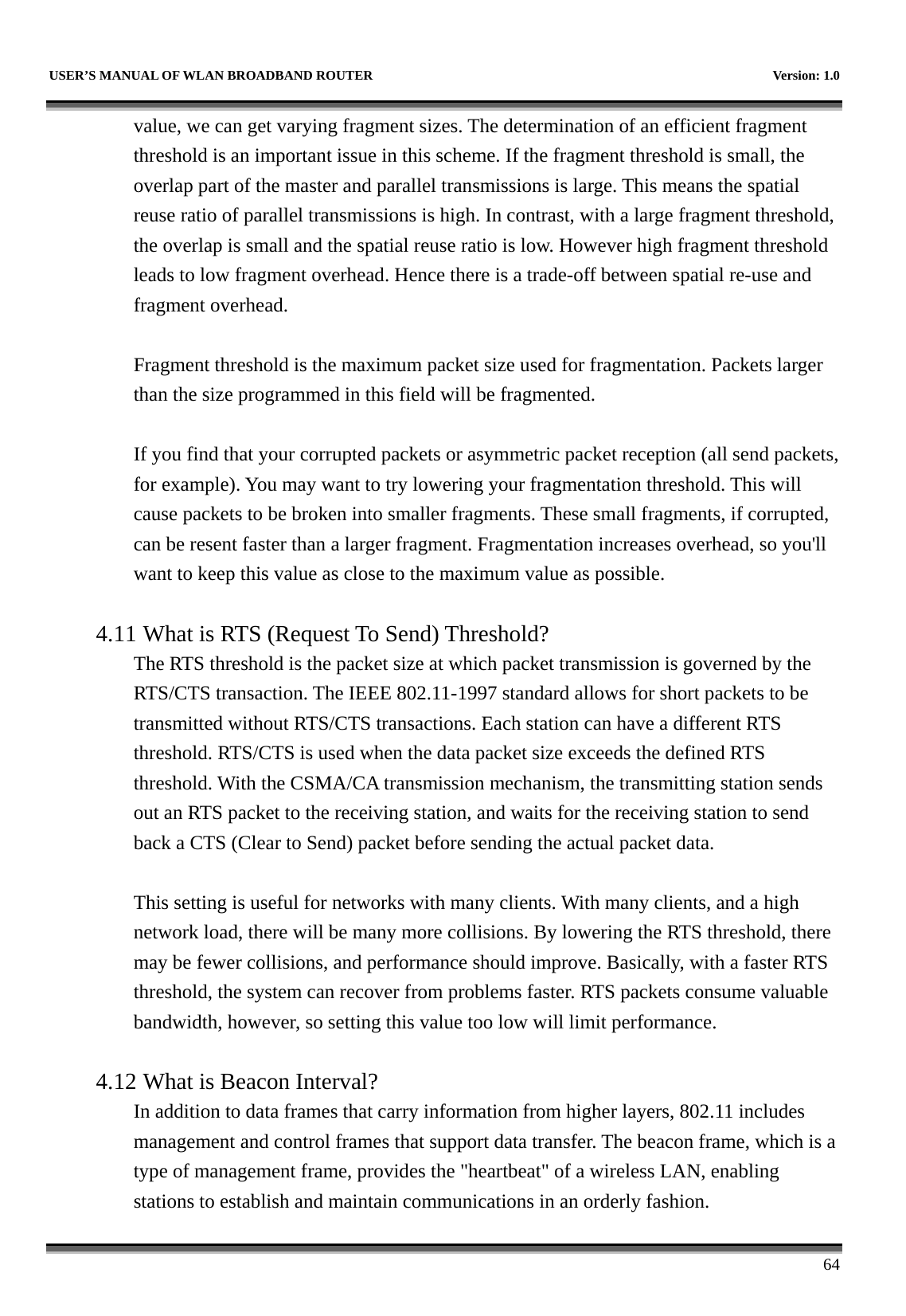
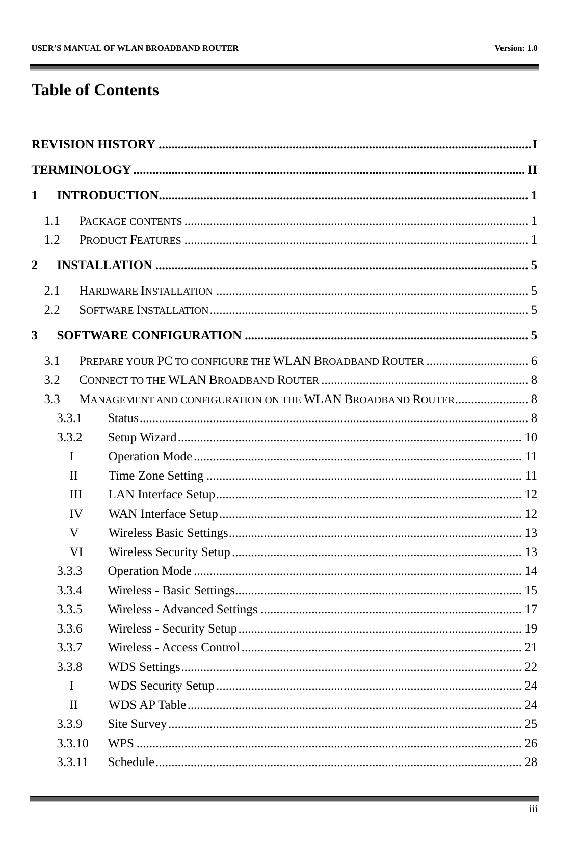
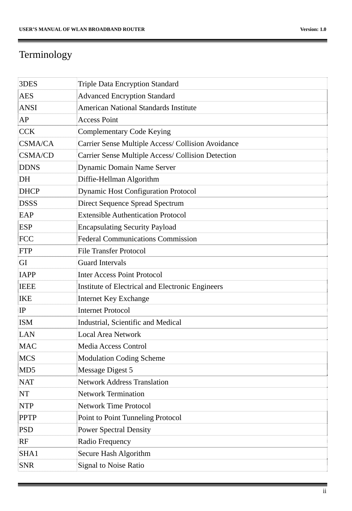
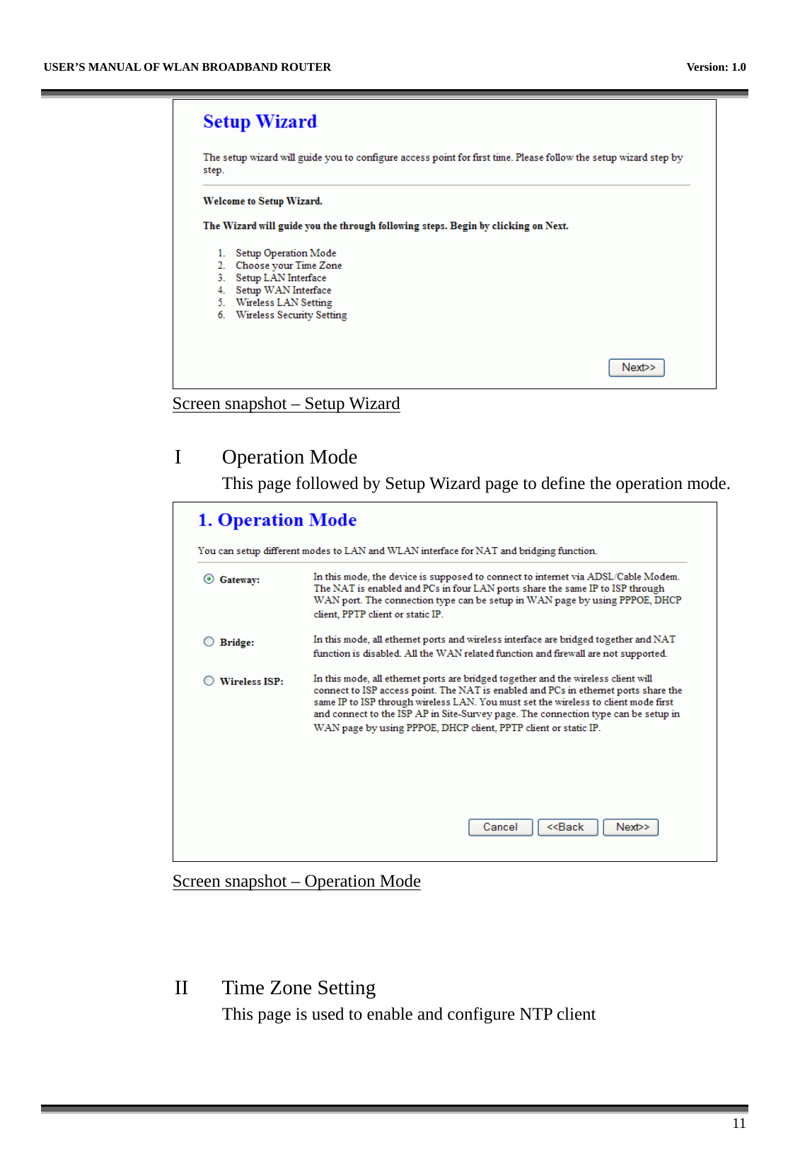
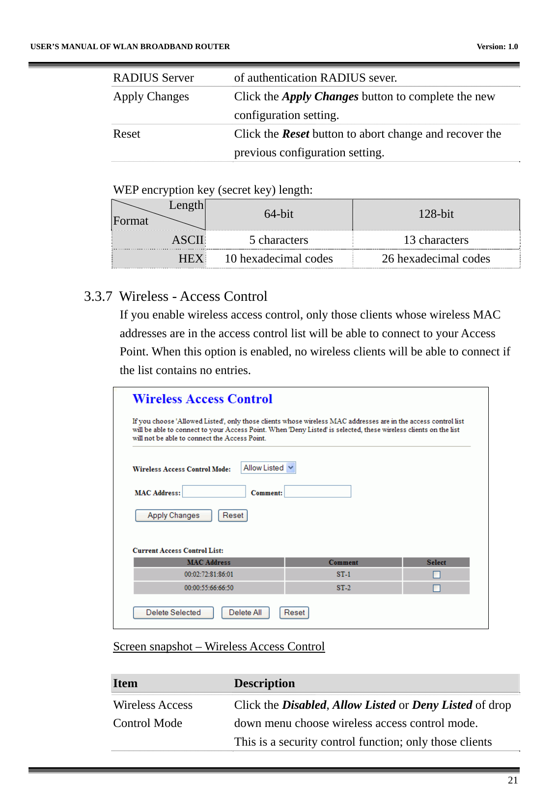
![USER’S MANUAL OF WLAN BROADBAND ROUTER Version: 1.0 20 WPA-Mixed Refer to 4.9 What is WEP? 4.15 What is Wi-Fi Protected Access (WPA)? 4.16 What is WPA2? Use 802.1x Authentication While Encryption is selected to be WEP. Click the check box to enable IEEE 802.1x authentication function. Refer to 4.17 What is 802.1x Authentication? Authentication Type Click to select the authentication type in Open System, Shared Key or Auto selection. Key Length Select the WEP shared secret key length from pull-down menu. The length can be chose between 64-bit and 128-bit (known as “WEP2”) keys. The WEP key is composed of initialization vector (24 bits) and secret key (40-bit or 104-bit). Key Format Select the WEP shared secret key format from pull-down menu. The format can be chose between plant text (ASCII) and hexadecimal (HEX) code. Encryption Key Secret key of WEP security encryption function. WPA Authentication Mode While Encryption is selected to be WPA. Click to select the WPA Authentication Mode with Enterprise (RADIUS) or Personal (Pre-Shared Key). Refer to 4.15 What is Wi-Fi Protected Access (WPA)? WPA Cipher Suite Select the Cipher Suite for WPA encryption. 4.18 What is Temporal Key Integrity Protocol (TKIP)? 4.19 What is Advanced Encryption Standard (AES)? WPA2 Cipher Suite Select the Cipher Suite for WPA2 encryption. Pre-Shared Key Format While Encryption is selected to be WPA. Select the Pre-shared key format from the pull-down menu. The format can be Passphrase or Hex (64 characters). [WPA, Personal(Pre-Shared Key) only] Pre-Shared Key Fill in the key value. [WPA, Personal(Pre-Shared Key) only] Enable Pre-Authentication Click to enable Pre-Authentication. [WPA2/WPA2 Mixed only, Enterprise only] Authentication Set the IP address, port and login password information](https://usermanual.wiki/CC-and-C-Technologies/WA6212/User-Guide-1660396-Page-28.png)
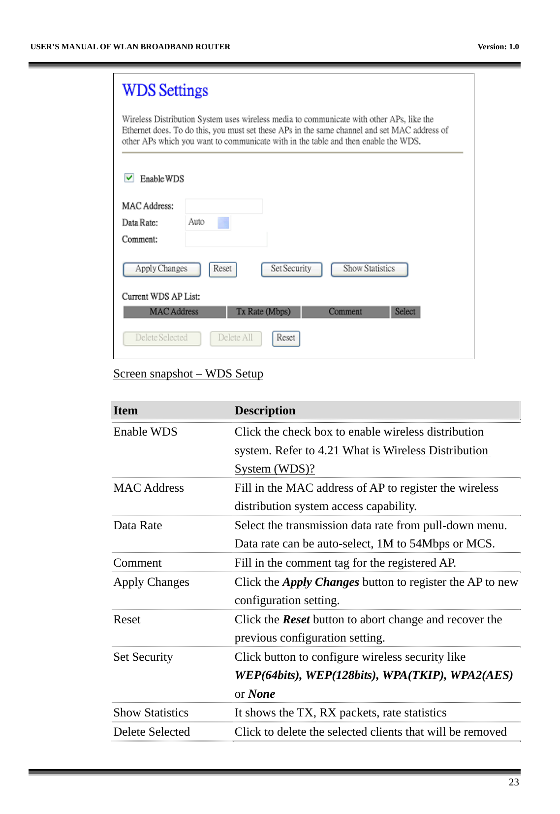
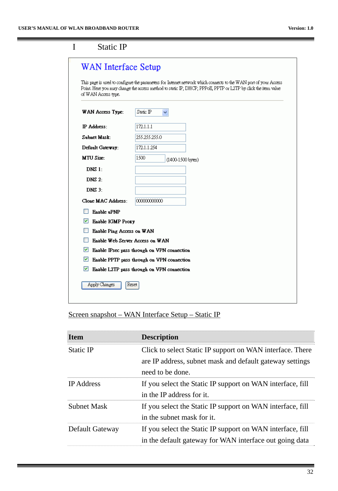
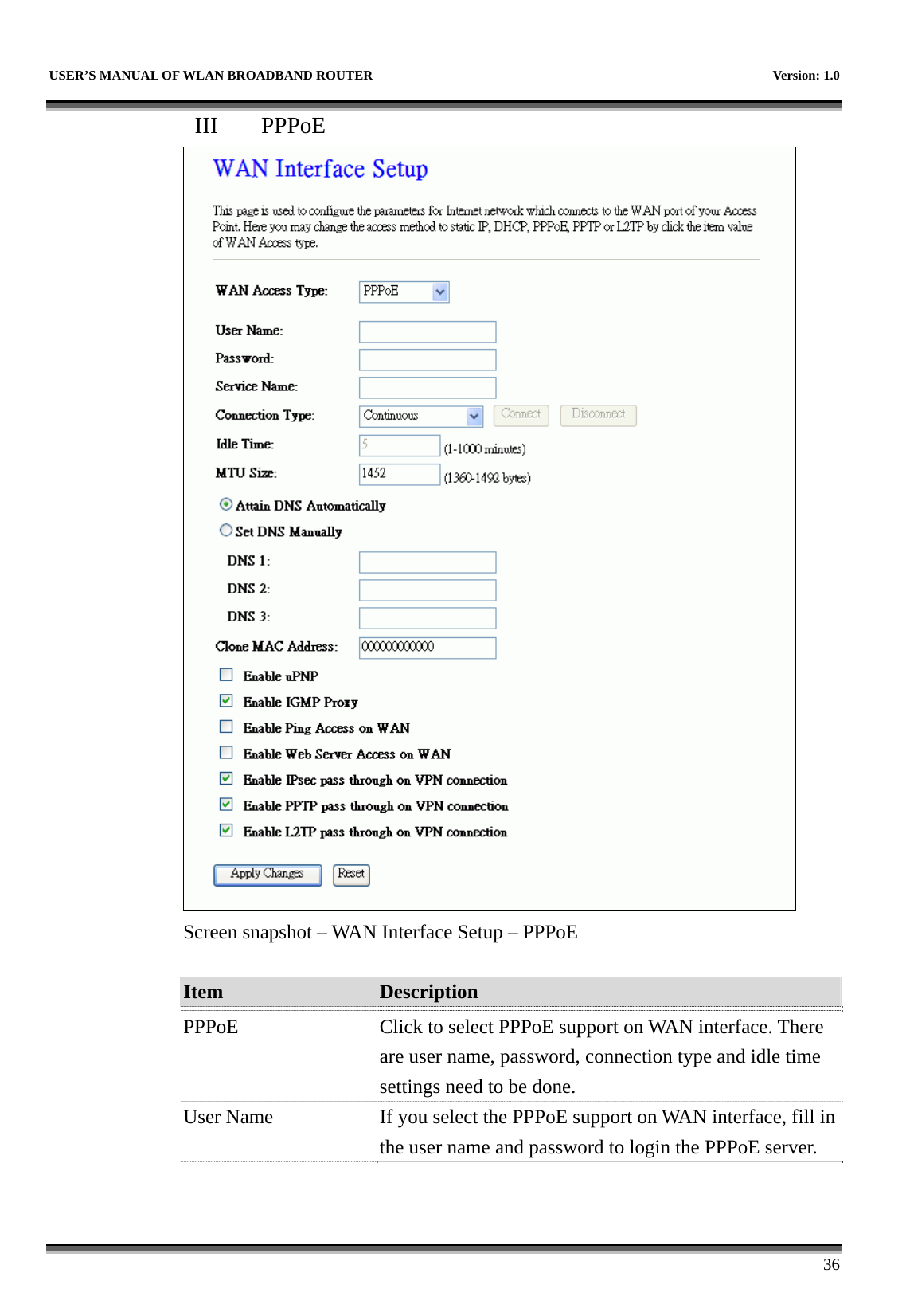
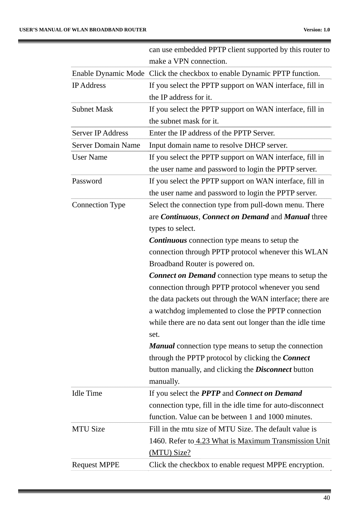
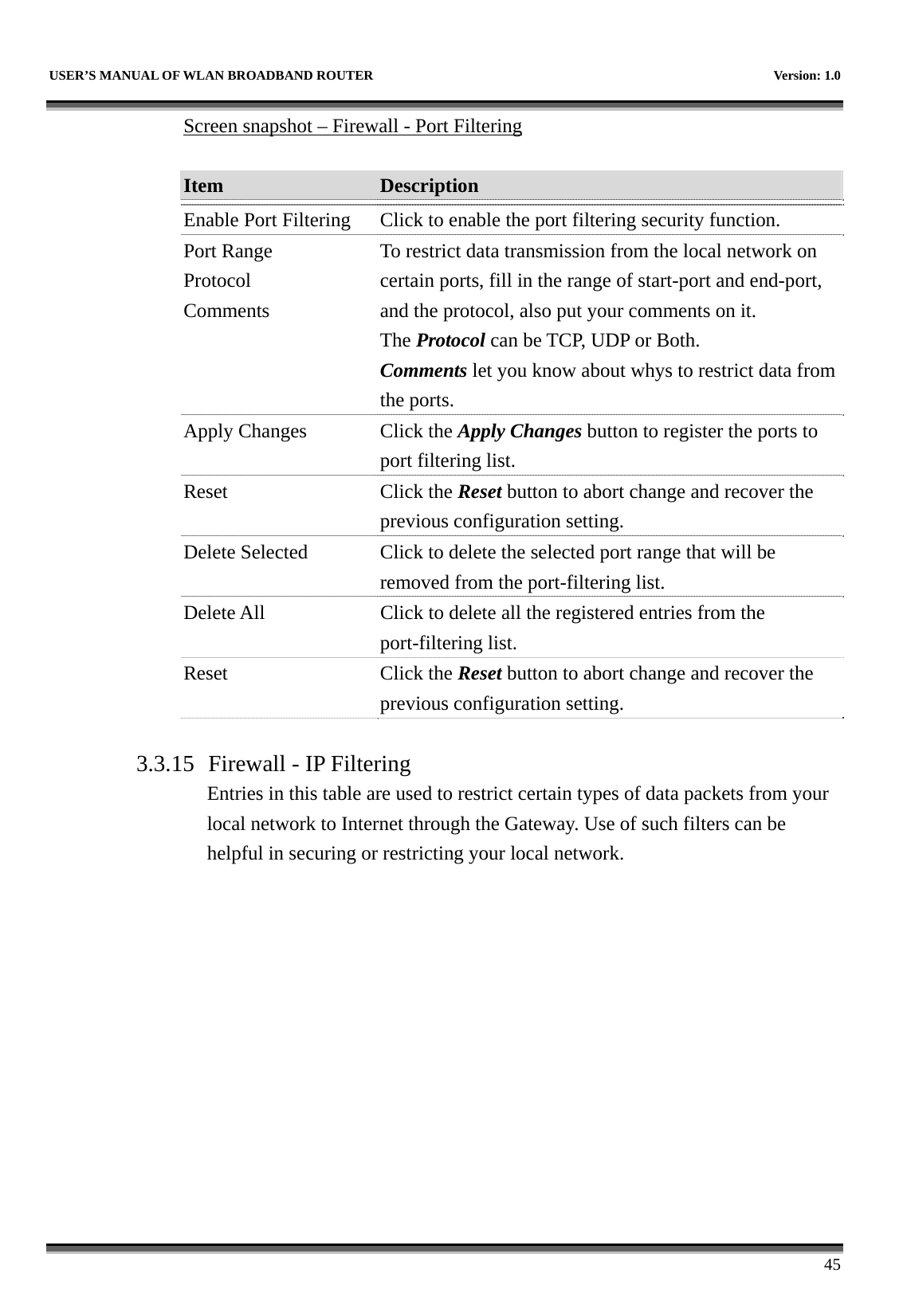
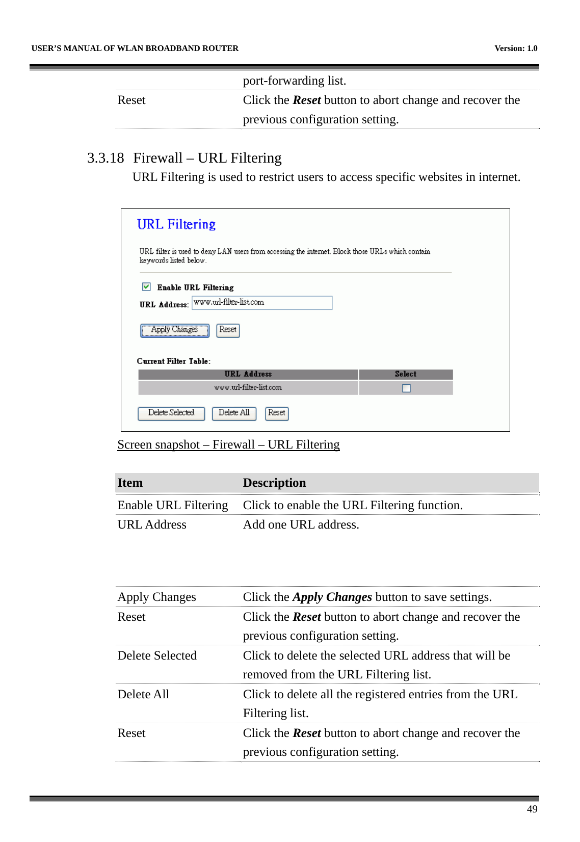
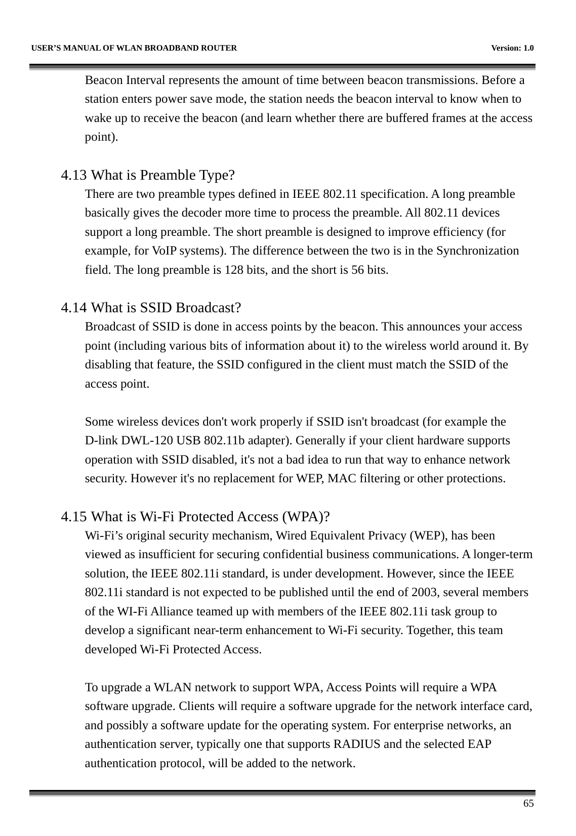
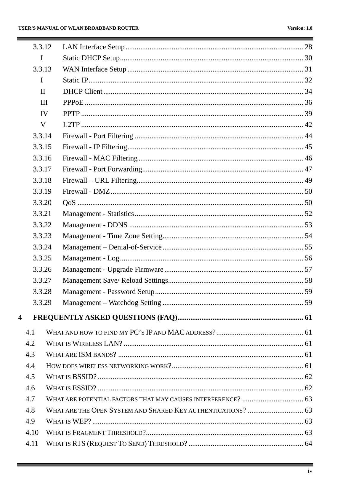
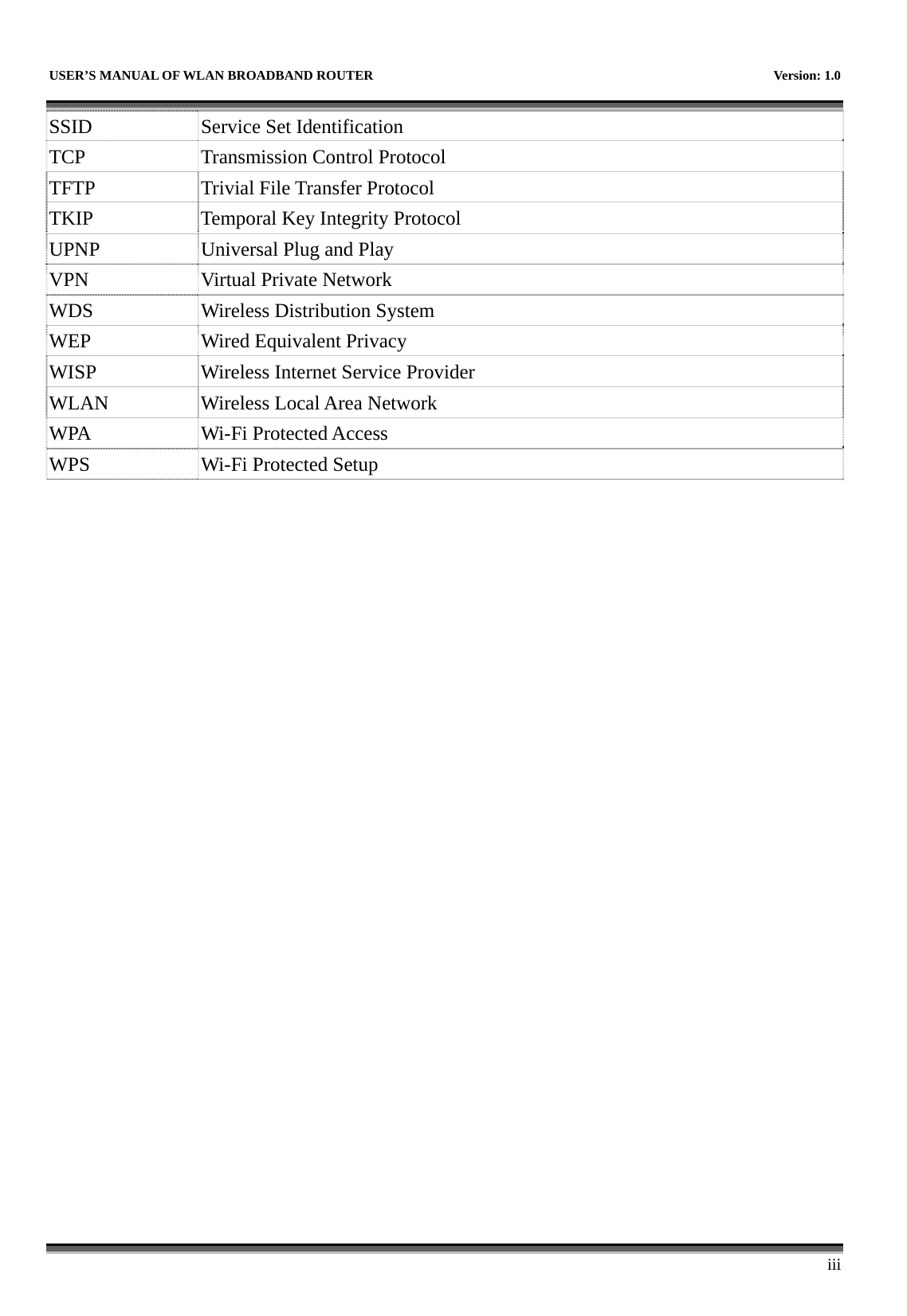
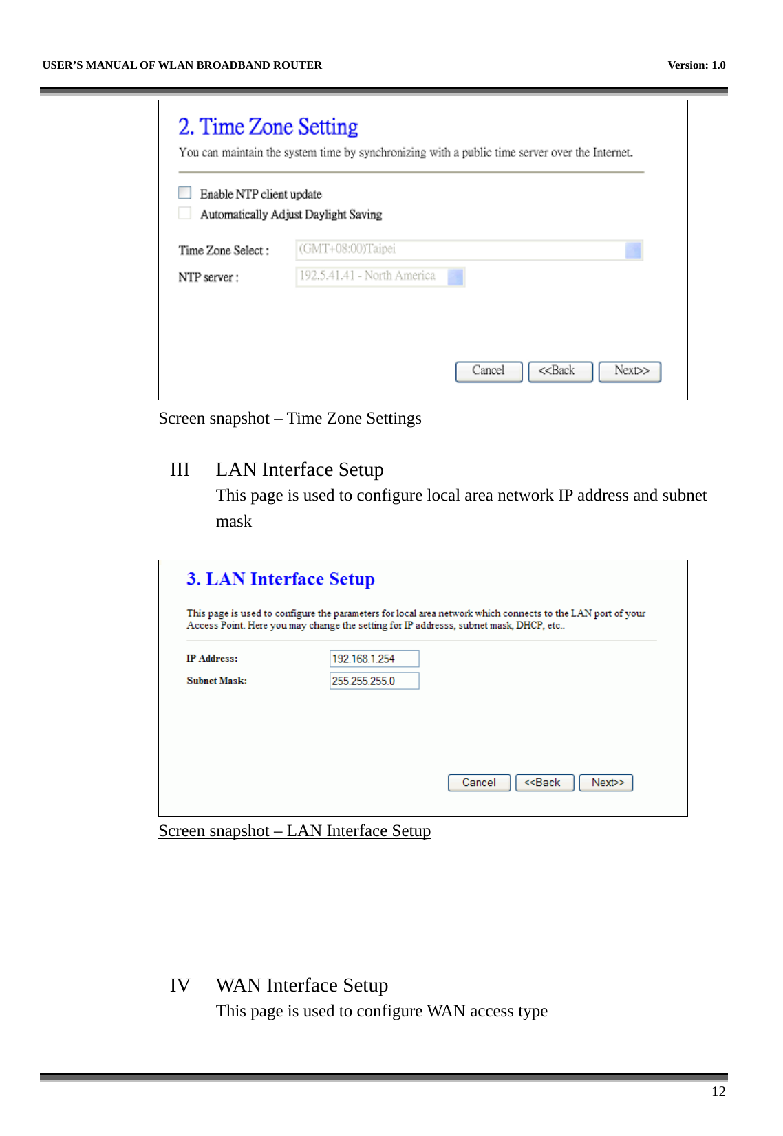
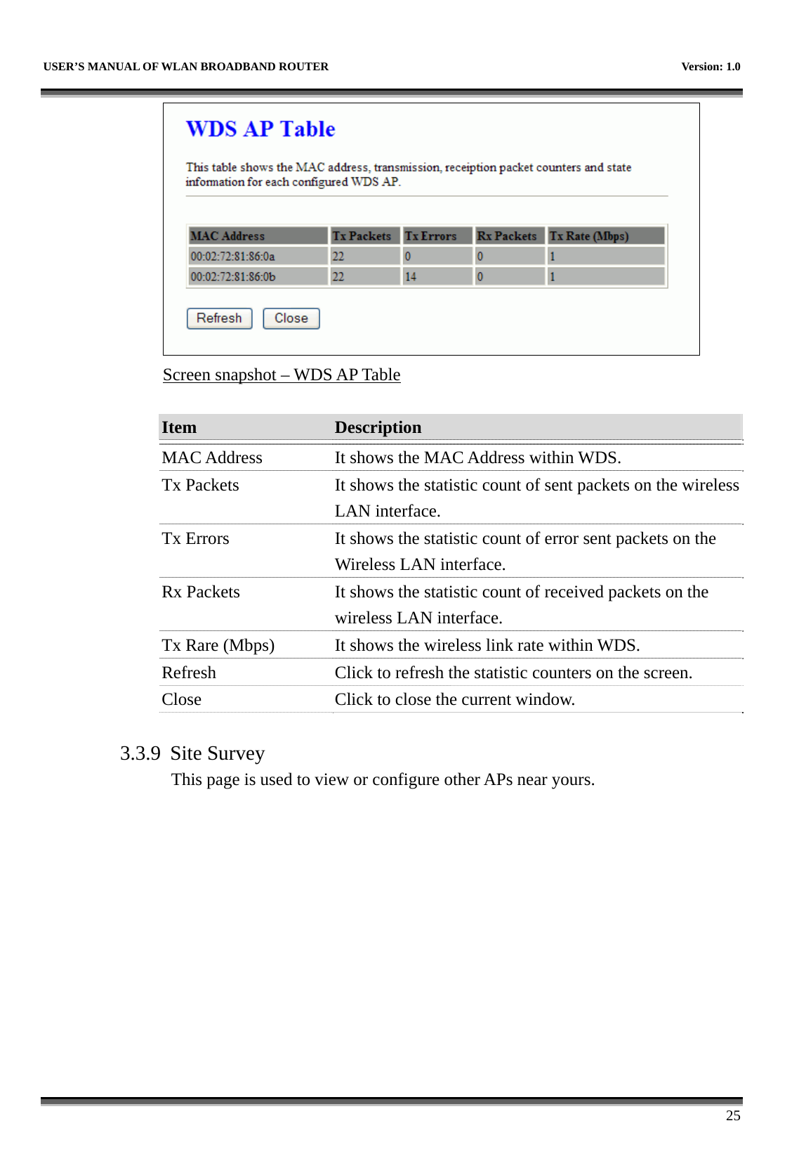
![USER’S MANUAL OF WLAN BROADBAND ROUTER Version: 1.0 24 from the wireless distribution system. Delete All Click to delete all the registered APs from the wireless distribution system allowed list. Reset Click the Reset button to abort change and recover the previous configuration setting. I WDS Security Setup Requirement: Set [Wireless]->[Basic Settings]->[Mode]->AP+WDS This page is used to configure the wireless security between APs. Refer to 3.3.6 Wireless Security Setup. Screen snapshot – WDS Security Setup II WDS AP Table This page is used to show WDS statistics](https://usermanual.wiki/CC-and-C-Technologies/WA6212/User-Guide-1660396-Page-32.png)
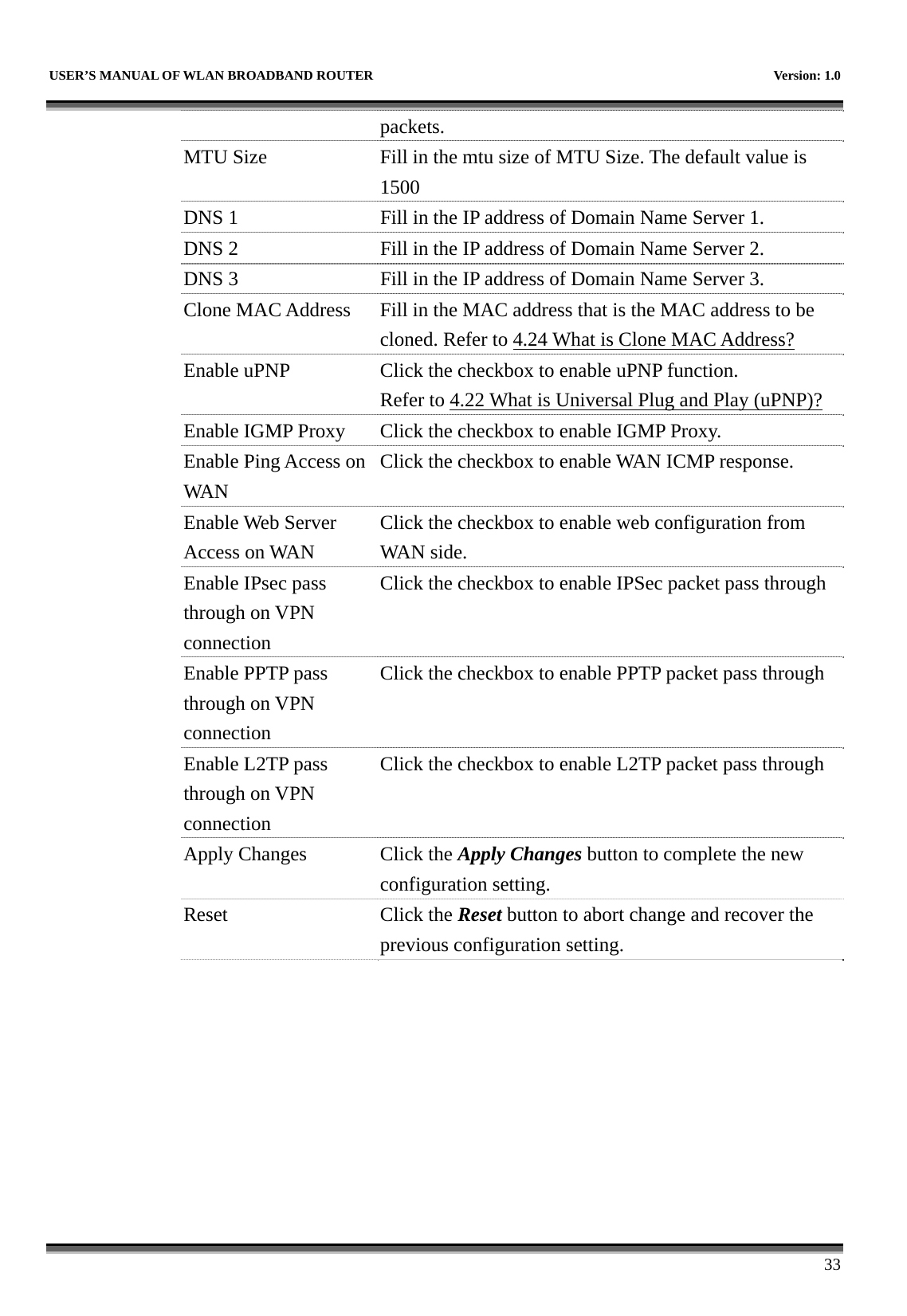
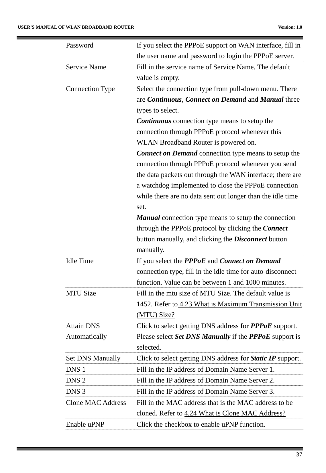
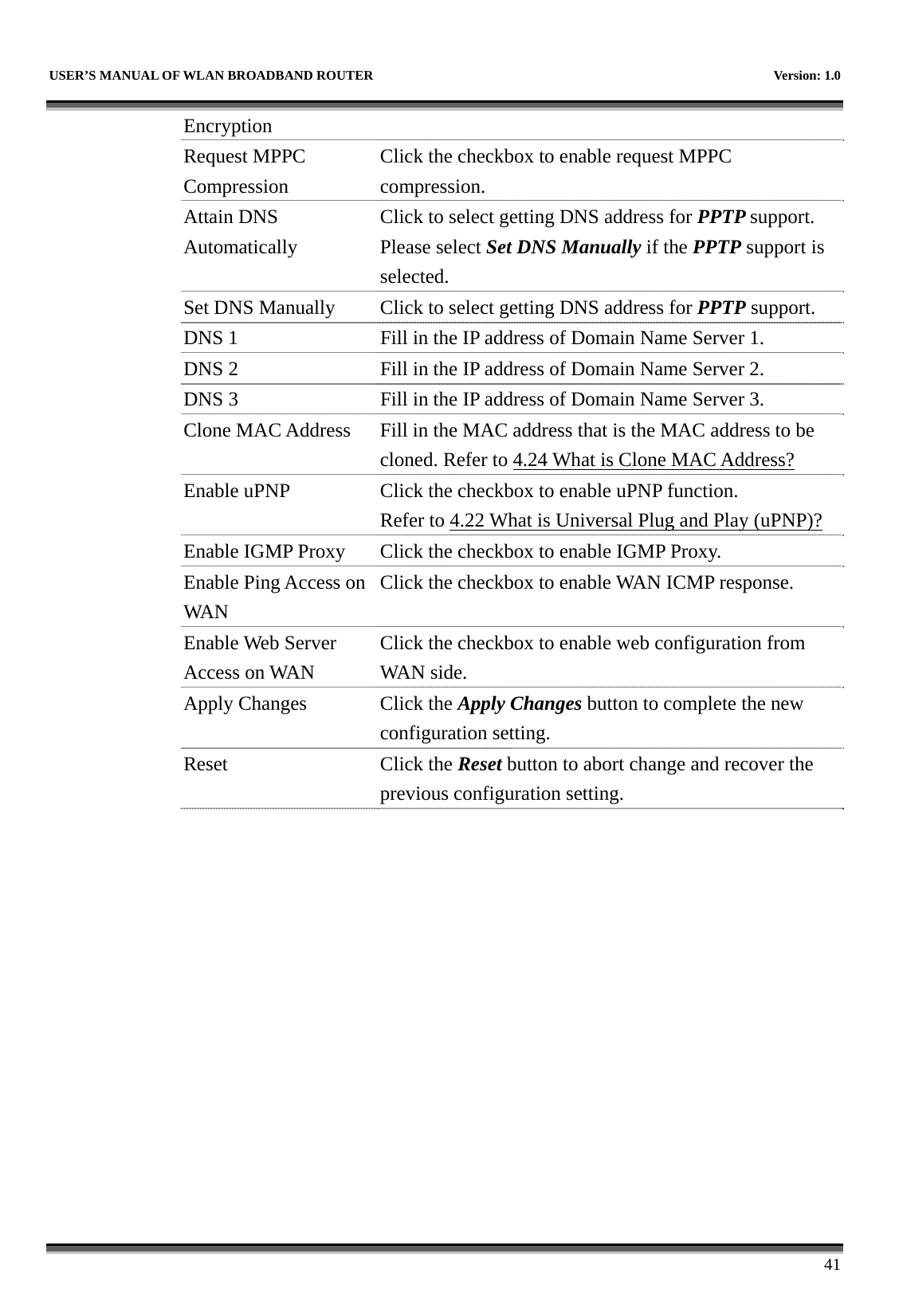
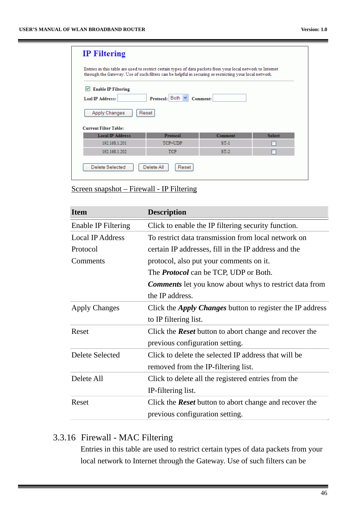
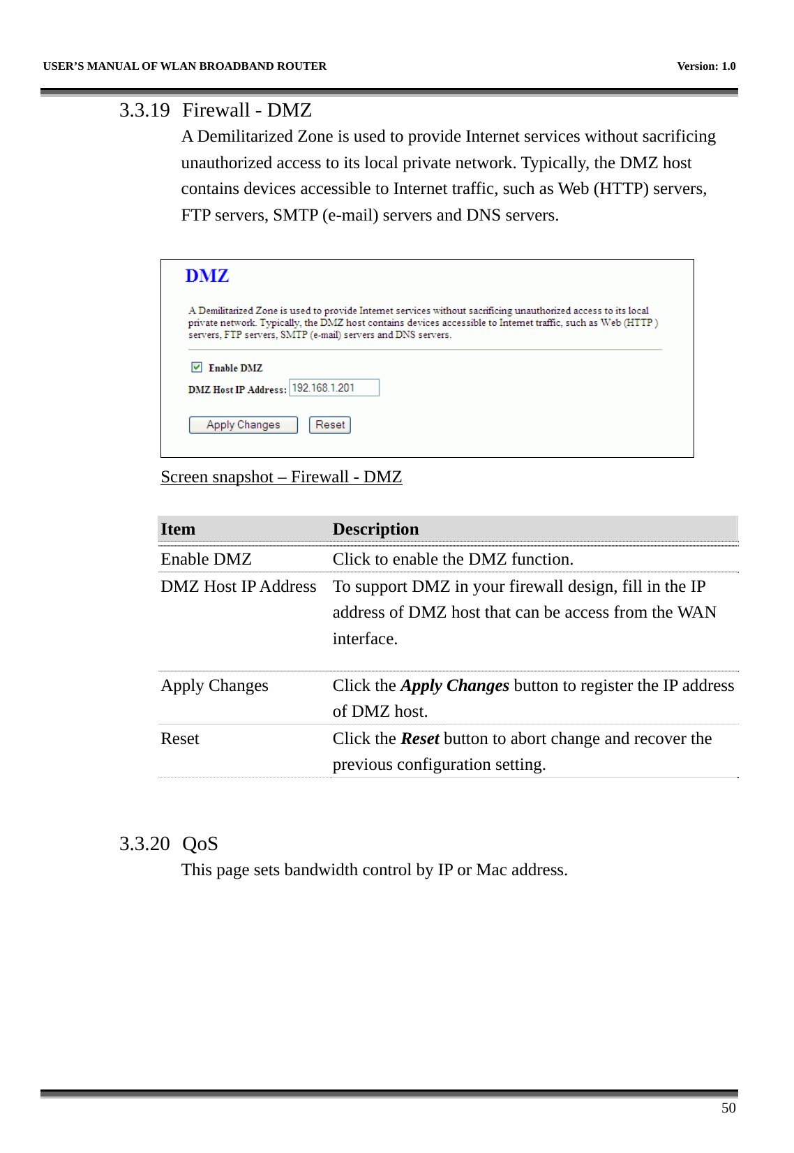
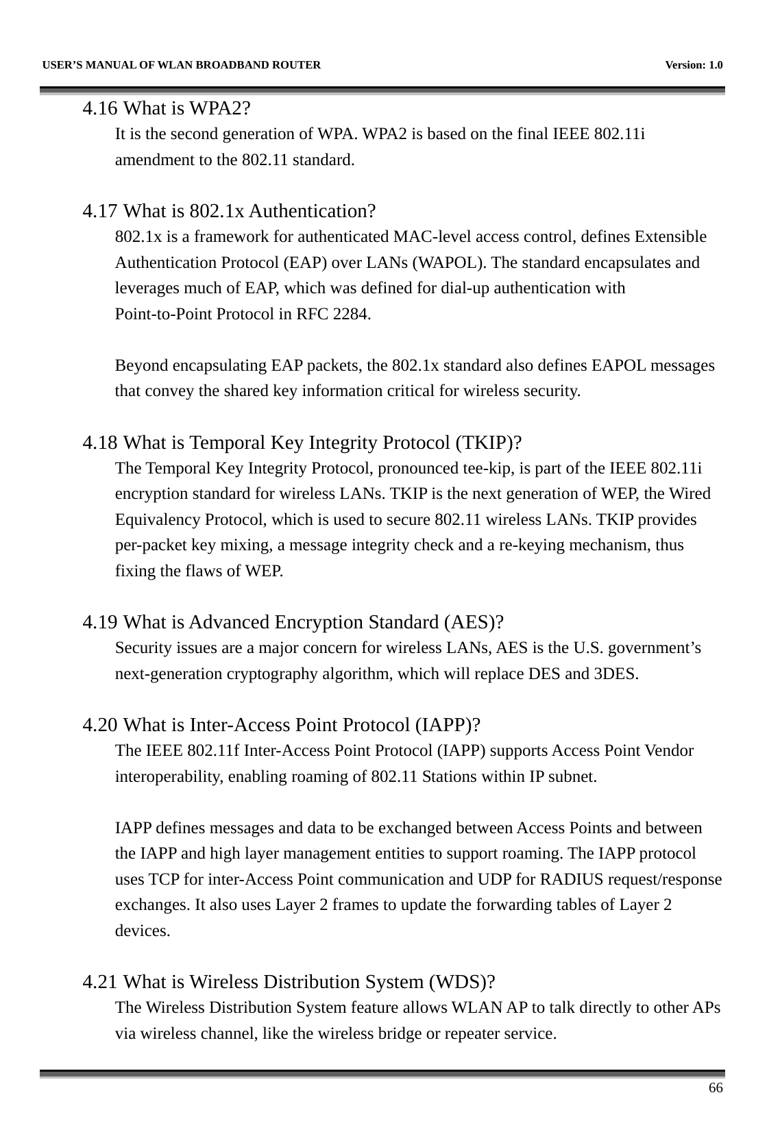
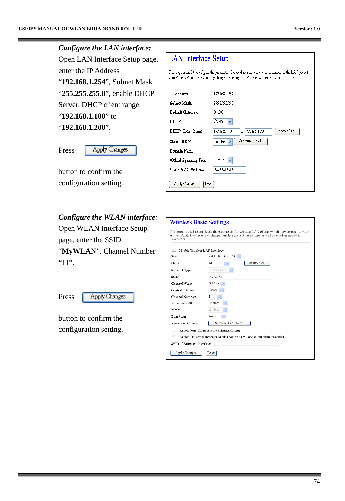
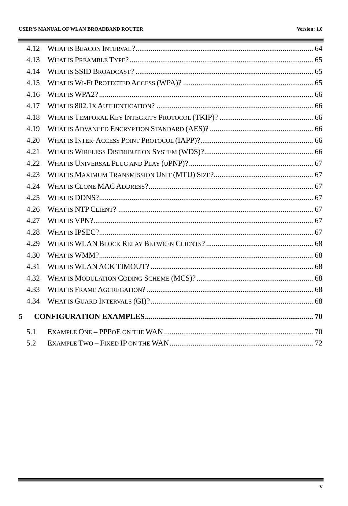
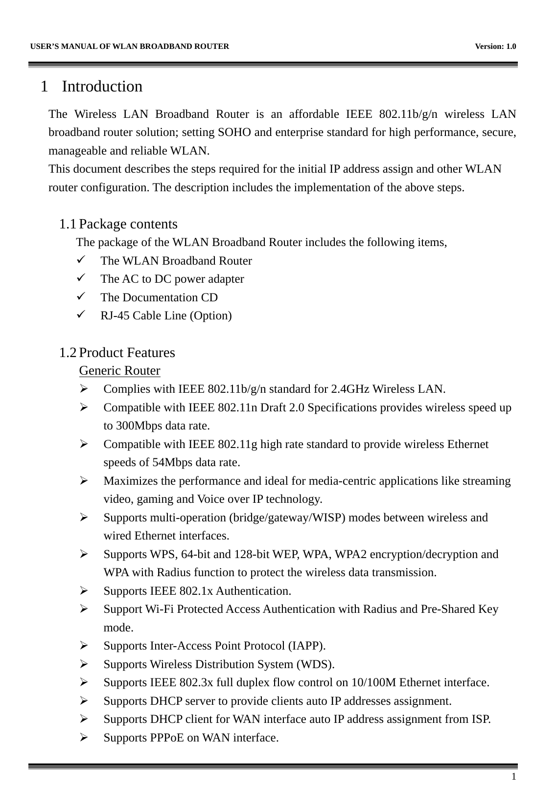
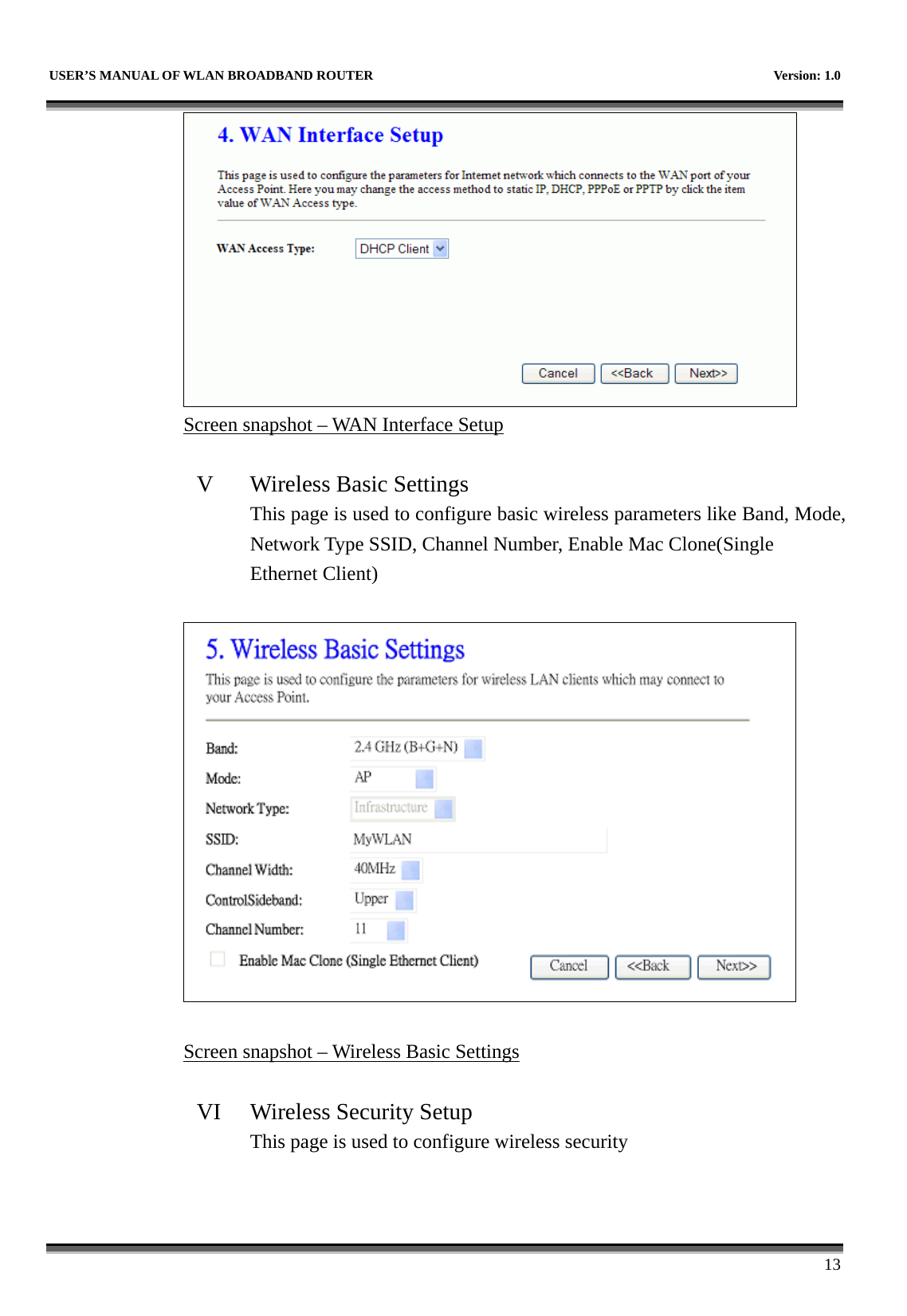
![USER’S MANUAL OF WLAN BROADBAND ROUTER Version: 1.0 29 Screen snapshot – LAN Interface Setup Item Description IP Address Fill in the IP address of LAN interfaces of this WLAN Access Point. Subnet Mask Fill in the subnet mask of LAN interfaces of this WLAN Access Point. DHCP Click to select Disabled, Client or Server in different operation mode of wireless Access Point. DHCP Client Range Fill in the start IP address and end IP address to allocate a range of IP addresses; client with DHCP function set will be assigned an IP address from the range. Show Client Click to open the Active DHCP Client Table window that shows the active clients with their assigned IP address, MAC address and time expired information. [Server mode only] Static DHCP Select enable or disable the Static DHCP function from pull-down menu. [Server mode only] Set Static DHCP Manual setup Static DHCP IP address for specific MAC address. [Server mode only]](https://usermanual.wiki/CC-and-C-Technologies/WA6212/User-Guide-1660396-Page-37.png)