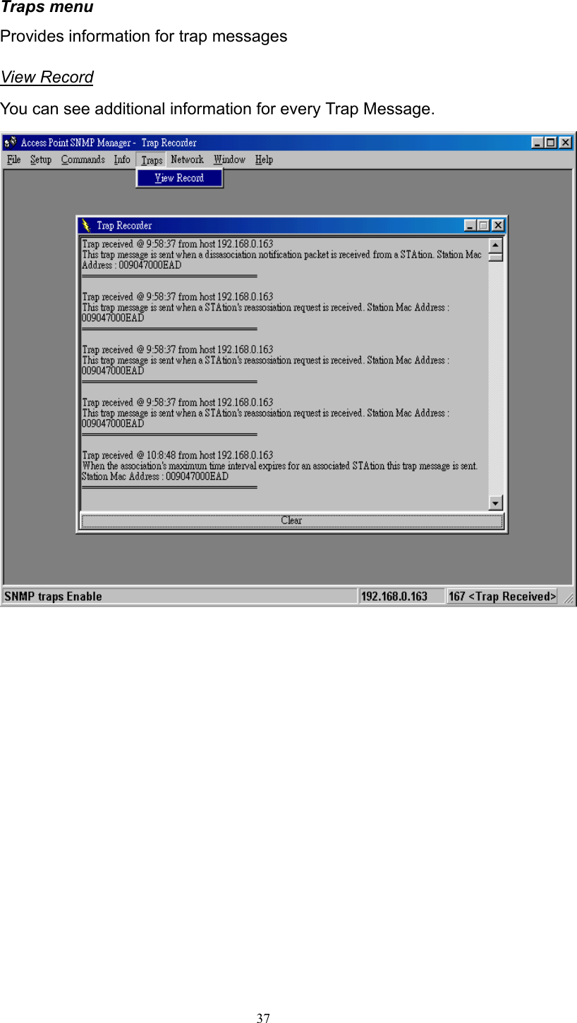
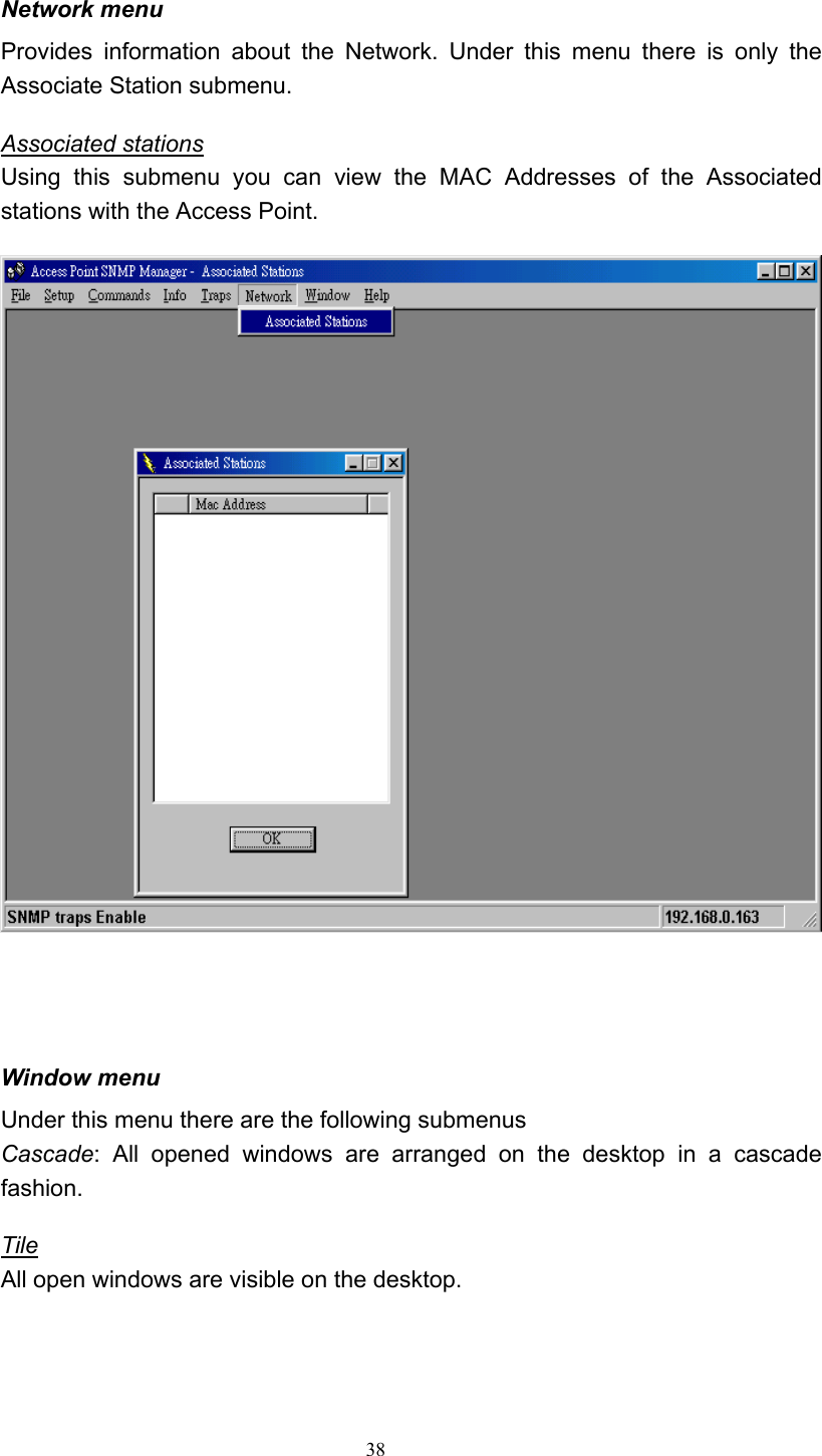
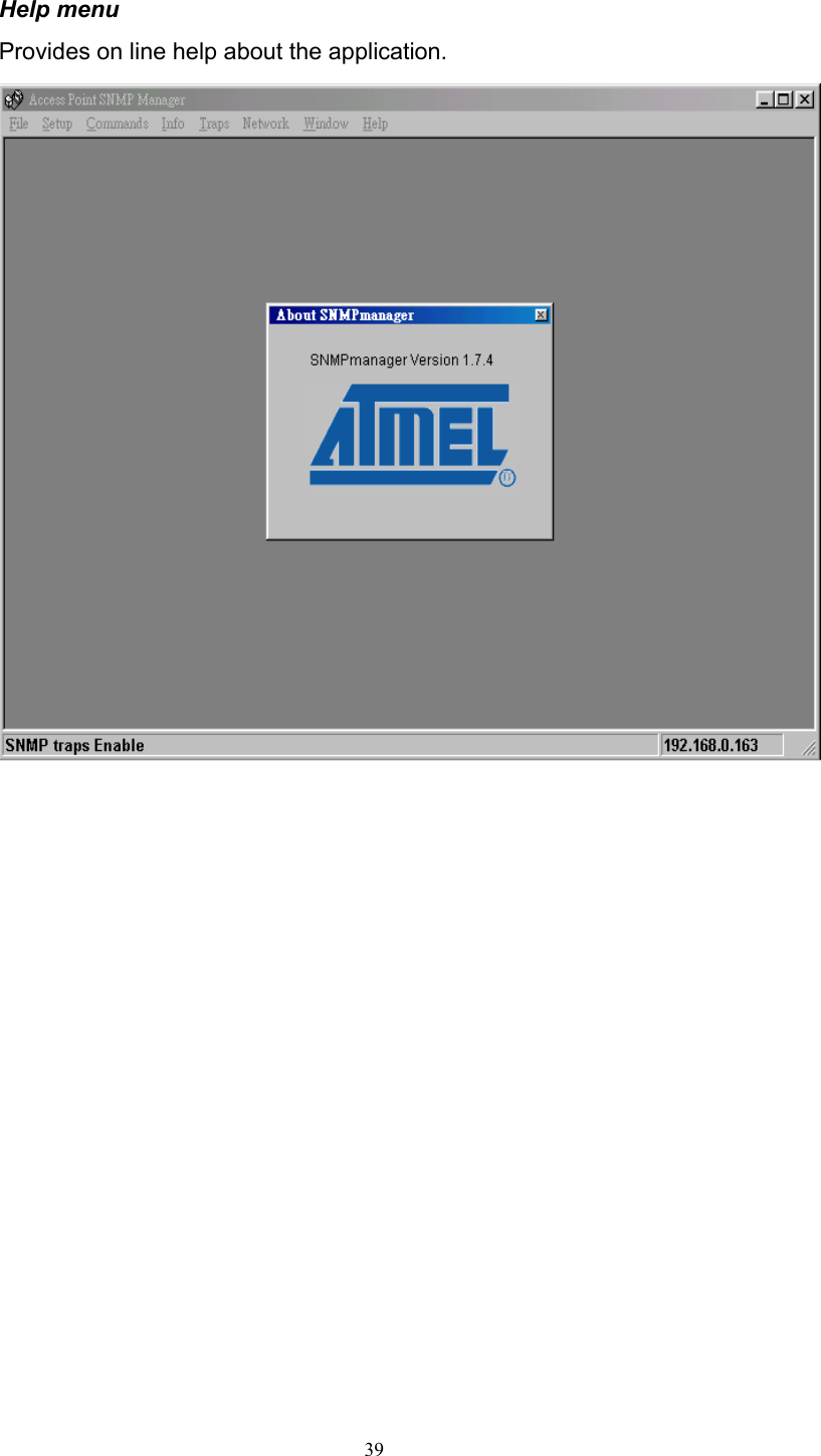
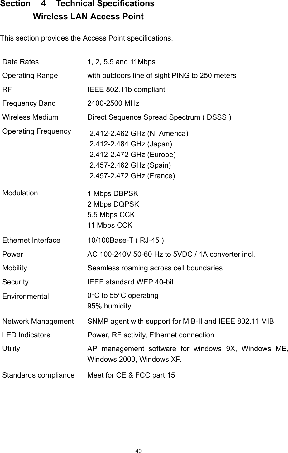
CC and C Technologies WL1300 Wireless LAN Access Point User Manual Manual

CC&C; Technologies, Inc. Wireless LAN Access Point Manual

Manual

       User’s Guide     IEEE 802.11b WLAN Bridge Access Point            Version 2.0
  2  Table of Contents  Information to the User………………..………...  3   1 Introduction……………………………………….  5  2 System Configurations…………………..………  6  3 Installation………………….…………………..…  7   3.1 Installing the SNMP Manager application..  8    3.2  Setting the IP Address……………………..  12    3.3  Using the SNMP Manager……………..…..  14   4 Technical Specifications………………………… 40   Troubleshooting…………………………………. 41  Glossary………………………………………..… 42       Product names mentioned herein may be trademarks and/or registered trademarks of their respective companies.
  3 INFORMATION TO USER   FCC INFORMATION  FCC Radiation Exposure Statement  This equipment complies with FCC radiation exposure limits set forth for an uncontrolled environment. This equipment should be installed and operated with minimum distance 20cm between the radiator & your body.   This transmitter must not be co-located or operating in conjunction with any other antenna or transmitter.  The equipment has been tested and found to comply with the limits for a Class B Digital Device, pursuant to part 15 of the FCC Rules. These limits are designed to provide reasonable protection against harmful interference in a residential installation. This equipment generates, uses and can radiate radio frequency energy and, if not installed and used in accordance with the instruction, may cause harmful interference to radio communication. However, there is no grantee that interference will not occur in a particular installation. If this equipment dose cause harmful interference to radio or television reception, which can be determined by turning the equipment off and on, the user is encouraged to try to correct the interference by one or more of the following measures:  --Reorient or relocate the receiving antenna. --Increase the separation between the equipment and receiver. --Connect the equipment into an outlet on a circuit different from that to which the receiver is connected. --Consult the dealer or an experienced radio/TV technician for help.  Notice: The Part 15 radio device operates on a non-interference basis with other devices operating at this frequency. Any changes or modification not expressly approved by the party responsible could void the user’s authority to operate the device.
  4 REGULATORY INFORMATION  The Wireless LAN Access Point must be installed and used in strict accordance with the manufacturer’s instructions. This device complies with the following radio frequency and safety standards.  USA - Federal Communications Commission (FCC) This device complies with Part 15 of FCC Rules. Operation is subject to the following two conditions: 1. This device may not cause harmful interference. 2. This device must accept any interference that may cause undesired operation.  Europe - R&TTE Directive This device complies with the specifications listed below • ETS 301-489 -1&-17 General EMC requirements for Radio equipment. • ETS 300-328 Technical requirements for Radio equipment. • EN60950 Safety Requirements for Radio equipment
  5 1  Introduction  The Access Point is a wireless LAN bridge that can act as the connection point between the Ethernet CSMA/CD protocol and the wireless CSMA/CA protocol. The Access Point can be easily integrated into your existing wireless network. In large installations, the roaming functionality provided by multiple Access Points allows wireless users to move freely throughout the facility while maintaining seamless, uninterrupted access to the network.   This document describes the steps required for the initial IP address assign and   AP configuration. The description includes the implementation of the above steps.  1.1  Installation Requirements              Before you begin installation, make sure that you have the following items: • The Access Point • The AC to DC power adapter • The Documentation CD      You will also need: • A computer that is connected to the same network as the Access Point.  1.2  System Requirements  • Desktop or laptop PC configuration through Ethernet: • Operating System: MS Windows 9X / ME / 2000 / XP.
  6 2.    Wireless LAN basics  Wireless LAN network defined by IEEE 802.11b standard committee could be configured as:   • Ad Hoc wireless LAN, or • Infrastructure wireless LAN.  Ad Hoc network is a group of notebooks with wireless LAN PC card called a BSS (Basic Service Set). These notebooks use their wireless LAN PC cards to communicate with each other, and notebooks cannot connect to the Internet.     Figure 2-1 Ad Hoc wireless network  The most obvious differentiation between Infrastructure wireless network and Ad Hoc wireless network is that the notebooks in Infrastructure wireless network can make use of the resource in the Internet through Access Point.   STA 3STA 1STA 2Access PointInternet Figure 2-2 Infrastructure wireless network  To set up your notebook’s network as the type of “Ad Hoc” or “Infrastructure” wireless network depends completely on your requirement. Generally, if your network environment has an Access Point, we recommend that you set it as “Infrastructure” to connect to the Internet.  STA 1STA 2STA 3
  7 3.  Installation  This section describes the procedures for installing the Wireless LAN Bridge Access Point under Windows 98 SE operating system.     Before You Start Before setting up your Access Point, ask your network system administrator for the following information: •    Your IP address, gateway address, and subnet mask if you’re not using a DHCP server. •    The MAC address from the label on the bottom of the Access Point. •    Your Wireless Client Name •  Your Wireless SSID •    Your computer’s unique client name and workgroup name •    For your network account, your user name and password.   Every computer on a network is identified by a unique network address. There are two methods of assigning network addresses to computer on a TCP/IP network: •  Static IP addressing •  Dynamic IP addressing (DHCP)  In networks with static IP addressing, the network administrator manually assigns an IP address to each computer. Once a static IP address is assigned, a computer uses the same IP address every time it reboots and logs on to the network. You may manually change the IP address in the Network Properties dialog box. Networks using static IP addresses are easy to set up and do not require additional network management software.  In networks with dynamic IP addressing, a DHCP server in the network dynamically assigns IP addresses to all clients every time they log on to the network. Network using dynamic IP addresses require setting up and running a DHCP Server or installing the Wingate software package.
  8 3.1    Install the SNMP Manager application        Under Windows 98 SE  Step 1 Insert the given documentation CD and then double click the MY Computer icon on your desktop. In my computer window, double click the CD Drive icon. Choose WLAN Access Point folder and double click Setup.exe to execute. It opens the welcome dialog box as shown next page then click Next.
  9 Step 2    Software License Agreement, click Yes to accept.     Step 3  Click Next to install to this folder.
  10 Step 4    Select the type of setup you prefer, then click Next.     Step 5    Setup will add program icons to the Program Folder listed below. You may type a new folder name, or select one from the Existing Folders list. Click Next to continue.
  11 Step 6  Starting Set up     Step 7  Click Finish to complete Setup.
  12 3.2    Setting the IP Address  Each station or device on your network must have a unique IP address. Following these steps to setting the IP address: Step 1    Connect an Ethernet station and the Access Point on the same subnet. The simplest way to accomplish is to connect the Access Point and the Ethernet station to the same hub. You need to check if the station IP address and the Sub-net mask are configured properly. Also the new IP address for the Access Point must correspond to the Subnet mask.  Step 2    In my computer window, double click the CD Drive icon. Choose WLAN Access Point folder then double click to execute IPConfig.exe. Then IPConfig screen displays as shown.
  13  Step 3    Type the "Access Point MAC Address" from the label on the bottom of the Access Point, type the “Config IP” address from your system administrator, and then click “OK”.   Step 3    Open a MS-DOS Prompt window and type ping followed by the IP address used in the IP Config. The IP address is assigned to the Access Point . The Access Point’s replies to the ping  confirm that the IP address was assigned correctly.   Step 4    If you get a ping reply, then the IP address has been temporarily set. In order to set it permanently you need to run SNMP Manager without powering off the Access Point.
  14 3.3    Using the SNMP Manager  On the Start Menu, choose Start->Programs->SNMP Manager.
  15 File menu When the application opens, under the File Menu there are the following submenus:  Connect to AP Using this submenu you can directly connect with the Bridge Access Point by typing its IP Address in the panel which appears and at the Community field, type the appropriate password (The default password is “public”). Additionally you have to select the User or Administrator Authority in the Authority combo-box.  User Authority allow you only to view and not to set or save changes to the Access Point Configuration, while Administrator Authority allow you to either view or set changes to the Access Point Configuration. Then press OK. If your network has a DHCP server IP Address can be automatically assigned to the Access Point.
  16 Find Access Point This submenu allows you to find and connect with an Access Point without the necessity of knowing its IP Address. Choose this submenu in order to find the Access Points available for connection. Select one of the available Access Points and press “Connect”, then appears indicating the IP Address of the selected Access Point and prompting you to select Authority and to write the appropriate password at the community field. Then press “OK”.     In case of a successful connection to the Access Point, the following window appears press “OK”
  17 When the connection has been successfully established, you get a message in the left bottom corner indicating, “Get Configuration done” and on the right bottom corner the “IP Address” of the connected Access Point.  File menu The file menu contains the following enabled submenus  Close Connection AP   Terminates the connection with the Access Point. You can find and associate with another access point by selecting the “Find Access Point” after close the connection. Download changes When all the desired values of the parameters have been set you are able to download the changes (save the changes) to the Access Point by selecting this submenu. Refresh After changing the access point setting, you can update your current display by clicking the “Fresh” function.
  18 Options Defines the polling interval according to which the SNMP Manager polls the Access Point in order to update the statistics and the Associated Stations List.
  19 Setup menu As soon as the connection has been established, you are able to start viewing or setting the Access Point parameters. Under the “Setup” menu, there are the following submenus.  Bridge Under the “Bridge” submenu, there are two options: IP configuration By choosing this option the window of appears. “IP Address” and ”IP Mask” can be modified through “IP Configuration”, if DHCP client is not enabled. If DHCP client is enabled the IP Address field displays IP Address that was dynamically assigned to the AP by the network DHCP server and the IP Mask field displays IP Mask utilized by the network DHCP server. Additional you have to select the Primary Port which is the interface that determines the DHCP server. If changes are made, you need to “Download Changes” under the “File” menu in order to save them.  Bridge IP Configuration Parameters MAC Address: Unique 48-bit, hard-coded Media Access Control address known as the station identifier. IP address: Network-assigned Internet Protocol address of the Access Point. IP Mask: Four sets of three digits that divides a network into subnet works.
  20 Filtering If the IP Routing is enabled only the IP protocol packets will pass through the WLAN and any other protocol filtered out.
  21 Wireless LAN   Under this submenu there are the following three options available. Privacy options   By choosing this option you must define the encryption key values of your choice. There are four 5 Hex digit encryption keys available if you select 64 bit WEP or there are four 13 Hex digit encryption keys available if you select 128 bit WEP. The key is enabled only if you select it in the “Default key” option. Enable the WEP (Wired Equivalent Privacy) option in order to activate WEP encryption for transmissions between the stations and the Access Point. WEP is an authentication algorithm, which protects authorized Wireless LAN users against eavesdropping. For the 64-bit encryption, each key is required to enter 5 Hex digits. For example: 11 22 33 44 55 66. The 128-bit encryption requires each key to enter 13 Hex digits. For example: 12 34 56 78 9A BC DE F0 11 22 33 44 55.    Note: The Authentication type must be the same on the wireless station and on the access point. All shared keys on the wireless station must be the same as those on the access point with which the client station is associated.               There are four 5 Hex digit encryption keys available if you select 64 bit WEP.
  22 There are four 13 Hex digit encryption keys available if you select 128 bit WEP.         Or you can select Disable.
  23 Operational Settings Using this option you can either view or modify the Wireless LAN parameters of the Access Point. These parameters are described below:   ESSID: It is an ASCII string up to 32 characters used to identify a WLAN that prevents the unintentional merging of two co-located WLANs. The ESSID value must be the same in all stations and Access Point in the extended WLAN. Select the ESSID to be used. Channel: There are 14 channels available. The channels differ from country to country. Select the channel to be used. Fragmentation threshold: The size at which packets will be fragmented. Choose a setting within a range of 256 to 2346 bytes. RTS Threshold: Minimum packet size to require an RTS (Request To Send). For packets smaller than this threshold, an RTS is not sent and the packet is transmitted directly to the WLAN. This is the option for the RTS Threshold activation.
  24 Authentication Type: Select Open System, Shared Key, or Both Open System: With this setting any station in the WLAN can associate with an   Access Point and receive and transmitted data (mull authentication). Shared Key: With this setting only stations using a shared key encryption identified by the Access Point are allowed to associate with it. Both: With this setting stations communicate with the Access Point either with or without data encryption. Preamble Type (Short/Long): Preamble is the first sub field of PPDU, which is the appropriate frame format for transmission to PHY (Physical layer). There are two options, Short Preamble and Long Preamble. The Short Preamble option improves throughput performance. Rata: By default the unit adoptively selects the highest possible rate for transmission. Select the basic rates to be used among the following options 1-2-5.5-11(Mbps),   Auto Rate Fall Back: When this is enabled the transmission rate is the optimum rate. In case of obstacles or interference, the system will automatically fall back. Regulatory Domain: The value of this field is already set and can not be modified.    If you press the Advanced button there are the following three operational modes available.
  25
  26 Access Point This mode provides two-way access between wireless stations and wired LANs. Wireless stations within the range of the Access Point device may communicate with each other via the Access Point.          Figure 3-1 Access Point
  27 Access point client This mode allows the connection of one or more remote LANs with a central LAN, creating thus an extended single virtual LAN. In this way, any station of the Remote LAN can successfully communicate with any station of the central LAN, as if all of them belonged to the same physical LAN. Wireless Stations cannot communicate directly with Access Point Clients. The Access Point conducts the designated traffic to the appropriate wired or wireless station.    Figure 3-2  Access Point Client
  28 Wireless bridge This mode allows two types of connections: a. Point to point   The Wireless Bridge can communicate with a specific Remote MAC Address. The user must define the Remote MAC Address, which is the MAC Address of the Wireless Bridge of the Remote LAN.     Figure 3-3    Wireless Bridge – Point to Point
  29 b. Point to multipoint The Wireless Bridge can communicate with any Wireless Bridge available in the same channel. When Authorization Algorithm is enabled, the Wireless Bridge can communicate with any Wireless Bridge whose MAC Addresses exists in the Authorization Table.    Figure 3-4 Wireless Bridge – Point to Multipoint   For each mode you can either view or modify the Wireless LAN parameters of the Wireless Operational Settings windows. In the Operational Mode Window there are the following parameters.
  30 Preferred BSS It is enabled only if you select the Access Point Client option. BSS corresponds to the MAC Address of the desired AP.  Remote MAC address It is enabled only if you select Point to Point. It corresponds to the MAC Address of the Wireless Bridge of the Remote LAN.
  31 Authorized MAC address For security reasons the Access Point has the ability to associate with authorized MAC Addresses stations, if the Authorization Table option is enabled. Thus, under the Authorized MAC Address option you may press the following buttons.    The “Load file” button in order to load a file with the MAC addresses that can be associated with the Access Point (Authorized MAC Addresses). The “Download” button in order to download the Authorized MAC Address to the Access Point. The “Get” button in order to get from the Access Point the Authorized MAC Addresses.
  32 Enable SNMP Traps Using this submenu you can either enable or disable SNMP traps, which are messages displayed in the right bottom corner for the main window indicating that an action related to the AP took place. Permitted messages are : Trap Reassociation: This trap message is sent when a Station’s reassociation request is received from the AP-Bridge. Trap Association: Indicates the reception of an association request packet and the sender Station’s successful association with the Wireless Bridge. Trap Disassociation: This trap message is sent when a disassociation notification packet is received from a Station. Trap Reset: This trap message is sent when the AP-Bridge resets. Trap Setting IP Address with Ping: This trap message is sent when the AP-Bridge IP address is set with the transmission of a ping message. Trap Start Up: This trap message is sent when Bridge starts up. Trap Failed to Erase Flash: This trap message is sent when Bridge fails to erase flash.
  33 Authorization Using this submenu the Administrator can change the passwords which referred to the community field for the User and the Administrator Authority.
  34 Commands menu Under this menu there are two submenus. Reset Device: you can reset the Access Point. This action takes place after a user makes configuration changes in order to initiate the changes. Restore Default: You can restore the factory default values of the Access Point.
  35 Info menu Using this menu you can view a limited number of statistics by choosing the “SNMP-Short View” of the “Change Mode” Software. There are the following submenu: Wireless Statistics: This submenu reports the statistics concerning the unit’s Wireless activity.   The meaning of the fields, concerning all the statistics, is given in the following. Unicast Transmitted Packets: The number of unicast packets successfully transmitted. Broadcast transmitted packets: The number of broadcast packets transmitted. Multicast transmitted packets: The number of multicast packets transmitted. Unicast Received Packets: The number of unicast packets that were successfully received. Broadcast Received: The number of broadcast packets that were successfully received. Multicast Received: The number of multicast packets that were successfully received.
  36 Ethernet Wireless Statistics: This submenu reports the statistics concerning the unit’s Ethernet port activity. The meaning of the fields, concerning all the statistics is given in the following.  Received Packets: Total Bytes: The number of bytes in the frames that were received. Total Packs: Total number of received packets. Packet CRC Errors: The number of packets with CRC Errors.  Transmitted Packets: Total Bytes: The number of bytes in the frames that were transmitted. Total Packs: Total number of received transmitted. Packet CRC Errors: The number of packets with CRC Errors.
  37 Traps menu Provides information for trap messages View Record You can see additional information for every Trap Message.
  38 Network menu Provides information about the Network. Under this menu there is only the Associate Station submenu. Associated stations Using this submenu you can view the MAC Addresses of the Associated stations with the Access Point.     Window menu Under this menu there are the following submenus Cascade: All opened windows are arranged on the desktop in a cascade fashion. Tile All open windows are visible on the desktop.
  39 Help menu Provides on line help about the application.
  40 Section  4  Technical Specifications  Wireless LAN Access Point  This section provides the Access Point specifications.  Date Rates  1, 2, 5.5 and 11Mbps Operating Range  with outdoors line of sight PING to 250 meters RF    IEEE 802.11b compliant Frequency Band  2400-2500 MHz Wireless Medium  Direct Sequence Spread Spectrum ( DSSS ) Operating Frequency  2.412-2.462 GHz (N. America) 2.412-2.484 GHz (Japan) 2.412-2.472 GHz (Europe) 2.457-2.462 GHz (Spain) 2.457-2.472 GHz (France) Modulation  1 Mbps DBPSK 2 Mbps DQPSK 5.5 Mbps CCK 11 Mbps CCK Ethernet Interface  10/100Base-T ( RJ-45 ) Power  AC 100-240V 50-60 Hz to 5VDC / 1A converter incl. Mobility  Seamless roaming across cell boundaries Security  IEEE standard WEP 40-bit Environmental  0°C to 55°C operating 95% humidity Network Management  SNMP agent with support for MIB-II and IEEE 802.11 MIB LED Indicators  Power, RF activity, Ethernet connection   Utility  AP management software for windows 9X, Windows ME, Windows 2000, Windows XP. Standards compliance  Meet for CE & FCC part 15
  41 Troubleshooting  Symptom: The Power and Act LEDs are off. Possible Remedy: The Power and Act LEDs should be always on after you plug in the power. If not, please check the power adaptor/cord or contact your vendor. Symptom: The Link LED is off.   Possible Remedy: The Link LED should be on after you plug in the Ethernet cable that the other end is connecting to Hub. If not, please check the RJ-45 connector/twist pair/Hub is operating properly or contact your vendor. Symptom: Can’t configure this AP. Possible Remedy: 1.  Make sure that you have installed SNMP Manager from attached CD. 2.  Check the Ethernet connection. The AP is designed to connect to hub directly or connect to PC with crossover twist pair. 3. Check the IP address. The AP left from factory with a default IP address, 192.168.0.1. If this address does not belong to the SubNetwork of the configuring terminal, then you would execute IPConfig.exe from attached CD to modify it. The MAC address could be found on the button side. Symptom: After configuration is done, but there is no any client associating with AP. Possible Remedy: 1.  Make sure there is any properly operating client in the serving area. 2.  Verify the clients and AP are sharing the same SSID and channel. 3.  Make sure they are operating under same authentication type. WEP function has to be enabled, if Shared Key Authentication is the selection, and the secret Keys have to be same in the communicating group.   4.  Position the antenna to gain the maximum RF power and make sure there is no metal objects, electron devices or cordless phone in the vicinity. Symptom: Slow or erratic performance Possible Remedy: Try change the wireless channel on the AP or move clients closer to the AP.
  42 Glossary IEEE 802.11 Standard The IEEE 802.11 Wireless LAN standards subcommittee, which is formulating a standard for the industry.    Access Point An internetworking device that seamlessly connects wired and wireless networks together.  Ad Hoc   An Ad Hoc wireless LAN is a group of computers, each with a WLAN adapter, connected as an independent wireless LAN. Ad Hoc wireless LAN is applicable at a departmental scale for a branch or SOHO operation.  BSSID A specific Ad Hoc LAN is called a Basic Service Set (BSS). Computers in a BSS must be configured with the same BSSID.  DHCP Dynamic Host Configuration Protocol - a method in which IP addresses are assigned by server dynamically to clients on the network. DHCP is used for Dynamic IP Addressing and requires a dedicated DHCP server on the network.  Direct Sequence Spread Spectrum This is the method the wireless cards use to transmit data over the frequency spectrum. The other method is frequency hopping. Direct sequence spreads the data over one frequency range (channel) while frequency hopping jumps from one narrow frequency band to another many times per second.  ESSID An Infrastructure configuration could also support roaming capability for mobile workers. More than one BSS can be configured as an Extended Service Set (ESS). Users within an ESS could roam freely between BSSs while served as a continuous connection to the network wireless stations and Access Points within an ESS must be configured with the same ESSID and the same radio channel.  Ethernet Ethernet is a 10/100Mbps network that runs over dedicated home/office wiring. Users must be wired to the network at all times to gain access.
  43  Gateway A gateway is a hardware and software device that connects two dissimilar systems, such as a LAN and a mainframe. In Internet terminology, a gateway is another name for a router. Generally a gateway is used as a funnel for all traffic to the Internet.    IEEE Institute of Electrical and Electronics Engineers  Infrastructure An integrated wireless and wired LAN is called an Infrastructure configuration. Infrastructure is applicable to enterprise scale for wireless access to central database, or wireless application for mobile workers.  ISM Band The FCC and their counterparts outside of the U.S. have set aside bandwidth for unlicensed use in the so-called ISM (Industrial, Scientific and Medical) band. Spectrum in the vicinity of 2.4 GHz, in particular, is being made available worldwide. This presents a truly revolutionary opportunity to place convenient high-speed wireless capabilities in the hands of users around the globe.  Local Area Network (LAN) A LAN is a group of computers, each equipped with the appropriate network adapter card connected by cable/air, that share applications, data, and peripherals. All connections are made via cable or wireless media, but a LAN does not use telephone services. It typically spans a single building or campus.  Network A network is a system of computers that is connected. Data, files, and messages can be transmitted over this network. Networks may be local or wide area networks.  PCMCIA Personal Computer Memory Card International Association. Also a PCMCIA card is also referred to PC Card. Protocol A protocol is a standardized set of rules that specify how a conversation is to take place, including the format, timing, sequencing and/ or error checking.
  44  Roaming  In an infrastructure network, this is when a wireless PC moves out of range of the previously connected access point and connects to a newly connected access point. Throughout the network environment where access point are deployed, PCs can always be connected regardless of where they are located or roam.  SSID A Network ID unique to a network. Only clients and Access Points that share the same SSID are able to communicate with each other. This string is case-sensitive.  Simple Network Management Protocol (SNMP) Simple Network Management Protocol is the network management protocol of TCP/IP. In SNMP, agents-which can be hardware as well as software-monitor the activity in the various devices on the network and report to the network console workstation. Control information about each device is maintained in a structure known as a management information block.  Static IP Addressing   A method of assigning IP addresses to clients on the network. In networks with Static IP address, the network administrator manually assigns an IP address to each computer. Once a Static IP address is assigned, a computer uses the same IP address every time it reboots and logs on to the network, unless it is manually changed.  Transmission Control Protocol / Internet Protocol (TCP/IP) TCP/IP is the protocol suite developed by the Advanced Research Projects Agency (ARPA). It is widely used in corporate Internet works, because of its superior design for WANs. TCP governs how packet is sequenced for transmission the network. The term “TCP/IP” is often used generically to refer to the entire suite of related protocols.  Transmit / Receive The wireless throughput in Bytes per second averaged over two seconds.  Wide Area Network (WAN) A WAN consists of multiple LANs that are tied together via telephone services and / or fiber optic cabling. WANs may span a city, a state, a country, or even the world.
  45  Wireless LAN (WLAN) A wireless LAN does not use cable to transmit signals, but rather uses radio or infrared to transmit packets through the air. Radio Frequency (RF) and infrared are the commonly used types of wireless transmission. Most wireless LANs use spread spectrum technology. It offers limited bandwidth, usually under 11Mbps, and users share the bandwidth with other devices in the spectrum; however, users can operate a spread spectrum device without licensing from the Federal Communications Commission (FCC)

Navigation menu