CC and C Technologies WL1502 802.11b WLAN Router User Manual WBR UMv2 1 English
CC&C; Technologies, Inc. 802.11b WLAN Router WBR UMv2 1 English
Contents
- 1. Users Manual 1
- 2. Users Manual 2
- 3. Users Manual 3
Users Manual 3

USER’S MANUAL OF WLAN BROADBAND ROUTER Version: 2.2
30
4 Frequently Asked Questions (FAQ)
4.1 What and how to find my PC’s IP and MAC address?
IP address is the identifier for a computer or device on a TCP/IP network. Networks
using the TCP/IP protocol route messages based on the IP address of the destination.
The format of an IP address is a 32-bit numeric address written as four numbers
separated by periods. Each number can be zero to 255. For example, 191.168.1.254
could be an IP address.
The MAC (Media Access Control) address is your computer's unique hardware number.
(On an Ethernet LAN, it's the same as your Ethernet address.) When you're connected to
the Internet from your computer (or host as the Internet protocol thinks of it), a
correspondence table relates your IP address to your computer's physical (MAC) address
on the LAN.
To find your PC’s IP and MAC address,
Open the Command program in the Microsoft Windows.
Type in ipconfig /all then press the Enter button.
Your PC’s IP address is the one entitled IP Address and your PC’s MAC address is
the one entitled Physical Address.
4.2 What is Wireless LAN?
A wireless LAN (WLAN) is a network that allows access to Internet without the need
for any wired connections to the user’s machine.
4.3 What are ISM bands?
ISM stands for Industrial, Scientific and Medical; radio frequency bands that the Federal
Communications Commission (FCC) authorized for wireless LANs. The ISM bands are
located at 915 +/- 13 MHz, 2450 +/- 50 MHz and 5800 +/- 75 MHz.
4.4 How does wireless networking work?
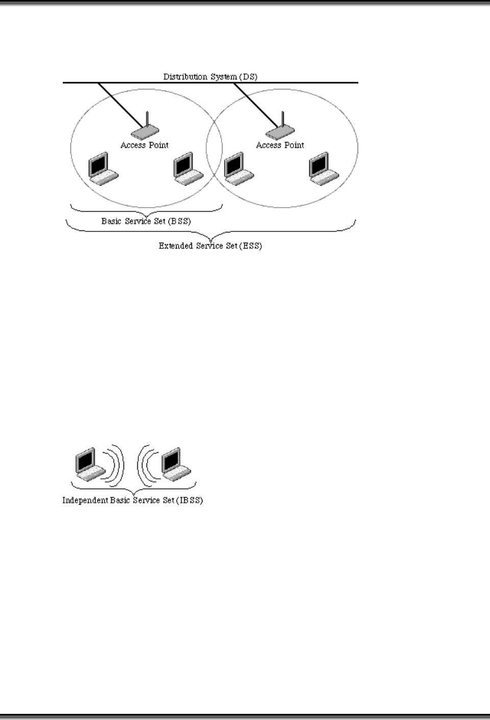
The 802.11 standard define two modes: infrastructure mode and ad hoc mode. In
infrastructure mode, the wireless network consists of at least one access point connected
to the wired network infrastructure and a set of wireless end stations. This configuration
is called a Basic Service Set (BSS). An Extended Service Set (ESS) is a set of two or
more BSSs forming a single subnetwork. Since most corporate WLANs require access
USER’S MANUAL OF WLAN BROADBAND ROUTER Version: 2.2
31
to the wired LAN for services (file servers, printers, Internet links) they will operate in
infrastructure mode.
Example 1: wireless Infrastructure Mode
Ad hoc mode (also called peer-to-peer mode or an Independent Basic Service Set, or
IBSS) is simply a set of 802.11 wireless stations that communicate directly with one
another without using an access point or any connection to a wired network. This mode
is useful for quickly and easily setting up a wireless network anywhere that a wireless
infrastructure does not exist or is not required for services, such as a hotel room,
convention center, or airport, or where access to the wired network is barred (such as for
consultants at a client site).
Example 2: wireless Ad Hoc Mode
4.5 What is BSSID?
A six-byte address that distinguishes a particular a particular access point from others.
Also know as just SSID. Serves as a network ID or name.
4.6 What is ESSID?
The Extended Service Set ID (ESSID) is the name of the network you want to access. It
is used to identify different wireless networks.

USER’S MANUAL OF WLAN BROADBAND ROUTER Version: 2.2
32
4.7 What are potential factors that may causes interference?
Factors of interference:
Obstacles: walls, ceilings, furniture… etc.
Building Materials: metal door, aluminum studs.
Electrical devices: microwaves, monitors and electrical motors.
Solutions to overcome the interferences:
Minimizing the number of walls and ceilings.
Position the WLAN antenna for best reception.
Keep WLAN devices away from other electrical devices, eg: microwaves,
monitors, electric motors, … etc.
Add additional WLAN Access Points if necessary.
4.8 What are the Open System and Shared Key authentications?
IEEE 802.11 supports two subtypes of network authentication services: open system and
shared key. Under open system authentication, any wireless station can request
authentication. The station that needs to authenticate with another wireless station sends
an authentication management frame that contains the identity of the sending station.
The receiving station then returns a frame that indicates whether it recognizes the
sending station. Under shared key authentication, each wireless station is assumed to
have received a secret shared key over a secure channel that is independent from the
802.11 wireless network communications channel.
4.9 What is WEP?
An optional IEEE 802.11 function that offers frame transmission privacy similar to a
wired network. The Wired Equivalent Privacy generates secret shared encryption keys
that both source and destination stations can use to alert frame bits to avoid disclosure to
eavesdroppers.
WEP relies on a secret key that is shared between a mobile station (e.g. a laptop with a
wireless Ethernet card) and an access point (i.e. a base station). The secret key is used to
encrypt packets before they are transmitted, and an integrity check is used to ensure that
packets are not modified in transit.
4.10 What is Fragment Threshold?
The proposed protocol uses the frame fragmentation mechanism defined in IEEE 802.11
to achieve parallel transmissions. A large data frame is fragmented into several

USER’S MANUAL OF WLAN BROADBAND ROUTER Version: 2.2
33
fragments each of size equal to fragment threshold. By tuning the fragment threshold
value, we can get varying fragment sizes. The determination of an efficient fragment
threshold is an important issue in this scheme. If the fragment threshold is small, the
overlap part of the master and parallel transmissions is large. This means the spatial
reuse ratio of parallel transmissions is high. In contrast, with a large fragment threshold,
the overlap is small and the spatial reuse ratio is low. However high fragment threshold
leads to low fragment overhead. Hence there is a trade-off between spatial re-use and
fragment overhead.
Fragment threshold is the maximum packet size used for fragmentation. Packets larger
than the size programmed in this field will be fragmented.
If you find that your corrupted packets or asymmetric packet reception (all send packets,
for example). You may want to try lowering your fragmentation threshold. This will
cause packets to be broken into smaller fragments. These small fragments, if corrupted,
can be resent faster than a larger fragment. Fragmentation increases overhead, so you'll
want to keep this value as close to the maximum value as possible.
4.11 What is RTS (Request To Send) Threshold?
The RTS threshold is the packet size at which packet transmission is governed by the
RTS/CTS transaction. The IEEE 802.11-1997 standard allows for short packets to be
transmitted without RTS/CTS transactions. Each station can have a different RTS
threshold. RTS/CTS is used when the data packet size exceeds the defined RTS
threshold. With the CSMA/CA transmission mechanism, the transmitting station sends
out an RTS packet to the receiving station, and waits for the receiving station to send
back a CTS (Clear to Send) packet before sending the actual packet data.
This setting is useful for networks with many clients. With many clients, and a high
network load, there will be many more collisions. By lowering the RTS threshold, there
may be fewer collisions, and performance should improve. Basically, with a faster RTS
threshold, the system can recover from problems faster. RTS packets consume valuable
bandwidth, however, so setting this value too low will limit performance.
4.12 What is Beacon Interval?
In addition to data frames that carry information from higher layers, 802.11 includes
management and control frames that support data transfer. The beacon frame, which is a
type of management frame, provides the "heartbeat" of a wireless LAN, enabling

USER’S MANUAL OF WLAN BROADBAND ROUTER Version: 2.2
34
stations to establish and maintain communications in an orderly fashion.
Beacon Interval represents the amount of time between beacon transmissions. Before a
station enters power save mode, the station needs the beacon interval to know when to
wake up to receive the beacon (and learn whether there are buffered frames at the access
point).
4.13 What is Preamble Type?
There are two preamble types defined in IEEE 802.11 specification. A long preamble
basically gives the decoder more time to process the preamble. All 802.11 devices
support a long preamble. The short preamble is designed to improve efficiency (for
example, for VoIP systems). The difference between the two is in the Synchronization
field. The long preamble is 128 bits, and the short is 56 bits.
4.14 What is SSID Broadcast?
Broadcast of SSID is done in access points by the beacon. This announces your access
point (including various bits of information about it) to the wireless world around it. By
disabling that feature, the SSID configured in the client must match the SSID of the
access point.
Some wireless devices don't work properly if SSID isn't broadcast (for example the
D-link DWL-120 USB 802.11b adapter). Generally if your client hardware supports
operation with SSID disabled, it's not a bad idea to run that way to enhance network
security. However it's no replacement for WEP, MAC filtering or other protections.
USER’S MANUAL OF WLAN BROADBAND ROUTER Version: 2.2
35
5 Configuration Examples
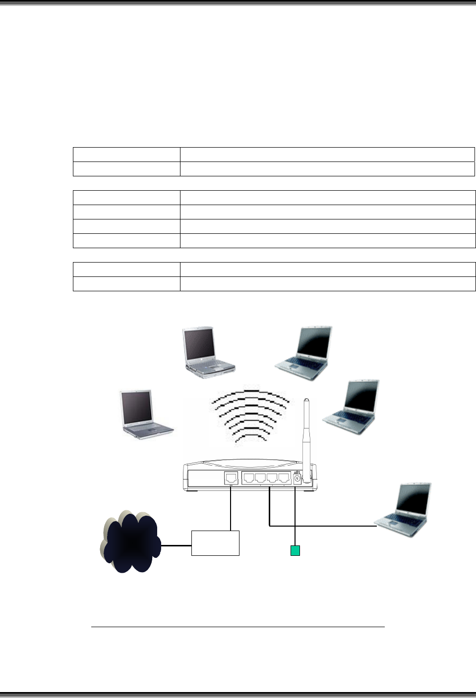
5.1 Example One – PPPoE on the WAN
Sales division of Company ABC likes to establish a WLAN network to support mobile
communication on sales’ Notebook PCs. MIS engineer collects information and plans
the WLAN Broadband Router implementation by the following configuration.
WAN configuration:
PPPoE
User Name H890123456
Password PW192867543210
LAN configuration
IP Address 192.168.1.254
Subnet Mask 255.255.255.0
Default Gateway 0.0.0.0
DHCP Client Range 192.168.1.100 – 192.168.1.131
WLAN configuration
SSID SDWLAN
Channel Number 1
Internet xDSL/ CM
Power adapter
Ethernet
Cable Ethernet cable
SSID: SDWLAN
Channel: 1
DHCP client
SSID: SDWLAN
Channel: 1
DHCP client
SSID: SDWLAN
Channel: 1
DHCP client
SSID: SDWLAN
Channel: 1
DHCP client
DHCP client
Bridge mode
PPPoE connection parameters:
User Name: H890123456
Passwrod: pw192867543210
SSID: SDWLAN
Channel: 1
DHCP range: 192.168.1.100 to 192.168.1.131
Figure 3 – Configuration Example One – PPPoE on the WAN
USER’S MANUAL OF WLAN BROADBAND ROUTER Version: 2.2
36
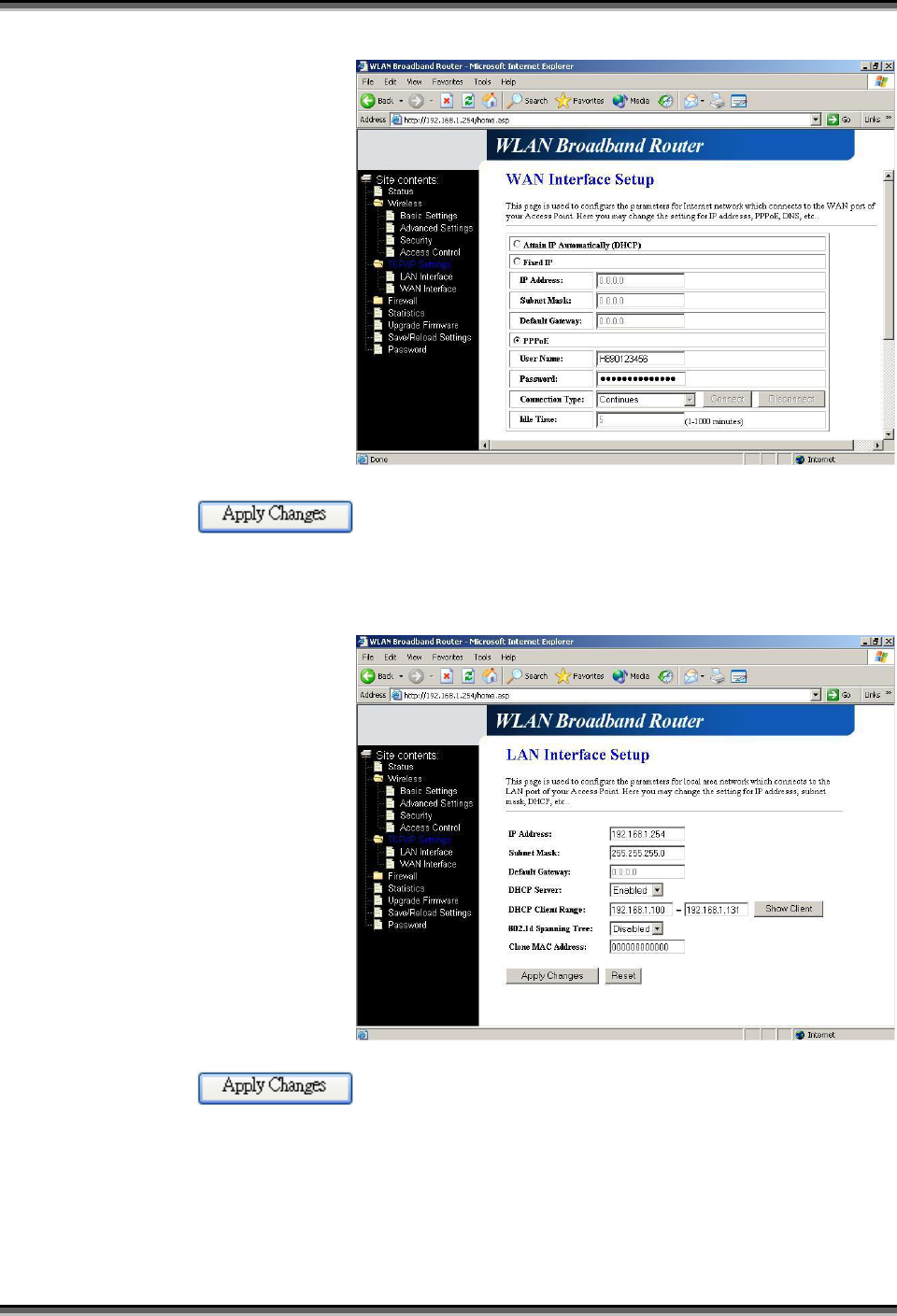
Configure the WAN interface:
Open WAN Interface
Setup page, select
PPPoE then enter the
User Name
“H890123456” and
Password
“PW192867543210”,
the password is
encrypted to display on
the screen.
Press button to confirm the configuration setting.
Configure the LAN interface:
Open LAN Interface
Setup page, enter the IP
Address
“192.168.1.254”,
Subnet Mask
“255.255.255.0”,
Default Gateway
“0.0.0.0”, enable DHCP
Server, DHCP client
range “192.168.1.100”
to “192.168.1.131”.
Press button to confirm the configuration setting.
USER’S MANUAL OF WLAN BROADBAND ROUTER Version: 2.2
37
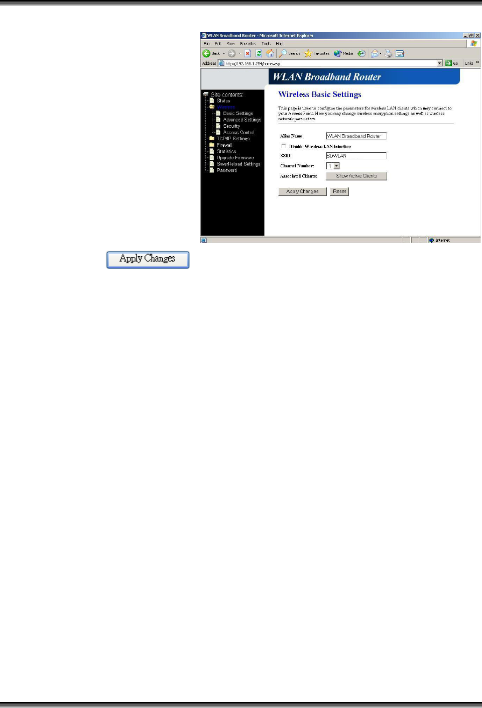
Configure the WLAN interface:
Open WLAN Interface
Setup page, enter the
SSID “SDWLAN”,
Channel Number “1”.
Press button to confirm the configuration setting.
USER’S MANUAL OF WLAN BROADBAND ROUTER Version: 2.2
38
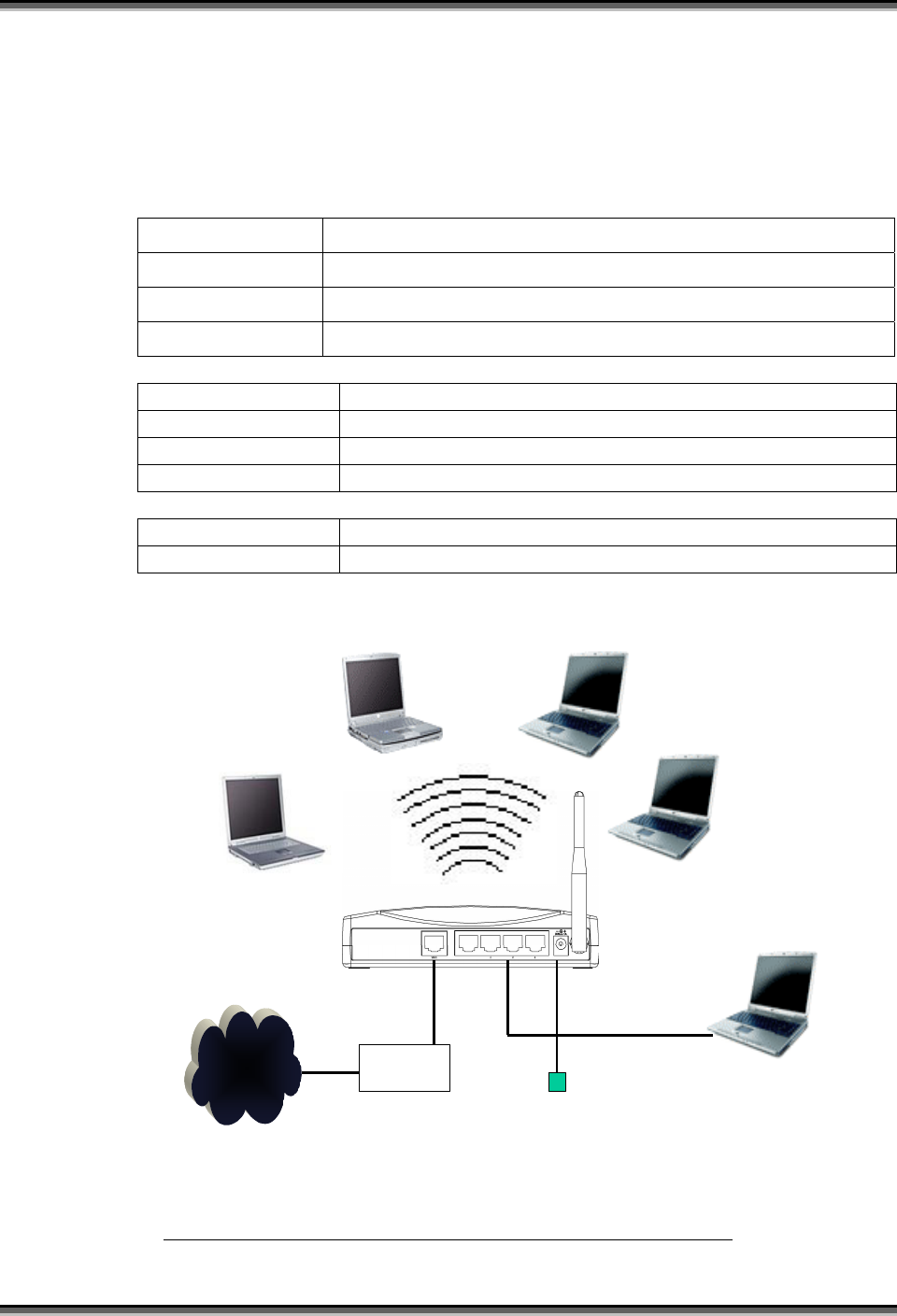
5.2 Example Two – Fixed IP on the WAN
Company ABC likes to establish a WLAN network to support mobile communication
on all employees’ Notebook PCs. MIS engineer collects information and plans the
WLAN Broadband Router implementation by the following configuration.
WAN configuration:
Fixed IP
IP Address 192.168.2.254
Subnet Mask 255.255.255.0
Default Gateway 192.168.2.10
DNS Address 168.95.1.1
LAN configuration
IP Address 192.168.1.254
Subnet Mask 255.255.255.0
Default Gateway 192.168.2.254
DHCP Client Range 192.168.1.100 – 192.168.1.131
WLAN configuration
SSID MyWLAN
Channel Number 6
Internet xDSL/ CM
Power adapter
Ethernet
Cable
Ethernet cable
SSID: MyWLAN
Channel: 6
DHCP client
SSID: MyWLAN
Channel: 6
DHCP client
SSID: MyWLAN
Channel: 6
DHCP client
SSID: MyWLAN
Channel: 6
DHCP client
DHCP client
Router mode
SSID: MyWLAN
Channel: 6
DHCP range: 192.168.1.100 to 192.168.1.131
192.168.2.10/ 255.255.255.0
192.168.2.254/ 255.255.255.0
Figure 4 – Configuration Example Two – Fixed IP on the WAN
USER’S MANUAL OF WLAN BROADBAND ROUTER Version: 2.2
39
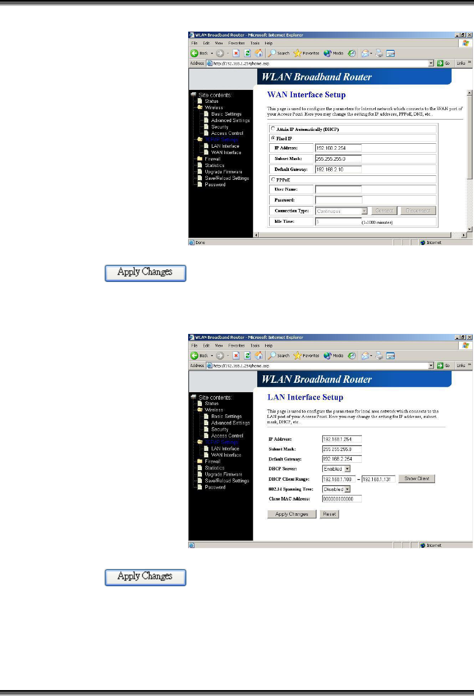
Configure the WAN interface:
Open WAN Interface
Setup page, select Fixed
IP then enter IP Address
“192.168.2.254”,
subnet mask
“255.255.255.0”,
Default gateway
“192.168.2.10”.
Press button to confirm the configuration setting.
Configure the LAN interface:
Open LAN Interface
Setup page, enter the IP
Address
“192.168.1.254”,
Subnet Mask
“255.255.255.0”,
Default Gateway
“192.168.2.254”, enable
DHCP Server, DHCP
client range
“192.168.1.100” to
“192.168.1.131”.
Press button to confirm the configuration setting.
USER’S MANUAL OF WLAN BROADBAND ROUTER Version: 2.2
40
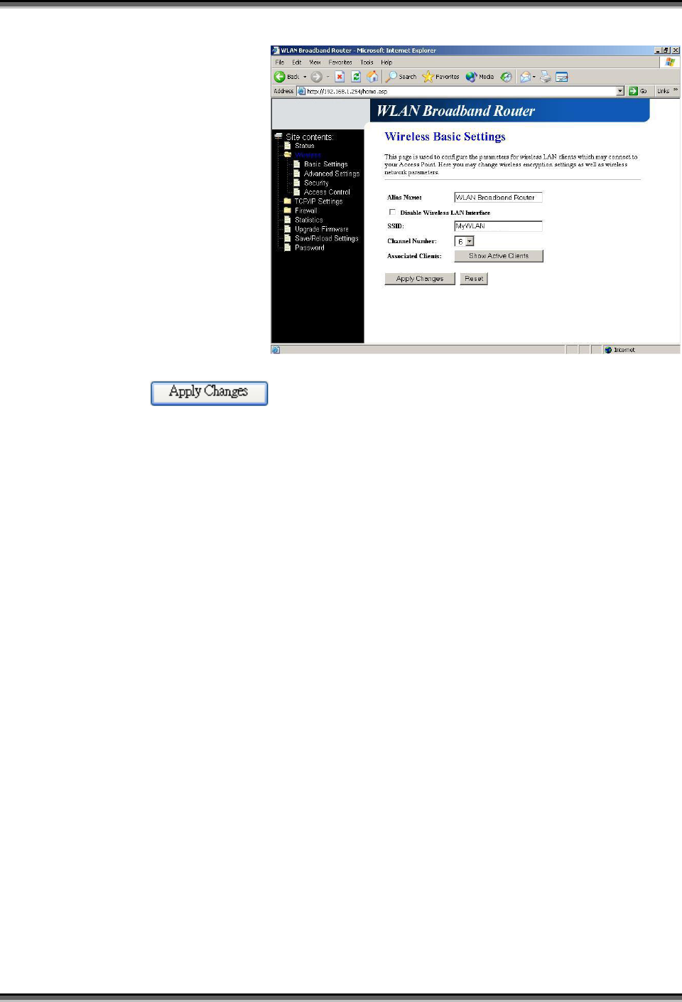
Configure the WLAN interface:
Open WLAN Interface
Setup page, enter the
SSID “MyWLAN”,
Channel Number “6”.
Press button to confirm the configuration setting.