CCP PG-2401 2.4G Basic Radio Control System with Servo Unit User Manual Users manual
CCP Co., Ltd. 2.4G Basic Radio Control System with Servo Unit Users manual
CCP >
Users manual

It is important that you read and understand the instructions completely before use.
Misuse of this product could cause fire or injury.
Please keep this manual for future reference in order to prevent accidents.
This product is not recommended for use by children less than 14 years of age without
adult supervision.
Please read before use
This product is designed only for radio control ground models. Not recommended for use in
boats or flying models.
The manufacturer and distributor will accept no responsibility, expressed or implied, for accidents or
injuries caused as a result of dismantling or modification.
Please plug the connector into the receiver firmly and in the correct direction. Do not damage the
cable, break, modify, pull or twist it. When pulling out the connector, it should always be pulled
by its housing not by the cable.
Keep fuel and exhaust away from plastic parts. This may cause damage or malfunction.
Attention during use
Any water ingress or moisture may cause damage or malfunction. Do not use in the rain or expose
equipment to water.
Always drive an RC car with care and do not use in:
1Crowded places, near other people, especially small children.
2Confined spaces. In the wet, in fog or at night time.
3When tried, sick, medication, under influence of alcohol or any other condition which may
affect your ability to control the model.
Changes to the TX settings should only be made when the engine has stopped
(or motor wires disconnected).
Always turn on the TX first and then the power to the RX.
Reverse this procedure when turning off i.e. turn off the RX and then the TX.
Always check the fail safe function on Nitro cars in prior to running the model.
Never loose sight of your model which could result in damage or injury.
After the smoke has cleared,
check if the item has cooled.
1
2
3
4
5
Stop the engine and motor of the model.
Turn the receiver switch off.
Turn the transmitter switch off.
Remove the battery and contact your supplier
.
That changes or modifications not expressly approved by the party responsible for compliance
could void the user's authority to operate the equipment.
In the event of
SAFETY GUIDELINES
In the event of
Smoke
Burning smell
Strange sound
Water or any liquid
coming into contact
with the product
Or if it is dropped
or damaged.
1
Attention after use
Do not keep your model
1
In an extremely hot or cold place (more than 40 degree, less than -10 degree C.)
2
In direct sunlight
3
Humid atmosphere
4
Avoid excessive vibration
5
Dusty environment
!
Exposing this equipment to such conditions, may cuase the damage, degradation or malfunction.
Keep the model away from children.
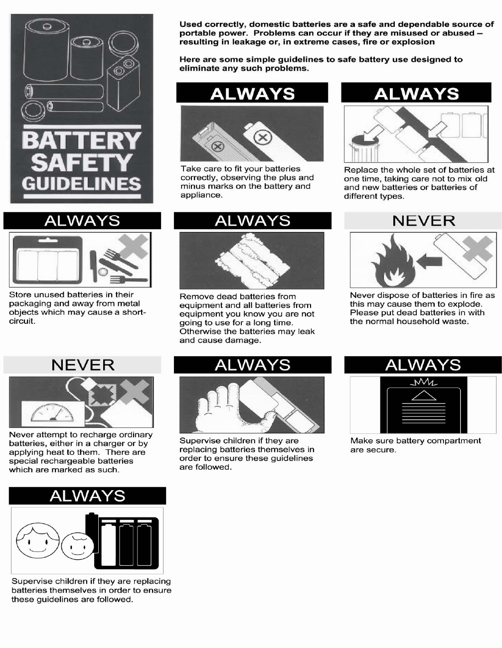
Essential information regarding batteries
When not in use always disconnect batteries. Leaving batteries connected can be very
dangerous resulting in explosion or fire.
Never short-circuit the connecter terminal. This can cause explosion or fire.
Only ever charge TX batteries with their own charger.
Do not dismantle batteries. Batteries contain dangerous chemicals.
Do not immerse batteries in water.
Always ensure correct polarity.
Note that alkaline batteries cannot be recharged. Make sure that batteries are
rechargeable items before you charge them.
Do not mix different types of batteries.
Be careful of the sharp edges inside the battery box.
Battery disposal
Do not dispose the battery with other general garbage.
Disposal should be in accordance with your Country's legislation.
Isolate battery terminals with insulating tape before disposal.
Rechargeable batteries must be recycled.
Please note that short-circuiting batteries can cause fire
or electric shock.
2.4GHz CHARACTERISTICS
This system allows the transmitter and receiver to search for available bands empty band and lock
on to one of 76 available on the 2.4GHz frequency. This eliminates the traditional method of using
crystals.
Each transmitter hold its own I.D. Receivers never operate with other transmitters. It also is
not necessary to switch on TX and then RX as with traditional radio system.
The control signal is high speed digital and it is recognized by RX CPU. In a fully charged state
function.
the car should be in full control at all times. You can also select hold function or fail safe
In case of battery leakage Avoid eye contact, which may cause blindness. Rinse
eyes immediately with water and consult your doctor.
2
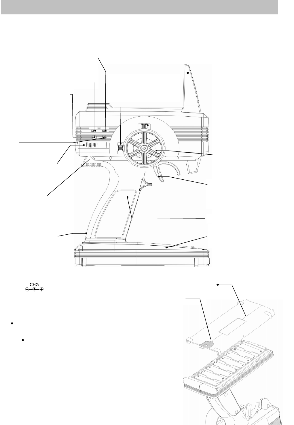
EXTERNAL VIEW OF TRANSMITTER
When each lever is operated the action is confirmed with the sound of a buzzer beep.
You can hear this click sound when the setting position is changed.
HOLE FOR STRAP
HOW TO INSTALL THE BATTERIES
Push the finger point ,then slide the battery cover
Pay close attention to polarity of
batteries when installing.
!
Incorrectl
y
installed batteries
may cause damage to the
radio.
!
Do not mix different t
yp
es
of batteries.
! Never allow batteries to leak.
Clean surfaces and avoid skin contact.
Then replace with new batteries.
TRANSMITTER
STEERING WHEEL(CH-1)
Turn to left and right
LED
BATTERY BOX
Be careful of sharp edges of the
battery terminals or springs.
TX SETTING BUTTON
Switch the transmitter on
by
pushing the set up button.
The LED will start to flash
slowl
y
indicatin
g
that it is in
POWER SWITCH
Slide to right to switch on.
Slide to left to switch off. THROTTLE TRIGGER(CH-2)
Squeeze the trigger to
accelerate. Push the trigger to
en
g
a
g
e brakes or reverse.
ANTENNA
!
Please handle with care to
reduce risk of damage.
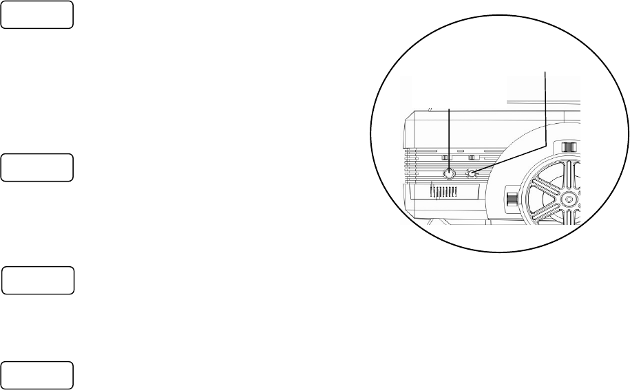
THROTTLE TRIM
LEVER
Operates up and down
STEERING TRIM LEVER
Operates left and right
adjustment
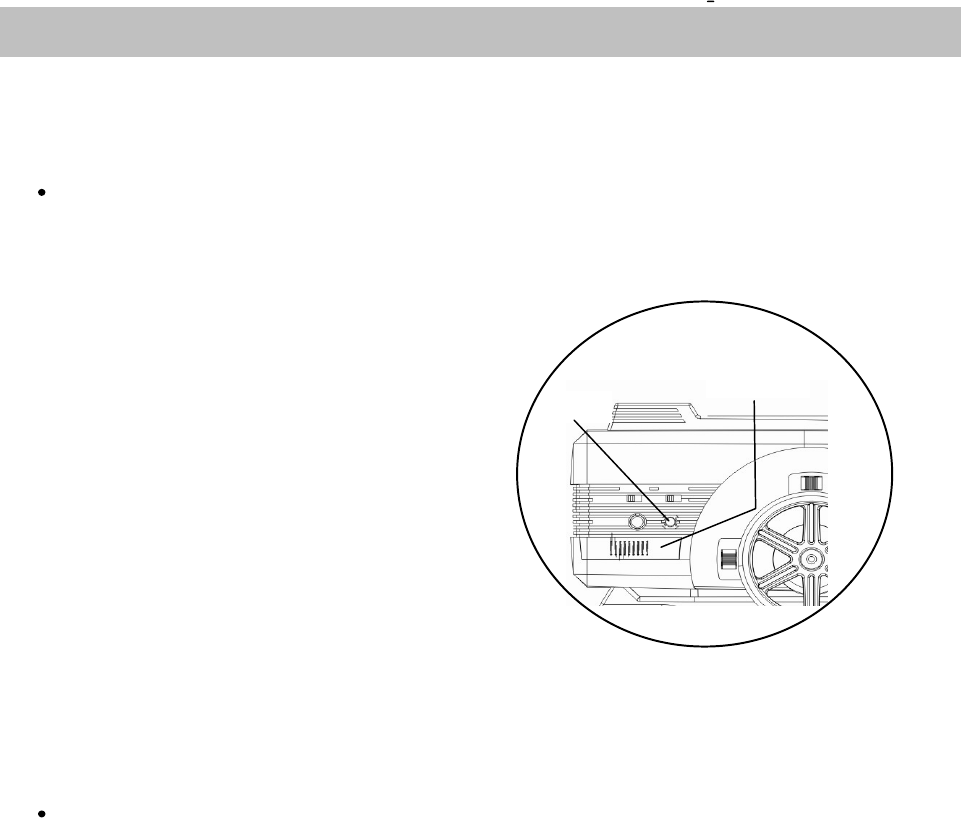
CHARGING JACK GRIP
THROTTLE REVERSE SWITCH
Switch between throttle forward and
backward direction
STEERING REVERSE SWITCH
Switch between steering left and right
direction
IMPORTANT!
Only charge batteries capable
of being recharged and
marked rechargeable.
Serious damage to equipment
will result in trying to charge
non-rechargeable cells. Battery cover
Finger point
3
Transmitter
When the Transmitter is switched on it automatically
starts to search for free a band.
Once it is located it locks to it during this search.
The LED will initially blink and then
change to a constant light once it has
completed this procedure and secured a band.
Attention:
When there are many 2.4GHz wave devices
around, the search time may be longer.
Receiver
When the receiver is switched on, it will also look for the transmitter which has the same ID. When it
finds the same ID, the LED will flash and when the band is fixed, the LED changes to a constant
light. ( Just like the Transmitter )
Attention:
When there are other 2.4GHz wave devices around, the scanning time may take longer.
If the receiver cannot locate the transmitter's signal or suffers from interference, the steering servo
will not function.
When the fail-safe function is off, the signal to the throttle channel is cut off.
This means that the speed controller throttle function or alternatively the throttle servo will not operat
e
Both functions will revert to normal operation when the receiver obtains the correct signal.
If the receiver cannot obtain the signal from the transmitter after one second, the receiver will
automatically scan the bands to find the transmitter signal.
ID registration and setting of fail safe function
SAFE SET UP PROCEDURE
POWER
SWITCH
LED
4
Attention:
Set up should be conducted in an area free from interference by other 2.4GHz transmitters.
Push the set up button on the front
of the transmitter, then switch the
transmitter on. Transmitter will output
the electrical wave under this setting
mode. Output power will be given weakly
to avoid interference to others.
In this case, LED will flash slowly.
Push the set up button on the receiver
and then switch receiver on. Release
the set up button. The receiver
will enter set up mode and transmitter ID
is registered to the receiver.
You can set the failsafe function ON or OFF by repeatedly pushing and releasing the
set up button on the receiver.
LED is ON : Fail-safe function ON
LED is OFF : Fail-safe function OFF
To set the position of the servo in failsafe mode, first press the receiver button
so that the LED is off. Move the trigger to the desired failsafe position.
Push the receiver set up button so that the LED is on and this position will be memorized
in the receiver. If the TX trigger is not moved, the position of the trigger will be memorised
in neutral.
Attention:
After the ID and fail safe are set, switch the transmitter and receiver off and restart both.
Check that all functions are working correctly before operating the model.
Attention:
When adjusting failsafe function for nitro models, set failsafe function to apply brakes
in a setting that will allow the model to stop in a safe fashion.
Attention:
If another 2.4GHz radio is being set up nearby, your TX will not enter set up mode.
Checking Fail Safe Function ON/OFF
Switch the transmitter off and leave the receiver on, the receiver start to search and LED will
start to flash. If you activated the fail-safe function and it is ON, the servo will return to the position
saved in memory and if failsafe function is OFF, the servo will be in neutral position.
Step 1
Step 2
Step 3
Step 4
Transmitter
setting up
button
LED
5
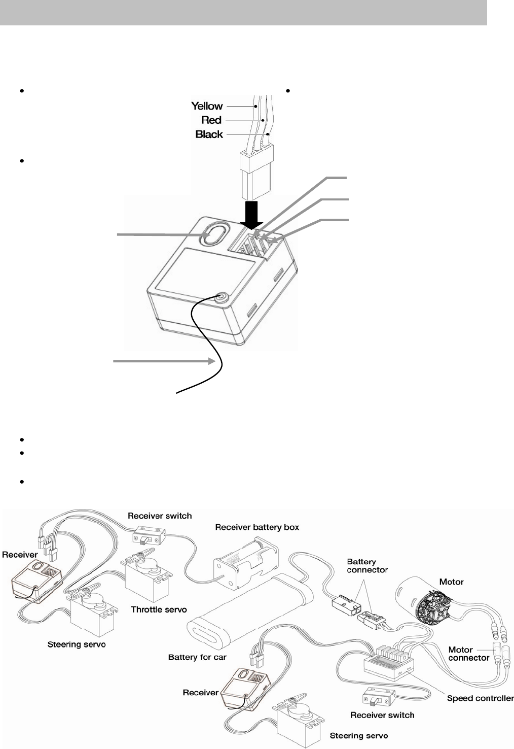
Parts identification
Connecter must be fitted firmly. If The plug must only be fitted facing one
the connecter is not fixed direction. Always ensure that the black cable
correctly, it may come lead wire is facing outwards when the servo
disconnected and cause vehicle and switch harness are connected to
to go out of control. the receiver.
When the connecter is
removed, pull it by the housing Battery Switch Harness
not by the cable.
CH1 Steering Servo
CH2 Speed Controller or
Set up button Throttle Servo
Antenna lead
Receiver Connection
Connect the battery and motor with correct polarity.(* Incorrect polarity causes product damage)
The manufacturer and distributor will accept no responsibility, expressed or implied, for problems
caused by usage of Non-genuine parts.
When you have finished driving your car, remove batteries to prevent danger of
activation if accidentally switched on.
RECEIVER
6
Caution when installing the receiver
Do not install the receiver in a low position of a large scale model. The antenna wire must
protrude sufficiently to receive a clear signal. Furthermore, if the receiver is surrounded by
metal components (i.e. a roll cage) the signal may be subject to interference. In these
instances the receiver should be repositioned at the front or on the upper sections of the model.
To avoid direct vibration during driving, receiver should be fixed in a place which will not touch other
parts using thick double sided tape. When installing in a car with an engine, the receiver should
be protected with sponge to prevent shock or vibration which chould result in malfunction.
The receiver and antenna should not be close to motor, speed controller, battery or
silicon cord, as this can cause interference due to electrical noise.
Operate each servo and check that unnecessary throw is not exerted on the push rod,
which can cause servo damage or shorten battery life.
Servo should be fixed with rubber grommets in a place which will not touch with other parts
to avoid direct vibration to the servo, otherwise servo may be damaged by shock or vibration.
When used in an engined car, be careful that fuel or exhaust gases do not come into
contact with the receiver.
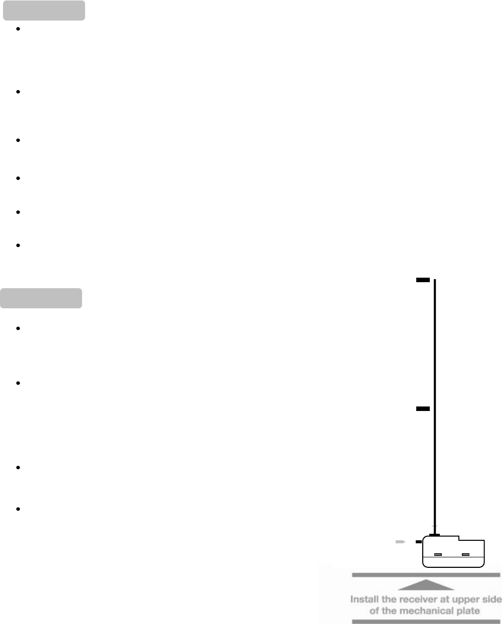
Caution receiver antenna instrallation
Never cut, lengthen or bind the antenna wire as the
wavelength for 2.4GHz is short and it is very sensitive to
the length of antenna wire.
Keep the antenna wire away from metal or carbon material.
In case the antenna is installed outside, it should be
as close to the receiver as possible. If the antenna wire
from receiver to holder is longer, their sensitivity becomes
less.
Do not put the antenna wire directly on the metal or carbon.
Do not put the antenna wire near electric conductors such
as metal or carbon it causes less sensibility due to
interference.
Especially, such as right illustration, antenna wire should
be installed more than 30mm away from the electric
conductor.
Also note that the middle part of the antenna wire should
not be close to the metal or carbon.
Important !
Important !
Receiver
PCB
0mm 200mm
Should not be close to the metal o
r
carbon
100mm
A
ntenna
t
7
BEFORE SETTING
Set up the model before driving.
To change the transmitter settings, always stop the engine first and disconnect the motor wire.
When each lever is operated, a beeping sound will be heard.
Pay attention to linkage to servos on R/C cars. If the servo function is forced to stop this may cause
excess current to build which will shorten servo life. Adjust with steering rate and steering ATV.
RIGHT AND LEFT TURN ADJUSTMENT FUNCTION
(
STEERING ATV
)
Hold the wheel to full lock right and operate the trim lever. Repeat this for full left lock.
( Steering ATV level 20~150 )
This function ensures that the steering linkage does not lock.
STEERING RATE LEVER FUNCTION
Push the set up button and operate the steering trim lever to adjust the maximum
rudder angle of the steering servo. This is to ensure optimum running of your model.
( ST RATE= 20~100 )
STEERING TRIM LEVER FUNCTION
Keep the steering wheel in the neutral position and adjust the trim lever in order to set
up desired neutral position on the servo. ( Moving direction 0~50 for L/R ) 4 continuous quick beeps
indicate the 50 incremental positions. 2 continuous quick beeps indicate default neutral position.
This function ensures that the steering linkage does not lock.
THROTTLE TRIM LEVER FUNCTION
When operating this lever without holding the trigger, you can adjust the neutral position or stop
position. ( Moving direction 0~50 for UP/DOWN ) 4 continuous quick beeps indicate the
50 incremental
p
ositions. 2 continuous
q
uick bee
p
s indicate the default neutral
p
osition.
** Each trim
p
osition is indicated with a bee
p
in
g
sound
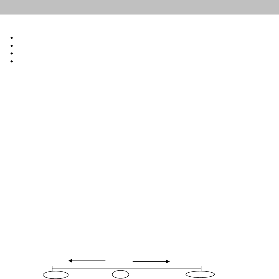
Left or backward Neutral Ri
g
ht or Forward
p
i
p
i
p
i
p
i
p
i
p
i
p
i
p
i
p
i
p
i
FORWARD AND REVERSE ANGLE ADJUSTMENT FUNCTION(Throttle ATV)
Hold the trigger to the forward position or reverse at maximum and then operate the throttle
trim lever can adjust the limits of the servo movement in each direction.
( Throttle ATV level 20~150 )
CHANGE SERVO ROTATION DIRECTION (Servo reverse)
You can adjust the steering reverse switch and the throttle reverse switch to
change the servo rotation direction.
RESTORE DEFAULT FUNCTION SETTING
Push the set up button for more than 2 seconds with keeping the wheel full lock
right, and the trigger full lock to forward, then release.
BATTERY ALARM
When the battery voltage < 6V the LED will turn off, when the input voltage < 9V the LED will flash
and buzzer beep. for 5S during operating. When this happens, please change the batteries to
new ones.
FUNCTION SETTING
8
9

IMPORTANT Electrical characteristics for 2.4GHz frequency
2.4GHz uses a very high frequency, the product will not be effected by motor noise.
However, the electrical signal characteristics are very different to lower frequencies.
The presence of metal parts or carbon between TX antenna and RX antenna, can weaken
the signal and cause interference. If RX antenna is covered by metal or carbon,
please change the position of the installation.
When racing, never switch on the TX in an area other than the drivers stand, to prevent
interference to other drivers.
2.4GHz signals are easily distorted by metal parts.
If the transmitter operation become slow at the track, please move
your driving position. Please also check that the receiver is correctly installed.
Any metal obstacle between driver and car may result in a loss of signal i.e. a metal crash
barrier on a racing circuit.
If you experience interference, stop the car, switch off the TX and then switch on again.
The transmitter will scan for a new band, which may improve the reception and reduce interference.
More than 3.5V is necessary to operate the receiver correctly.
When running an electric car, if low voltage occurs the receiver may reset itself.
If you are using 4 or 5 cell power battery for driving, installing an additional power source for
the receiver is highly recommended.
10
11
12

13
e
.
14
15