CDVI WIRELESS S P A DTRR1 RECEIVER DIGITAG-LR MOD. DTRR1434 User Manual IS RRDTML1
CDVI WIRELESS S.P.A. RECEIVER DIGITAG-LR MOD. DTRR1434 IS RRDTML1
User Manual
Introduction
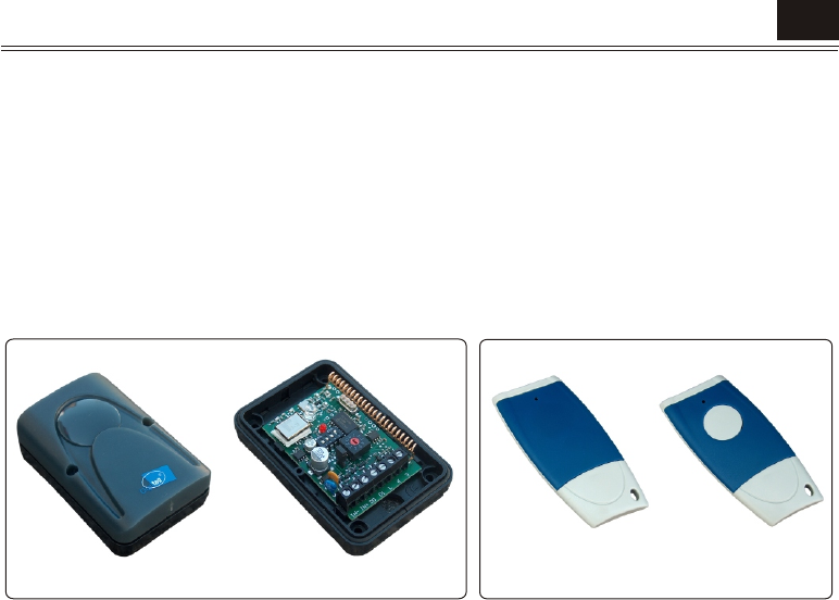
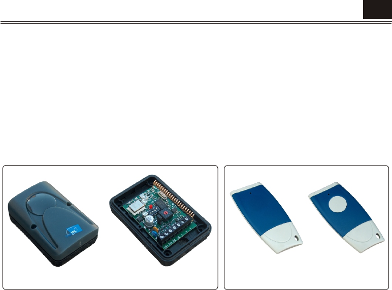
The DigiTag-LR Receiver is designed to be used with the DigiTag-LR range of active transmitters from the CDV
Group. Best performance from the transmitter and receiver will be gained when adhering to all the relevant
instructions. The DigiTag-LR receiver will read and decode the secure coded signal from the transmitter when in
the field range of the receiver, and convert this in to a format for access control units to validate. The DigiTag-LR
Receiver is equipped with a low / high gain selector and a range attenuator for further detection range reduction.
The exact range is dependant on environmental conditions, mounting proximity to metal objects and battery
condition of the transmitter. The DigiTag-LR receiver contains an internal antenna that must not be modified as it
is tuned for best performance. It must always be mounted upright and clear of metal obstacles or mountings.
The system fully complies with European Directives 73/23/EEC, 89/336/EEC, 99/05/EC, the FCC Part. 15
Regulation and Industry Canada RSS-210 Radio Standard Specification.
Digitag-LR Types
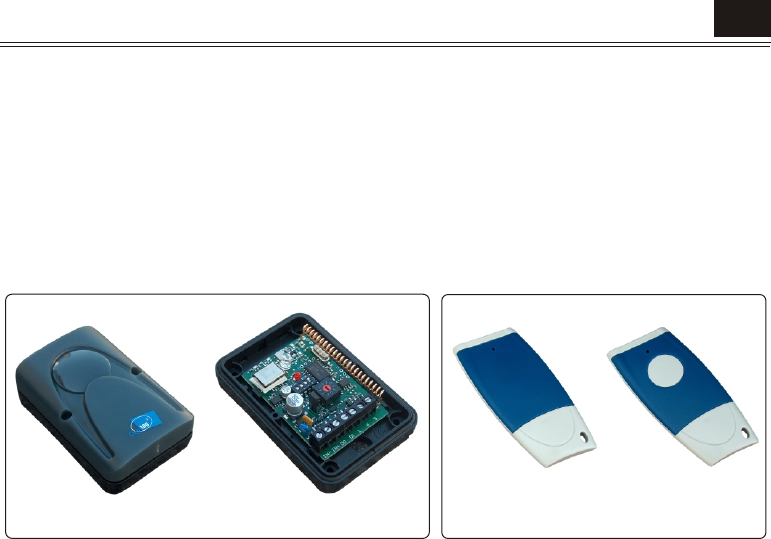
Digitag-LR Receiver ......................................DTRR1434
Digitag-LR Transmitter w/button ....................DTXT1434
Digitag-LR Transmitter ..................................DTXT0434
Technical Specification
Receiver
Operating frequency.....................................433,92 MHz
Operating voltage .........................................12-30 Vdc
Operating current..........................................40 mA
Range15M nominal .....................................(conditions dependant)
Output interface1..........................................Wiegand 26 Bit / Clock & Data ISO
Output interface 2.........................................CDV 1 wire control protocol
Transmitter buffer .........................................20
Tags in field...................................................20 max
Control 1.......................................................high / low gain
Control 2.......................................................10 point attenuator
LED...............................................................1 green and 1 red
Antenna ........................................................Internal helical
Sensitivity .....................................................-102dBm
Transmitter
Operating frequency .....................................433,92 MHz
Modulation ...................................................FSK
E.r.p ..............................................................5 µW
Supply...........................................................3V
Battery ..........................................................CR2032
DTXT1434
DTXT0434
USE AND INSTALLATION MANUAL
DTRR1434
EN
Pag. 2 Digitag-LR - Use and installation manual
Installation Procedure
The DigiTag-LR Receiver is designed to be mounted in proximity to the door or opening at a height of 1200 - 1400
mm. It is not recommended that the receiver is mounted over the door, but as a conventional access control
reader would be. Always mount the receiver in the upright position. The DigiTag-LR receiver has an internal
antenna that detects the DigiTag-LR range of active transmitters most efficiently at the front and the rear of the
unit. Avoid mounting the reader on or near large metal surfaces as this could cause poor reading performance,
erratic transmitter detection or non-linear operation. The receiver can not read active tags through metal objects
and will be impeded by large dense obstacles between it and the tag, so always think line-of-site for optimal
reading performance. Cable connections are by way of screw terminals on the bottom of the circuit board, and
we recommend the use of screened cable such as Beldon 9535 or an equivalent.
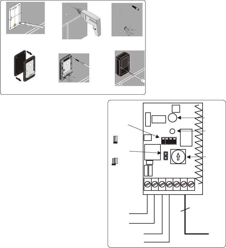
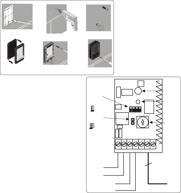
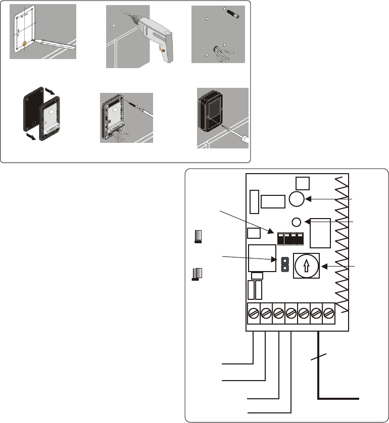
Fixing the enclosure
Fig. 2 Fig. 3 Fig. 4
Fig. 5 Fig. 6 Fig. 7
1 - Mark the location of the fixing
holes using the drilling template
supplied with the receiver ( Fig. 2 );
2 - Drill the fixing holes.( Fig. 3)
(Hole diam: 5mm) ;
3 - Locate the plugs ( Fig. 4 );
4 - Assemble the seal and the
receiver ( Fig. 5 );
5 - Mount the receiver with the
screws supplied ( Fig. 6 );
6 - Make the electrical connections
and the adjustments required ( see
next paragraph);
7 - After the adjustments, fit the
cover using the the screws supplied
( Fig. 7).
IN- IN+ DO D1 L 6 3
0V
10 - 30 Vdc
Data0
Data1
3
CDV-BUS
RED
Led
GREEN
Led
JP1
Rotary
Switch
ON 1 2 3 4
Dip-switch
JP1 = Closed
Max sensitivity
JP1 = Open
Min sensitivity
Connection terminals
The DigiTag-LR Receiver can be connected
directly to the CDV Group DG-502M access control
unit or to any access control system controller that
supports the Wiegand 26 Bit or Clock & Data ISO
format industry standard interfaces. A maximum
cable distance when using screened cable is
around 30 metres to a CDV Group DG502M access
control unit or 75M when using the industry
standard Wiegand or Clock & Data interface option.
Pag. 3
Digitag-LR - Use and installation manual
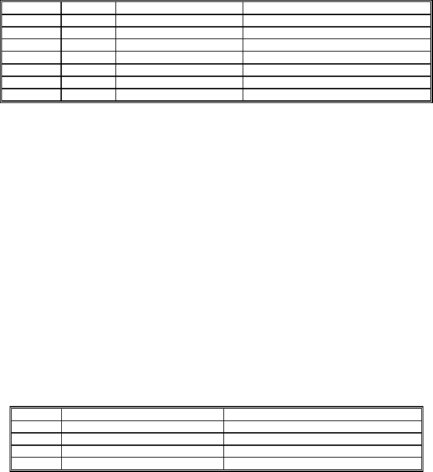
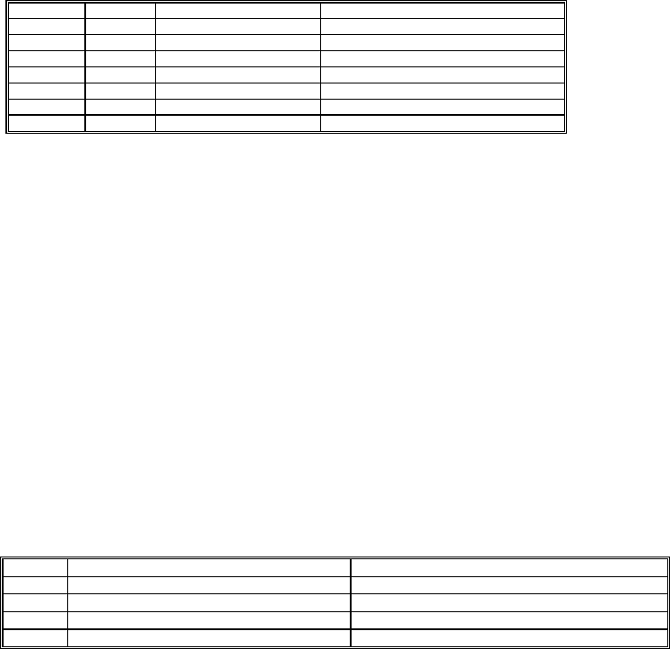
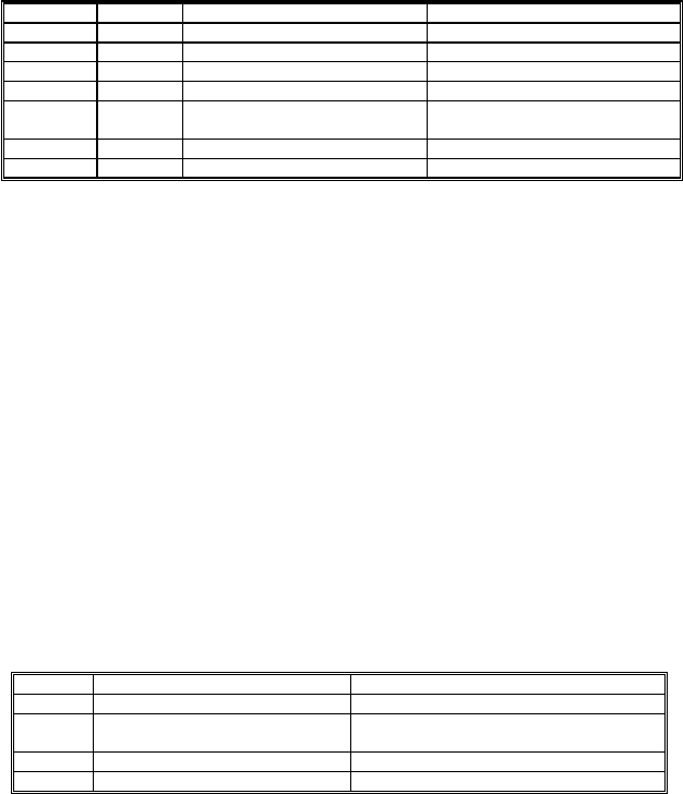
Terminal DG502M Type description
IN - 4 Input (cable screen *) - DC Voltage (cable screen*)
IN + 12 Input + DC, 12-30Volts
D0 n/c Output Wiegand 0 or Clock (Strobe)
D1 n/c Output Wiegand 1 or Data
L n/c Input Green LED control, active low
6 6 Input / Output CDV 1-wire control interface
3 3 Input Green LED, active high
* Cable screen should not be connected to any terminals inside the DigiTag-LR receiver but
enter the case where it must be trimmed short and insulated.
LED Indicators
The DigiTag-LR receiver has 2 LED lights. The red is always on and indicates that power is applied to the device
and it is ready to read and decode transmitters. The high efficiency bright green flashes briefly when a
transmitter's transmission is detected in the field. The green LED remains on if the connected access control
system validates the transmitted code. Whilst the green LED is illuminated the receiver will not read and decode
any more transmitter transmissions.
Range Adjustment
The maximum range of the receiver is dependant on environmental conditions, transmitter orientation and
transmitter battery life but should be approximately 15M in high gain mode and the attenuator control set to
position '0'. A small 2 pin jumper is present and if disconnected selects low gain mode. Additional the attenuator
control can be rotated to give further range reductions. The lowest range setting would therefore be with the
attenuator set to '9' and the low gain mode selected on the 2 pin jumper.
DIP Switch Settings
The DigiTag-LR receiver has options to select output interface type and various logical settings.
Switch ON OFF
1 Clock & Data interface Wiegand 26 Bit interface
2 Manual tag transmissions only Manual or automatic tag transmissions
3 Tag only read twice Tag always read
4 Pull up resistors connected Outputs open collector
Switch 1 : Selects the industry standard interface device type. It is recommended that this switch remains off
and utilise the Wiegand 26 Bit standard when connecting to third party access controls or to the CDV Group
brands Link.net & Centaur.
Switch 2 : When off allows both automatic and manual pressed transmissions to be read and decoded but when
set to on, will only read and decode manual user pressed transmissions.
Switch 3 : When set to off enables the tag to be read and decoded repeatedly whilst in the receivers detection
field.
When on, the tag is read and decoded only twice before ignoring it until it is removed from the receiver's detection
field for at least 10 seconds.
Switch 4 : When on, connects two 4K7 pull-up resistors to the outputs D0 and D1 to 5Volts. This switch should
be normally on but in some cases third party access control units require open-collector style outputs and in this
case switch 4 should be off.
Pag. 4 Digitag-LR - Use and installation manual
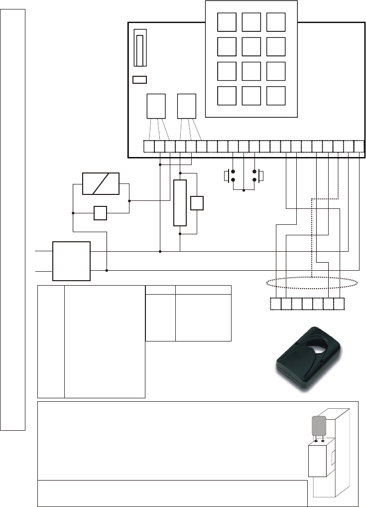
DigitagLR to DG-502UM
STAND-ALONE LONG RANGE ACCESS CONTROL
Screen
1 2 3
4 5 6
7 8 9
Þ 0 #
C R T R C T S S B M E 1 2 3 4 5 6 12 V 12
12 3
ST1
…
RL1 RL2
12V +
12V -
230V~
V1
MAGNET
V2
Strike
PB1 PB2
+
IN-
D0
L 6 3
D1
IN+
V
This device comes with a varistor. The varistor must be connected to the
strike terminals operated by the device.
If this product works with more strikes, each of them should have a
varistor.
* When connecting a DIGITAG-LR long range receiver to the DG-502UM
blease used Belden 9534 screened cable or equivalent. The screen is
connected at the DG-502UM in the spare V terminal but insulated inside
the DIGITAG LR case and never terminated
Relay 1 ( RL1 ) is active relay when connecting the Digitag LR receiver as
shown
WIRING DIAGRAM DG-502UM-DIGITAG-LR
B Push button 1
E Push button 2
M Common PB1 PB2
R N/C contact
C Common
T N/O contact
V1 Varistor RL1
V2 Varistor RL2
ST1 Reset jumper
S,S Trigger output
RL1 Door 1 relay output
RL2 Door 2 relay output
DG502 DIGITAG LR
12 IN+
V SCREEN *
4 IN-
66
33
Digitag-LR - Use and installation manual Pag. 5
MANUEL D’INSTALLATION ET UTILISATION FR
Introduction
Le récepteur DigiTag-LR est conçu pour être utilisé avec la gamme d'émetteurs DigiTag LR du Groupe CDV. Une
optimisation des performances de l'émetteur et du récepteur sera obtenue en suivant les instructions ci-
dessous. Le récepteur DigiTag LR lira et décodera le signal sécurisé du signal émis par l'émetteur dans le champ
couvert par le récepteur et le convertit dans un format pour les unités de contrôle d'accès.
Le récepteur DigiTag LR est muni d'un sélecteur de gain élevé et d'un réducteur de portée afin de réduire
davantage le rayon de détection. La portée exacte dépend de la configuration de l'environnement, des
conditions de montage du récepteur à proximité d'éléments métalliques et du niveau de la pile de l'émetteur. Le
récepteur DigiTag-LR est équipé d'une antenne interne qui ne doit pas faire l'objet de modification car elle a été
accordée pour une optimisation de sa performance. Il doit être toujours fixé verticalement et loin d'éventuels
obstacles ou supports métalliques.
Le système répond entièrement aux Directives Européennes 73/23/EEC, 89/336/EEC, 99/05/EC, ainsi qu’à la
régulation FCC Part 15 et la régulation RSS-210 de Industrie Canada.
Modéles Digitag-LR
Récepteur Digitag-LR ..................................DTRR1434
Emetteur avec bouton Digitag-LR .................DTXT1434
Emetteur Digitag-LR .....................................DTXT0434
Spécifications techniques
Récepteur
Fréquence ....................................................433,92 MHz
Alimentation de fonctionnement ...................12-30 Vdc
Consommation en fonctionnement...............40 mA
Portée initiale ...............................................15 (selon les conditions)
Sortie interface1 ...........................................Wiegand 26 Bit / Clock & Data ISO
Sortie interface 2 ..........................................Protocole de contrôle CDV 1 fil
Mémoire de l’émetteur..................................20
Emetteurs simultanés dans le champ...........20 maximum
Controle 1.....................................................Réglage de gain élevé et reduit
Controle 2.....................................................Réducteur de réception 10 positions
LED...............................................................1 verte and 1 rouge
Antenne ........................................................Interne en spirale
Sensibilité .....................................................-102dBm
Emetteur
Fréquence ....................................................433,92 MHz
Modulation ...................................................FSK
E.r.p ..............................................................5 µW
Alimentation..................................................3V
Batterie .........................................................CR2032 lithium
DTXT1434
DTXT0434
DTRR1434
Pag. 6 Digitag-LR - Use and installation manual
Digitag-LR - Use and installation manual
Procédure d'installation
Le récepteur DigiTag-LR est conçu pour être installé à proximité d'une porte ou d'une ouverture d'une
hauteur de 1200 à 1400mm. Il n'est pas recommandé d'installer le récepteur au dessus de la porte, mais
dans les mêmes configurations qu'un lecteur de contrôle d'accès habituel. Installez toujours le récepteur en
position verticale. Le récepteur DigiTag-LR est muni d'une antenne interne qui détecte le signal des
émetteurs de manière optimale à l'avant et à l'arrière de l'unité. Evitez d'installer le lecteur sur ou à proximité
d'une surface métallique pour éviter une déperdition de la performance de la lecture, une détection
irrégulière de l'émetteur ou un fonctionnement non linéaire. Le récepteur ne peut pas lire les badges actifs
aux travers d'objets métalliques et sera gêné par des obstacles compacts et nombreux pouvant être situés
entre le récepteur et le badge, aussi toujours raisonner avec un champ dégagé pour une performance
optimale de la lecture. Les câbles de connexion sont amenés aux bornes à visser dans la partie inférieure de
la carte électronique et nous recommandons l'utilisation de câbles blindés tel que Beldon 9535 ou
équivalent.
Fig. 2 Fig. 3 Fig. 4
Fig. 5 Fig. 6 Fig. 7
Fixation du boîtier
1- Marquez l'emplacement des trous
de fixation en utilisant le gabarit
fourni avec le récepteur (Fig.2) ;
2- Percez les trous de fixation (Fig 3)
(Diam du trou : 5mm) ;
3- Positionnez les chevilles (Fig 4) ;
4- Assemblez le joint et la base du
récepteur (Fig 5) ;
5- Fixez le récepteur avec les vis
fournies (Fig 6) ;
6- Effectuez les branchements
électriques et les réglages (voir
paragraphe suivant);
7- Après avoir effectué les réglages,
fixez le couvercle en utilisant les vis
fournies (Fig.7).
Bornes de connexion
Le récepteur DigiTag-LR peut être relié directement
à l'unité de contrôle d'accès DG-502M du Groupe
CDV ou à tout autre contrôleur de système de
contrôle d'accès qui autorise les interfaces
standard au format Wiegand 26bit ou Clock & Data
ISO. La distance maximale avec utilisation d'un
câble blindé est de 30m entre le récepteur et une
unité de contrôle d'accès DG502M du Groupe CDV
ou 75m entre le récepteur et une autre unité
utilisant les interfaces standard Wiegand ou Clock
& Data .
IN- IN+ DO D1 L 6 3
0V
10 - 30 Vdc
Data0
Data1
3
CDV-BUS
Led
ROUGE
Led
VERT
JP1
Réducteur
10 positions
ON 1 2 3 4
Dip-switch
JP1 = Fermé
Max sensibilité
JP1 = Ouvert
Min sensibilité
Pag. 7
Borne DG502M Type Description
IN- 4 Entrée (câble blindé) Vdc- (câble blindé)
IN+ 12 Entrée Vdc+ 12-30Volts
D0 n/c Sortie Wiegand 0 ou Clock (stroboscopique)
D1 n/c Sortie Wiegand 1 ou Data
L n/c Entrée Led verte de contrôle, alumée faible.
6 6 Input/Sortie Interface 1 fil CDV
3 3 Entrée Led verte, allumée brillante.
* Le blindage du câble ne doit être connecté à aucune borne à l'intérieur du récepteur DigiTag-LR
mais doit entrer à l'intérieur du coffret où il doit être coupé à ras et isolé
.
Indicateurs LED
Le récepteur DigiTag-LR est équipé de 2 leds lumineuses. La led rouge est toujours allumée et indique que le
systeme est alimenté correctement et que le récepteur est prêt à lire et décoder les émetteurs. La led verte
puissante clignote rapidement et brièvement quand le signal d'un émetteur est détecté dans le champ du
récepteur. La led verte reste allumée si le système de contrôle d'accès connecté valide le code reçu. Pendant
que la led verte est allumée, le récepteur ne lira et ne décodera plus aucun signal transmis par un émetteur.
Réglage de la portée
La portée maximale du récepteur dépend des conditions environnementales, de l'orientation de l'émetteur et de
l'état d'usure de la pile, mais doit être d'environ 15m en mode gain élevé avec le réducteur positionné sur « 0 ».
Un petit cavalier à 2 pin est présent et s'il est retiré, le mode gain réduit est sélectionné. Par ailleurs, le contrôleur
d'atténuation peut être tourné pour réduire d'avantage la portée. Le réglage de la portée la plus basse serait par
conséquent effectué en positionnant le contrôleur sur « 9 » et le mode de gain réduit sélectionné grâce aux
cavalier à 2 pin.
Réglages des dipswitch
Le récepteur DigiTag-LR est équipé de dipswitch permettant de sélectionner le type d'interface de sortie et les
différents réglages :
Switch ON OFF
1 Interface Clock & Data Wiegand 26 bit interface
2 Emissions badges manuelles uniquement Emissions badges manuelles ou automatiques
3 Badge lu 2 fois seulement Badge lu continuellement
4 Résistance de pull-up connectée Sortie en collecteur ouvert
Switch 1 : Il sélectionne l'interface standard. Il est recommandé de laisser ce switch en position OFF et d'utiliser
le standard Wiegand 26bit lors de la connexion d'un contrôle d'accès tiers ou du Groupe CDV parmi les marques
Link.net ou Centaur.
Switch 2 : En position OFF autorise indifféremment les émissions manuelles et automatiques à être lues et
décodées. En position ON, seules les émissions manuelles sont lues et décodées
Switch 3 : Ce switch réglé en position OFF permet que le badge soit lu et décodé de manière répétitive tant qu'il
se situe dans la zone de portée. En position ON, le badge est lu et décodé 2 fois seulement puis est ignoré
jusqu'à ce qu'il soit hors de la portée du récepteur durant un minimum de 10 secondes.
Switch 4 : En position ON, connectez deux résistances de pull-up 4K7 entre les sorties D0 et D1 au 5 volt. Ce
Switch devrait être normalement en position ON mais dans certains cas, des contrôles d'accès du marché
nécessitent une sortie en collecteur ouvert et dans ce cas, le switch 4 devrait être en posi tion OFF.
Pag. 8 Digitag-LR - Use and installation manual
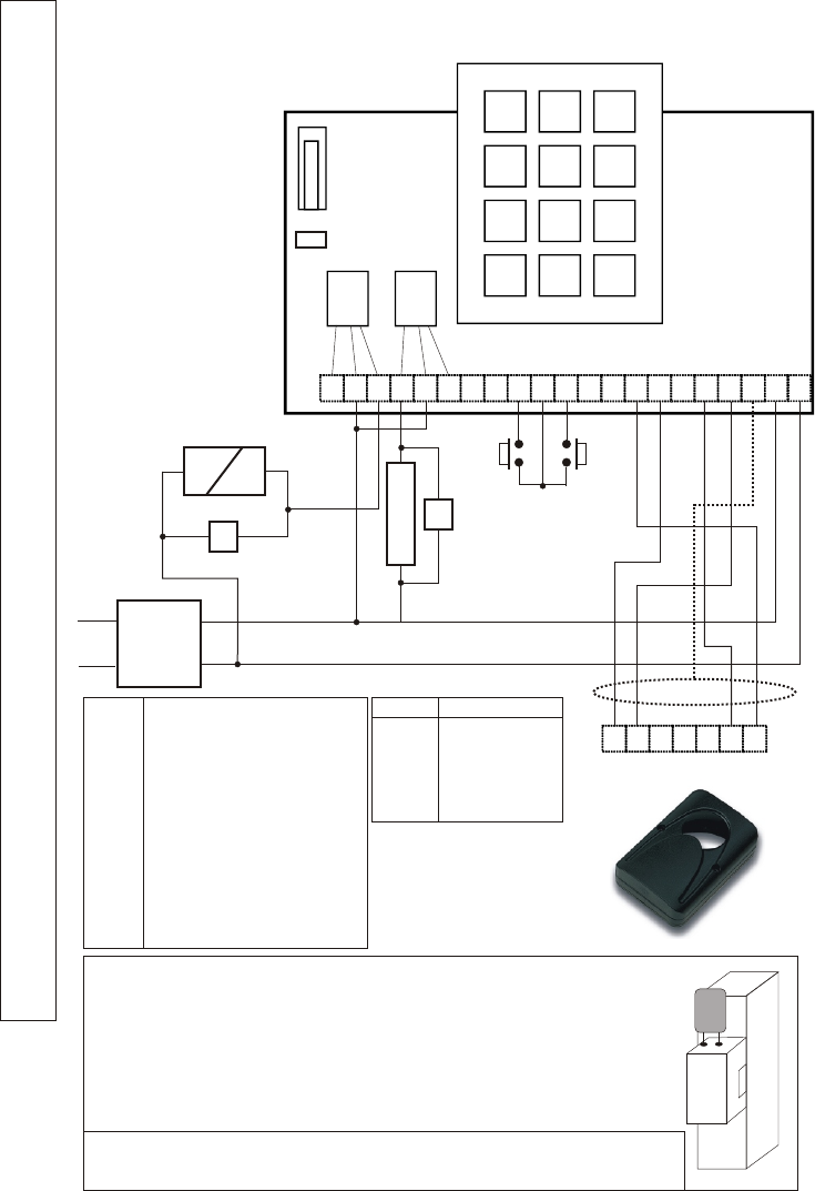
DigitagLR vers DG-502UM
CONTROLE D'ACCES AUTONOME LONGUE PORTEE
Blindage
1 2 3
4 5 6
7 8 9
Þ 0 #
C R T R C T S S B M E 1 2 3 4 5 6 12 V 12
12 3
ST1
…
RL1 RL2
12V +
12V -
230V~
V1
Ventouse
V2
Gâche
PB1 PB2
+
IN-
D0
L 6 3
D1
IN+
V
Le dispositif est équipé d'un varistor. Le Varistor doit être relié aux bornier
de la gâche commandée par le dispositif.
Si l'appareil commande plusieurs gâches, chacune doit être munie d'un
varistor.
* Lorsqu'un récepteur longue portée Digitag LR est connecté au DG-
502UM, nous vous recommandons d'utiliser du câble blindé type Belden
9534 ou équivalent. Le blindage est connecté à la DG-502UM par un
bornier séparé "V" qui est isloé à l'intérieur.
Le relais 1 est le relais activé le récepteur DIGITAG LR est établie.
SCHEMA DE CABLAGE DG-502UM - DIGITAG LR
B Bouton poussoir 1
E Bouton poussoir 2
M Commun PB1 PB2
R Contact NF
C Commun
T Contact NO
V1 Varistor RL1
V2 Varistor RL2
ST1 Jumper de réinitialisation
S,S Sortie gache
RL1 Sortie relais porte 1
RL2 Sortie relais porte 2
DG502 DIGITAG LR
12 IN+
V Blindage *
4 IN-
66
33
Digitag-LR - Use and installation manual Pag. 9
IS-RRDTML Rev. 1 on 17/05/2007
Introduzione
Il ricevitore Digitag-LR mod. DTRR1434 è concepito per l’uso con i trasmettitori Digitag-LR mod. DTXT0434 e
DTXT1434. Per il miglior utilizzo del prodotto si prega di leggere attentamente il presente manuale. Il ricevitore
Digitag-LR riceve, legge e decodifica il segnale radio codificato proveniente dai trasmettitori quando questi si
trovano entro la zona di rilevamento. Invia poi in uscita un segnale convertito nel formato adatto a dispositivi di
controllo accessi, per la successiva validazione. Il ricevitore è dotato di un selettore HIGH / LOW che varia il
guadagno e di un selettore che consente di regolare la sensibilità e di conseguenza la portata del trasmettitore.
Quest’ultima dipende dalle condizioni ambientali, dalla presenza o meno di oggetti metallici in prossimità
dell’unità ricevente e dallo stato della batteria del trasmettitore. Il ricevitore Digitag-LR è equipaggiato con una
speciale antenna elicoidale che non deve essere modificata poiché viene tarata per la massima sensibilità. Deve
essere installato lontano da superfici od oggetti metallici che ne possono modificare le caratteristiche
radioelettriche. Il sistema è conforme alle Direttive Europee 73/23/CEE, 89/336/CEE, 99/05/CE, alle Normative
FCC Part 15 e Industry Canada RSS-210.
Modelli Digitag-LR
Ricevitore Digitag-LR ....................................DTRR1434
Trasmettitore Digitag-LR con pulsante ..........DTXT1434
Trasmettitore Digitag-LR senza pulsante ......DTXT0434
Caratteristiche tecniche
Ricevitore
Frequenza portante ......................................433,92 MHz
Tensione di alimentazione ............................12-30 Vdc
Corrente........................................................40 mA
Portata nominale .........................................(dipende dalla condizioni)
Interfaccia di uscita 1....................................Wiegand 26 Bit / Clock & Data ISO
Interfaccia di uscita 2....................................CDV 1 wire control protocol
Capacità di memoria.....................................20
Max n° di tag nel campo...............................20
Controllo N°1 ................................................Guadagno High/Low
Controllo N° 2 ...............................................Selettore a 10 posizioni
LED...............................................................1 verde e 1 rosso
Antenna ........................................................Interna elicoidale
Sensitibilità ...................................................-102dBm
Trasmettitore
Frequenza portante ......................................433,92 MHz
Modulazione ................................................FSK
E.r.p ..............................................................5 µW
Alimentazione ...............................................3V
Batteria .........................................................CR2032
MANUALE D’USO ED INSTALLAZIONE IT
Pag. 10 Digitag-LR - Use and installation manual
DTXT1434
DTXT0434
DTRR1434
Procedura di installazione
Il ricevitore Digitag-LR è stato progettato per essere installato vicino ad una porta o ad una apertura ad un’altezza
dal terra di 1200 - 1400 mm. Si raccomanda di non installare il ricevitore sopra la porta come i rilevatori di
presenza standard. Montare sempre il ricevitore in posizione verticale con la morsettiera rivolta verso il basso.
L’apparecchiatura ha una antenna interna che rileva in modo più efficiente la presenza di trasmettitori Digitag-LR
dal lato frontale. Evitare di montare il ricevitore sopra o vicino a grandi superfici metalliche poiché ciò potrebbe
ridurre l’efficienza di ricezione, la rilevazione erronea di trasmettitori o un andamento non lineare del campo di
rilevamento. Il ricevitore non è in grado di leggere tag attivi attraverso oggetti metallici posti tra l’antenna di
ricezione ed il tag: per l’ottimizzazione delle prestazioni è bene quindi effettuare un’attenta analisi del sito prima
del fissaggio. Il ricevitore è dotato di morsetti a vite per le connessioni e si raccomanda l’uso di cavi come il
Beldon 9535 o equivalente.
Fasi di fissaggio
Fig. 2 Fig. 3 Fig. 4
Fig. 5 Fig. 6 Fig. 7
1 - Individuare la posizione dei fori
utilizzando la dima di foratura fornita
nella confezione ( Fig. 2 );
2 - Praticare i fori ( Fig. 3) ( diametro:
5mm) ;
3 - Inserire i tasselli ( Fig. 4 );
4 - Assemblare la guarnizione al
fondo ( Fig. 5 );
5 - Montare il ricevitore utilizzando le
viti fornite ( Fig. 6 );
6 - Fare le connessioni elettriche e
procedere con la regolazione ( ved.
prossimo paragrafo );
7 - Al termine della regolazione
fisare il coperchio e fissarlo alla base
con le viti fornite ( Fig. 7).
IN- IN+ DO D1 L 6 3
0V
10 - 30 Vdc
Data0
Data1
3
CDV-BUS
Led
ROSSO
Led
VERDE
JP1 Selettore
rotativo
ON 1 2 3 4
Dip-switch
JP1 = Chiuso
Sensibilità max
JP1 = Aperto
Sensibilità min.
Collegamenti
Il ricevitore DigiTag-LR può essere connesso
direttamente ad una unità di controllo accessi mod.
DG-502M del Gruppo CDV oppure a qualsiasi
sistema di controllo accessi che supporta il formato
Wiegand 26 bits o l’interfaccia standard Clock &
Data ISO.
La massima distanza a cui si può collegare il
ricevitore dall’unità di controllo DG502M è circa 30m
mentre si può arrivare a 75 m usando il protocollo
Wiegand o ISO Clock & Data.
Pag.11
Digitag-LR - Use and installation manual
Morsetto DG502M Tipo Descrizione
IN - 4 Ingresso (cavo schermato *) - Tensione DC (cavo schermato*)
IN + 12 Ingresso + DC, 12-30Volts
D0 n/c Uscita Wiegand 0 o Clock (Strobe)
D1 n/c Uscita Wiegand 1 o Data
L n/c Ingresso LED verde di Controllo, Attivo
basso
6 6 Ingresso / Uscita Interfaccia ad 1 filo CDV 1
3 3 Ingresso LED verde, attivo alto
* La schermatura del cavo non deve essere collegata ad alcun morsetto all’interno del
ricevitore DigiTag-LR ma deve essere tagliata ed isolata
LED
Il ricevitore Digitag-LR ha 2 led. Il led ROSSO è sempre acceso ed indica che il dispositivo è alimentato ed è
pronto a leggere i codici dei trasmettitori. Il led VERDE ad alta efficienza lampeggia brevementequando riceve il
segnale di un trasmettitore presente nella zona di rilevamento. Esso rimane acceso se il sistema di controllo
accessi dà il consenso al codice ricevuto. Per tutto il tempo in cui il led VERDE è acceso il ricevitore non può
ricevere ed abilitare altri trasmettitori
Regolazione della portata
La portata massima del ricevitore dipende dalle condizioni del sito, dall’orientazione del trasmettitore, dalla
carica della batteria ma dovrebbe essere circa di 15 m in modo “Alto guadagno” , con il jumper di controllo
posizionato in ‘0’. Il ponticello deve essere presente: se è disconnesso il modo selezionato è basso guadagno.
Ruotando il commutatore a 10 posizioni è possibile ottenere una regolazione più precisa della portata. La portata
minima si ottiene con l’attenuatore posizionato su '9' e con il jumper disconnesso.
Impostazione Dip-switch
Il ricevitore DigiTag-LR ha delle opzioni per impostare l’interfaccia di uscita ed altri parametri.
Dip ON OFF
1 Interfaccia Clock & Data Interfaccia Wiegand 26 Bit
2 Abilitata solo la trasmissione
manuale del tag
Abilitata trasmissione manuale ed
automatica del tag
3 Il tag viene letto solo 2 volte Lettura del tag continua
4 Resistenze di pull-up collegate Uscite in open-collector
Dip 1 : Seleziona il tipo di interfaccia d’uscita. Si raccomanda di posizionare a OFF ed utilizza lo standard
Wiegand 26 bit quando il ricevitore viene collegato a sistemi di controllo accessi di terze part oppure ai sistemi
Link.net o Centaur CDV Group.
Dip 2 : Quando è su OFF viene effettuata la lettura delle trasmissioni sia manuali sia automatiche provenienti dal
tag mentre quando è posizionato su ON viene letto solo il codice delle trasmissioni manuali del tag.
Dip 3 : Quando è posizionato su OFF legge e decodifica ripetutamente il tag presente all’interno del campo di
ricezione. Se posizionato su ON legge e decodifica solo 2 volte fino a che il tag viene rimosso dal campo di
ricezione e vi rimane per almeno 10 sec.
Dip 4 : In posizione ON le uscite D0 e D1 sono collegate a 2 resistenze di pull-up da 4K7 collegate a 5Volt.
Questo switch dovrebbe essere normalmente in ON ma, in alcuni casi, i sistemi di controllo accessi di terze parti
richiedono uscite open-collector e in questo caso il dip 4 va posizionato su OFF.
Pag. 12 Digitag-LR - Use and installation manual
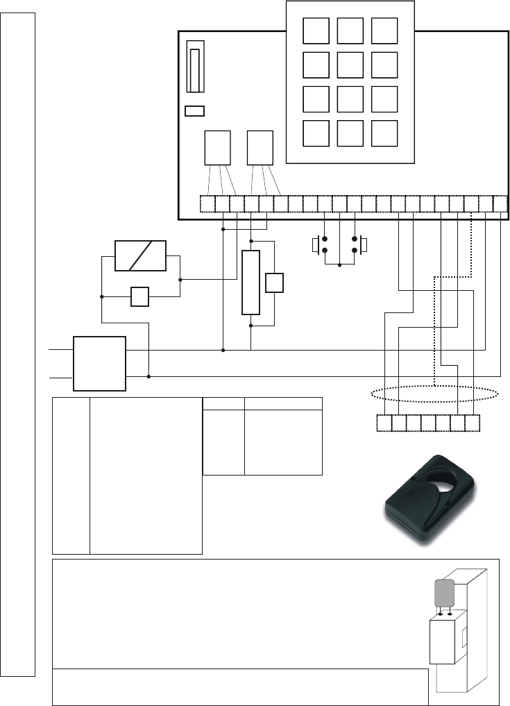
Da DigitagLR a DG-502UM
STAND-ALONE LONG RANGE ACCESS CONTROL
Schermo
1 2 3
4 5 6
7 8 9
Þ 0 #
C R T R C T S S B M E 1 2 3 4 5 6 12 V 12
12 3
ST1
…
RL1 RL2
12V +
12V -
230V~
V1
Magnete
V2
Elettroserratura
PB1 PB2
+
IN-
D0
L 6 3
D1
IN+
V
Questo dispositivo viene fornito con un varistore. Il varistore deve essere
connesso ai terminali dell’elettroserratura che viene utilizzata.
Se il prodotto comanda più elettroserrature, ciascuna di esse deve essere
dotata di varistore.
* Quando si collega un ricevitore lomg-range DIGITAG-LR al DG-502UM
usare un cavo schermato del tipo Belden 9534 o equivalente.
Lo schermo va collegato al terminale libero V del DG-502UM ma è isolato
internamente nel DIGITAG LR.
Il relè 1 ( RL1 ) è il relè attivo quando viene collegato il ricevitore
DIGITAG-LR come in figura.
SCHEMA DI COLLEGAMENTO DG-502UM-DIGITAG-LR
B Pulsante 1
E Pulsante 2
M Comune PB1 PB2
R Contatto NC
C Comune
T Contatto NA
V1 Varistore RL1
V2 Varistore RL2
ST1 Jumper di reset
S,S Uscita trigger
RL1 Uscita relè Porta 1
RL2 Uscita relè Porta 2
DG502 DIGITAG LR
12 IN+
V SCHERMO *
4 IN-
66
33
Digitag-LR - Use and installation manual Pag. 13
Pag. 14 Digitag-LR - Use and installation manual

Pag. 15
Digitag-LR - Use and installation manual
The guarantee period of this product is 24 months, beginning from the manufacturing date.
During this period, if the product does not work correctly, due to a defective component, it
will be repaired or substituted at the discretion of the producer.
The guarantee does not cover the plastic container integrity. After-sale service is supplied
at the manufacturer factory.
Guarantee
Garantie
La période de garantie de ce produit est de 24 mois, à compter de la date de fabrication.
Durant cette période, si le produit présentait un disfonctionnement en raison d'un
composant défectueux, il sera réparé ou échangé à la discrétion du fabricant. La garantie
ne couvre pas le coffret plastique.
Le service après-vente effectué sur le site du fabricant.
La garanzia è di 24 mesi dalla data di fabbricazione apposta all’interno. Durante tale
periodo, se l’apparecchiatura non funziona correttamente, a causa di un componente
difettoso, essa verrà riparata o sostituita a discrezione del fabbricante. La garanzia non
copre l’integrità del contenitore plastico.
La garanzia viene prestata presso la sede del fabbricante.
Garanzia
Manufactured by
ELPRO INNOTEK S.p.A.
ITALY
FCC ID: PWJDTRR1
"Changes or modifications not expressly
approved by the party responsible for
compliance could void the user's authority to
operate the equipment."
IC: 6863A-DTRR1

IS-RRDTML Rev. 4 on 22/04/2008