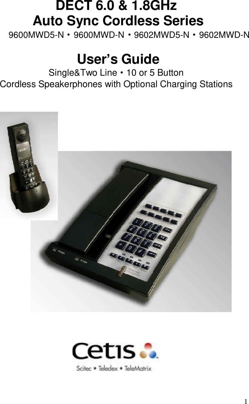
CETIS 9602MWD5-N DECT Telephone User Manual 9602 Auto Sync

CETIS,INC. DECT Telephone 9602 Auto Sync

Users Manual

  1  DECT 6.0 & 1.8GHz  Auto Sync Cordless Series   User’s Guide Single&Two Line·10 or 5 Button Cordless Speakerphones with Optional Charging Stations      9600MWD5-N    9600MWD-N    9602MWD5-N    9602MWD-N···
  2 DECT Base: 1.  Industrial grade construction,smooth plastic finish 2.  Speaker 3.  Programmable Store key 4.  Programmable Flash key (100ms to 1000ms timed line break) 5.  Line Cord receptacle (top end of phone) 6a. HSIA(High Speed Internet Access) receptacle incoming from wall (top end of phone) 6b. PassPort○R HSIA(High Speed Internet Access) receptacle outgoing to guest laptop 7.  Faceplate & Plastic Overlay display area (full-length,4-color printing possible) 8.  Guest Services Memory keys (10 or 5 keys) (store up to 15 digits maximum) 9.  Programmable Pause/Redial key (programmable for 1.0 to 5.0 second pause) 10a.Spdaker Volume key (up) (5-step control) 10b.Spdaker Volume key (down) (5-step control) 11. Handset Locate key with audio indication 12. Base Microphone 13. Speaker key with On/Off LED indication 14. Mute key with On/Off LED indication 15. TouchLiteTM Message Waiting key with 1-touch retrieval,bright red color,blinks when message waiting. 16a.Line 1 with LED indication 16b.Line 2 with LED indication 17. Electronic HOLD key (remote release) 18. Dial Pad(On-hook dialing possible with Memory keys and when Speaker key is activated) 19. Interchangeable handset cradle (provides for special accent colors to light ash or black telephones) 20. Handset Charging location (handset must be face down to charge) 21. In Use-Ringer indication light and Hold indication light 22. Charging Indication light 23. Desi strip display area
  3                                                              1        2                              3          4   5  6a                     24  25 26                                             6b                                                                                                                                                   7 27  28  29                                                                                                                                                 8 30                                                                                                                                                                                                                                                                                                  9 31                                                                                                                                                                                                                                                                                                  11   32a                                                                                                                                       10a 33                                                                                                                                                                                                                                                                                             10b  32b 34                   36  35   36                                                       22 23 20 19   21    18  17  16a 16b 15 14  13     12  Handset: 24. Cordless Handset –Handset can be synchronized with base with a few simple steps 25. Message Waiting Indicator,blinks when message is waiting 26. ADA Compliant Handset Speaker 27. Handset Faceplate & Plastic Overlay 28. Line Selector key – Line 2 On/Off with LED indication 29. Hold/Conf.Handset key,and remote release 30. Line Selector key – Line 1 On/Off with LED indication 31. Handset Dial Pad 32a.Handset Volume Up (5-Step) 32b.Handset Volume Down (5-Step) 33. Last Number Redial key 34. Flash key 35. Handset Microphone 36. Charging Location Contacts (Handset must be face down to charge)
  4                                                                          Telephone Underside:                                                                           37.  Base underside sticker information:                                                                                  Certification – FCC,CE,ETL,ROHS                                                                                  Version label                                                                                  Model name                                                                                  REN number                                                                                  Disposal label                                                                                  QC label                                                                                  Series number                                                                                  Warranty Void If Seal Broken label                                                                           38.  Message Waiting selector switch                                                                                  TYPE LR1 LR2                                                                           39.  Non-Slip rubber feet (4)                39                     37          38                                                                            Cordless Handset Charging Station:                                                                            40.  Message Waiting indication                       40                                                 41. Cordless Handset                                                                            42. Handset Pop-Off Cover for                                                                                   Battery compartment                                                                            43. Interchangeable Accent Piece,to                                                                                   match custom cradle color                                                                            44. Battery Charging & Synchronization                                                                                  programming indicator light                                                                      41  45. AC Power Plug-In.(back of stand)                                                                            46. Cordless Handset Charging Stand                                                                                  Handset will charge regardless of                                                                                   Whether it is placed with either front                                                                                  or back showing                                                                              Power Adaptor:                                                                             47. Phone Line from wall goes                                                                      42         into Line receptacles                                                                      43   48. Line to Phone from Adaptor                                                                       44                                                                                                                                            45                       47                                                                       46                                                                                                 48
  5 Cetis  GUIDE DECT6.0&1.8 GHz Two-Line Cordless Guestroom Telephone  Table of Contents: Features: Features & Controls Parts List Installation: Prepare Information Charging the battery Cleaning the battery contacts Battery safety Registering Handset to Base unit Operation: Placing a Call Receiving a Call Base Ringer Volume Base Speaker Volume Redial Key Hold Key Mute Key Handset Receive Volume Auto Dial Key Conference Servicing: Standard Safety Instruction Service  INCLUDED IN YOUR PACKAGE Cordless Handset  AC Adapter Base Unit  User Guide NiMH Battery  15-foot, 6-wire RJ-25 Line Cord 15-foot, 8-wire RJ-45 Cable Clear Plastic Overlay  The following are optional items possibly included:(Must be ordered separately)  Charging Stations & Handset with Handset Battery and Power Adaptor.    9602MWD-N Auto Sync SERIES USERS
  6 1. Prepare to install the battery into the cordless handset by Opening cover with small screwdriver.grip handset and depress Cover at hinged end.slide cover off,exposing battery compartment. 2. Slide battery plug into receptacle,matching up slot and opening  On receptacle. 3. Slide battery into battery compartment. 4. Press on back end of battery to snap into place. 5. Place hinged end of cover into slot,then press down and snap  into place. 6. Turn the telephone base so the back panel is facing you. Insert either end of the RJ-45 cable into the jack on the back of the telephone labeled LINE. 7. Insert the other end of the cable into the jack on the AC adapter labeled PHONE. 8. Insert one end of the RJ-25 line cord into the jack on the AC adapter labeled LINE. 9. Insert the other end of this line cord into a telephone jack. 10. Plug the AC adapter into an unswitched electrical outlet. 11. Once your telephone is connected, remove the plastic overlay and place the paper faceplate over the keys. Replace the plastic overlay by hooking the tabs on the overlay into the recessed slots located on both sides. The overlay is easiest to insert when the left or right side tabs are inserted first, and the middle of the overlay is slightly bowed to allow for insertion of the other tabs. 12. Place the cordless handset on the base unit.  CHARGING THE BATTERY The rechargeable battery must be fully charged before using the phone for the first time. It is recommended that that battery pack be charged for approximately 15 to 20 hours, without interruption, before use. To charge the battery, place the handset, keypad down, in the base unit. Make sure the CHARGE LED on the base lights. If the LED does not light: 1. Ensure that the AC adapter is plugged in. 2. Ensure that the AC adapter is not plugged into a switched electrical outlet. 3. Ensure that the handset charging contacts at the bottom of the handset are making good contact with the base unit’s charging contacts.  CLEANING THE BATTERY CONTACTS To maintain a good charge, it is important to clean all charging contacts on the handset and base unit. Use a pencil eraser or other contact cleaner. Do not use any liquids or solvents.  BATTERY SAFETY INSTRUCTIONS 1. Use only Cetis-approved battery replacements. 2. Dispose of used batteries according to local codes pertaining to NiMH batteries. 3. Do not dispose of batteries in fire, as they may explode 4. Charge the telephone's batteries only while in the telephone handset, and only by using the telephone base unit to charge. Do not attempt to remove the batteries and charge them in a separate charging unit. 5. Do not short-circuit the battery pack, as this may cause it to explode or catch fire.  HANDSET/BASE REGISTRATION PROCEDURE This procedure establishes an exclusive link between a specific handset and base, thereby allowing no other access to this PREPARING TO USE THE 9602MWD-N SERIES
  7 specific base. To accomplish this procedure, place the handset on the base in the charging position. This process occurs each time the handset is placed on the base in the charging cradle.  PLACING A CALL Using the handset: 1. Pick up the handset and select either line 1 or line 2. Listen for dial tone and dial the desired number. 2. After the call is complete, press the key for the selected line again to end the call. Using the speakerphone: 1. Press key for either line 1 or line 2, or press SPKR. 2. Listen for dial tone, and dial the desired number, or press an auto dial key to dial a preprogrammed number. 3. After the call is complete, press the SPKR key to end call.  RECEIVING A CALL An audible ring and flickering red LED indicate an incoming call. To answer the call using the handset while it is not on the base: 1. Pick up the handset. 2. Press the line key for the ringing line. The handset will go “off-hook” answering the ringing line. 3. To end the call, place the handset in the base unit cradle, or press the lit line key on the handset. To answer the call using the handset while it is resting on the base: 1. Pick up the handset from the base. The phone will automatically connect to the correct, ringing line. 2. To end the call, replace the handset in the base unit cradle, or press the lit line key on the handset. To answer the call using the speakerphone: 1. Press the line key for the ringing line. The speakerphone will go “off-hook”, answering the ringing line. 2. Or, press the SPKR key. The phone will automatically select the correct, ringing line. 3. To end the call, press the SPKR key again.  ADJUSTING THE RING VOLUME The up and down volume keys will adjust the ringer volume of the telephone. Additionally, an optional “courtesy” ring mode, wherein the ring volume begins at the lowest setting, then automatically rings louder with each successive ring during an incoming call. To select the courtesy ring mode, follow these steps: 1.Press the FLASH key; then a key on the dial pad from 1- 4, depending upon the desired ring tone,the phone will ring once to  provide a sample of the selected ring tone.  2.Assign ring tone to a line.When you have selected a suitable  ring tone,press the STORE key,then press number  ‘3’ on the dial pad to assign the ring tone to line 1,or press number  ‘4’ on the dial pad to assign the ring tone to line 2 To return to regular ring mode:  Press the FLASH key; then the 1 key; then the STORE key;  then the number on the keypad that corresponds to the line  for which you wish to change regular ring mode.  ADJUSTING SPEAKERPHONE VOLUME The speakerphone has five(5) levels. To adjust speakerphone volume, locate the volume up/down keys, located on the front surface of the phone below the keypad. With the speaker active, located on the front.   the 9602MWD-N series telephone has
  8 REDIAL dialed. Off-hook, press the REDIAL key to redial the last number.  USING THE HOLD KEY The HOLD key places the call on hold locally at the cordless telephone. 1. With a call active, press the red HOLD key on either the To remove a call from hold: 1. Press the line key of the call on hold. This will remove the call from hold, making the call active again. 2. The red line LED will return to steady illumination, indicating the line is active. To change phones after placing a call on hold: 1. Place the call on hold as above. 2. Pick up the call at another telephone that is on the same line. The telephone will activate the line and remove the hold at the original telephone.  TO MUTE THE SPEAKERPHONE 1. Press the MUTE key on the base unit. The red LED above the MUTE key will illuminate. The party on the other end will not be able to hear you when the MUTE LED is lit. 2. Press the MUTE key again to turn off the mute feature. The MUTE LED will go out.  ADJUSTING HANDSET RECEIVE VOLUME The handset has five(5) volume levels. To adjust the handset volume, locate the volume up/down keys, located on the handset, below the “#” key. Pressing the down key will decrease the volume level, while pressing the up key will increase it.  AUTO DIAL KEYS guest service (auto dial) keys, depending on the model you own. These keys can be programmed to automatically dial telephone numbers, or to activate telephone system features. To program the auto dial keys (programming can only be done from base unit): 1. With the phone “on hook” (inactive) and the faceplate removed, press the recessed STORE key (see diagram). 2. Enter the desired telephone number (up to 15 digits in length) to be stored. To enter a “pause” in the number string, press the REDIAL key as necessary. 3. Press the STORE key again. 4. Press the auto dial key where the number is to be stored. Programming is now completed for that auto dial key. To program additional keys, repeat this process.  CONFERENCE The “CONF” key allows for three-way conversations. Depending on the situation, you may initiate a conference call using one of these methods: User initiates two calls: 1. Place call to first party, then place them on hold by pressing the HOLD key. 2. Using the second line, place call to second party.then place them on hold by pressing the HOLD key. 3. Once those parties are on hold, activate the 3-way conference call by pressing HOLD key. User initiates one call: The 9602MWD-N series can automatically redial the last numberThe 9602MWD-N series has either five(5)or ten(10) programmable
  9 1. After receiving a call from first party, place them on hold as above. 2. Using the second line, place call to second party.then place  them on hold as above. 3. Once those parties are on hold, activate the 3-way conference call by pressing HOLD key. User includes two callers: 1. After receiving a call from first party, place them on hold as above. 2. After receiving call from second party, place them on hold as above. 3. Once those parties are on hold, activate the 3-way conference call by pressing HOLD key. To terminate a conference call, pressing a line key will maintain the connection with that line, while dropping the other line. To terminate the call entirely, press SPKR key to disconnect both parties.   REQUIREMENTS OF PART 68 - FCC RULES This device has been granted a registration number by the Federal Communications Commission, under Part 68 rules and regulations for direct connection to the telephone lines. In order to comply with these FCC rules, the following instructions must be carefully read and applicable portions followed completely: 1. Direct connection to the telephone lines may be made only through the standard modular cord furnished, to the utility installed jack. No connection may be made to party or coin phone lines. On the bottom of the phone is a label that contains among other information, the FCC Registration Number and the Ringer Equivalence number (REN) for this equipment. If requested this information must be provided to the telephone company. The USOC Jack for this equipment is RJ11C. 2. The telephone company, under certain circumstances, may temporarily discontinue and make changes in facilities and services which may affect the operation of the users' equipment: however, the user shall be given adequate notice in writing to allow the user to maintain uninterrupted service. 3. In certain circumstances, it may be necessary for the telephone company to request information from you concerning the equipment which you have connected to your telephone line. Upon request of the telephone company, provide the FCC registration number and the ringer equivalence number of the equipment which is connected to your line; this information will be found on the device. 4. If any of your telephone equipment is not operating properly, you should immediately remove it from the telephone line. It may cause harm to the telephone network. 5. If the telephone company notes a problem, they may temporarily discontinue service. When practical, they will notify you in advance disconnection. If advance notice is not feasible, the telephone company must; promptly notify you of such temporary discontinuance; afford the opportunity to correct the condition; inform you of your rights to bring a complaint to the FCC under their rules. 6. Repairs to the device may be made only by the manufacturer or an authorized service agency. This applies at any time during and after warranty. If unauthorized repair is performed, registration, connection to the telephone lines and remainder of warranty period all become null and void. 7. This equipment is hearing aid compatible. 8. This telephone must be connected behind a PBX.  REQUIREMENTS OF PART 15 - FCC RULES Statement according to FCC part 15.105: NOTE: This equipment has been tested and found to comply with the limits for a Class B digital device, pursuant to Part 15 of the FCC Rules. These limits are designed to provide reasonable protection against harmful interference in a residential installation. This equipment generates, uses and can radiate radio frequency energy and, if not installed and used in accordance with the instructions, may cause harmful interference to radio communications. However, there is no guarantee that interference will not occur in a particular installation. If this equipment does cause harmful interference to radio or television reception, which can be determined by turning the equipment off and on, the user is encouraged to try to correct the interference by one or more of the following measures: Reorient or relocate the receiving antenna; Increase the separation between the equipment and receiver; Connect the equipment into an outlet on a circuit different from that to which the receiver is connected. Consult the dealer or an experienced radio/TV technician for help. Statement according to FCC part 15.21: Modifications not expressly approved by this company could void the user’s authority to operate the equipment. RF Exposure (Handset) (DECT): This device and its antenna must not be co-located or operating in conjunction with any other antenna or transmitter. 9. If this product is equipped with a corded or cordless handset, it is hearing aid compatible.
10 RF Exposure mobile (Base) (DECT): The internal/external antennas used for this mobile transmitter must provide a separation distance of at least 20 cm from all persons and must not be co-located or operating in conjunction with any other antenna or transmitter. SAR: Tests for SAR are conducted using standard operating positions specified by the FCC with the UPCS handset transmitting at its highest certified power level in all tested frequency bands. Although the SAR is determined at the highest certified power level, the actual SAR level of the UPCS handset while operation can be well below the maximum value. In general, the closer you are to a wireless base station antenna, the lower the power output. Before a Handset model is available for sale to the public, it must be tested and certified to the FCC that it does not exceed the limit established by the government-adopted requirement for safe exposure. The tests are performed in positions and locations at the ear as required by the FCC for each model. While there may be differences between the SAR levels of various UPCS handsets and at various positions, they all meet the government requirement for safe exposure. Health and Safety Information FCC: Exposure to Radio Frequency (RF) Signals. Your wireless handset is a radio transmitter and receiver. It is designed and manufactured not to exceed the emission limits for exposure to radio frequency (RF) energy set by the Federal Communications Commission of the U.S. Government. These limits are part of comprehensive guidelines and establish permitted levels of RF energy for the general population. The guidelines are based on the safety standards previously set by both U.S. and international standards bodies: This EUT has been shown to be capable of compliance for localized specific absorption rate > (SAR) for uncontrolled environment/general population exposure limits specified in ANSI/IEEE> Std. C95.1-1992 and had been tested in accordance with the measurement procedures specified in FCC/OET Bulletin 65 Supplement C (2001) and IEEE Std. 1528-2003 December 2003).The standards include a substantial safety margin designed to assure the safety of all persons, regardless of age and health. The exposure standard for wireless UPCS handset employs a unit of measurement known as the Specific Absorption Rate, or SAR. The SAR limit set by the FCC and IC Canada is 1.6W/kg *. * In the U.S. and Canada, the SAR limit for mobile phones used by  INDUSTRY OF CANADA REQUIREMENTS NOTICE: The Industry Canada label identifies certified equipment. This certification means that the equipment meets certain telecommunications network protective operational and safety requirements as prescribed in the appropriate Terminal Equipment Technical Requirements documents. The department does not guarantee the equipment will operate to the users satisfaction. Before installing this equipment, users should ensure that it is permissible to be connected to the facilities of the local telecommunications company. The equipment must also be installed using an acceptable method of connection. The customer should be aware that compliance with the above conditions may not prevent degradation of service in some situations. Repairs to certified equipment should be coordinated by a representative designated by the supplier. Any repairs or alterations made by the user to this equipment, or equipment malfunctions, may give the telecommunications company cause to request the user to disconnect the equipment. Users should ensure for their own protection that the electrical ground connections of the power utility, telephone lines, and internal metallic water pipe systems, if present, are connected together. This precaution may be particularly important in rural areas. Caution: Users should not attempt to make such connections themselves, but should contact the appropriate electric inspection authority or electrician, as appropriate.  The Ringer Equivalence Number (REN) is an indication of the maximum number of devices allowed to be connected to a telephone interface. The termination of an interface may consist of any combination of devices subject only to the requirement that the sum of the RENs of all the devices not exceed five. / L'indice d'équivalence de la sonnerie (IES) sert à indiquer le nombre maximal de terminaux qui peuvent être raccordés à une interface téléphonique. La terminaison d'une interface peut consister en une combinaison quelconque de dispositifs, à la seule condition que la somme d'indices d'équivalence de la sonnerie de tous les dispositifs n'excède pas cinq.This device complies with Industry Canada licence-exempt RSS standard(s). Operation is subjectto the following two conditions: (1) this device may not cause interference, and(2) this device must accept any interference, including interference that may cause undesired operation of the device.Le présent appareil est conforme aux CNR d'Industrie Canada applicables aux appareils radio exempts de licence. L'exploitation est autorisée aux deux conditions suivantes :(1) l'appareil nedoit pas produire de brouillage, et(2) l'utilisateur de l'appareil doit accepter tout brouillage radioélectrique subi, même si le brouillage est susceptible d'en compromettre le fonctionnement.Under Industry Canada regulations, this radio transmitter may only operate using an antenna of a type and maximum (or lesser) gain approved for the transmitter by Industry Canada. To reduce potential radio interference to other users, the antenna type and its gain should be so chosen that the equivalent isotropically radiated power (e.i.r.p.) is not more than that necessary for successful communication.Conformément à la réglementation d'Industrie Canada, le présent émetteur radio peutfonctionner avec une antenne d'un type et d'un gain maximal (ou inférieur) approuvé pour l'émetteur par Industrie Canada. Dans le but de réduire les risques de brouillage radioélectrique à l'intention des autres utilisateurs, il faut choisir le type d'antenne et son gain de sorte que la puissance isotrope rayonnée équivalente (p.i.r.e.) ne dépasse pas l'intensité nécessaire à l'établissement d'une communication satisfaisante.This product meets the applicable Industry Canada technical specifications. Le présent matériel est conforme aux specifications techniques applicables d’Industrie Canada.
 11 SIMILAR SURFACE. THIS PRODUCT SHOULD NEVER BE PLACED NEAR OR OVER A RADIATOR OR HEAT REGISTER. THIS PRODUCT SHOULD NOT BE PLACED IN A BUILT-IN INSTALLATION UNLESS PROPER VENTILATION IS PROVIDED. 7. NEVER PUSH OBJECTS OF ANY KIND INTO THIS PRODUCT THROUGH CABINET SLOTS AS THEY MAY TOUCH DANGEROUS VOLTAGE POINTS OR SHORT OUT PARTS THAT COULD RESULT IN A RISK OF FIRE OR ELECTRIC SHOCK. NEVER SPILL LIQUID OF ANY KIND ON THE PRODUCT. 8. TO REDUCE THE RISK OF ELECTRIC SHOCK DO NOT DISASSEMBLE THIS PRODUCT. BUT TAKE IT TO A QUALIFIED SERVICE FACILITY IF SERVICE OR REPAIR WORK IS REQUIRED. OPENING OR REMOVING COVERS MAY EXPOSE YOU TO DANGEROUS VOLTAGES OR OTHER RISKS. INCORRECT REASSEMBLY CAN CAUSE ELECTRIC SHOCK WHEN THE APPLIANCE IS SUBSEQUENTLY USED. 9. UNPLUG THIS PRODUCT FROM THE WALL OUTLET AND REFER SERVICING TO QUALIFIED SERVICE PERSONNEL UNDER THE FOLLOWING CONDITIONS: - WHEN THE POWER SUPPLY CORD OR PLUG IS DAMAGED OR FRAYED. - IF LIQUID HAS BEEN SPILLED INTO THE PRODUCT. - IF THE PRODUCT HAS BEEN EXPOSED TO RAIN OR WATER. - IF THE PRODUCT DOES NOT OPERATE NORMALLY BY FOLLOWING THE OPERATING INSTRUCTIONS. ADJUST ONLY THOSE CONTROLS THAT ARE COVERED BY THE OPERATING INSTRUCTIONS, AS IMPROPER ADJUSTMENT OF OTHER CONTROLS MAY RESULT IN DAMAGE, AND MAY REQUIRE EXTENSIVE WORK BY A QUALIFIED TECHNICIAN TO RESTORE THE PRODUCT TO NORMAL OPERATION. - IF THE PRODUCT HAS BEEN DROPPED OR THE CABINET HAS BEEN DAMAGED. - IF THE PRODUCT EXHIBIT A DISTINCT CHANGE IN PERFORMANCE. 10. AVOID USING A TELEPHONE (OTHER THAN A CORDLESS TYPE) DURING AN ELECTRICAL STORM. THERE MAY BE A REMOTE RISK OF ELECTRIC SHOCK FROM LIGHTNING. 11. DO NOT USE THE TELEPHONE TO REPORT A GAS LEAK IN THE VICINITY OF THE LEAK. PLEASE SAVE THESE INSTRUCTIONS ALL RIGHTS RESERVED.  DECT6.0&1.8GHz Two-Line Cordless Guestroom Telephone CONTACTING Cetis Group Telephone Main: 1.719.638.8821 Toll-Free 1.800.462.9446 Fax: 1.719-638.8815 Internet www.Cetisgroup.com store.teledex.com Email sales@teledex.com Mailing Address 5025 Galley Road Colorado Spring, CO 80915 USA the public is 1.6 watts/kg (W/kg) averaged over one gram of tissue. The standard incorporates a substantial margin of safety to give additional protection for the public and to account for any variations in.   IMPORTANT SAFETY INSTRUCTIONS WHEN USING YOUR TELEPHONE EQUIPMENT, BASIC SAFETY PRECAUTIONS SHOULD ALWAYS BE FOLLOWED TO REDUCE THE RISK OF FIRE, ELECTRIC SHOCK AND INJURY TO PERSONS, INCLUDING THE FOLLOWING: 1. READ AND UNDERSTAND ALL INSTRUCTIONS. 2. FOLLOW ALL WARNINGS AND INSTRUCTIONS MARKED ON THE PRODUCT. 3. UNPLUG THE PRODUCT FROM THE WALL OUTLET BEFORE CLEANING. DO NOT USE LIQUID CLEANER OR AEROSOL CLEANERS. USE A DAMP CLOTH FOR CLEANING. 4. DO NOT USE THIS PRODUCT NEAR WATER, FOR EXAMPLE, NEAR A BATHTUB, WASH BOWL, KITCHEN SINK OR LAUNDRY TUB, IN A WET BASEMENT, OR NEAR A SWIMMING POOL. 5. DO NOT PLACE THIS PRODUCT ON AN UNSTABLE CART, STAND OR TABLE. THE PRODUCT MAY FALL, CAUSING SERIOUS DAMAGE TO THE PRODUCT. 6. SLOTS AND OPENINGS IN THE CABINET AND THE BACK OF BOTTOM ARE PROVIDED FOR VENTILATION, TO PROTECT IT FROM OVERHEATING. THESE OPENINGS MUST NOT BE BLOCKED OR COVERED. THE OPENINGS SHOULD NEVER BE BLOCKED BY PLACING THE PRODUCT ON THE BED, SOFA, RUG OR ANY OTHER 9602MWD-N SERIES DIAGRAM9602MWD-N SERIES USERS GUIDE

Navigation menu