5.User's manual
EXA100
Wireless AP Router
User Manual
Version A1.0, November 29, 2012

1
Preface
This manual provides information related to the installation and operation of
this device. The individual reading this manual is presumed to have a basic
understanding of telecommunications terminology and concepts.
Important Safety Instructions
With reference to unpacking, installation, use, and maintenance of your
electronic device, the following basic guidelines are recommended:
Do not use or install this product near water, to avoid fire or shock hazard.
For example, near a bathtub, kitchen sink or laundry tub, or near a
swimming pool. Also, do not expose the equipment to rain or damp areas
(e.g. a wet basement).
Do not connect the power supply cord on elevated surfaces. Allow it to lie
freely. There should be no obstructions in its path and no heavy items
should be placed on the cord. In addition, do not walk on, step on, or
mistreat the cord.
Use only the power cord and adapter that are shipped with this device.
This product is intended to be supplied by a UL Listed Power Supply with
marked with "L.P.S.", or "Limited Power Source", and output rated 12 Vdc,
minimum 1.0A.
To safeguard the equipment against overheating, make sure that all
openings in the unit that offer exposure to air are not blocked.
Avoid using a telephone (other than a cordless type) during an electrical
storm. There may be a remote risk of electric shock from lightening. Also,
do not use the telephone to report a gas leak in the vicinity of the leak.
Never install telephone wiring during stormy weather conditions.
The equipment is to be connected only to PoE networks without routing to
the outside plant.
Following instruction or similar in the manual wiring method should comply
article 725 and article 300 in national electrical code for class 2 circuit and
wiring in duct.
All the installation should performed by qualified personnel.
CAUTION:
To reduce the risk of fire, use only No. 26 AWG or larger
telecommunication line cord.
Always disconnect all telephone lines from the wall outlet before
servicing or disassembling this equipment.
WARNING
Disconnect the power line from the device before servicing.
Power supply specifications are clearly stated in Appendix B –
Specifications

2
Copyright
Copyright© 2012 Cetis Corporation. All rights reserved. The information
contained herein is proprietary to Cetis Corporation. No part of this
document may be translated, transcribed, reproduced, in any form, or by
any means without the prior written consent of Cetis Corporation.
This program is free software: you can redistribute it and/or modify it under
the terms of the GNU General Public License as published by the Free
Software Foundation, either version 3 of the License, or (at your option) any
later version.
This program is distributed in the hope that it will be useful, but WITHOUT
ANY WARRANTY; without even the implied warranty of MERCHANTABILITY
or FITNESS FOR A PARTICULAR PURPOSE. See the GNU General Public
License for more details.
You should have received a copy of the GNU General Public License
along with this program. If not, see http://www.gnu.org/licenses/
NOTE: This document is subject to change without notice.
Protect Our Environment
Thissymbolindicatesthatwhentheequipmenthasreachedtheendof
itsusefullife,itmustbetakentoarecyclingcentreandprocessed
separatefromdomesticwaste.
The cardboard box, the plastic contained in the packaging, and the parts
that make up this router can be recycled in accordance with regionally
established regulations. Never dispose of this electronic equipment along
with your household waste; you may be subject to penalties or sanctions
under the law. Instead, please be responsible and ask for disposal
instructions from your local government.
3
Table of Contents
Chapter1Introduction .................................................................................................... 5
1.1Features ................................................................................................................. 5
1.2Application............................................................................................................. 6
Chapter2Installation ...................................................................................................... 7
Chapter3WebUserInterface......................................................................................... 9
3.1DefaultSettings ..................................................................................................... 9
3.2IPConfiguration..................................................................................................... 9
3.3LoginProcedure................................................................................................... 11
Chapter4DeviceInformation ....................................................................................... 14
4.1Statistics............................................................................................................... 15
Chapter5WirelessSetting ........................................................................................... 16
5.1Basic.................................................................................................................... 16
5.2Advanced ............................................................................................................ 19
5.3Security ............................................................................................................... 21
5.4WDS .................................................................................................................... 23
5.5WPS..................................................................................................................... 26
5.6StationList .......................................................................................................... 28
5.7APWirelessStatistics......................................................................................... 29
Chapter6Management‐ConfigurationBackup........................................................... 30
6.1ManagementIP ................................................................................................... 30
6.2LEDControl .......................................................................................................... 31
6.3SNMPAgent......................................................................................................... 32
6.4TR‐069Client ....................................................................................................... 33
6.5UpdateSoftware.................................................................................................. 35
4
6.6Reboot ................................................................................................................. 37
6.7Configuration....................................................................................................... 38
6.7.1BackupSettings....................................................................................... 38
6.7.2UpdateSettings....................................................................................... 38
6.7.3RestoreDefault ....................................................................................... 39
AppendixA‐PinAssignments ....................................................................................... 40
AppendixB–Specifications........................................................................................... 41
AppendixC–ParameterRules ....................................................................................... 43
5
Chapter 1 Introduction
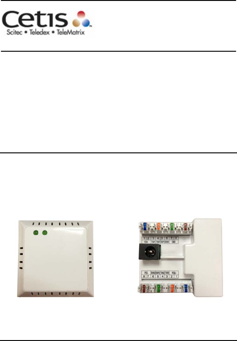
The EXA100 is a Wi-Fi AP module which can be inserted into
wall-mounted customized housing. The EXA100 is an 802.11n
(300Mbps) Wireless AP and is backward compatible with existing
802.11b (11Mbps) and 11g (54Mbps) equipment.
The EXA100 is customized for Hotel environment applications. It
is integrated to be power supplied by DC-Jack or punch
connector from Power over Ethernet Device and ADSL Router
(EXP100). Hence it can provide several kinds of application
methods to combine the wireless easily. It also provides state of
the art security features such as 64/128 bit WEP encryption and
WPA/WPA2 encryption, Firewall, and VPN pass through.
1.1 Features
● Wireless 802.11n access point – up to 300Mbps
● 2 LAN ports (punch by IDC connector)
● Browser based interface for configuration and management:
OS independent and easy to use
● Support CLI command to access Wireless AP
● Full wireless security – WEP, WPA, WPA2
● Power Supply for 3 options (DC-Jack / ADSL power in / PSE power in )
6
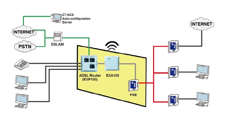
1.2 Application
The following diagrams depict typical applications of the EXA100.
7
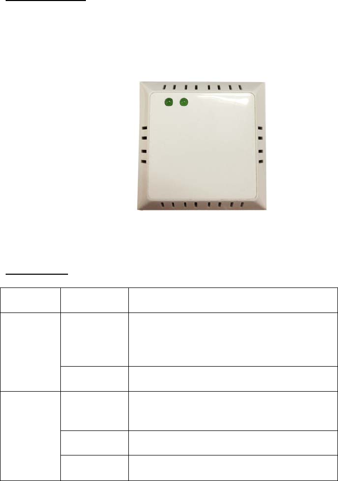
Chapter 2 Installation
FRONT PANEL
The figure below shows the front panel of the device.
LED Status
LED Status Descriptions
Solid OFF System is power off or system status
is abnormal or disabling ‘LED ON’ in
web UI.
Power
Solid ON System is operational
Solid OFF Wi-Fi is disabled or disabling ‘LED ON’
in web UI.
Solid ON Wi-Fi is operational
Wireless
Link
Flashing Data transmission through Wi-Fi
8
REAR PANEL
The figure below shows the rear panel of the device.
Caution 1: If the device fails to power up, or it malfunctions, first verify that
the power cords are connected securely and then power it on
again. If the problem persists, contact technical support.
Caution 2: Before servicing or disassembling this equipment, disconnect all
power cords and telephone lines from their outlets.
Reset Button
Restore the default parameters of the device by pressing the Reset button
for 5 to 10 seconds.

9
Chapter 3 Web User Interface
This section describes how to access the device via the web user
interface (WUI) using an Internet browser such as Internet Explorer
(version 5.0 and later).
3.1 Default Settings
The factory default settings of this device are summarized below.
LAN IP address: 192.168.1.254
LAN subnet mask: 255.255.255.0
Administrative access (username: root , password: 12345 )
User access (username: user, password: user)
Remote (WAN) access (username: support, password: support)
Technical Note
During power on, the device initializes all settings to default values. It will
then read the configuration profile from the permanent storage section of
flash memory. The default attributes are overwritten when identical
attributes with different values are configured. The configuration profile in
permanent storage can be created via the web user interface or telnet user
interface, or other management protocols. The factory default configuration
can be restored either by pushing the reset button for more than five
seconds until the power indicates LED blinking or by clicking the Restore
Default Configuration option in the Restore Settings screen.
3.2 IP Configuration
STATIC IP MODE
In static IP mode, you assign IP settings to your PC manually.
Follow these steps to configure your PC IP address to use subnet
192.168.1.x.
NOTE: The following procedure assumes you are running Windows XP.
However, the general steps involved are similar for most
operating systems (OS). Check your OS support documentation
for further details.
10
STEP 1: From the Network Connections window, open Local Area
Connection (You may also access this screen by double-clicking
the Local Area Connection icon on your taskbar). Click the
Properties button.
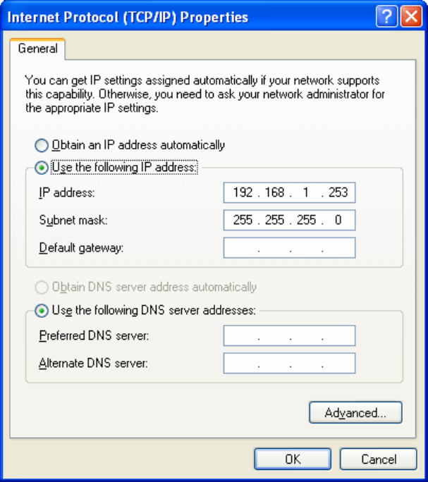
STEP 2: Select Internet Protocol (TCP/IP) and click the Properties button.
STEP 3: Change the IP address to the 192.168.1.x (1<x<255) subnet with
subnet mask of 255.255.255.0. The screen should now display as
shown below.
STEP 4: Click OK to submit these settings.

11
3.3 Login Procedure
Perform the following steps to login to the web user interface.
NOTE: The default settings can be found in 3.1 Default Settings.
STEP 1: Start the Internet browser and enter the default IP address for
the device in the Web address field. For example, if the default IP
address is 192.168.1.254, type http://192.168.1.254.
NOTE: For local administration (i.e. LAN access), the PC running the
browser must be attached to the Ethernet, and not necessarily to
the device.
For remote access (i.e. WAN), use the IP address shown on the
12
Chapter 4 Device Information screen and login with remote
username and password.
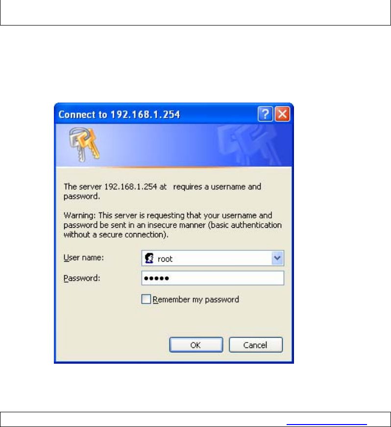
STEP 2: A dialog box will appear, such as the one below. Enter the default
username and password, as defined in section 3.1 Default
Settings.
Click OK to continue.
NOTE: The login password can be changed later (see 8.6.1 Passwords).
13
STEP 3: After successfully logging in for the first time, you will reach this
screen.
14
Chapter 4 Device Information
The web user interface window is divided into two frames, the main menu
(at left) and the display screen (on the right). The main menu has several
options and selecting each of these options opens a submenu with more
selections.
NOTE: The menu items shown are based upon the configured
connection(s) and user account privileges. For example, if NAT
and Firewall are enabled, the main menu will display the NAT and
Security submenus. If either is disabled, their corresponding
menu(s) will also be disabled.
Device Info is the first selection on the main menu so it will be discussed
first. Subsequent chapters will introduce the other main menu options in
sequence.
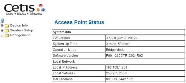
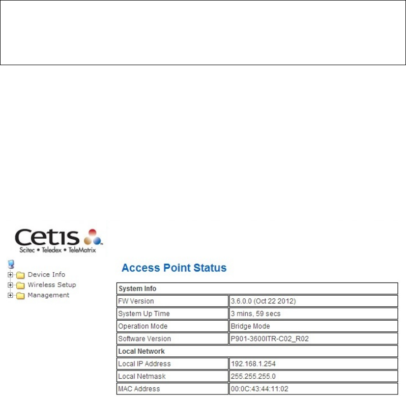
The Access Point Status screen displays at startup.
This screen shows software, IP settings and other related information.
15
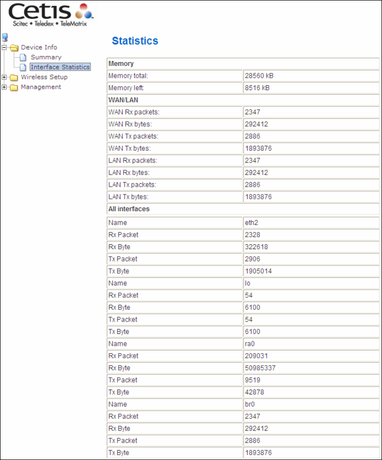
4.1 Statistics
Select Interface Statistics from the Device Info submenu to display
the following.
16
Chapter 5 Wireless Setting
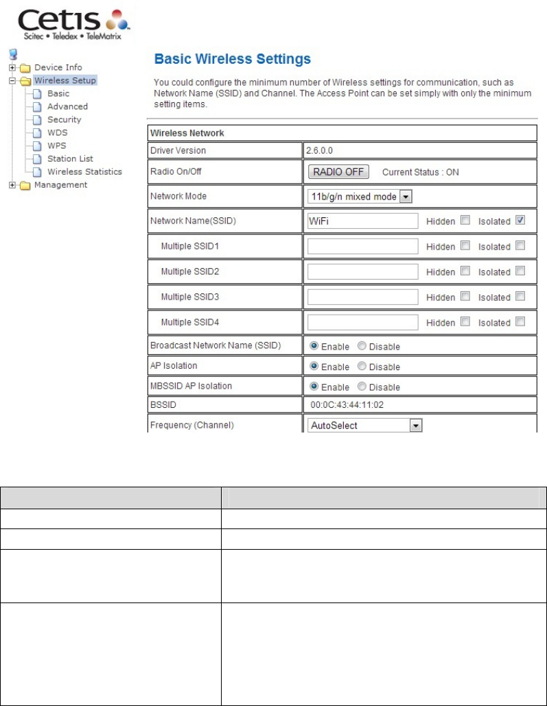
5.1 Basic
You can configure the minimum number of wireless settings for
communication, such as network name (SSID) and channel.
Wireless Network
Field Description
Driver Version Displays the version of the driver.
Radio On/Off: Enable or disable the wireless LAN.
Network Mode:
There are 5 modes: 11b only, 11g only,11n
only,11b/g mixed mode, and 11b/g/n mixed
mode.
Network Name (SSID):
The service set identification (SSID) is a
unique name to identify the router in the
wireless LAN. Wireless stations associating
to the router must have the same SSID.
Input a descriptive name. Its length is up to
32 characters.
17
Multiple SSID 1/2/3/4: This router supports multiple SSIDs called
Guest SSIDs or Virtual Access Points.
Broadcast Network Name
(SSID):
Select Enable to allow the SSID broadcast
on the network, so that the STA can find it.
Otherwise, the STA cannot find it.
AP Isolation:
Enable or disable AP Isolation. When many
clients connect to the same access point,
they can access each other. If you want to
disable the access between clients which
connect the same access point, you can
enable this function.
MBSSID AP Isolation: Enable or disable MBSSID AP Isolation.
BSSID:
Basic Service Set Identifier. This is the
assigned MAC address of the station in the
access point. This unique identifier is in Hex
format and can only be edited when Multi
BSSID is enabled in the previous screen.
Frequency (Channel):
A channel is the radio frequency used by the
wireless device. Channels available depend
on your geographical area. You may have a
choice of channels (for your region) and you
should use a different channel from an
adjacent AP to reduce the interference. The
Interference and degrading performance
occurs when radio signals from different APs
overlap.
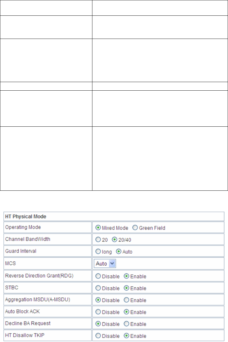
HT Physical Mode

18
Field Description
Operating Mode Two modes: Mixed Mode and Green Field
Default is Mixed Mode.
Channel BandWidth Set the channel bandwidth of wireless radio
20MHz and 20/40 MHz
Default is 20/40 MHz
Guard Interval Guard Interval is used to avoid that distinct
transmissions do not affect with one
another.
With Long Guard and Auto.
Default is Auto.
MCS Modulation and Coding Scheme
Range From 1 to 15, 32 and Auto
Default is Auto.
Reverse Direction
Grant(RDG) Enable or disable Reverse Direction
Grant(RDG). Default is enable.
STBC Enable or disable STBC. Default is enable.
Aggregation MSDU(A-
MSDU) Enable or disable Aggregation MSDU(A-
MSDU). Default is disable.
Auto Block ACK Enable or disable Auto Block ACK
Default is enable.
Decline BA Request Enable or disable Decline BA Request
Default is disable.
HT Disallow TKIP Enable or disable HT Disallow TKIP.
Default is enable.
Other
Field Description
HT TxStream Stream numbers transmits.
HT RxStream Stream numbers receives.
19
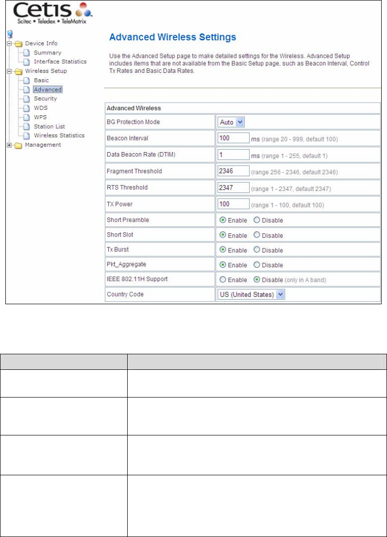
5.2 Advanced
Use this page to make detailed settings for the AP. Advanced Wireless
Settings page includes items that are not available in the Basic Wireless
Settings page, such as basic data rates, beacon interval, and data beacon
rate.
Advanced Wireless
Field Description
BG Protection Mode:
It provides 3 options, including Auto, On, and Off.
The default BG protection mode is Auto.
Beacon Interval:
The interval time range is between 20ms and
999ms for each beacon transmission. The default
value is 100ms.
Date Beacon Rate
(DTM):
The DTM range is between 1ms and 255 ms. The
default value is 1ms.
Fragment Threshold:
This is the maximum data fragment size (between
256 bytes and 2346 bytes) that can be sent in the
wireless network before the router fragments the
packet into smaller data frames. The default value
is 2346.
20
RTS Threshold: Request to send (RTS) is designed to prevent
collisions due to hidden nodes.
An RTS defines the biggest size data frame you
can send before an RTS handshake is invoked.
The RTS threshold value is between 1 and 2347.
The default value is 2347.
If the RTS threshold value is greater than the
fragment threshold value, the RTS handshake
does not occur. Because the data frames are
fragmented before they reach the RTS size.
Tx Power: The Tx Power range is between 1 and 100. The
default value is 100.
Short Preamble: Select Disable or Enable.
Short Slot: Select Disable or Enable.
Tx Burst: Select Disable or Enable.
Pkt_Aggregate: Select Disable or Enable.
IEEE802.1 H Support Select Disable or Enable.
Country Code:
Select the region which you are in. It provides six
regions in the drop-down list.
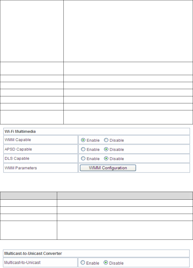
Wi-Fi Multimedia
Field Description
WMM Capable: Enable or disable WMM.
APSD Capable: Enable or disable APSD.
DLS Capable Select Disable or Enable.
WMM Parameters:
Click the WMM Configuration button to pop up the
WMM Parameters of Access Point page. You can
configure WMM parameters on the page.
Multicast-to-Unicast Converter: Enable or disable Multicast-to-Unicast
Converter.
After completing the settings above, click Apply to save the settings and
make the new configuration take effect. Click Cancel to close without
saving.
21
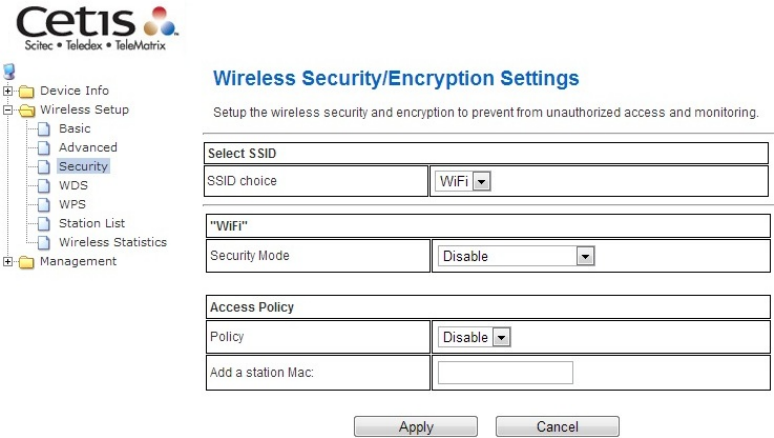
5.3 Security
Choose Wireless Settings>Security and the following page will be
displayed. It allows you to modify the settings to prevent unauthorized
accesses.
Select SSID
SSID choice: Select SSID from the drop-down list.
“default”
Security Mode: There are 11 options, including Disable, OPEN, SHARED,
WEPAUTO, WPA, WPA-PSK, WPA2, WPA2-PSK, WPAPSKWPA2PSK,
WPA1WPA2, and 802.1X.
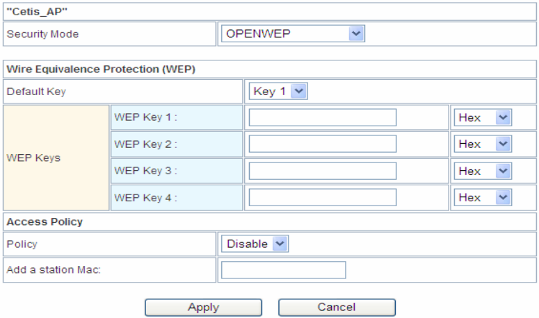
[EXAMPLE]
Take Open WEP for example. Select Open WEP from the Security Mode
drop down-list. The following page will be displayed.
22
Cetis AP
Security Mode:
There are 11 options, including Disable, OPEN, SHARED, WEPAUTO,
WPA, WPA-PSK, WPA2, WPA2-PSK, WPAPSKWPA2PSK, WPA1WPA2,
and 802.1X.
Wire Equivalence Protection (WEP)
WEP Key (1-4): Input the key to encrypt wireless data. To allow encrypted
data transmission, the WEP Encryption Key values on all wireless stations
must be the same as the router. There are four keys for your selection. The
input format can either be HEX style or ASCII format, 10 and 26 HEX codes
or 5 and 13 ASCII codes are required for WEP64 and WEP128 respectively.
Access Policy
Policy: There are three options, including Disable, Allow, and Reject. You
can choose Disable, Allow or Reject. Select Allow, only the clients whose
MAC address is listed can access the router. Select Reject, the clients whose
MAC address is listed are denied to access the router.
Add a station MAC: If you want to add a station MAC, input the MAC
address of the wireless stations that are allowed or denied access to your
router in this address field.
After completing the settings above, click Apply to save the settings and
make the new configuration take effect. Click Cancel to close without
saving.
23
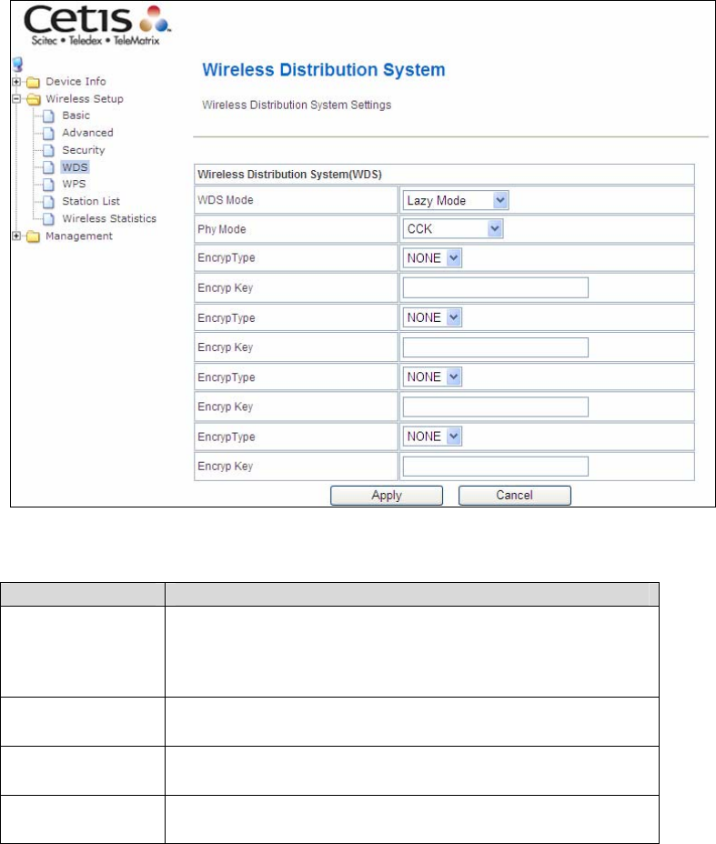
5.4 WDS
Wireless Distribution System (WDS)
WDS Mode: There are four options, including Disable, Lazy Mode, Bridge
Mode, and Repeater Mode.
• Disable
Select Disable to disable the WDS mode.
• Lazy Mode
Field Description
WDS Mode: Select Lazy Mode. The EXA100WDS Lazy mode
allows the other WDS bridge / repeater mode to
link automatically.
Phy Mode: It provides 4 options, including CCK, OFDM,
HTMIX, and GREENFIELD.
Encryp Type: It provides 4 options, including None, WEP, TKIP,
and AES.
Encryp Key: It provides 4 AP MAC Addresses. Input the MAC
address of the other APs.
24
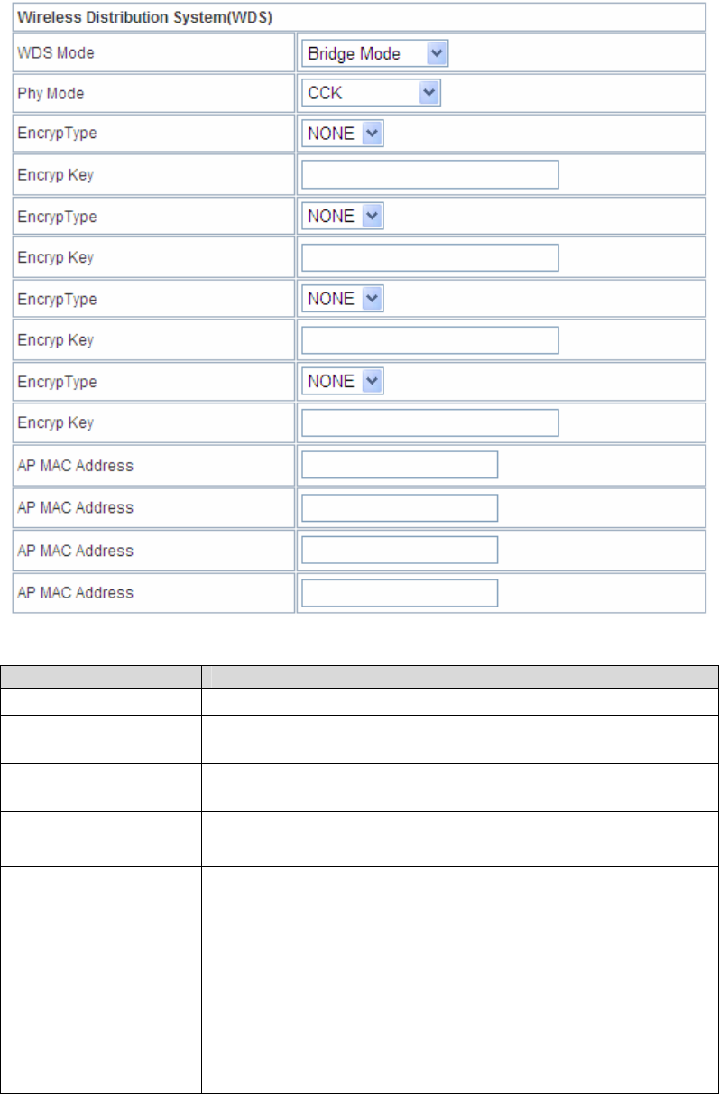
• Bridge Mode/ Repeater Mode
Field Description
WDS Mode: Select Bridge Mode or Repeater Mode.
Phy Mode: It provides 4 options, including CCK, OFDM, HTMIX,
and GREENFIELD.
Encryp Type: It provides 4 options, including None, WEP, TKIP,
and AES.
AP MAC Address:
It provides 4 AP MAC Addresses. Input the MAC
address of the other APs.
WDS
(Wireless
Distribution
System)
Allows access points to communicate with one another
wirelessly in a standardized way. It can also simplify
the network infrastructure by reducing the amount of
cabling required. Basically the access points will act as
a client and an access point at the same time.
WDS is incompatible with WPA. Both features cannot
be used at the same time. A WDS link is bi-
directional, so the AP must know the MAC address of
the other AP, and the other AP must have a WDS link
back to the AP.

25
Dynamically assigned and rotated encryption key are
not supported in a WDS connection. This means that
WPA and other dynamic key assignment technologies
may not be used.
Only Static WEP keys may be used in a WDS
connection, including any STAs that are associated
with a WDS repeating AP.
Input the MAC address of the other APs that you want
to link to and click enable.
Supports up to 4 point to multipoint WDS links, check
Enable WDS and then enable on the MAC addresses
Example of a WDS topology:
AP1 <-- WDS --> Master AP (our AP) <-- WDS --> AP3<-- WDS -->
AP4
26
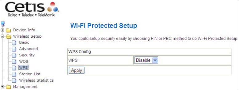
5.5 WPS
You can enable or disable the WPS function on this page.
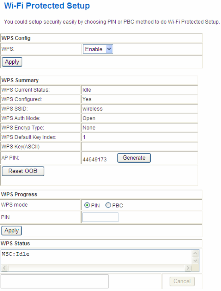
Select Enable from the WPS drop-down list. Click Apply and the following
page will be displayed.
27
28
WPS Summary
It displays the WPS information, such as WPS Current Status, WPS
Configured, and WPS SSID.
Reset OOB: Reset to out of box (OoB) configuration.
WPS Progress
WPS mode: There are two ways for you to enable the WPS function: PIN,
PBC. You can use a push button configuration (PBC) on the Wi-Fi router. If
there is no button, input a 4- or 8-digit PIN code. Each STA supporting WPS
comes with a hard-coded PIN code.
PIN: If you select PIN mode, you need to input the PIN number in the field.
WPS Status
It displays the information about WPS status.
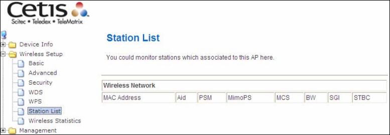
5.6 Station List
On this page, you can easily identify the connected wireless stations. It
automatically observes the ID of the connected wireless station (if specified),
MAC address, SSID, and current status.
29
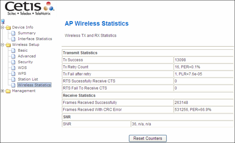
5.7 AP Wireless Statistics
This page shows the Wireless Statistics of EXA100.
30
Chapter 6 Management - Configuration
Backup
To save the current configuration to a file on your PC, click Backup
Settings. You will be prompted for backup file location. This file can later
be used to recover settings on the Update Settings screen, as described
below.
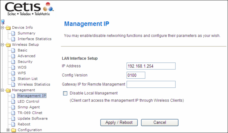
6.1 Management IP
IP Address:
Web LAN IP address for management.
Config Version:
Shows the current configuration version. The EXA100 can update the
configuration automatically via TFTP server.
Gateway IP for remote management:
Disable Local management:
When disable the local management (ticking the checkbox ;.), user can not
access web page via Wireless.
31
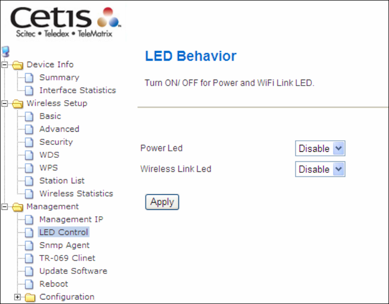
6.2 LED Control
SelectDisableorEnablefromthedrop‐downmenuandclicktheApplybutton.
32
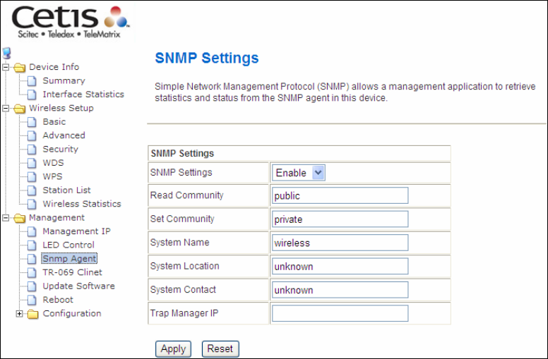
6.3 SNMP Agent
Simple Network Management Protocol (SNMP) allows a management
application to retrieve statistics and status from the SNMP agent in this
device. Select Enable from the drop-down menu, configure options, and
click Apply to activate SNMP.
33
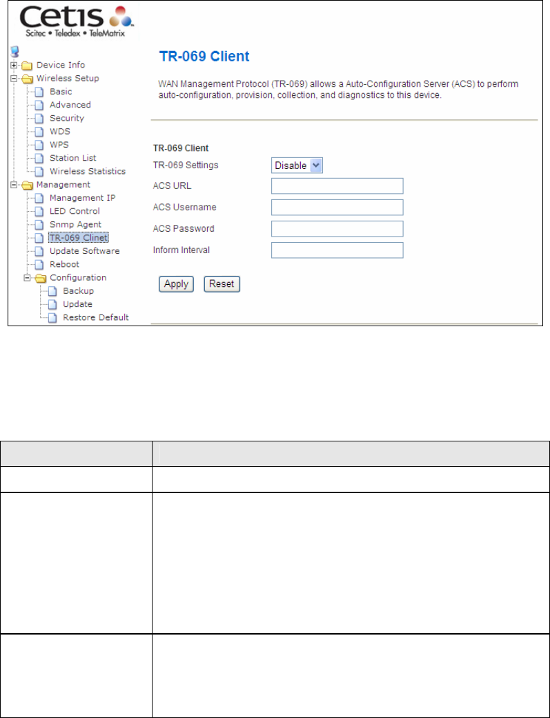
6.4 TR-069 Client
WAN Management Protocol (TR-069) allows an Auto-Configuration Server
(ACS) to perform auto-configuration, provision, collection, and diagnostics
to this device. Select desired values and click Apply/Save to configure TR-
069 client options.
The table below is provided for ease of reference.
Field Description
TR-069 Settings Select Enable/Disable from the drop-down menu.
ACS URL URL for the WiFi AP to connect to the ACS using the
WIFI AP WAN Management Protocol. This parameter
MUST be in the form of a valid HTTP or HTTPS URL. An
HTTPS URL indicates that the ACS supports SSL. The
“host” portion of this URL is used by the WIFI AP for
validating the certificate from the ACS when using
certificate-based authentication.
ACS User Name Username used to authenticate the WIFI AP when
making a connection to the ACS using the WIFI AP
WAN Management Protocol. This username is used
only for HTTP-based authentication of the WIFI AP.

34
Field Description
ACS Password Password used to authenticate the WIFI AP when
making a connection to the ACS using the WIFI AP
WAN Management Protocol. This password is used
only for HTTP-based authentication of the WIFI AP.
Inform Interval The duration in seconds of the interval for which the
WIFI AP MUST attempt to connect with the ACS and
call the Inform method.
35
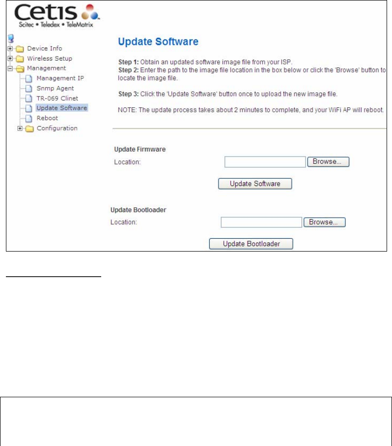
6.5 Update Software
This option allows for firmware upgrades from a locally stored file.
Update Firmware
STEP 1: Obtain an updated software image file from your ISP.
STEP 2: Enter the path and filename of the firmware image file in the
Software File Name field or click the Browse button to locate
the image file.
STEP 3: Click the Update Software button once to upload and install the
file.
NOTE: The update process will take about 2 minutes to complete. The
device will reboot and the browser window will refresh to the
default screen upon successful installation. It is recommended
that you compare the Software Version on the

36
Chapter 4 Device Information screen with the firmware version
installed, to confirm the installation was successful.
37
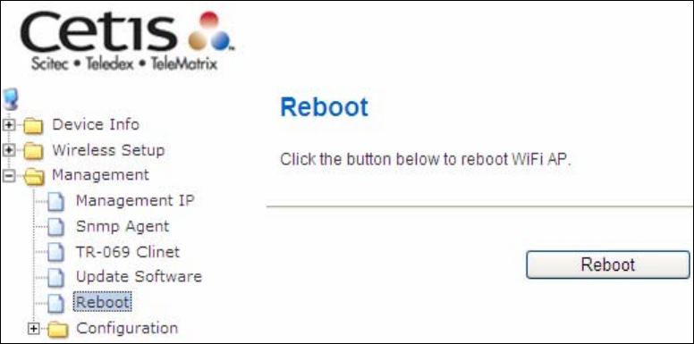
6.6 Reboot
To save the current configuration and reboot the router, click Save/Reboot.
NOTE: You may need to close the browser window and wait for 2 minutes
before reopening it. It may also be necessary, to reset your PC IP
configuration.
38
6.7 Configuration
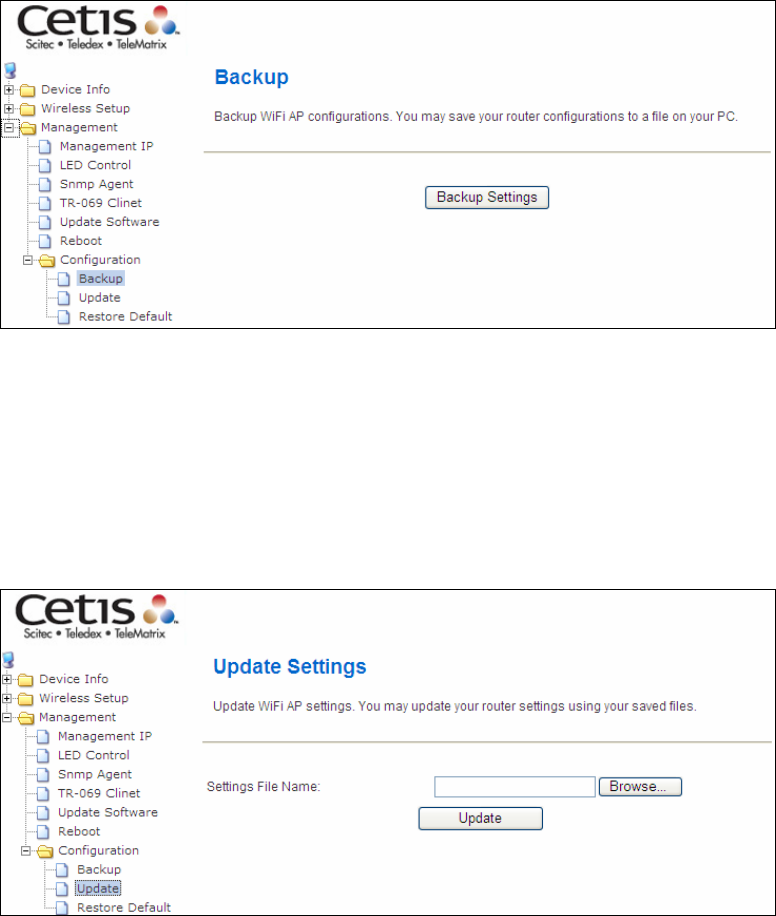
6.7.1 Backup Settings
To save the current configuration to a file on your PC, click Backup
Settings. You will be prompted for backup file location. This file can later
be used to recover settings on the Update Settings screen, as described
below.
6.7.2 Update Settings
This option recovers configuration files previously saved using Backup
Settings. Enter the file name (including folder path) in the Settings File
Name box, or press Browse… to search for the file, then click Update
Settings to recover settings.
39
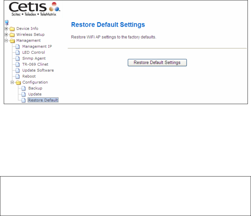
6.7.3 Restore Default
Click Restore Default Settings to restore factory default settings.
After Restore Default Settings is clicked, close the browser and wait for 2
minutes before reopening it. It may also be necessary, to reconfigure your
PC IP configuration to match any new settings.
NOTE: This entry has the same effect as the Reset button. The EXA100
board hardware and the boot loader support the reset to default.
If the Reset button is continuously pressed for more than 5
seconds, the boot loader will erase the configuration data saved in
flash memory.
40
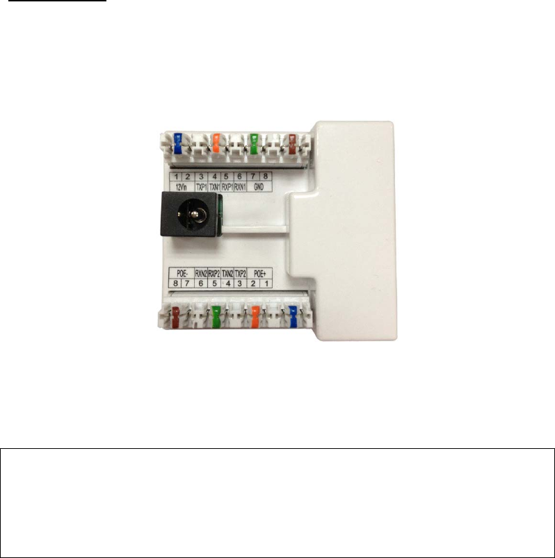
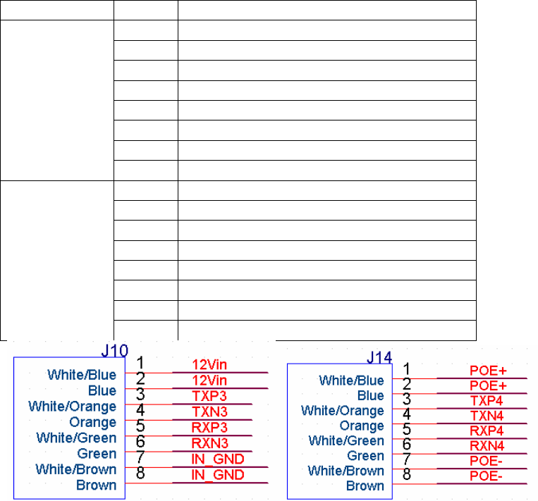
Appendix A - Pin Assignments
ETHERNET Ports (RJ45)
ETHERNET LAN Ports (10/100Base-T)
Connection # PIN # Descriptions
1 +12Vdc Input
2 +12Vdc Input
3 Ethernet TX (+)/LAN1
4 Ethernet TX (-)/LAN1
5 Ethernet RX (+)/LAN1
6 Ethernet RX (-)/LAN1
7 Ground
J10
8 Ground
1 PoE (+) Input
2 PoE (+) Input
3 Ethernet TX (+)/LAN2
4 Ethernet TX (-)/LAN2
5 Ethernet RX (+)/LAN2
6 Ethernet RX (-)/LAN2
7 PoE (-) Input
J14
8 PoE (-) Input
41
Appendix B – Specifications
Hardware Interface
z Power Jack X 1,
z Two Punch IDC connectors
z Reset button X 1,
z Active LED X 2,
z Antenna internal
LAN Interface
z IEEE 802.3, IEEE 802.3u
ADSL
z ADSL standard ITU-T G.992.5, ITU-T G.992.3, ITU-T G.992.1, ANSI
T1.413 Issue 2,
z G.992.5 (ADSL2+):
z G.992.3 (ADSL2):
z G.DMT
WLAN
z
IEEE
802.11n,
backward
compatible
with
802.11g/b
z
64,
128-bit
Wired
Equivalent
Privacy
(WEP)
Da
t
a
Encryption
z
11
Channels
(US,
Canada)/
13
Channels
(Europe)/
14 Channels (Japan)
z
Up
to
300
Mbps
data
rate
z
WPA
/
WPA2
z
IEEE
802.1x
z
RF
operating
frequency
:
2.412-2.497
GHz
(2.4
GHz
ISM Band)
z dd
RF
output
power:
15dBm
z
Antenna
gain:
2dBi
Bridge Functions
z IEEE 802.1d
z VLAN support
z
Spanning
Tree
Algorithm
z IGMP Proxy

42
Management
z SNMP, Telnet, Web-based management, Configuration backup and
restoration
z
RFC1213
Management
information
base
for
Network management
of
TCP/IP-based
internets
:
MIB-II
z Software upgrade via HTTP
Power Supply
z
Input: 100 - 240 Vac
z
Vac/ 50-60Hz
z
Output:
12 Vdc / 1 A
Certifications
z
EN 55022 + EN55024
z
EN 300328
z
EN 301489-1 / -17
z
EN 60950-1
z
Power Saving
z
WEEE
z
RoHS
z
REACH
Packing Accessories:
z
Module x 3
z
Quarter Blank spec x 2
z
KeyStone Jack x 1
z ConnectorSwitchx1
z
QIG for troubleshooting
z
Water-proof sealed PE bag (for ATU-R&QIG) x 1
NOTE: Specifications are subject to change without
notice

43
Appendix C –Parameter Rules
Setting
parameters
in Web GUI
Settings
parameters in
Config file
value default
Radio On/Off RadioOff=0 0: disable
1: enable 0
Network
Name(SSID) SSID1=wireless wireless
Multiple
SSID1 SSID2= blank
Multiple
SSID2 SSID3= blank
Multiple
SSID3 SSID4= blank
Multiple
SSID4 SSID5= blank
Hidden HideSSID=
(SSID1;SSID2;SSID3;SSID4;SSID5)
0: disable
1: enable(hide) 0;1;1;1;1
Isolated NoForwarding=
(SSID1;SSID2;SSID3;SSID4;SSID5)
0: disable
1: enable 1;0;0;0;0
Frequency
(Channel) Channel=0
AutoChannelSelect=1
Network
Mode-11b/g
mixed mode WirelessMode=0
FixedTxMode=OFDM
0
Network
Mode-11b
only WirelessMode=1
FixedTxMode=CCK 1
Network
Mode-11g
only WirelessMode=4
FixedTxMode=OFDM
4
Network
Mode-
11b/g/n
mixed mode
WirelessMode=9
FixedTxMode=HT 9
Operating
Mode HT_OpMode=0 0: Mixed Mode
1: Green Field 0
Channel
BandWidth HT_BW=1 0: 20
1: 20/40 1
Guard
Interval HT_GI=1 0: long
1: Auto 1
MCS HT_MCS=33 (SSID1;SSID2;SSID3;SSID4;SSID5)
from: 1-15 and 32
33: Auto 33
Reverse
Direction
Grant(RDG) HT_RDG=1 1
STBC HT_STBC=1 1
Aggregation
MSDU(A-
MSDU) HT_AMSDU=0 0
Auto Block
ACK HT_AutoBA=1 1
Decline BA
Request HT_BADecline=0 0
Basic
Wireless
Setting
HT Disallow
TKIP HT_DisallowTKIP=1
0: disable
1: enable
1

44
Network
Mode-11n
only(2.4G) WirelessMode=6 6
Operating
Mode HT_OpMode=0 0: Mixed Mode
1: Green Field 0
Channel
BandWidth HT_BW=1 0: 20
1: 20/40 1
Guard
Interval HT_GI=1 0: long
1: Auto 1
MCS HT_MCS=33 (SSID1;SSID2;SSID3;SSID4;SSID5)
from: 1-15 and 32
33: Auto 33
Reverse
Direction
Grant(RDG) HT_RDG=1 1
STBC HT_STBC=1 1
Aggregation
MSDU(A-
MSDU) HT_AMSDU=0 0
Auto Block
ACK HT_AutoBA=1 1
Decline BA
Request HT_BADecline=0 0
HT Disallow
TKIP HT_DisallowTKIP=1
0: disable
1: enable
1
HT TxStream HT_TxStream=2 from:1-2 2
HT RxStream HT_RxStream=2 from:1-2 2
BG
Protection
Mode BGProtection=0 0: Auto
1: On
2: Off 0
Beacon
Interval BeaconPeriod=100 range 20 - 999 100
Data Beacon
Rate (DTIM) DtimPeriod=1 range 1 - 255 1
Fragment
Threshold FragThreshold=2346
range 256 - 2346 2346
RTS
Threshold RTSThreshold=2347
range 1 - 2347 2347
TX Power TxPower=100 range 1 100
Short
Preamble TxPreamble=1 1
Short Slot ShortSlot=1 1
Tx Burst TxBurst=1 1
Pkt_Aggregat
e PktAggregate=1 1
Advance
d
Wireless
Settings
IEEE
802.11H
Support IEEE80211H=0
0: disable
1: enable
0

45
Country
Code
CountryRegion=0
CountryRegionABand
=7
CountryCode=US
US:
CountryRegion=0
CountryRegionABand=7
CountryCode=US
JP:
CountryRegion=5
CountryRegionABand=6
CountryCode=JP
FR:
CountryRegion=1
CountryRegionABand=2
CountryCode=FR
TW:
CountryRegion=0
CountryRegionABand=8
CountryCode=TW
IE:
CountryRegion=1
CountryRegionABand=1
CountryCode=IE
HK:
CountryRegion=1
CountryRegionABand=0
CountryCode=HK
NONE:
CountryRegion=5
CountryRegionABand=7
CountryCode=
US
WMM
Capable WmmCapable=1 1
APSD Capable APSDCapable=0 0
DLS Capable DLSCapable=0 0
Multicast-to-
Unicast M2UEnabled=0
0: disable
1: enable
0
Security
Mode-Disable
AuthMode=OPEN
EncrypType=NONE
Security
Mode-
OPENWEP AuthMode=OPEN
EncrypType=WEP
Default Key DefaultKeyID=1 (SSID1;SSID2;SSID3;SSID4;SSID5)
from:1-4 1,1,1,1,1
WEP Key 1 Key1Str1=
Key1Type=0
WEP Key 2 Key2Str1=
Key2Type=0
WEP Key 3 Key3Str1=
Key3Type=0
WEP Key 4 Key4Str1=
Key4Type=0
(SSID1;SSID2;SSID3;SSID4;SSID5)
keyType: 0 - 1
0: Hex
1: ASCII
KeyStr1=blan
k
KeyType=0
Security
Mode-
SHAREDWEP AuthMode=SHARED
EncrypType=WEP
Default Key DefaultKeyID=1 (SSID1;SSID2;SSID3;SSID4;SSID5)
from:1-4 1,1,1,1,1
WEP Key 1 Key1Str1=
Key1Type=0 (SSID1;SSID2;SSID3;SSID4;SSID5)
keyType: 0 - 1 KeyStr1=blan
k

46
WEP Key 2 Key2Str1=
Key2Type=0
WEP Key 3 Key3Str1=
Key3Type=0
WEP Key 4 Key4Str1=
Key4Type=0
0: Hex
1: ASCII KeyType=0
Security
Mode-
WEPAUTO AuthMode=WEPAUTO
EncrypType=WEP
Default Key DefaultKeyID=1 (SSID1;SSID2;SSID3;SSID4;SSID5)
from:1-4 1,1,1,1,1
WEP Key 1 Key1Str1=
Key1Type=0
WEP Key 2 Key2Str1=
Key2Type=0
WEP Key 3 Key3Str1=
Key3Type=0
WEP Key 4 Key4Str1=
Key4Type=0
(SSID1;SSID2;SSID3;SSID4;SSID5)
keyType: 0 - 1
0: Hex
1: ASCII
KeyStr1=blan
k
KeyType=0,0,
0,0,0
Security
Mode-WPA AuthMode=WPA
WPA
Algorithms EncrypType= (SSID1;SSID2;SSID3;SSID4;SSID5)
TKIP or AES
Key Renewal
Interval RekeyInterval=3600
(SSID1;SSID2;SSID3;SSID4;SSID5)
0 - 4194303 3600
IP Address RADIUS_Server= blank
Port RADIUS_Port=1812 (SSID1;SSID2;SSID3;SSID4;SSID5) 1812
Shared Secret
RADIUS_Key1=
RADIUS_Key2=
RADIUS_Key3=
RADIUS_Key4=
RADIUS_Key5=
Session
Timeout session_timeout_inter
val=0 (SSID1;SSID2;SSID3;SSID4;SSID5) 0
Security
Mode-WPA-
PSK AuthMode=WPAPSK
WPA
Algorithms EncrypType= (SSID1;SSID2;SSID3;SSID4;SSID5)
TKIP or AES
Pass Phrase
WPAPSK1=
WPAPSK2=
WPAPSK3=
WPAPSK4=
WPAPSK5=
Key Renewal
Interval RekeyInterval=3600
(SSID1;SSID2;SSID3;SSID4;SSID5)
0 - 4194303 3600
Security
Mode-WPA2 AuthMode=WPA2
WPA
Algorithms EncrypType= (SSID1;SSID2;SSID3;SSID4;SSID5)
TKIP or AES
Key Renewal
Interval RekeyInterval=3600
(SSID1;SSID2;SSID3;SSID4;SSID5)
0 - 4194303 3600

47
PMK Cache
Period PMKCachePeriod=10
10
Pre-
Authentication
PreAuth=0 0
IP Address RADIUS_Server= (SSID1;SSID2;SSID3;SSID4;SSID5) blank
Port RADIUS_Port=1812 (SSID1;SSID2;SSID3;SSID4;SSID5) 1812
Shared Secret
RADIUS_Key1=
RADIUS_Key2=
RADIUS_Key3=
RADIUS_Key4=
RADIUS_Key5=
blank
Session
Timeout session_timeout_inter
val=0 (SSID1;SSID2;SSID3;SSID4;SSID5) 0
Security
Mode-WPA2-
PSK AuthMode=WPA2PSK
WPA
Algorithms EncrypType= (SSID1;SSID2;SSID3;SSID4;SSID5)
TKIP or AES
Pass Phrase
WPAPSK1=
WPAPSK2=
WPAPSK3=
WPAPSK4=
WPAPSK5=
Key Renewal
Interval RekeyInterval=3600
(SSID1;SSID2;SSID3;SSID4;SSID5)
0 - 4194303 3600
Security
Mode-
WPAPSKWPA
2PSK
AuthMode=WPAPSKW
PA2PSK
WPA
Algorithms EncrypType= (SSID1;SSID2;SSID3;SSID4;SSID5)
TKIP or AES
Pass Phrase
WPAPSK1=
WPAPSK2=
WPAPSK3=
WPAPSK4=
WPAPSK5=
Key Renewal
Interval RekeyInterval=3600
(SSID1;SSID2;SSID3;SSID4;SSID5)
0 - 4194303 3600
Security
Mode-
WPA1WPA2 AuthMode=WPA1WPA
2
WPA
Algorithms EncrypType= (SSID1;SSID2;SSID3;SSID4;SSID5)
TKIP or AES blank
Key Renewal
Interval RekeyInterval=3600
(SSID1;SSID2;SSID3;SSID4;SSID5)
0 - 4194303 3600
IP Address RADIUS_Server= (SSID1;SSID2;SSID3;SSID4;SSID5) blank
Port RADIUS_Port=1812 (SSID1;SSID2;SSID3;SSID4;SSID5) 1812
Shared Secret
RADIUS_Key1=
RADIUS_Key2=
RADIUS_Key3=
RADIUS_Key4=
RADIUS_Key5=
blank
Session
Timeout session_timeout_inter
val=0 (SSID1;SSID2;SSID3;SSID4;SSID5) 0

48
Security
Mode-802.1x AuthMode=OPEN
EncrypType=WEP
802.1x WEP IEEE8021X= blank
IP Address RADIUS_Server= (SSID1;SSID2;SSID3;SSID4;SSID5) blank
Port RADIUS_Port=1812 (SSID1;SSID2;SSID3;SSID4;SSID5) 1812
Shared Secret
RADIUS_Key1=
RADIUS_Key2=
RADIUS_Key3=
RADIUS_Key4=
RADIUS_Key5=
blank
Session
Timeout session_timeout_inter
val=0 (SSID1;SSID2;SSID3;SSID4;SSID5) 0
Policy AccessPolicy0=0 0: Disable
1: Allow
2: Reject 0
Add a station
Mac AccessControlList0=
blank
WDS Mode-
Disable WdsEnable=0 0
WDS Mode-
Lazy Mode WdsEnable=4 4
Phy Mode WdsPhyMode=
CCK;CCK;CCK;CCK
OFDM;OFDM;OFDM;OFDM
HTMIX;HTMIX;HTMIX;HTMIX
GREENFIELD;GREENFIELD;GREENFIELD
;GREENFIELD
CCK;CCK;CCK
;CCK
EncrypType WdsEncrypType=
(SSID1;SSID2;SSID3;SSID4;SSID5)
NONE,WEP,TKIP,AES NONE
Encryp Key
Wds0Key=
Wds1Key=
Wds2Key=
Wds3Key=
blank
WDS Mode-
Bridge Mode WdsEnable=2 2
Phy Mode WdsPhyMode=
CCK;CCK;CCK;CCK
OFDM;OFDM;OFDM;OFDM
HTMIX;HTMIX;HTMIX;HTMIX
GREENFIELD;GREENFIELD;GREENFIELD
;GREENFIELD
CCK;CCK;CCK
;CCK
EncrypType WdsEncrypType=
(SSID1;SSID2;SSID3;SSID4;SSID5)
NONE,WEP,TKIP,AES NONE
Encryp Key
Wds0Key=
Wds1Key=
Wds2Key=
Wds3Key=
blank
AP MAC
Address WdsList= blank
WDS Mode-
Repeater
Mode WdsEnable=3 3
Wireless
Distribut
ion
System
Phy Mode WdsPhyMode=
CCK;CCK;CCK;CCK
OFDM;OFDM;OFDM;OFDM
HTMIX;HTMIX;HTMIX;HTMIX
GREENFIELD;GREENFIELD;GREENFIELD
;GREENFIELD
CCK;CCK;CCK
;CCK

49
EncrypType WdsEncrypType=
(SSID1;SSID2;SSID3;SSID4;SSID5)
NONE,WEP,TKIP,AES NONE
Encryp Key
Wds0Key=
Wds1Key=
Wds2Key=
Wds3Key=
blank
AP MAC
Address WdsList= blank
Wi-Fi
Protecte
d Setup WPS WscModeOption=7 default is 7
7=enable
0=disable 7
Setting parameters Web GUI Config file value default
IP Address lan_ipaddr=192.168.1.254 192.168.1.254
Gateway IP for Remote
Management lan_gateway=0.0.0.0 0.0.0.0
Disable Local Management lan_filter=0 0: disable
1: enable 0
Management IP
Config Version ConfigVersion=0100 0100
Power Led PwrLedEnabled=0 0
LED Behavior Wireless Link Led WlanLinkLedEnabled=0
0: disable
1: enable 0
SNMP Settings SNMPEnabled=1 0: disable
1: enable 1
Read Community SNMPREADCOMM=public public
Set Community SNMPWRITCOMM=private private
System Name SNMPpsysname=wireless wireless
System Location SNMPpsyslocation=unknown
unknown
System Contact SNMPpsyscontact=unknown
unknown
SNMP Settings
Trap Manager IP SNMPtrap=0.0.0.0 0.0.0.0
TR-069 Settings TR69Enabled=0 0: disable
1: enable 0
ACS URL TR69ACSurl= blank
ACS Username TR69Username= blank
ACS Password TR69Password= blank
TR-069 Client
Inform Interval TR69InformInterval= blank