CHM Sdk.arx.cpp.dev
User Manual: CHM sdk.arx.cpp.dev
Open the PDF directly: View PDF ![]() .
.
Page Count: 168 [warning: Documents this large are best viewed by clicking the View PDF Link!]
- Contents
- Before You Begin
- Drawing Sets
- Drawing Set Sample
- Queries
- Query Sample
- Property Alteration
- Property Alteration Sample
- Designing Queryable Custom Objects
- Custom Object Protocol Extensions
- Data Sources
- Object Data
- Object Data Samples
- Coordinate Systems
- Converting Coordinates
- Feature Classification
- Object Filters
- Import-Export
- Oracle Spatial Data
- Oracle Spatial Samples
- Oracle Spatial Sample Projects
- Topology
- Centroids
- Drawing Cleanup
- Annotation
- Display Manager
- User Management
- Map Plotting and Publishing
- Managed Wrapper Classes
- Notes, Tips, and Warnings
- Index

AutoCAD®Map 3D 2009
ObjectARX C++
Developer's Guide
April 2008
©2008 Autodesk, Inc. All Rights Reserved. Except as otherwise permitted by Autodesk, Inc., this publication, or parts thereof, may not be
reproduced in any form, by any method, for any purpose.
Certain materials included in this publication are reprinted with the permission of the copyright holder.
Trademarks
The following are registered trademarks or trademarks of Autodesk, Inc., in the USA and other countries: 3DEC (design/logo), 3December,
3December.com, 3ds Max, ActiveShapes, Actrix, ADI, Alias, Alias (swirl design/logo), AliasStudio, Alias|Wavefront (design/logo), ATC, AUGI,
AutoCAD, AutoCAD Learning Assistance, AutoCAD LT, AutoCAD Simulator, AutoCAD SQL Extension, AutoCAD SQL Interface, Autodesk, Autodesk
Envision, Autodesk Insight, Autodesk Intent, Autodesk Inventor, Autodesk Map, Autodesk MapGuide, Autodesk Streamline, AutoLISP, AutoSnap,
AutoSketch, AutoTrack, Backdraft, Built with ObjectARX (logo), Burn, Buzzsaw, CAiCE, Can You Imagine, Character Studio, Cinestream, Civil
3D, Cleaner, Cleaner Central, ClearScale, Colour Warper, Combustion, Communication Specification, Constructware, Content Explorer,
Create>what's>Next> (design/logo), Dancing Baby (image), DesignCenter, Design Doctor, Designer's Toolkit, DesignKids, DesignProf, DesignServer,
DesignStudio, Design|Studio (design/logo), Design Your World, Design Your World (design/logo), DWF, DWG, DWG (logo), DWG TrueConvert,
DWG TrueView, DXF, EditDV, Education by Design, Exposure, Extending the Design Team, FBX, Filmbox, FMDesktop, Freewheel, GDX Driver,
Gmax, Heads-up Design, Heidi, HOOPS, HumanIK, i-drop, iMOUT, Incinerator, IntroDV, Inventor, Inventor LT, Kaydara, Kaydara (design/logo),
LocationLogic, Lustre, Maya, Mechanical Desktop, MotionBuilder, Mudbox, NavisWorks, ObjectARX, ObjectDBX, Open Reality, Opticore,
Opticore Opus, PolarSnap, PortfolioWall, Powered with Autodesk Technology, Productstream, ProjectPoint, ProMaterials, Reactor, RealDWG,
Real-time Roto, Recognize, Render Queue, Reveal, Revit, Showcase, ShowMotion, SketchBook, SteeringWheels, StudioTools, Topobase, Toxik,
ViewCube, Visual, Visual Bridge, Visual Construction, Visual Drainage, Visual Hydro, Visual Landscape, Visual Roads, Visual Survey, Visual Syllabus,
Visual Toolbox, Visual Tugboat, Visual LISP, Voice Reality, Volo, Wiretap, and WiretapCentral
The following are registered trademarks or trademarks of Autodesk Canada Co. in the USA and/or Canada and other countries: Backburner,
Discreet, Fire, Flame, Flint, Frost, Inferno, Multi-Master Editing, River, Smoke, Sparks, Stone, and Wire
All other brand names, product names or trademarks belong to their respective holders.
Disclaimer
THIS PUBLICATION AND THE INFORMATION CONTAINED HEREIN IS MADE AVAILABLE BY AUTODESK, INC. "AS IS." AUTODESK, INC. DISCLAIMS
ALL WARRANTIES, EITHER EXPRESS OR IMPLIED, INCLUDING BUT NOT LIMITED TO ANY IMPLIED WARRANTIES OF MERCHANTABILITY OR
FITNESS FOR A PARTICULAR PURPOSE REGARDING THESE MATERIALS.
Published by:
Autodesk, Inc.
111 Mclnnis Parkway
San Rafael, CA 94903, USA
Contents
Chapter 1 Before You Begin . . . . . . . . . . . . . . . . . . . . . . . . . . 1
Sources of Information . . . . . . . . . . . . . . . . . . . . . . . . . . . 1
Compatability of SDKs . . . . . . . . . . . . . . . . . . . . . . . . . . . 2
Typographic Conventions . . . . . . . . . . . . . . . . . . . . . . . . . 2
Chapter 2 Drawing Sets . . . . . . . . . . . . . . . . . . . . . . . . . . . . 3
Drawing Sets Detail . . . . . . . . . . . . . . . . . . . . . . . . . . . . . 3
Chapter 3 Drawing Set Sample . . . . . . . . . . . . . . . . . . . . . . . . 5
Drawing Set Sample . . . . . . . . . . . . . . . . . . . . . . . . . . . . . 5
Chapter 4 Queries . . . . . . . . . . . . . . . . . . . . . . . . . . . . . . 11
Queries Detail . . . . . . . . . . . . . . . . . . . . . . . . . . . . . . . 11
Chapter 5 Query Sample . . . . . . . . . . . . . . . . . . . . . . . . . . . 15
Query Sample Code . . . . . . . . . . . . . . . . . . . . . . . . . . . . 16
Chapter 6 Property Alteration . . . . . . . . . . . . . . . . . . . . . . . . 19
Property Alteration . . . . . . . . . . . . . . . . . . . . . . . . . . . . 19
iii
Chapter 7 Property Alteration Sample . . . . . . . . . . . . . . . . . . . . 23
Property Alteration Sample . . . . . . . . . . . . . . . . . . . . . . . . 23
Chapter 8 Designing Queryable Custom Objects . . . . . . . . . . . . . . 33
Designing Queryable Custom Objects Details . . . . . . . . . . . . . . 33
Chapter 9 Custom Object Protocol Extensions . . . . . . . . . . . . . . . 35
Chapter 10 Data Sources . . . . . . . . . . . . . . . . . . . . . . . . . . . . 37
Chapter 11 Object Data . . . . . . . . . . . . . . . . . . . . . . . . . . . . 39
Chapter 12 Object Data Samples . . . . . . . . . . . . . . . . . . . . . . . 41
Creating an Object Data Table . . . . . . . . . . . . . . . . . . . . . . 41
Attaching Object Data . . . . . . . . . . . . . . . . . . . . . . . . . . . 42
Traversing Object Data . . . . . . . . . . . . . . . . . . . . . . . . . . 44
Adding or Changing Object Data . . . . . . . . . . . . . . . . . . . . . 45
Chapter 13 Coordinate Systems . . . . . . . . . . . . . . . . . . . . . . . . 49
Coordinate Systems Details . . . . . . . . . . . . . . . . . . . . . . . . 49
Chapter 14 Converting Coordinates . . . . . . . . . . . . . . . . . . . . . . 51
Converting Coordinates . . . . . . . . . . . . . . . . . . . . . . . . . . 51
Chapter 15 Feature Classification . . . . . . . . . . . . . . . . . . . . . . . 55
Feature Classification Detail . . . . . . . . . . . . . . . . . . . . . . . . 55
Chapter 16 Object Filters . . . . . . . . . . . . . . . . . . . . . . . . . . . 65
Object Filters Detail . . . . . . . . . . . . . . . . . . . . . . . . . . . . 65
Chapter 17 Import-Export . . . . . . . . . . . . . . . . . . . . . . . . . . . 69
Import-Export Detail . . . . . . . . . . . . . . . . . . . . . . . . . . . 69
Chapter 18 Oracle Spatial Data . . . . . . . . . . . . . . . . . . . . . . . . 79
Oracle Spatial Data Detail . . . . . . . . . . . . . . . . . . . . . . . . . 79
Chapter 19 Oracle Spatial Samples . . . . . . . . . . . . . . . . . . . . . . 85
Connecting to an Oracle Spatial Database . . . . . . . . . . . . . . . . 85
iv | Contents
Subclassing Custom Reactors . . . . . . . . . . . . . . . . . . . . . . . 88
Exporting to an Oracle Spatial Database . . . . . . . . . . . . . . . . . 89
Importing from an Oracle Spatial Database . . . . . . . . . . . . . . . 93
Getting Corresponding IDs . . . . . . . . . . . . . . . . . . . . . . . . 95
Filtering Objects . . . . . . . . . . . . . . . . . . . . . . . . . . . . . . 99
Chapter 20 Oracle Spatial Sample Projects . . . . . . . . . . . . . . . . . 103
Importing From an Oracle Spatial Database . . . . . . . . . . . . . . . 103
Storing Block Definitions in an Oracle Spatial Database . . . . . . . . 105
Storing Block Attribute Positions in an Oracle Spatial Database . . . . 106
Chapter 21 Topology . . . . . . . . . . . . . . . . . . . . . . . . . . . . . 109
Topology Detail . . . . . . . . . . . . . . . . . . . . . . . . . . . . . 109
Chapter 22 Centroids . . . . . . . . . . . . . . . . . . . . . . . . . . . . . 129
Creating Centroids . . . . . . . . . . . . . . . . . . . . . . . . . . . . 129
Chapter 23 Drawing Cleanup . . . . . . . . . . . . . . . . . . . . . . . . 131
Drawing Cleanup Details . . . . . . . . . . . . . . . . . . . . . . . . 131
Chapter 24 Annotation . . . . . . . . . . . . . . . . . . . . . . . . . . . . 137
Annotation Details . . . . . . . . . . . . . . . . . . . . . . . . . . . . 137
Chapter 25 Display Manager . . . . . . . . . . . . . . . . . . . . . . . . . 147
Chapter 26 User Management . . . . . . . . . . . . . . . . . . . . . . . . 149
User Management Detail . . . . . . . . . . . . . . . . . . . . . . . . . 149
Chapter 27 Map Plotting and Publishing . . . . . . . . . . . . . . . . . . 153
Map Plotting and Publishing Detail . . . . . . . . . . . . . . . . . . . 153
Chapter 28 Managed Wrapper Classes . . . . . . . . . . . . . . . . . . . 155
Managed Wrapper Classes Detail . . . . . . . . . . . . . . . . . . . . 155
Chapter 29 Notes, Tips, and Warnings . . . . . . . . . . . . . . . . . . . . 157
Colors . . . . . . . . . . . . . . . . . . . . . . . . . . . . . . . . . . 157
Index . . . . . . . . . . . . . . . . . . . . . . . . . . . . . . . 161
Contents | v
vi
Before You Begin
AutoCAD Map 3D ObjectARX Developer's Guide describes how to use ObjectARX classes to
automate and extend AutoCAD Map 3D.
AutoCAD Map 3D ObjectARX extends AutoCAD ObjectARX into the AutoCAD Map 3D
domain.
The ObjectARX and ObjectARX .NET APIs each cover most of AutoCAD Map 3D functionality.
But they don't cover Resource Service, Feature Service, or Mapping Service. These areas are
covered by the Geospatial Platform API, which is exposed as .NET only.
Sources of Information
To develop applications using AutoCAD Map 3D ObjectARX, you should be
familiar with AutoCAD ObjectARX and also the AutoCAD Map 3D and AutoCAD
applications.
Refer to...For information about...
AutoCAD ObjectARX Help, arxdoc.chm,
which is located in the docs folder of
AutoCAD Map 3D SDK installations.
AutoCAD ObjectARX
AutoCAD Map 3D Help, which is located
in the Help folder of AutoCAD Map 3D in-
stallations.
AutoCAD Map 3D and AutoCAD
AutodCAD Map 3D Help is especially useful for undestanding how AutoCAD
Map 3D models its domain. For understanding drawing sets and queries, for
example. Since detailed explanations of these paradigms are available in
AutoCAD Map 3D Help, AutoCAD Map 3D SDK Help explains them only briefly
1
1

or not at all. Before you attempt to automate or extend an AutoCAD Map 3D
feature, be sure to review the subject in AutoCAD Map 3D Help.
Compatability of SDKs
The AutoCAD Map 3D SDK must be installed in an existing AutoCAD SDK
installation, and the AutoCAD Map 3D SDK and AutoCAD SDK versions must
be compatible with each other and with the version of AutoCAD Map 3D that
you are extending. For example, the AutoCAD Map 3D 2008 SDK must be
installed into an existing AutoCAD 2008 SDK installation, and you need both
to build ObjectARX applications for AutoCAD Map 3D 2008.
Typographic Conventions
DescriptionText element
Text you enter at the AutoCAD Map 3D
command prompt.
bold sans serif
Names of files and directories.italic
Sample code.monospace font
NOTE Note All file names and directory paths in AutoCAD Map 3D are case
sensitive.
2 | Chapter 1 Before You Begin
Drawing Sets
The collection of drawings used in a particular project is the project's drawing set.
Drawing Sets Detail
When you save a project, AutoCAD Map 3D automatically saves references to
all the project's drawing set files in the project's DWG file.
You attach drawings to and detach drawings from a drawing set.
Attached Drawings
A drawing set is a tree of attached drawings. Any of the attached drawings can
have other drawings attached to them. The drawings that are not directly
attached to the root of the drawing set (at level 0 of the tree) are called nested
drawings.
You can use AcMapDrawingSet functions to edit and manipulate only drawings
that are directly attached to the drawing set at the root level (level 0) of the
drawing set. To access and edit drawings at deeper levels, use the functions of
the AcMapAttachedDrawing class.
A single drawing can be directly attached to the drawing set only once. However,
a single drawing can have multiple entries in the drawing set at nested levels 1
and deeper.
You can designate an attached drawing as active or inactive. When a query is
executed in the project, only the active drawings are considered. When you
work with object data in a project, open drawings instead of attaching them.
2
3
Drawing Set Reactors
You can attach a reactor to a drawing set. A drawing set reactor notifies an
application about drawing set-related events, such as attachment, detachment,
activation, or deactivation. Whenever the drawing set is modified, an
appropriate function of the reactor object is called before termination of the
zero level Map transaction.
Saving Attached Drawings
If, after modifying an attached drawing, you want to save the changes in the
source drawing, you must specify the set of drawing objects to be saved in a
save set.
Saving an attached drawing with its drawing objects is typically a three-part
procedure:
1Lock the drawing for writing using AcMapAttachedDrawing::LockForWrite.
2Clone the drawing objects that you wish to save using one of the
AcMapAttachedDrawing class's functions.
3Save the changes back to the drawing's source file using
AcMapAttachedDrawing::Save.
For More Information
For more information about drawing sets, see the UI documentation, Autodesk
Map Help.
4 | Chapter 2 Drawing Sets
Drawing Set Sample
Drawing Set Sample
The following sample demonstrates drawing set operations.
3
5
void editDSet()
{
AcMapSession *mapApi;
AcMapProject *pProj;
AcMapDrawingSet *pDSet;
char res[32];
do {
mapApi = AcMapGetSession();
if (mapApi == NULL)
{
acutPrintf ("\nCan't connect MAP") ;
break ;
}
if (mapApi->GetProject(pProj) == Adesk::kFalse)
{
break ;
}
if (pProj->GetDrawingSet(pDSet) == Adesk::kFalse)
{
acutPrintf ("\nCan't get drawing set") ;
break ;
}
do {
// Setup
printDSet(pDSet) ;
*res = EOS ;
acedInitGet(
0,
"eXit aTtach Detach Activate deaCtivate Settings
gettaBle aLiases View Preview Report Query Zoom") ;
if (acedGetKword(
"\naTtach/Detach/Activate/deaCtivate/
Settings/gettaBle/aLiases/View/Preview/Report/
Query/Zoom/<eXit>: ",
res
) == RTNORM)
{
if (*res == EOS || !(strcmp(res, "eXit")))
{
break ;
}
// Attach a drawing
else if (!strcmp(res, "aTtach"))
6 | Chapter 3 Drawing Set Sample
{
if (acedGetString (
1,
"Enter alias path: ",
res
) == RTNORM)
{
AcMapAttachedDrawing *pDwg = NULL ;
if (pDSet->AttachDrawing(pDwg, res) == AcMap::kOk)
{
delete pDwg ;
}
}
}
// Detach a drawing
else if (!strcmp(res, "Detach"))
{
acedGetString(1, "Enter drawing path ", res) ;
AcMapAttachedDrawing *pDwg = NULL ;
pDSet->DetachDrawing(res) ;
}
// Activate a drawing
else if (!strcmp(res, "Activate"))
{
acedGetString(1, "Enter drawing path ", res) ;
AcMapAttachedDrawing *pDwg = NULL ;
if (pDSet->GetDrawing(
pDwg,
res,
Adesk::kFalse
) == AcMap::kOk)
{
pDwg->Activate() ;
delete pDwg ;
}
}
// Deactivate a drawing
else if (!strcmp(res, "deaCtivate"))
{
acedGetString(1, "Enter drawing path ", res) ;
AcMapAttachedDrawing *pDwg = NULL ;
if (pDSet->GetDrawing(
pDwg,
Drawing Set Sample | 7
res,
Adesk::kFalse
) == AcMap::kOk)
{
pDwg->Deactivate() ;
delete pDwg ;
}
}
// Get a drawing's symbol table
else if (!strcmp(res, "gettaBle"))
{
acedGetString(1, "Enter drawing path ", res) ;
AcMapAttachedDrawing *pDwg = NULL ;
if (pDSet->GetDrawing(
pDwg,
res,
Adesk::kFalse
) == AcMap::kOk)
{
getTable(pDwg) ;
delete pDwg ;
}
}
// Edit a drawing's settings
else if (!strcmp(res, "Settings"))
{
acedGetString(1, "Enter drawing path ", res) ;
AcMapAttachedDrawing *pDwg = NULL ;
if (pDSet->GetDrawing(
pDwg,
res,
Adesk::kFalse
) == AcMap::kOk)
{
editSettings(pDwg) ;
delete pDwg ;
}
}
// Preview all of a drawing
else if (!strcmp(res, "View"))
{
acedGetString(1, "Enter drawing path ", res) ;
AcMapAttachedDrawing *pDwg = NULL ;
8 | Chapter 3 Drawing Set Sample
if (pDSet->GetDrawing(
pDwg,
res,
Adesk::kFalse
) == AcMap::kOk)
{
pDwg->Preview() ;
delete pDwg ;
}
}
// Preview queried objects in a drawing
else if (!strcmp(res, "Preview"))
{
acedGetString(1, "Enter drawing path ", res) ;
AcMapAttachedDrawing *pDwg = NULL ;
if (pDSet->GetDrawing(
pDwg,
res,
Adesk::kFalse
) == AcMap::kOk)
{
AcDbObjectIdArray tIds ;
pDwg->ApplyQuery(tIds) ;
pDwg->Preview(tIds) ;
delete pDwg ;
}
}
// Create a report of the queried objects in a drawing
else if (!strcmp(res, "Report"))
{
acedGetString(1, "Enter drawing path ", res) ;
AcMapAttachedDrawing *pDwg = NULL ;
if (pDSet->GetDrawing(
pDwg,
res,
Adesk::kFalse
) == AcMap::kOk)
{
AcDbObjectIdArray tIds ;
pDwg->ApplyQuery(tIds) ;
pDwg->Report(tIds) ;
delete pDwg ;
}
Drawing Set Sample | 9
}
// Copy the drawing objects matching the
// current query to the project drawing
else if (!strcmp(res, "Query"))
{
acedGetString(1, "Enter drawing path ", res) ;
AcMapAttachedDrawing *pDwg = NULL ;
if (pDSet->GetDrawing(
pDwg,
res, Adesk::kFalse
) == AcMap::kOk)
{
AcDbObjectIdArray tIds ;
pDwg->ApplyQuery(tIds) ;
pDwg->QueryIn(tIds) ;
delete pDwg ;
}
}
// Zoom the drawings to the maximum
else if (!strcmp(res, "Zoom"))
{
pDSet->ZoomExtents() ;
}
}
else
{
break ;
}
printErrStack() ;
} while(1) ;
} while (0) ;
}
10 | Chapter 3 Drawing Set Sample
Queries
A query is the mechanism by which the application retrieves a subset of objects from a source
drawing, or from an external database associated with a source drawing, for use in the project
drawing.
Queries Detail
After a query has been defined, it can be saved externally and subsequently
loaded into an application, where it can be executed or modified.
The building blocks for creating a query definition are query conditions and
query branches.
Query Conditions
The criteria that the query uses to select objects are expressed in query
conditions. There are four types of query conditions.
Description
Based on the location of objects relative to
a boundary. There are several boundary
types. See Location Boundaries below.
Location Conditions
Based on a particular AutoCAD property.Property Conditions
Based on object data?information about
drawing objects that is stored with drawing
objects themselves.
Data Conditions
4
11
Description
Based on data about drawing objects that
is stored in external database tables and is
SQL Conditions
specified by the WHERE clause of a SQL
query.
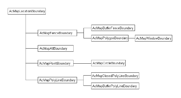
Location Boundaries
There are several types of location boundaries. They are all represented by
descendents of the AcMapLocationBoundary class, as illustrated in the
following diagram.
For more information about query condition types, refer to AutoCAD Map
3D Help. On the Contents tab, click Using AutoCAD Map 3D > Queries >
Defining Queries.
Query Branches
Query branches are trees composed of query conditions, possibly subordinate
query branches, and join operators, which connect the components.
The following diagram illustrates the structure of a simple query branch, in
which a, b, and c are query conditions and AND and OR are join operators.
It expresses the query, a AND b or c.
12 | Chapter 4 Queries
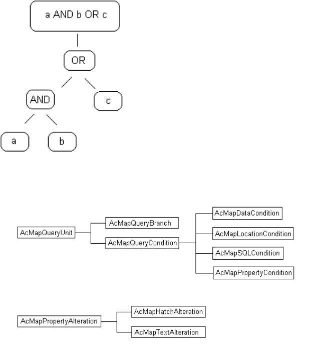
Both query branches and query conditions inherit from the same base class,
as shown in the following diagram.
To build a query
1Create one or more query conditions (also called query units or operands).
2Create one or more query branches.
3Append or insert query conditions onto the branch(es).
4Create the query definition by passing the query branch to the
AcMapQuery::Define function.
Queries Detail | 13
5Create the query as an object in the project using the
AcMapProject::CreateQuery function. This makes the query available to
the application.
6Save the query definition in an external file or query library.
To execute a query
1You may want to set the mode, enable or disable property alteration, or
create a report template for the query.
2Call AcMapQuery::Run to execute the query.
For More Information
For more information about queries, see the UI documentation, AutoCAD
Map 3D Help, and the Map Samples folder of ObjectARX installations.
14 | Chapter 4 Queries
Query Sample
The following sample demonstrates query operations.
5
15
Query Sample Code
16 | Chapter 5 Query Sample
AcMapProject *pProj = NULL;
// Create a new branch object
AcMapQueryBranch *pRootBranch = NULL;
pRootBranch = new AcMapQueryBranch(AcMap::kOperatorOr);
// Create a new property condition
const char *pcValuePC = "Layer1";
AcMapPropertyCondition *pPropertyCondition = NULL;
pPropertyCondition = new AcMapPropertyCondition(
AcMap::kOperatorOr,
AcMap::kLayer,
AcMap::kCondEq,
pcValuePC
);
AcMapSession *pMapSession = NULL;
AcMapQuery *pNewQuery = NULL;
// Get the session object
pMapSession = AcMapGetSession();
if (pMapSession)
{
// Get the currently active project
if (pMapSession->GetProject(pProj) == AcMap::kOk)
{
// Create a new query object
if ( pProj->CreateQuery(
pNewQuery,
Adesk::kFalse) == AcMap::kOk )
{
// Create a new property condition
const char *pcValuePC = "Layer1";
AcMapPropertyCondition *pPropertyCondition = NULL;
pPropertyCondition = new AcMapPropertyCondition(
AcMap::kOperatorOr,
AcMap::kLayer,
AcMap::kCondEq,
pcValuePC
);
// Create a new branch object
AcMapQueryBranch *pBranch = NULL;
pBranch = new AcMapQueryBranch();
// Append the condition to the branch
pBranch->AppendOperand(pPropertyCondition);
// Define the branch in the query
if (pNewQuery->Define(pBranch) == AcMap::kOk)
Query Sample Code | 17
{
// Run the query.
pNewQuery->Run();
}
// Clean up
delete pPropertyCondition;
delete pBranch;
delete pNewQuery;
} // if (pProj->CreateQuery
} // if (pMapSession->GetProject
} // if (pMapSession)
18 | Chapter 5 Query Sample
Property Alteration
Property alteration does not affect corresponding objects in the source drawing or drawings
(unless you deliberately save the queried objects back). The process is controlled by a set of
one or more property alterations, each of which describes how a particular property of queried
objects should be displayed. All the property alterations for a particular query are contained
in the query's property alteration definition.
Property Alteration
You associate a property alteration definition with the query that it affects using
the AcMapQuery::GetPropertyAlteration function. You create a property
alteration and add it to the definition, with the
AcMapPropertyAlterationDefinition::AddAlteration function.
The classes used to create and manipulate property alteration for a query are
AcMapPropertyAlterationDefinition AcMapPropertyAlteration
AcMapTextAlteration AcMapHatchAlteration
The last two classes, which are subclassed from AcMapPropertyAlteration, are
specialized property alterations for adding text labels and hatch patterns to
queried objects.
You can alter properties conditionally, depending on existing values of the
property to be altered or of some other property. To do so, you will also need
to use the following classes:
AcMapRangeLibrary AcMapRangeTable AcMapRangeLine
Property Types
A property alteration's type identifies the property that it alters. The properties
that can be altered are enumerated in AcMap::EAlterationType. When you create
6
19
a property alteration, you set its type by assigning it one of these enumerators.
Note that two of these enumerators, AcMap::kAlterationTextEntity and
AcMap::kAlterationHatch, create the specialized property alteration objects
AcMapTextAlteration and AcMapHatchAlteration, which are subclassed from
AcMapPropertyAlteration. The remaining enumerators simply identify the
different kinds of AcMapPropertyAlteration objects, the simple property
alterations.
AcMapTextAlteration objects in a property alteration definition create text
objects when the query exceutes, which serve as text labels for queried objects.
AcMapHatchAlteration objects create hatch objects, which apply hatch patterns
to closed or closeable queried objects.
The value that the property acquires when the query is run is indicated by
the property alteration's value expression, which you set with the
AcMapPropertyAlteration::SetExpression function. For example, if the property
alteration's type is AcMap::kAlterationColor, you might set its expression to
"Red". If the property alteration's type is AcMap::kAlterationTextEntity, the
property alteration's value expression is the text for the label. If the type is
AcMap::kAlterationHatch, the value expression is a pattern name.
To define a property alteration for a query
1Get the property alteration definition of the query using the
AcMapQuery::GetPropertyAlteration function.
2Create a property alteration and add it to the property alteration definition
using the AcMapPropertyAlterationDefinition::AddPropertyAlteration
function.
3Set the property alteration's expression using the
AcMapPropertyAlteration::SetExpression function.
4Repeat steps 2 and 3 for every property alteration that you want to be
executed by the query.
Applying Property Alteration
When the query is executed, property alteration is applied only if it is defined
and enabled. Use the following AcMapQuery functions to determine whether
property alteration has been defined for a query, whether it has been enabled,
and to enable or disable it as needed.
AcMapQuery::IsPropertyAlterationDefined
AcMapQuery::IsPropertyAlterationEnabled
AcMapQuery::EnablePropertyAlteration
20 | Chapter 6 Property Alteration
Property alteration is defined if the query's property alteration definition
contains at least one property alteration.
Conditional Property Alteration
You can alter properties conditionally, depending on existing values of the
property to be altered or of some other property. For example, you can alter
the colors of queried parcels depending on their assessed value.
A range table is a collection of range lines. A range line consists of a
comparative operator (such as "greater than"), a comparison value (such as
1,000,000), and a return value (such as "Green"), to express a conditional
alteration such as, "If the value is greater than 1,000,000, return green." To
use a range table, pass a range table expression to the property alteration's
SetExpression function. A range table expression has the following format.
where Range is an invariant keyword.
All the range tables available to a project are contained in the project's range
library, an instance of the AcMapRangeLibrary class. A project contains a single
range library.
For More Information
For more information about property alteration and range tables, see the UI
documentation, AutoCAD Map 3D Help, and the Map Samples folder of
ObjectARX installations.
The property alteration feature of AutoCAD Map 3D lets you modify the
appearance of objects queried into the project drawing.
Property Alteration | 21
22
Property Alteration
Sample
This example shows how to create range lines and alterations.
Property Alteration Sample
It also shows how to use them together with a query. It assumes there is a current
project, a project drawing, and at least one active attached drawing with some
drawing objects in it.
7
23
////////////////////////////////////////
// MAIN LOOP
//
// Clears the current query and calls
// DefineRangeLines(), TextAlt(), and
// HatchAlt().
//
////////////////////////////////////////
void doPropAlts()
{
AcMapSession *mapSession = NULL;
mapSession = AcMapGetSession();
if (mapSession)
{
AcMapProject *pProj;
if (mapSession->GetProject(pProj) == Adesk::kTrue)
{
// Get the current Query
AcMapQuery *pCurrentQuery = NULL;
if (pProj->CreateQuery(
pCurrentQuery,
Adesk::kTrue
) == AcMap::kOk)
{
// Before we start, clear the current query
pCurrentQuery->Clear(Adesk::kTrue);
// clean up
delete pCurrentQuery;
}
}
}
// make the calls
DefineRangeLines()
TextAlt()
HatchAlt()
}
////////////////////////////////////
// DefineRangeLines()
//
// Creates two range tables and
// adds them to the range library
//
////////////////////////////////////
24 | Chapter 7 Property Alteration Sample
void DefineRangeLines()
{
AcMapSession *mapSession = NULL;
try
{
Property Alteration Sample | 25
mapSession = AcMapGetSession();
if (mapSession)
{
AcMapProject *pProj;
if (mapSession->GetProject(pProj) == Adesk::kTrue)
{
// Get the range library
AcMapRangeLibrary *pRangeLib = NULL;
if (pProj->GetRangeLibrary(pRangeLib) == Adesk::kTrue)
{
// Add a range table to the library
AcMapRangeTable *pTable = NULL;
const char *pcName = "MyTypeRangeTable";
const char *pcDsc = "Table for types";
if (pRangeLib->AddRangeTable(
pTable,
pcName,
pcDsc
) = AcMap::kOk)
{
// Add range lines that will add text next to
// entites that match the input criteria.
pTable->AddRangeLine(
AcMap::kRangeEq,
"circle",
"CIRCLE");
pTable->AddRangeLine(
AcMap::kRangeEq,
"polygon",
"POLYGON");
pTable->AddRangeLine(
AcMap::kRangeEq,
"polyline",
"PLINE");
pTable->AddRangeLine(
AcMap::kRangeEq,
"line",
"LINE");
pTable->AddRangeLine(
AcMap::kRangeEq,
"lwpolyline",
"LWPOLYLINE");
pTable->AddRangeLine(
26 | Chapter 7 Property Alteration Sample
AcMap::kRangeEq,
"text",
"TEXT");
pTable->AddRangeLine(
AcMap::kRangeOtherwise,
NULL,
"Unknown Type");
}
// clean up
if (NULL != pTable)
{
delete pTable;
pTable = NULL;
}
pcName = "MyHatchRangeTable";
pcDsc = "Table for hatch ranges";
if (pRangeLib->AddRangeTable(
pTable,
pcName,
pcDsc
) == AcMap::kOk)
{
// Add range lines that will add hatch patterns
// to entites that match the input criteria.
pTable->AddRangeLine(
AcMap::kRangeEq,
"circle",
"ANSI31");
pTable->AddRangeLine(
AcMap::kRangeEq,
"polygon",
"CROSS");
pTable->AddRangeLine(
AcMap::kRangeEq,
"polyline",
"ANSI33");
pTable->AddRangeLine(
AcMap::kRangeEq,
"lwpolyline",
"DASH");
pTable->AddRangeLine(
AcMap::kRangeOtherwise,
NULL,
Property Alteration Sample | 27
"SOLID");
}
// clean up
if (NULL != pTable)
{
delete pTable;
pTable = NULL;
}
}
}
}
}
catch(...)
{
// do some error handling
}
}
///////////////////////////////////////////////
// TextAlt()
//
// Creates a Text Alteration and sets the
// expression to the table, MyTypeRangeTable.
// Defines and runs a query with property
// alteration.
//
///////////////////////////////////////////////
void TextAlt()
{
AcMapSession *mapSession = NULL;
try
{
28 | Chapter 7 Property Alteration Sample
mapSession = AcMapGetSession();
if (mapSession)
{
AcMapProject *pProj;
if (mapSession->GetProject(pProj) == Adesk::kTrue)
{
// Get the current Query
AcMapQuery *pCurrentQuery = NULL;
if (pProj->CreateQuery(
pCurrentQuery,
Adesk::kTrue
) == AcMap::kOk)
{
// Get the Property alteration object from the query
AcMapPropertyAlterationDefinition *pPADef = NULL;
if (pCurrentQuery->GetPropertyAlteration(
pPADef
) == AcMap::kOk)
{
AcMapPropertyAlteration *pPropAltObj = NULL;
// Add a Text Alteration
if (pPADef->AddAlteration(
pPropAltObj,
AcMap::kAlterationTextEntity
) == AcMap::kOk)
{
// First we need to cast it
AcMapTextAlteration *pTextAlt = NULL;
pTextAlt = (AcMapTextAlteration*)pPropAltObj;
// set some attributes
pTextAlt->SetColor("Magenta");
pTextAlt->SetJustification("MIDDLE");
pTextAlt->SetRotation("45.0");
pTextAlt->SetHeight("0.5");
pTextAlt->SetExpression(
"(Range .TYPE MyTypeRangeTable)"
);
}
// clean up
if (pPropAltObj)
{
delete pPropAltObj;
pPropAltObj = NULL;
Property Alteration Sample | 29
}
}
// enable property alterations for the query
pCurrentQuery->EnablePropertyAlteration(Adesk::kTrue);
// Create a query branch Entity Type = ALL
AcMapQueryBranch qBranch;
AcMapPropertyCondition propCond;
propCond.SetPropertyType(AcMap::kEntType);
propCond.SetConditionOperator(AcMap::kCondEq);
propCond.SetValue("*") ;
qBranch.AppendOperand(&propCond);
// define the query branch
pCurrentQuery->Define(&qBranch);
// set the query mode to draw
pCurrentQuery->SetMode(AcMap::kQueryDraw);
// run the query
pCurrentQuery->Run();
// clean up
delete pCurrentQuery;
}
}
}
}
catch(...)
{
// do some error handling
}
}
////////////////////////////////////////////////
// HatchAlt()
//
// Creates a Hatch Alteration and sets the
// expression to the table, MyHatchRangeTable.
// Defines and runs a query with property
// alteration.
//
////////////////////////////////////////////////
void HatchAlt()
{
AcMapSession *mapSession = NULL;
try
{
30 | Chapter 7 Property Alteration Sample
mapSession = AcMapGetSession();
if (mapSession)
{
AcMapProject *pProj;
if (mapSession->GetProject(pProj) == Adesk::kTrue)
{
// Get the current Query
AcMapQuery *pCurrentQuery = NULL;
if (pProj->CreateQuery(
pCurrentQuery,
Adesk::kTrue
) == AcMap::kOk)
{
// Get the Property alteration object from the query
AcMapPropertyAlterationDefinition *pPADef = NULL;
if (pCurrentQuery->GetPropertyAlteration(
pPADef
) == AcMap::kOk)
{
AcMapPropertyAlteration *pPropAltObj = NULL;
// Now add a Hatch Alteration
if (pPADef->AddAlteration(
pPropAltObj,
AcMap::kAlterationHatch
) == AcMap::kOk)
{
// First we need to cast it
AcMapHatchAlteration *pHatchAlt = NULL;
pHatchAlt = (AcMapHatchAlteration*)pPropAltObj;
// set some attributes
pHatchAlt->SetScale("2.0");
pHatchAlt->SetColor("Yellow");
pHatchAlt->SetRotation("45.0");
pHatchAlt->SetExpression(
"(Range .TYPE MyHatchRangeTable)"
);
}
// clean up
if (pPropAltObj)
{
delete pPropAltObj;
pPropAltObj = NULL;
}
Property Alteration Sample | 31
}
// enable property alterations for the query
pCurrentQuery->EnablePropertyAlteration(Adesk::kTrue);
// Create a query branch Entity Type = ALL
AcMapQueryBranch qBranch;
AcMapPropertyCondition propCond;
propCond.SetPropertyType(AcMap::kEntType);
propCond.SetConditionOperator(AcMap::kCondEq);
propCond.SetValue("*") ;
qBranch.AppendOperand(&propCond);
// define the query branch
pCurrentQuery->Define(&qBranch);
// set the query mode to draw
pCurrentQuery->SetMode(AcMap::kQueryDraw);
// run the query
pCurrentQuery->Run();
// clean up
delete pCurrentQuery;
}
}
}
}
catch(...)
{
// do some error handling
}
}
// END
32 | Chapter 7 Property Alteration Sample
Designing Queryable
Custom Objects
If you are using AutoCAD ObjectARX to create AcDb custom objects, you must make sure
that they will be retrievable using AutoCAD Map 3D queries.
Designing Queryable Custom Objects Details
Observe the following guidelines:
■Subclass each custom object class from the appropriate ARX parent class, as
detailed below.
■Ensure that each custom object instance in a drawing is added to the Model
Space section of the drawing's Block table.
To support SQL or Data queries, the parent class doesn't matter.
To support location queries, a custom class must derive from AcDbEntity and
overload the methods getGeomExtents, intersectWith, getStretchPoints, and
transformBy.
To support property queries, custom class requirements depend on the properties
to be queried:
Methods to OverloadClass to Derive FromQueryable Property
getAreaAcDbCurveArea
NoneAcDbBlockReferenceBlock Name
8
33
Methods to OverloadClass to Derive FromQueryable Property
Not supported.Elevation
NoneAcDbEntityObject Type
getEndParam getDistAtParamAcDbCurveLength
NoneAcDbTextText Style
NoneAcDbTextText Value
Not supported.Thickness
NoneAcDbEntityColor
NoneAcDbEntityGroup
NoneAcDbEntityLayer
NoneAcDbEntityLinetype
Note Object Type name specified via special MACRO, such as
ACRX_DXF_DEFINE_MEMBERS.
34 | Chapter 8 Designing Queryable Custom Objects
Custom Object Protocol
Extensions
Enables custom objects to participate in AutoCAD Map 3D operations such as Query and Save
Back.
For more information, see
■Custom Object Protocol Extensions in AutoCAD Map 3D ObjectARX Reference Help.
■Custom Object PE sample code, which is located in the Map Samples\QueryPESample
folder of AutoCAD Map 3D ObjectARX installations.
9
35
36
Data Sources
The AutoCAD Map 3D data-sources feature links information from an external database to
objects in a drawing.
Data Sources (page 37)
Other Information Sources
Data Sources Samples (page 38)Data Sources Class (page 38)
Data Sources
The AcMapDataSources class provides the following data-sources functions:
■Constructor/destructor - AcMapDataSources()/~AcMapDataSources()
■Attach data source - AttachDataSource()
■Detach data source - DetachDataSource()
■Detach all data sources - DetachAllDataSources()
■Connect data source - ConnectDataSource()
■Disconnect data source - DisconnectDataSource()
■Disconnect all data sources - DisconnectAllDataSources()
■Count attached data sources - GetAttachedDataSourcesCount()
■Count connected data sources - GetConnectedDataSourcesCount()
■Retrieve connected data sources - GetConnectedDataSources()
■Retrieve disconnected data sources - GetDisconnectedDataSources()
■Retrieve attached data sources - GetAttachedDataSources()
For data-sources source-code samples, see Data Sources Samples (page 38).
10
37
Back to top
Other Information Sources
■For more information about data sources in AutoCAD Map 3D, choose Help > Autodesk
Map Help > Contents tab (or press F1), and then navigate to Using AutoCAD Map
3D (by feature) > External Databases > Attaching and Configuring Data Sources.
■For a data-sources tutorial in AutoCAD Map 3D, choose Help > Tutorials > Contents tab,
and then choose "Working with External Databases".
Back to top
Data Sources Samples
To view code samples of data-sources functions, open the Samples folder in your AutoCAD
Map 3D ObjectARX installation and navigate to Map Samples\DataSource.
Back to top
Data Sources Class
To view the data-sources class, click the following links:
AcMapDataSources Class
Back to top
38 | Chapter 10 Data Sources
Object Data
Object data is non-graphical information about an object in a drawing.
When you want to add such data to a drawing or drawing object, you create an object data
table to store the data.
A single object data table contains records of a similar structure, which is defined by the object
data table's table definition. The individual records in an object data table may be associated
with different drawing objects. The association between the data and the object is at the level
of the individual record, not at the table level.
The classes used to create and manipulate object data tables are
AcMapODColumnDefinition AcMapODContainer AcMapODRecordIterator AcMapODTable
AcMapODTableDefinition AcMapODTableRecord AcMapValue
For More Information
For more information about object data, see the UI documentation, Autodesk Map Help, and
the Map Samples folder of ObjectARX installations.
11
39
40
Object Data Samples
Creating an Object Data Table
The following sample creates an object data table called Zones with two columns,
Residential and Commercial.
To create an object data table
1Include the necessary header files:
#include "StdAfx.h"
#include "StdArx.h"
#include <MapODColumn.h>
#include <MapArxApi.h>
#include <MapODDefinition.h>
#include <MapProj.h>
2Create variables for the session, project, object data container, table, and
columns. For example, create variables for a table with two columns.
AcMapSession *mapApi;
AcMapProject *pProj;
AcMapODContainer *pODCont;
AcMapODTableDefinition *pTabDef = NULL;
AcMapODColumnDefinition *pColDef1 = NULL;
AcMapODColumnDefinition *pColDef2 = NULL;
3Create an AutoCAD Map 3D session and get the top level objects.
mapApi = AcMapGetSession();
mapApi->GetProject(pProj);
pProj->GetODContainer(pODCont);
12
41
4Allocate memory for table and column objects by calling the table and
column constructors with the new operator.
pTabDef = new AcMapODTableDefinition();
pColDef1 = new AcMapODColumnDefinition();
pColDef2 = new AcMapODColumnDefinition();
5For each of the columns, set the column name and description and the
type of data the column stores. Set the default value for the data.
pColDef1->SetName("Residential");
pColDef1->SetDescription("Residential R1-R3");
pColDef1->SetType(AcMap::kCharacter);
pColDef1->SetDefaultValue("R1");
pColDef2 = new AcMapODColumnDefinition();
pColDef2->SetName("Commercial");
pColDef2->SetDescription("Commercial C1-C3");
pColDef2->SetType(AcMap::kCharacter);
pColDef2->SetDefaultValue("C1");
6Add the column definitions to the table definition.
pTabDef->AddColumn(*pColDef1);
pTabDef->AddColumn(*pColDef2);
7Create the object data table. For example, create a table called Zones to
store XData using the following code:
pODCont->CreateODTable("Zones", *pTabDef, "Zoning of King
City",
Adesk::kTrue);
8Release the memory you allocated for the table and columns in step 4
using the delete operator.
if (pColDef2) delete pColDef2;
if (pColDef1) delete pColDef1;
if (pTabDef) delete pTabDef;
Attaching Object Data
The following sample attaches object data to selected objects in a drawing.
It creates a record for each of the objects and adds the data from an existing
table to the records. Open rather than attach the drawing that contains the
objects.
42 | Chapter 12 Object Data Samples
To attach object data
1Include the necessary header files:
#include "StdAfx.h"
#include "StdArx.h"
#include <MapArxApi.h>
#include <MapProj.h>
#include <MapODRecord.h>
#include <MapODTable.h>
2Declare variables.
ads_name ss, ename;
long sslen, sscur;
AcDbObjectId eId;
AcMapSession *mapApi = NULL;
AcMapProject *pProj = NULL;
AcMapODContainer *pODCont = NULL;
AcMapODTable *pODTable = NULL;
3Create an AutoCAD Map 3D session and get the top level objects.
mapApi = AcMapGetSession();
mapApi->GetProject(pProj);
pProj->GetODContainer(pODCont);
4Get the table containing the data to attach.
pODCont->GetODTable(pODTable, "Zones");
5Use ADS functions to prompt user to select the objects to which to attach
the data, and process the selections.
acutPrintf("\nAttach data to which object(s)?");
if (acedSSGet(NULL, NULL, NULL, NULL, ss) != RTNORM) {
acutPrintf("\nNo objects selected.\n");
acedSSFree(ss);
return;
}
6Use an ADS function to determine the number of objects selected in step
5.
acedSSLength(ss, &sslen);
7Loop through the objects selected in step 5, getting the entity name of
the next object, and converting it to an object ID, which you pass to
AcMapODTable::AddRecord. Within the for loop, you create the
AcMapODTableRecord using the new operator, thereby allocating memory
Attaching Object Data | 43
for each record added. Remember to delete each pointer to
AcMapODTableRecord within the loop, as shown here.
for (sscur = 0; sscur < sslen; sscur++)
{
acedSSName(ss, sscur, ename);
acdbGetObjectId(eId, ename);
AcMapODTableRecord *pTabRec = NULL;
pTabRec = new AcMapODTableRecord();
pODTable->AddRecord(*pTabRec, eId);
acutPrintf ("\nOD Record added to object.");
if (pTabRec) delete pTabRec;
}
8Delete the memory allocated by calling AcMapODContainer::GetODTable
in step 4, and free the memory allocated for the selection set in step 5.
delete pODTable;
acedSSFree(ss);
Traversing Object Data
The following sample iterates all of an object's records using
AcMapODContainer::GetObjectODRecordIterator.
You can also iterate only those records that are contained in a specified table
using AcMapODTable::GetObjectODRecordIterator.
To traverse records
1Include the necessary header files:
#include "StdAfx.h"
#include "StdArx.h"
#include <MapArxApi.h>
#include <MapProj.h>
#include <MapODIterator.h>
2Declare variables.
int retCode = FALSE;
ads_name ename;
ads_point spt;
AcDbObjectId eId;
int recQuantity = 0;
AcMapSession *mapApi = NULL;
44 | Chapter 12 Object Data Samples
AcMapProject *pProj = NULL;
AcMapODContainer *pODCont = NULL;
AcMapODRecordIterator *pIter = NULL;
3Create an AutoCAD Map 3D session and get the top level objects.
mapApi = AcMapGetSession();
mapApi->GetProject(pProj);
pProj->GetODContainer(pODCont);
4Use ADS functions to prompt user to select an object, and convert the
entity name of the selected object to an object ID for initializing the
iterator in the next step.
retCode = acedEntSel(NULL, ename, spt);
if (retCode != RTNORM) {
acutPrintf("\nNo object selected.\n");
return;}
acdbGetObjectId(eId, ename);
5Get a record iterator and initialize it for reading.
pODCont->GetObjectODRecordIterator (pIter);
pIter->Init (eId, AcMap::kOpenForRead, Adesk::kFalse);
6Use the record iterator to count records attached to the object. Print the
results.
recQuantity = pIter->CountRecords();
acutPrintf("\nObject has %d records attached.", recQuantity);
7Delete the iterator when you're finished with it.
if (pIter) delete pIter;
Adding or Changing Object Data
The structure for containing data in an object data table is a table record
(AcMapOdTableRecord object).
The actual data in the record is contained in instances of the AcMapValue
class, one value for each field (column) in the record. You read the value of a
record using one form of AcMapODTableRecord::Value, and you add new data
or modify the existing value, using the other form, which is the non-const
override of the function.
Adding or Changing Object Data | 45
The following sample shows how to add new data or modify the current data
in the object records of selected objects. Before performing this procedure,
create a table named Zones. Next, attach data. Data attached to selected objects
consists of two columns: a zoning code column called Code and an Approved
By column.
To add or change object data
1Include the necessary header files:
#include "StdAfx.h"
#include "StdArx.h"
#include <MapODColumn.h>
#include <MapArxApi.h>
#include <MapODDefinition.h>
#include <MapProj.h>
#include <MapODRecord.h>
#include <MapODIterator.h>
2Define a constant for input of the record values and declare variables.
#define USR_STRG_LENGTH 133
int retCode = FALSE;
ads_name ename;
ads_point spt;
char zoneCode [USR_STRG_LENGTH] = "";
char approveCode [USR_STRG_LENGTH] = "";
AcMapSession *mapApi = NULL;
AcMapProject *pProj = NULL;
AcMapODContainer *pODCont = NULL;
AcMapODRecordIterator *pIter = NULL;
AcDbObjectId eId;
AcMapODTableRecord record;
3Create an AutoCAD Map 3D session and get the top level objects.
mapApi = AcMapGetSession();
mapApi->GetProject(pProj);
pProj->GetODContainer(pODCont);
4Use ADS functions to prompt user to select an object, and convert the
entity name of the selected object to an object ID for initializing the
iterator in the next step.
retCode = acedEntSel(NULL, ename, spt);
if (retCode != RTNORM) {
acutPrintf("\nNo object selected.\n");
46 | Chapter 12 Object Data Samples
return;}
acdbGetObjectId(eId, ename);
5Get a record iterator and initialize it for writing. Using the iterator in a
for loop, traverse the records of the object selected in step 4, getting the
table associated with each record.
pODCont->GetObjectODRecordIterator (pIter);
pIter->Init (eId, AcMap::kOpenForWrite, Adesk::kFalse);
for (; pIter->IsDone() == Adesk::kFalse; pIter->Next())
{
pIter->GetRecord (record);
pODCont->GetODTable (pTable, record.ODTableName());
acutPrintf("\n*** OD Table %s.", record.ODTableName());
6Loop through the columns of each record, and print the name of the
column, which in this example is either Code or Approved By.
for (int i = 0; i < record.Count(); i++)
{
AcMapODTableDefinition tableDef = pTable->Definition();
AcMapODColumnDefinition Column;
tableDef.GetColumn(Column, i);
acutPrintf("\n%-15s", Column.Name());
7Print the value at the column of the record and get a pointer, colname,
to the column.
AcMapValue &val = record.Value(i);
acutPrintf(" %s", ((const char *)val));
colname = Column.Name();
8Create an AcMapValue variable and assign the value entered by the user
to it. Then, assign the AcMapValue variable to the value of the record
using the AcMapODTableRecord::Value function. Update the record using
the record iterator.
if(!strcmp(colname, "Code")){
acedGetString(TRUE,"\nNew zoning code:", zoneCode);
AcMapValue v = zoneCode;
record.Value(i) = v;
pIter->UpdateRecord(record);
}
9Using the same paradigm as step 9, get and update the record's Approved
by column.
Adding or Changing Object Data | 47
if(!strcmp(colname, "Approved")){
acedGetString(TRUE,"\nApproved by:", approveCode);
AcMapValue v = approveCode;
record.Value(i) = v;
pIter->UpdateRecord(record);
}
10 End the for loop started in step 7 and delete the pointer to the table
created with AcMapODContainer::GetODTable. End the for loop started
in step 6 and delete the iterator created in step 5.
}//end for
if (pTable) delete pTable;
} //end for
if (pIter) delete pIter;
48 | Chapter 12 Object Data Samples
Coordinate Systems
The AutoCAD Map 3D coordinate-systems functions measure geodetic distance and transform
entities to a specified coordinate system.
Coordinate Systems Details
Coordinate-Systems Functions (page 49)
Other Information Sources
Coordinate Systems Samples (page 50)Coordinate Systems Globals
Coordinate-Systems Functions
The following coordinate-systems functions are available:
■Measure the geodetic distance between two points - ade_projwsgeodistance()
■Transform an entity from the source to the destination coordinate system
- ade_projentityforward()
■Transform an entity from the destination to the source coordinate system
- ade_projentitybackward()
For coordinate-systems source-code samples, see Coordinate Systems Samples
(page 50).
Back to top
13
49
Other Information Sources
■For more information about coordinate systems in AutoCAD Map 3D,
choose Help > Autodesk Map Help > Contents tab (or press F1), and
then navigate to Using AutoCAD Map 3D (by feature) > Coordinate
Systems.
■For a coordinate-systems tutorial in AutoCAD Map 3D, choose Help >
Tutorials > Contents tab, and then choose "Working with Coordinate
Systems".
Back to top
Coordinate Systems Samples
To view code samples of coordinate-systems functions, open the Samples
folder in your AutoCAD Map 3D ObjectARX installation and navigate to Map
Samples\CoordinateSystem.
Back to top
Coordinate Systems Globals
To view the coordinate-systems globals, click the following links:
ade_projwsgeodistance() Global Functionade_projentityforward() Global
Functionade_projentitybackward() Global Function
Back to top
50 | Chapter 13 Coordinate Systems
Converting Coordinates
Converting coordinates from one geo-referenced coordinate system to another.
Converting Coordinates
Any Cartesian coordinate pair you select in a geo-referenced coordinate system
corresponds to a point on the surface of the earth. This fact defines a relation
between the coordinate pairs in one coordinate system and the coordinate pairs
in any other, so long as the point in question actually exists in both systems.
In other words, so long as the coordinate systems have a region of intersection,
and the point in question is in it.
To convert the coordinates of a point from one geo-referenced
coordinate system to another
1Define a "source" coordinate system with ade_projsetsrc.
2Define a "destination" coordinate system with ade_projsetdest.
3Pass a coordinate pair to ade_projptforward.
The function assumes that the coordinate pair you pass to it is a point in
the source system, and it returns the corresponding coordinate pair in the
destination system. If there is no corresponding coordinate pair, it returns
nil.
To convert in the other direction, use ade_projptbackward.
You can specify coordinate triplets, but if you do, the Z value is ignored.
The following sample converts a known position from Latitude Longitude (LL)
to Universal Transverse Mercator (UTM) using ade_projptforward(). If the
conversion is successful, information about the conversion is displayed and the
14
51
UTM coordinate is converted back to Lat Long using ade_projptbackward().
If you don't know the specific coordinate system code, click Select Coordinate
System. In the Select Global Coordinate System dialog box, which is located
under the Map ->Tools->Assign Global Coordinate System menu option. Select
a category, and then select from a list of available coordinate systems. Click
Properties to view the Code value of the selected coordinate system.
52 | Chapter 14 Converting Coordinates
char* pszSourceCoordSys = "LL84";
int resultCode = ade_projsetsrc(pszSourceCoordSys);
char* pszDestCoordSys = "UTM27-15";
resultCode = ade_projsetdest(pszDestCoordSys);
ads_point coordPairToConvert;
coordPairToConvert[0] = -90.4794;
coordPairToConvert[1] = 38.7503;
ads_point convertedCoordPair;
resultCode = ade_projptforward(
coordPairToConvert,
convertedCoordPair);
if (RTNORM == resultCode){
acutPrintf(
"\nThe %s coordinate value of: %.4lf\,%.4lf was successfully
converted"
" to %s yielding the value of: %.4lf\,%.4lf"
, pszSourceCoordSys, coordPairToConvert[0], coordPairToCon
vert[1]
, pszDestCoordSys, convertedCoordPair[0], convertedCoord
Pair[1]);
coordPairToConvert[0] = convertedCoordPair[0];
coordPairToConvert[1] = convertedCoordPair[1];
ads_point convertedBackCoordPair;
resultCode = ade_projptbackward(
coordPairToConvert,
convertedBackCoordPair);
acutPrintf(
"\n\n\nUsing ade_projptbackward(), the %s coordinate value
of: %.4lf\,%.4lf was"
" successfully converted back to %s yielding the value of:
%.4lf\,%.4lf"
, pszDestCoordSys, coordPairToConvert[0], coordPairToConvert[1]
, pszSourceCoordSys, convertedBackCoordPair[0], convertedBack
CoordPair[1]);
}
else {
acutPrintf(
"\nNo coordinate conversion took place.");
}
Converting Coordinates | 53
54
Feature Classification
Use AutoCAD Map 3D's feature-classification feature to create standard objects in drawings.
Feature Classification Detail
Each standard object, called a feature, has a set of user-defined properties and
data, called a feature class. All feature class definitions are stored in a
feature-definition file, or schema. After setting up feature class definitions, you
can use them to create objects with a standard set of properties and data. You
can change property values, or the properties themselves, programmatically.
An organization that creates road maps, for example, might have standard
Primary Road and Secondary Road polyline objects in which the Primary Road
features are created with thick lineweight on the Primary Roads layer, and
Secondary Road features appear with thin lineweight on the Secondary Roads
layer. Each road feature has associated object data, such as speed limit, number
of lanes, and surface type. See also Other Information Sources.
Creating and Managing Schemas (page 56)
Creating and Managing Feature Class Definitions (page 57)
Classifying Entities (page 58)
Managing Attributes of Feature Class Definitions
Managing Properties (page 61)
Using Reactors with Feature Class Definition Events (page 62)
Handling Errors (page 63)
Other Information Sources
Feature Classification Samples (page 63)
15
55
Feature Classification Classes and Namespaces (page 64)
Creating and Managing Schemas
Before you can Creating and Managing Feature Class Definitions (page 57),
you must create a schema and attach it to the current drawing by using
AcMapClassificationManager functions. However, before you create a new
feature-definition file with CreateFeatureDefinitionFile(), use
CanCurrentUserAlterSchema() to check whether the current user has sufficient
privileges to create or change a schema. (Even though you don't check this
first, CreateFeatureDefinitionFile() will catch an insufficient-privileges error.)
Alternatively, rather than creating a new schema, use the currently attached
schema, indicated by GetFeatureDefinitionFileAttached(), or attach an existing
schema with AttachFeatureDefinitionFile(). You can detach a schema explicitly
with DetachCurrentFeatureDefinitionFile().
After creating or modifying a feature class definition in a schema, save the file
withSaveCurrentFeatureDefinitionFile()or save a copy
withSaveCurrentFeatureDefinitionFileAs(). You also can refresh the current
schema withReloadCurrentFeatureDefinitionFile(), but doing so is risky because
it might reload outdated data, depending on the user's actions.
For feature-classification source-code samples, seeFeature Classification Samples
(page 63).
56 | Chapter 15 Feature Classification
// Creates a new feature-definition file.
AcMapObjClass::EErrCode errCode;
const char* pszSchemaFileName = "mySchema.xml";
// Check whether current user can create or change schema.
if (CanCurrentUserAlterSchema())
{
// Create the schema file.
errCode = CreateFeatureDefinitionFile(pszSchemaFileName);
// Handle errors.
switch (errCode)
{
case AcMapObjClass::eNoUserPrivilegeToAlterSchema:
// Insufficient-privileges error.
break;
case AcMapObjClass::eFileAlreadyExists:
// Schema file already exists (and will be attached).
break;
case AcMapObjClass::eFileNameInvalid:
// Invalid file name.
break;
case AcMapObjClass::eFailed:
// Failed for some other reason.
break;
default:
break;
}
// Attach the schema file.
errCode = AttachFeatureDefinitionFile(pszSchemaFileName);
if (errCode == AcMapObjClass::eOk)
{
...
}
}
Back to top
Creating and Managing Feature Class Definitions
After you attach a feature-definition file to the current drawing, you can define
feature classes by using AcMapClassificationManager functions.
Feature Classification Detail | 57
It's prudent to run a few safety checks before you create a feature class
definition. For example, you could do the following:
■Use GetFeatureClassDefinitionCount() to indicate whether any existing feature
classes are defined in the current schema and use GetFeatureClassNames()
to list their names.
■Use IsFeatureClassDefinitionPresent() to determine whether a specific class
definition exists.
Create a feature class definition by using CreateFeatureClassDefinition()
(twoforms). Alternatively, you can use DuplicateFeatureClassDefinition()to copy
an existing feature class definition and thenchange its attributesby using
GetFeatureClassDefinition().
After creating or modifying a feature class definition in a schema, save your
changes
withSaveCurrentFeatureDefinitionFile()orSaveCurrentFeatureDefinitionFileAs().
To rename or delete a feature class definition,
useRenameFeatureClassDefinition()orDeleteFeatureClassDefinition().
For feature-classification source-code samples, seeFeature Classification Samples
(page 63).
Back to top
Classifying Entities
After you create feature class definitions, you can use them to classify the
entities in the current drawing by using AcMapClassificationManager functions.
Use any of the following methods to check entities:
■To avoid redoing or overwriting previous classifications, check which
entities already are classified and with which feature class definitions.
GetClassifiedEntities() (two forms) lists all classified entities in the current
drawing, and GetUnclassifiedEntities() lists the unclassified ones.
■Use GetUndefinedEntities() to list entities that are classified but whose feature
class definitions are not in the attached feature-definition file.
■Use IsClassified() to determine whether a specific entity is classified.
Use any of the following methods to manage classified entities:
■To classify one or more entities, use Classify() (two forms).
58 | Chapter 15 Feature Classification
■To inspect an entity's properties, use GetProperties() (two forms).
■To determine how an entity should be classified (or reclassified), use
GetClassifiedProperties() (two forms).
■To fix out-of-range or missing values of classified properties, use Audit()
(two forms).
■If an entity was classified multiple times by using different
feature-definition files, use GetAllTags() to retrieve all the entity's feature
class names and corresponding feature-definition files.
■To unclassify one or more entities, use Unclassify() (two forms) or
ClearAllTags() (two forms).
For feature-classification source-code samples, seeFeature Classification Samples
(page 63).
Back to top
Managing Attributes of Feature Class Definitions
Use AcMapObjClassDefinition functions to manage the attributes of a feature
class definition stored in the feature-definition file attached to the current
drawing. You can retrieve and (in some cases) set the following attributes:
■Name - GetName()/SetName()
■Description -GetDescription()/SetDescription()
■Icon -GetIconName()/SetIconName()
■Visibility -IsVisibleInWorkspace()/SetVisibleInWorkspace()
■Feature definition file -GetFeatureDefinitionFile()
■Supported entity types - GetSupportedEntityTypes() (two forms)
// Print the name of this feature class definition and the
// pathname of the feature-definition file that it belongs to.
const char* pszFeatureClassDefinitionName = GetName();
const char* pszFeatureDefinitionFile = GetFeatureDefinition
File();
acutPrintf("\nThe feature class definition name is %s", pszFea
tureClassDefinitionName);
acutPrintf("\nThe feature-definition file pathname is %s",
pszFeatureDefinitionFile);
Feature Classification Detail | 59
Use the following functions to determine where a specific feature class exists
in the feature-class
hierarchy:GetDirectBaseClassName(),IsBaseClassOf(),IsBaseClassOnly(),IsDerivedClassOf(),
and IsDirectBaseClassOf().
// Determine whether this feature class definition is a base class
// of the feature class "Parcels".
AcMapObjClass::EErrCode errCode;
bool bBaseClassOf; // Output.
errCode = IsBaseClassOf(&bBaseClassOf, "Parcels");
if (errCode == AcMapObjClass::eOk)
{
if (bBaseClassOf == true)
{
...
}
}
Use GetProperty() or GetProperties() to retrieve a specific property, or all
properties, of a feature class definition. GetProperties() retrieves only properties
that are classified, which you can determine with IsPropertyClassified(). You
can add or delete a property with AddProperty() or DeleteProperty(). To change
a property's attributes, see Managing Properties (page 61).
// Retrieve the Linetype property.
AcMapObjClass::EErrCode errCode;
AcMapObjClassProperty* pProperty = NULL;
AcMapStringArray aStrParentToSubCategoryNames;
aStrParentToSubCategoryNames.Append("General");
const char* pszPropertyName="Linetype";
errCode = GetProperty(pProperty, aStrParentToSubCategoryNames,
pszPropertyName);
if (errCode == AcMapObjClass::eOk)
{
// Process the property.
}
For digitizing data, use SetCreateMethod() (twoforms),GetCreateMethod(), and
GetCreateMethodName()to set or retrieve the AutoCAD entity type that a feature
class definition uses when a digitize process runs.
For feature-classification source-code samples, seeFeature Classification Samples
(page 63).
Back to top
60 | Chapter 15 Feature Classification
Managing Properties
Use AcMapObjClassProperty functions to manage a property for a feature class
definition. You can retrieve and (in some cases) set the following attributes
of a property:
■Name - GetName()
■Direct category - GetCategory()
■Type - GetType()
■Default value -GetDefaultValue()/SetDefaultValue
■Range -GetRange()/SetRange()/IsInRange()
■Visibility -IsVisible()/SetVisible()
■Read-only -IsReadOnly()/SetReadOnly()
■String representation -FromString()/ToString()
For feature-classification source-code samples, seeFeature Classification Samples
(page 63).
// Set the range of the Length property.
AcMapObjClass::EErrCode errCode;
AcMapObjClassProperty* pProperty = NULL;
AcMapStringArray aStrParentToSubCategoryNames;
aStrParentToSubCategoryNames.Append("Geometry");
const char* pszPropertyName = "Length";
errCode = GetProperty(pProperty, aStrParentToSubCategoryNames,
pszPropertyName);
if (errCode == AcMapObjClass::eOk)
{
errCode = pProperty->SetRange("0.0,1.0,2.0,3.0");
if (errCode == AcMapObjClass::eOk)
{
...
}
}
Back to top
Feature Classification Detail | 61
Using Reactors with Feature Class Definition Events
The AcMapObjClassReactorclass provides callback functions that notify an
application immediately of feature class definition events. You use this
mechanism to monitor or control feature class definition operations by
registering reactor instances. Functions are invoked automatically depending
on the operation's type, as described in the following table:
Invoked when aFunction
Feature class definition is createdFeatureClassDefinitionCreated()
Feature class definition is deletedFeatureClassDefinitionDeleted()
Feature class definition is modifiedFeatureClassDefinitionModified()
Feature class definition is renamedFeatureClassDefinitionRenamed()
Feature-definition file is attached to or de-
tached from the current drawing
FeatureDefinitionFileAttached()
Feature-definition file is modified and savedFeatureDefinitionFileModified()
Use AcMapObjClassSystem to register and unregister classification reactors with
AddObjClassReactor() and RemoveObjClassReactor(). To use a reactor, perform
the following steps, as shown in the sample code that follows:
1Derive a custom class from AcMapObjClassReactor.
2Implement events by overriding the virtual functions that you need.
3Create an instance of the custom reactor.
4Register the instance so that it becomes active.
5Write some classification reactor code.
6Remove the reactor from the list and delete it.
For feature-classification source-code samples, seeFeature Classification Samples.
62 | Chapter 15 Feature Classification
// Derive a custom class from AcMapObjClassReactor.
class AcMapObjClassMyReactor : public AcMapObjClassReactor
{
// Override virtual functions for the desired events.
};
// Create an instance of the custom reactor.
AcMapObjClassMyReactor* pMyReactor = new AcMapObjClassMyReactor;
// Register the custom reactor.
AcMapObjClassSystem().AddObjClassReactor(pMyReactor);
// Insert classification reactor code here.
// Remove the reactor and delete it.
AcMapObjClassSystem().RemoveObjClassReactor(pMyReactor);
delete pMyReactor;
Back to top
Handling Errors
Many functions in the various feature-classification classes return an
AcMapObjClass::EErrCode error code. When a particular function returns an
error code, read that function's documentation for function-specific error
conditions rather than relying on only the generic error descriptions in the
AcMapObjClass::EErrCode documentation.
Other Information Sources
■For more information about feature classification in AutoCAD Map 3D,
choose Help > AutoCAD Map 3D Help > Contents tab (or press F1),
and then navigate to Using AutoCAD Map 3D (by feature) > Feature
Classification.
■For a feature-classification tutorial in AutoCAD Map 3D, choose Help >
Tutorials > Contents tab, and then choose "Using Feature Classification".
Back to top
Feature Classification Samples
To view code samples of classification functions, open the Samples folder in
your AutoCAD Map 3D ObjectARX installation and navigate to Map
Samples\Classification.
Back to top
Feature Classification Detail | 63
Feature Classification Classes and Namespaces
To view the feature-classification classes and namespaces, click the following
links:
AcMapClassificationManager Class
AcMapObjClass Namespace
AcMapObjClassDefinition Class
AcMapObjClassProperty Class
AcMapObjClassReactor Class
AcMapObjClassSystem Class
Back to top
64 | Chapter 15 Feature Classification
Object Filters
The AutoCAD Map 3D object-filters feature filters objects (entities) in the current drawing
based on the specified filtering criteria.
Object Filters Detail
Object Filters
The AcDbObjectFilter class is the base class for creating object filters, and provides
the following functions:
■Constructor/destructor - AcDbObjectFilter()/~AcDbObjectFilter()
■Filter objects - FilterObjects()
■Activate object filter - IsActive()/SetActive()
For object-filters source-code samples, see Object Filters Samples.
Basic Filters
The AcDbBasicFilter class (derived from The AcDbObjectFilter) filters objects in
the current drawing based on layer, feature-class, and block criteria, and provides
the following functions:
■Constructor/destructor - AcDbBasicFilter() (two forms)/~AcDbBasicFilter()
■Filter objects - FilterObjects()
■Layer filters:
■Retrieve layers - Layers()
16
65
■Set layers - SetLayers() (two forms)
■Add layers - AddLayers()
■Clears layers - ResetLayers()
■Layer status - LayerStatusMask()/SetLayerStatusMask(). See also ELayerStatus
enum.
■Feature-class filters:
■Retrieve feature classes - FeatureClasses()
■Set feature classes - SetFeatureClasses() (two forms)
■Add feature classes - AddFeatureClasses()
■Clears feature classes - ResetFeatureClasses()
■Block filters:
■Retrieve blocks - Blocks()
■Set blocks - SetBlocks() (two forms)
■Add blocks - AddBlocks()
■Clears blocks - ResetBlocks()
For object-filters source-code samples, see Object Filters Samples.
Back to top
Using Multiple Filters
The AcDbObjectFilterGroup class (derived from The AcDbObjectFilter) filters
objects in the current drawing based the based on the criteria of one or more
listed filters, and provides the following functions:
■Constructor/destructor - AcDbObjectFilterGroup()/~AcDbObjectFilterGroup()
■Add filter - AddObjectFilter()
■Insert filter - InsertObjectFilter()
■Remove filter - RemoveObjectFilter()/RemoveAllObjectFilter()
66 | Chapter 16 Object Filters
■Count filters - ObjectFilterCount()
■Empty test - IsEmpty()
■Retrieve filter - GetObjectFilter()
■Filter objects - FilterObjects()
For object-filters source-code samples, see Object Filters Samples.
Other Information Sources
■For more information about object filters in AutoCAD Map 3D, choose
Help > Autodesk Map Help > Index tab, and then type the keywords
filters and queries to display the related topics.
Object Filters Samples
To view code samples of object-filters functions, open the Samples folder in
your AutoCAD Map 3D ObjectARX installation and navigate to Map
Samples\ObjectFilter.
Object Filters Classes
To view the object-filters classes, click the following links:
AcDbObjectFilter ClassAcDbBasicFilter ClassAcDbObjectFilterGroup Class
Object Filters Detail | 67
68
Import-Export
Use AutoCAD Map 3D's import-export feature to exchange data in industry-standard GIS and
mapping formats.
Import-Export Detail
By importing a map, you can combine data from other mapping or GIS programs
by importing the data into AutoCAD Map 3D. You can import the map objects
themselves, and the data and display options associated with them. In addition,
you can specify an import area to determine which area of the map will be
imported, assign incoming objects to existing feature classes, and automatically
perform a coordinate conversion on the objects as they are imported.
By exporting a map, you can export data to an external file format. You can
export the map objects themselves, and the data associated with them, and
specify that AutoCAD Map 3D performs a coordinate conversion on the objects
automatically as they are exported.
Use profiles to save your import and export settings in a profile to automate
the process of importing and exporting files. You can save and load import
profile files (.ipf) or export profile files (.epf).
The following file formats are supported for both import and export, unless
otherwise indicated:
■ArcView ShapeFile (also called ESRI ShapeFile or ESRI Shape)
■ArcInfo Coverages and E00
■GML (Geography Markup Language) version 2
■GML (Geography Markup Language) version 2, Ordinance Survey of Great
Britain MasterMap (import only)
17
69
■MapInfo MIF/MID
■MapInfo TAB
■MicroStation DGN versions 7 and 8
■SDTS (Spatial Data Transfer Standard) (import only)
■VML (Vector Markup Language) (export only)
■VPF (Vector Product Format) (import only)
See also Other Information Sources.
Importing MapsSetting Import OptionsExporting MapsSetting Export
OptionsUsing Reactors with Export and Import EventsUsing IteratorsHandling
ErrorsOther Information SourcesImport-Export SamplesImport-Export Classes,
Namespaces, and Globals
Importing Maps
To import an file to an AutoCAD Map 3D drawing, perform the following
steps, as shown in the sample code that follows:
1Retrieve the Autodesk Map importer object, an AcMapIEImporter singleton
instance, by calling the global function AcMapImporter().
2Initialize the importer with Init(). (You must call Init() before you call
any other AcMapIEImporter functions.)
Init() requires an AcMapIEFormat name that specifies the format of the
incoming file.
3Optionally, add reactors to the importer.
4Set the import options.
-or-
Use LoadIPF() to load previously saved import settings from a profile (.ipf)
file. (You can save the current import options in a profile file with
SaveIPF().)
5Call Import() to perform the import.
Import results are stored in an AcMapIE::CImportResults struct.
For import-export source-code samples, see Import-Export Samples.
70 | Chapter 17 Import-Export
AcMapIE::ErrCode errCode;
// Retrieve the AutoCAD Map 3D importer object.
AcMapIEImporter* pImporter = AcMapImporter();
// Initialize the importer.
char* pszFormat = "MIF"; // Name of an AcMapIEFormat.
char* pszImpFileName = "C:\\temp\\my_import_file.mif";
errCode = pImporter->Init(pszFormat, pszImpFileName);
if (errCode != AcMapIE::kErr_OK)
{
// Handle the error.
}
// Get an iterator over the layers in the imported file.
AcMapIEInputLayerIterator* pInputLayers;
errCode = pImporter->InputLayerIterator(pInputLayers);
if (errCode != AcMapIE::kErr_OK)
{
// Handle the error.
}
// Iterate over each layer.
for (pInputLayers->Rewind(); !pInputLayers->Done(); pInputLayers-
>Step())
{
AcMapIEInputLayer* pLayer = NULL;
if(pInputLayers->Get(pLayer) == false)
{
// Handle the error.
}
// Import attribute data from the import file to the
// new object-data table in the Autocad Map drawing.
// Insert code to set the table type and table name
// with AcMapIEInputLayer::SetDataMapping()
// and set the feature class name
// with AcMapIEInputLayer::SetFeatureClassName().
// Set column mappings.
AcMapIEColumnIterator* pColumns = pLayer->ColumnIterator();
if(pColumns)
{
for (pColumns->Rewind(); !pColumns->Done(); pColumns->Step())
{
// Insert code to set column data mappings
// with AcMapIEColumn::SetColumnDataMapping()
// and set column feature-class mappings
// with AcMapIEColumn::SetColumnClassMapping().
Import-Export Detail | 71
}
delete pColumns;
}
delete pLayer;
}
delete pInputLayers;
// Perform the import and get the results.
AcMapIE::CImportResults results;
bool bUseProgressDialog = false;
errCode = pImporter->Import(results, bUseProgressDialog);
if(errCode != AcMapIE::kErr_OK)
{
// Handle the error.
}
// Process or log the import results, if desired.
Back to top
Setting Import Options
When importing a drawing into AutoCAD Map 3D, you can set import options
for each incoming layer. AcMapIEImporter::InputLayerIterator() retrieves an
iterator over all imported layers; each layer is an AcMapIEInputLayer instance,
named Name(). Use the following AcMapIEInputLayer functions to set and
retrieve layer-level import options:
■Data-mapping table type and name - DataMapping()/SetDataMapping(). See
also AcMapIE::ImportDataMapping enum.
■Feature class - FeatureClassName()/SetFeatureClassName()
■Import-layer switch - ImportFromInputLayerOn()/SetImportFromInputLayerOn()
■Layer name - LayerName()/SetLayerName(). See also AcMapIE::LayerNameType
enum.
■Point-import mode - PointToBlockMapping()/SetPointToBlockMapping(). See
also AcMapIE::PointMappingType enum.
■Target coordinate system - TargetCoordSys()/SetTargetCoordSys(). See also
OriginalCoordSys().
■Import-attributes switch - UseForBlockAttributes()/SetUseForBlockAttributes()
■Unique keys for imported objects -
UseUniqueKeyField()/SetUseUniqueKeyField()
72 | Chapter 17 Import-Export
On each layer, you can set individual mappings from each incoming column
to a target column in AutoCAD Map 3D. AcMapIEInputLayer::ColumnIterator()
retrieves an iterator over a layer's columns; each column is an AcMapIEColumn
instance, named ColumnName(). You can define two types of column mappings,
provided that you already have set the column's data table and feature class
with AcMapIEInputLayer::SetDataMapping() and
AcMapIEInputLayer::SetFeatureClassName():
■Data mapping - ColumnDataMapping()/SetColumnDataMapping().
■Feature-class mapping - ColumnClassMapping()/SetColumnClassMapping().
Feature-class mappings are not set by default for any column.
You also can use the following AcMapIEImporter functions to set and retrieve
high-level import options:
■Audit classified properties -
AuditClassifiedAfterImport()/SetAuditClassifiedAfterImport()
■Driver options - DriverOptions()/SetDriverOptions()/InvokeDriverOptionsDialog()
■Import polygons as closed polylines -
ImportPolygonsAsClosedPolylines()/SetImportPolygonsAsClosedPolylines()
■Location-window filter -
LocationWindowAndOptions()/SetLocationWindowAndOptions(). See also
AcMapIE::LocationOption enum.
■Reactors - AddReactor()/RemoveReactor(); see Using Reactors with Export and
Import Events
For import-export source-code samples, see Import-Export Samples.
Back to top
Exporting Maps
To export an AutoCAD Map 3D drawing, perform the following steps, as
shown in the sample code that follows:
1Retrieve the Autodesk Map exporter object, an AcMapIEExporter singleton
instance, by calling the global function AcMapExporter().
2Initialize the exporter with Init(). (You must call Init() before you call any
other AcMapIEExporter functions.)
Import-Export Detail | 73
Init() requires an AcMapIEFormat name that specifies the target file format.
You can use FormatName() to retrieve the format name at any time after
initialization.
3Optionally, add reactors to the exporter.
4Set the export options.
-or-
Use LoadEPF() to load previously saved export settings from a profile (.epf)
file. (You can save the current export options in a profile file with
SaveEPF().)
5Call Export() to perform the export.
Export results are stored in an AcMapIE::CExportResults struct.
For import-export source-code samples, see Import-Export Samples.
AcMapIE::ErrCode errCode;
// Retrieve the AutoCAD Map 3D exporter object.
AcMapIEExporter* pExporter = AcMapExporter();
// Initialize the exporter.
char* pszFormat = "MIF"; // Name of an AcMapIEFormat.
char* pszExpFileName = "C:\\temp\\my_export_file.mif";
errCode = pExporter->Init(pszFormat, pszExpFileName);
if (errCode != AcMapIE::kErr_OK)
{
// Handle the error.
}
// Insert code to set filter, data mapping,
// and other <a href="#export_options">export options</a>.
// Perform the export and get the results.
AcMapIE::CExportResults results;
bool bUseProgressDialog = false;
errCode = pExporter->Export(results, bUseProgressDialog);
if (errCode != AcMapIE::kErr_OK)
{
// Handle the error.
}
// Process or log the export results, if desired.
Back to top
74 | Chapter 17 Import-Export
Setting Export Options
Use export options to control which objects in the current drawing are
exported by applying a layer filter, feature-class filter, and selection set.
(CountObjects() counts the number and type of entities to export.) You also
can set storage options, driver options, data mappings, and other options. Use
the following AcMapIEExporter functions to set and retrieve export options:
■Discretization angle - DiscretizationAngle()/SetDiscretizationAngle()
■Driver options - DriverOptions()/SetDriverOptions()/InvokeDriverOptionsDialog()
■Export closed polylines as polygons -
ClosedPolylinesAsPolygons()/SetClosedPolylinesAsPolygons()
■Feature classes to export - FeatureClassFilter()/SetFeatureClassFilter()
■Layers to export - LayerFilter()/SetLayerFilter()
■Mapping layers to DGN levels - LayerLevelMapping()/SetLayerLevelMapping()
■Polygon topology -
ExportFromPolygonTopology()/SetExportFromPolygonTopology()
■Selection set - SelectionSet()/SetSelectionSet() and ExportAll()/SetExportAll()
■Source-column and output-column data mappings -
ExportDataMappings()/SetExportDataMappings()
■Storage options - StorageOpts()/SetStorageOpts(). See also AcMapIE::StorageType
enum and AcMapIE::GeometryType enum.
■Target coordinate system - TargetCoordSys()/SetTargetCoordSys()
■Unique keys for exported objects -
UseUniqueKeyField()/SetUseUniqueKeyField()
■Reactors - AddReactor()/RemoveReactor(); see Using Reactors with Export and
Import Events
For import-export source-code samples, see Import-Export Samples.
Back to top
Using Reactors with Export and Import Events
TheAcMapIEExportReactorandAcMapIEImportReactorreactor classes provide
callback functions that notify an application immediately of export and import
Import-Export Detail | 75
events. You can use these mechanisms to monitor or control export and import
operations by adding reactor instances. Functions are invoked automatically
depending on the stage of the operation, as described in the following tables:
InvokedExport reactor function
If an error occurs during exportRecordError()
After an entity is exportedRecordExported()
Before an entity is exportedRecordReadyForExport()
InvokedImport reactor function
If an error occurs during importRecordError()
After an entity is importedRecordImported()
Before an entity is importedRecordReadyForImport()
You can add or remove export reactors with AcMapIEExporter::AddReactor() or
AcMapIEExporter::RemoveReactor(), and add or remove import reactors with
AcMapIEImporter::AddReactor()or AcMapIEImporter::RemoveReactor(). To use a
reactor, perform the following steps, as shown in the sample code that follows:
1Derive a custom class from AcMapIEExportReactor or
AcMapIEImportReactor.
2Implement events by overriding the virtual functions that you need.
3Create an instance of the custom reactor.
4Add the instance so that it becomes active.
5Write some export or import reactor code.
6Remove the reactor and delete it.
For import-export source-code samples, see Import-Export Samples.
76 | Chapter 17 Import-Export
// Derive a custom class from AcMapIEExportReactor.
class AcMapIEMyExportReactor : public AcMapIEExportReactor
{
// Override virtual functions for the desired export events.
} ;
// Create an instance of the custom reactor.
AcMapIEMyExportReactor* pMyReactor = new AcMapIEMyExportReactor;
// Add the custom reactor.
AcMapIEExporter().AddReactor(pMyReactor);
// Insert export reactor code here.
// Remove the reactor and delete it.
AcMapIEExporter().RemoveReactor(pMyReactor);
delete pMyReactor;
Back to top
Using Iterators
The following table lists the iterator classes, which provide iterators over
collections of objects that import-export functions return or take. The
AcMapIEExpressionTargetIteratorand AcMapIENameValueIteratorclasses allow
you to modify the iterator's underlying collection by adding, updating, and
deleting elements, whereas the other classes iterate over fixed collections. The
global
functionsAcMapExportFormatIterator()andAcMapImportFormatIterator()return
the export-format and import-format iterators, respectively.
Iterates over a collection ofClass
AcMapIEColumn instancesAcMapIEColumnIterator
Expression-target pairsAcMapIEExpressionTargetIterator
AcMapIEFormat instancesAcMapIEFormatIterator
AcMapIEInputLayer instancesAcMapIEInputLayerIterator
Name-value pairsAcMapIENameValueIterator
For import-export source-code samples, see Import-Export Samples.
Back to top
Import-Export Detail | 77
Handling Errors
Many functions in the various import-export classes return an AcMapIE::ErrCode
error code. When a particular function returns an error code, read that
function's documentation for function-specific error conditions rather than
relying on only the generic error descriptions in the AcMapIE::ErrCode
documentation.
Back to top
Other Information Sources
■For more information about importing and exporting maps in AutoCAD
Map 3D, choose Help > AutoCAD Map 3D Help > Contents tab (or
press F1), and then navigate to Using AutoCAD Map 3D (by feature) >
Importing and Exporting Maps.
■For an import-export tutorial in AutoCAD Map 3D, choose Help >
Tutorials > Contents tab, and then choose "Importing and Exporting
Data".
Back to top
Import-Export Samples
To view code samples of import-export functions, open the Samples folder in
your AutoCAD Map 3D ObjectARX installation and navigate to Map
Samples\ImportExport.
Back to top
Import-Export Classes, Namespaces, and Globals
To view the import-export classes, namespaces, and globals, click the following
links:
AcMapIEColumn ClassAcMapIEColumnIterator ClassAcMapIEExporter
ClassAcMapIEExportReactor ClassAcMapIEExpressionTargetIterator
ClassAcMapIEFormat ClassAcMapIEFormatIterator ClassAcMapIEImporter
ClassAcMapIEImportReactor ClassAcMapIEInputLayer
ClassAcMapIEInputLayerIterator ClassAcMapIENameValueIterator ClassAcMapIE
NamespaceAcMapExporter Global FunctionAcMapExportFormatIterator Global
FunctionAcMapImporter Global FunctionAcMapImportFormatIterator Global Function
Back to top
78 | Chapter 17 Import-Export
Oracle Spatial Data
This topic describes the latest implementation of the Oracle Spatial API.
Oracle Spatial Data Detail
Class names in this API begin with "AcMapOSE". Use it for all new development
that involves Oracle Spatial access, or consider using the FDO Enabler API, a
still later implementation, which provides access to Oracle Spatial databases
and other database formats as well.
Although the earlier implementation of the Oracle Spatial API remains in place,
and existing code that is based on it is still valid, it is deprecated. Class names
in the earlier Oracle Spatial API begin with "AcMapOracle". The AcMapOracle
classes are described in the AutoCAD Map 3D ObjectARX Reference, but they
are not discussed in the Developer's Guide.
Managing the connectionManaging reactors (page 80)Exporting data (page 80)
Querying and importing data (page 81)
Oracle and AutoCAD IDs (page 82)
Getting corresponding IDs (page 82)
Getting other information (page 82)
Filtering objects (page 83)
Error processing (page 83)
Other information sources (page 83)
Code samples (page 83)
Classes (page 84)
18
79
Managing the connection
Before you can do anything else, you must get the AcMapOSEConnection
object.
So long as AutoCAD Map 3D is running, there is always an
AcMapOSEConnection object, even if no connection is currently in effect.
The object is instantiated automatically when an AutoCAD Map 3D session
opens, and is destroyed automatically when the session closes.
Because the AcMapOSEConnection object is unique within a session, there
can never be more than one connection in effect at a time. To connect,
disconnect, or change the current connection, you modify this unique object.
You can modify it (or assess its state) either through the the UI or the API. It's
the same object either way.
AcMapOSEConnection class
AcMapOSEGetConnection global function
Connecting to an Oracle Spatial Database (page 85)
Managing reactors
In addition to functions for modifying or assessing its state, the
AcMapOSEConnection object has functions for managing reactors. For
example, to monitor and react to connection events, subclass a custom reactor
from AcMapOSEConnectionReactor, and then add an instance of it to your
application using AcMapOSEConnection::AddConnectionReactor(). Similarly,
you can create and add reactors for import and export events.
AcMapOSEConnection class
AcMapOSEConnectionReactor class
AcMapOSEExportReactor class
AcMapOSEImportReactor class
Connecting to an Oracle Spatial Database (page 85)
Exporting data
To add new records to the Oracle database, or to update records that were
imported and then edited by adding, changing, or deleting data, use an
AcMapOSEExport object. To set export options and specify which features
will be exported, use AcMapOSEExport::Init().
80 | Chapter 18 Oracle Spatial Data
Note that an AcMapOSEExport object has two functions for exporting.
ExportObjects() exports objects listed in an AcDbObjectIdArray.
ExportObjectsAll() exports all objects in the drawing database. Both functions
export only features specified in the vFeaturesNames argument of
AcMapOSEExport::Init(), and both functions are subject to export options
specified by the nOptions argument of AcMapOSEExport::Init(). Option values
are defined in the AcMapOSEExport::EExportOptions enumeration.
To monitor and react to export events, use a custom subclass of
AcMapOSEExportReactor.
Note that, for the sake of performance, the export operation does not process
a set of objects one by one. Rather, it collects the objects with their associated
data in a cache and then bulk-processes them. The complement of
AcMapOSEExportReactor functions reflects this two-step process.
AcMapOSEExport class
AcMapOSEExport::EExportOptions enumeration
AcMapOSEExportReactor class
Exporting to an Oracle Spatial Database (page 89)
Querying and importing data
To import objects from an Oracle database to a project drawing, first use an
AcMapOSEQuery object to specify conditions for the objects to import, and
then use an AcMapOSEImport object for the import itself.
You can initialize the AcMapOSEQuery object with
■The current import query, as defined in the Import dialog box in the user
interface.
To see this dialog, use the MAPOSEREAD command.
■An import query loaded from the Oracle database after saving one there
previously.
■An explicit set of conditions.
After initializing the AcMapOSEQuery object, you can convert its query to
SQL format for viewing purposes.
To monitor and react to import events, use a custom subclass of
AcMapOSEImportReactor.
AcMapOSEQuery class
Oracle Spatial Data Detail | 81
AcMapOSEImport class
AcMapOSEImportReactor class
Importing from an Oracle Spatial Database (page 93)
Oracle and AutoCAD IDs
In Oracle databases, entities have Oracle IDs (OValue). In AutoCAD databases,
they have AutoCAD IDs (AcDbObjectId). When drawing objects are imported
from an Oracle database to a project drawing (AcMapProject object), AutoCAD
Map 3D assigns them AutoCAD IDs, but keeps track their corresponding Oracle
IDs. Note however, that this information is discarded without saving when
the drawing closes, which means that the entire process of updating a set of
Oracle records — importing, editing, exporting — must run from start to finish
on a continuously open drawing.
For information about getting corresponding IDs, click <img height="12"
width="12" border="0" src="graphics/chiclet.gif"> .
Getting corresponding IDs
If you have imported a set of records from an Oracle database, and you need
to know explicitly which record is associated with a given drawing object
(entity), or which entity with a given record, you can use an AcMapOSEObject
object to find out. After intializing such an object with an entity's AutoCAD
ID, you can get its Oracle ID, and vice-versa, provided that the drawing has
remained open since the entity was imported. If the drawing has not remained
open, imported entities lose their imported status, in which case, instead of
the AcMapOSEObject object giving you an Oracle ID in exchange for an entity's
AutoCAD ID, it gives you 0 (an invalid key value), as it does for any entity
that is not an imported one.
For information about Oracle and AutoCAD IDs, click <img height="12"
width="12" border="0" src="graphics/chiclet.gif"> .
Getting other information
You can use AcMapOSEObject functions to get other information about a
queried object besides its AutoCAD or Oracle ID. For example, its EditSet status,
in or out.
AcMapOSEObject class
Getting Corresponding IDs (page 95)
82 | Chapter 18 Oracle Spatial Data
Filtering objects
To filter new objects from a set of drawing objects, use
AcMapOSEProject::FilterNewObjects(). In addition, you can constrain the
result by feature or edit-set status (in or out).
Likewise, to filter queried objects, use AcMapOSEProject::FilterQueriedObjects().
In addition, you can constrain the result by feature or edit-set status (in or
out). Queried objects are delivered in three subsets by edit status: erased,
modified, and unchanged.
AcMapOSEProject class
Filtering Objects (page 99)
Error processing
When an AutoCAD Map 3D operation fails, the error message and error code
are pushed to the error stack (AcMapErrorStack). In the event of an error,
check the stack to discover what went wrong and take appropriate action.
Other information sources
For more information about AutoCAD Map 3D and Oracle Spatial data, refer
to
■User Interface Help for the Polygon and Advanced Oracle Extension to AutoCAD
Map 3D— In the Autodesk Map application, click the question mark icon
in the Polygon And Advanced Oracle Extension toolbar.
Code samples
To view code samples, click links below.
Connecting to an Oracle Spatial Database (page 85)
Exporting to an Oracle Spatial Database (page 89)
Importing from an Oracle Spatial Database (page 93)
Subclassing Custom Reactors (page 88)
Getting Corresponding IDs (page 95)
Filtering Objects (page 99)
Oracle Spatial Data Detail | 83
The following topics describe sample ObjectARX projects. The project folders
are under Map Samples\Oracle Spatial in your AutoCAD Map 3D ObjectARX
installation.
Storing Block Attribute Positions in an Oracle Spatial Database (page 106)
Storing Block Definitions in an Oracle Spatial Database (page 105)
Importing From an Oracle Spatial Database (page 103)
Note The sample projects that are located in Map Samples\Oracle are for the
earlier Oracle Spatial implementation, which is still supported, but is now
deprecated.
Classes
To view Oracle Spatial data classes, click links below.
AcMapOSEConnection
AcMapOSEConnectionReactor
AcMapOSEExport
AcMapOSEExportReactor
AcMapOSEImport
AcMapOSEImportReactor
AcMapOSEObject
AcMapOSEProject
AcMapOSEQuery
84 | Chapter 18 Oracle Spatial Data
Oracle Spatial Samples
The Oracle Spatial samples.
Connecting to an Oracle Spatial DatabaseSubclassing Custom ReactorsExporting to an Oracle
Spatial DatabaseImporting From an Oracle Spatial DatabaseGetting Corresponding IDsFiltering
Objects
Connecting to an Oracle Spatial Database
The following code sample illustrates connecting to an Oracle database and
adding custom reactors.
Custom reactor declarations are in MyMapOracleReactors.h, one of the files
included at the beginning of the sample. The "Subclassing Custom Reactors"
sample shows what such a file would contain.
Managing the connection (page 80)Subclassing Custom Reactors (Sample)Code
samples (page 83)
19
85
#include "StdAfx.h"
#include "StdArx.h"
#include "AdMapOracleConnection.h"
#include "MyMapOracleReactors.h" // Custom reactors
BOOL ConnectToOracle()
{
// Get connection pointer
AcMapOSEConnection *pConnection = AcMapOSEGetConnection();
// Initialize reactors
MyConnectionReactor *pConnectReactor = new MyConnectionReact
or();
MyExportReactor *pExportReactor = new MyExportReactor();
MyImportReactor *pImportReactor = new MyImportReactor();
// Add reactors to connection object
pConnection->AddConnectionReactor(pConnectReactor);
pConnection->AddExportReactor(pExportReactor);
pConnection->AddImportReactor(pImportReactor);
// Make the connection
BOOL bConnect = FALSE;
if(!pConnection->IsConnected())
{
bConnect = pConnection->Connect("Scott", "TestDB", "Scott",
"Tiger", false);
}
else
{
acutPrintf("Already connected to Oracle!");
return FALSE;
}
// Check for valid connection using various diagnostic func
tions
// Check if schema is valid()
if(pConnection->IsSchemaValid())
{
acutPrintf("\nSchema is valid for this connection\n");
}
else
{
acutPrintf("\nSchema is not valid\n");
}
// Get the latest state of the Oracle database if it has been
// changed since the connection was made
86 | Chapter 19 Oracle Spatial Samples
if(pConnection->RefreshSchema())
{
acutPrintf("\nSchema refreshed\n");
}
else
{
acutPrintf("\nError refreshing schema\n"):
}
// Get a list of the feature names in the current schema
std::vector<std::string> vFeatureNames;
if(pConnection->Features(vFeatureNames))
{
acutPrintf("\nGot feature names\n");
}
else
{
acutPrintf("\nError getting feature names\n");
}
// Get the service name
char *pService = 0;
pSerive = new char[80];
strcpy(pService, pConnection->Service());
acutPritnf("\nService is %s\n",pService);
delete [] pService;
// Get the schema name
char *pSchema = 0;
pschema = new char[80];
strcpy(pSchema,pConnection->Schema());
acutPritnf("\nSchema is %s\n",pSchema);
delete [] pSchema;
// Get the user name
char *pUserName = 0;
pUserName = new char[80];
strcpy(pUserName,pConnection->UserName());
acutPritnf("\nUserName is %s\n",pUserName);
delete [] pUserName;
// Break the connection
if(pConnection->Disconnect())
acutPritnf("\nDisconnected from Oracle\n");
else
acutPritnf("\nError disconnecting from Oracle\n");
// Remove reactors from connection interface
pConnection->RemoveConnectionReactor(pConnectReactor);
Connecting to an Oracle Spatial Database | 87
pConnection->RemoveExportReactor(pExportReactor);
pConnection->RemoveImportReactor(pImportReactor);
delete pConnectReactor
delete pExportReactor
delete pImportReactor
}
Subclassing Custom Reactors
The following sample code illustrates subclassing custom reactors from
AcMapOSE[xx]Reactor classes.
Classes and functions are declared, but function definitions, which would be
highly implementation specific, are not shown. This is an example of what
MyMapOracleReactors.h, one of the include files in the "Connecting to an
Oracle Database" sample, would contain.
Managing reactors (page 80)
Connecting to an Oracle Spatial Database (page 85)
Code samples (page 83)
88 | Chapter 19 Oracle Spatial Samples

#include "AdMapOracleReactor.h"
class MyConnectionReactor : public AcMapOSEConnectionReactor
{
public:
MyConnectionReactor();
virtual ~MyConnectionReactor();
virtual void Connected();
virtual void Disconnected();
virtual void BeforeConnect();
virtual void BeforeDisconnect();
};
class MyExportReactor : public AcMapOSEExportReactor
{
public:
MyExportReactor();
virtual ~MyExportReactor();
virtual void BeforeObjectCached(AcDbEntity *);
virtual void ObjectCached(AcDbEntity *,OValue);
virtual void ObjectRejected(AcDbEntity *);
virtual void BeforeObjectsExported(std::vector<OValue> &);
virtual void ObjectsExported(std::vector<OValue> &);
};
class MyImportReactor : public AcMapOSEImportReactor
{
public:
MyImportReactor();
virtual ~MyImportReactor();
virtual void BeforeRecordImport(const ODynaset &);
virtual void RecordImported(const ODynaset &,AcDbEntity *);
virtual void RecordRejected(const ODynaset &);
};
Exporting to an Oracle Spatial Database
The following code sample illustrates exporting spatial data from a project
drawing to an Oracle database.
NOTE The sample assumes an open project drawing containing some objects.
It also assumes that the connection object is actually connected to a database.
Click "Connecting to an Oracle Database" for sample code.
Exporting to an Oracle Spatial Database | 89
#include "StdAfx.h"
#include "StdArx.h"
#include "AdMapOracleConnection.h"
#include "AdMapOracleExport.h"
BOOL ExportToOracle()
{
// Get connection pointer
AcMapOSEConnection *pConnection = AcMapOracleGetConnection();
// Declare export interface
AcMapOSEExport *pExport = new AcMapOSEExport(pConnection);
// Note: Before calling export functions, initialize the
// export interface to specify export options and which
// features to export
// Export Option 1 - Export only new objects and erase
// exported objects from the drawing
// Empty feature vector means export all features in the
// drawing database when you call export functions
std::vector<std::string> vFeatureNames;
// Initialize
if(pExport->Init(vFeatureNames, kRemoveExported))
{
acutPrintf("\nInit() successful\n");
// Export
AcDbDatabase *pDwg;
// Get a valid drawing database reference for *pDwg
// ... (add code here)
if(pExport->ExportObjectsAll(pDwg))
{
acutPrintf("\nExport successful\n");
}
else
{
acutPrintf("\nExport failed\n");
}
}
else
{
acutPrintf("\nExport->Init() failed\n");
}
// Export Option 2 - Export selected features, update
// modified objects in Oracle, and delete erased objects
// from Oracle
vFeatureNames.push_back("Feature1");
Exporting to an Oracle Spatial Database | 91
vFeatureNames.push_back("Feature2");
// Initialize
if(pExport->Init(vFeatureNames,
AcMapOSEExport::kUpdateModified |
AcMapOSEExport::kUpdateErased |
AcMapOSEExport::kRemoveExported))
{
acutPrintf("\nInit() successful\n");
// Export
if(pExport->ExportObjectsAll(pDwg))
{
acutPrintf("\nExport successful\n");
}
else
{
acutPrintf("\nExport failed\n");
}
}
else
{
acutPrintf("\nExport->Init() failed\n");
}
// Export Option 3 - Export a specific set of objects
// Initialize - see initializing code samples above
// Export
AcDbObjectIdArray idArray;
// Populate idArray with a set of objects to export by
// manually selecting or iterating through the drawing
// database
// ... (add code to populate idArray)
if(pExport->ExportObjects(idArray);
{
acutPrintf("\nExport successful\n");
}
else
{
acutPrintf("\nExport failed\n");
}
delete pExport;
}
92 | Chapter 19 Oracle Spatial Samples

Importing from an Oracle Spatial Database
The following sample illustrates importing spatial data from an Oracle database
to a project drawing.
The sample is in two parts. First, it defines a query to specify a condition for
the objects to import, and then it imports them.
NOTE The sample assumes that there is an open project drawing, and that an
import query has been defined already through the Import dialog box in the UI
(use the MAPOSEREAD command). It also assumes that the connection object is
actually connected to a database. Click "Connecting to an Oracle Database" for
sample code.
Connecting to an Oracle Spatial Database (page 85)
Querying and importing data (page 81)
Code samples (page 83)
Importing from an Oracle Spatial Database | 93
#include "StdAfx.h"
#include "StdArx.h"
#include "AdMapOracleConnection.h"
#include "AdMapOracleQuery.h"
#include "AdMapOracleImport.h"
BOOL ImportFromOracle()
{
// Define Query
// Get connection pointer
AcMapOSEConnection *pConnection = AcMapOSEGetConnection();
// Declare query interface
AcmapOSEQuery *pQuery = new AcMapOSEQuery(pConnection);
// Initialize query interface with the current import query
// (defined through the user interface) of an open project
// drawing; in this case, the current project drawing
pQuery->InitWithCurrent(
acdbHostApplicationServices()->workingDatabase());
// Or initialize with a NULL database, which has the same
// effect as the previous call
pQuery->InitWithCurrent();
// Or initialize with specific condition(s)
// Empty vector of features means query all features in the
// Oracle database
std::vector<std::string> vFeatureNames;
pQuery->AddWhereConditionInFeatures(
vFeatureNames,
"AdMapEntityType IS NOT NULL");
// You can clear the query with pQuery->Clear(),
// but not right now; we still need it
// Check the query with ConvertToSql()
char *psql = pQuery->ConvertToSql();
// Save the query to the Oracle database
pQuery->Save("MyQuery");
// Load the saved query into another query object
AcMapOSEQuery *pNewQuery = new AcMapOSEQuery(pConnection);
pNewQuery->Load("MyQuery");
// Compare old and new queries
char *pNewSql = pNewQuery->ConvertToSql();
if(strcmp(pSql,pNewSql) == 0)
acutPrintf("Query Load/Save works!\n");
else
acutPrintf("Query Load/Save failed!\n");
// Import Data
94 | Chapter 19 Oracle Spatial Samples

AcMapOSEImport *pImport = new AcMapOSEImport(pConnection);
// Use query defined above to import data
if(pImport->Import(pQuery))
acutPrintf("\n Import successful\n");
else
acutPrintf("\n Import failed\n");
delete pQuery;
delete pImport;
}
Getting Corresponding IDs
The following sample demonstrates getting an entity's Oracle ID if its AutoCAD
ID is known, and vice versa.
It also demonstrates that round trips with corresponding IDs are reliable —
that if you use an AutoCAD ID to get an Oracle ID, and then use the Oracle
ID to get an AutoCAD ID, the two AutoCAD IDs are the same.
NOTE The sample assumes an open project drawing containing imported entities.
It also assumes that the connection object is actually connected to a database.
Click "Connecting to an Oracle Database" for sample code.
Connecting to an Oracle Spatial Database (page 85)Oracle and AutoCAD IDs
(page 82)Getting corresponding IDs (page 82)Code samples (page 83)
Getting Corresponding IDs | 95
#include "StdAfx.h"
#include "StdArx.h"
#include "AdMapOracleConnection.h"
#include "AdMapOracleIdentification.h"
BOOL Identification()
{
// Get connection pointer
AcMapOSEConnection *pConnection = AcMapOSEGetConnection();
// Declare identification object
AcMapOSEObject *pId = new AcMapOSEObject(pConnection);
AcDbObjectId AcadId;
AcDbEntity *pEntity;
ads_name en;
ads_point pt;
OValue OracleID;
char pBuf[100];
// Get a drawing object (entity) from the user
if(acedEntSel("\nSelect an entity: ", en , pt) == RTNORM)
{
// Get the entity's AutoCAD ID
acdbGetObjectId(AcadId, en);
// Get the entity's handle and print it to the AutoCAD Map
3D text window
if (Acad::eOk == acdbOpenAcDbEntity( pEntity, AcadId,
AcDb::kForRead ))
{
AcadId.handle().getIntoAsciiBuffer(pBuf);
acutPrintf("\nAcad handle sel:%s",pBuf);
pEntity->close();
}
// Initialize identification object with AutoCAD ID
bInit = pId->Init(AcadId);
// Get the entity's corresponding Oracle ID
OracleID = pId->GetOracleID();
// Again initialize identification object, now with Oracle
ID
bInit = pId->Init(OracleID);
// Get the entity's corresponding AutoCAD ID
AcadId = pId->GetAcadID();
// Get the entity's handle and print it to the AutoCAD Map
3D text window,
// and note that it is the same entity as before
96 | Chapter 19 Oracle Spatial Samples
if (Acad::eOk == AcDbOpenAcDbEntity( pEntity, AcadId,
AcDb::kForRead ))
{
AcadId.handle().getIntoAsciiBuffer(pBuf);
acutPrintf("\nAcad handle sel:%s",pBuf);
pEntity->close();
}
// You can get other information about this entity besides
its IDs
// FeatureName()
char *pName;
strcpy(pName,pId->FeatureName());
acutPrintf("\nFeatureName = %s\n",pName);
// IsInEditSet()
if(pId->IsInEditSet())
{
acutPrintf("\nObject is locked\n");
}
else
{
acutPrintf("\nObject is not locked\n");
}
// IsModified()
if(pId->IsModified())
{
acutPrintf("\nObject has been modified\n");
}
else
{
acutPrintf("\nObject has not been modified\n");
}
// IsErased()
if(pId->IsErased())
{
acutPrintf("\nObject has been erased\n");
}
else
{
acutPrintf("\nObject has not been erased\n");
}
// AddToEditSet()
if(pId->AddToEditSet())
{
Getting Corresponding IDs | 97
acutPrintf("\nObject added to EditSet\n");
}
else
{
acutPrintf("\nObject not added to EditSet\n");
}
// RemoveFromEditSet()
if(pId->removeFromEditSet())
{
acutPrintf("\nObject removed from EditSet\n");
}
else
{
acutPrintf("\nObjects not removed from EditSet\n");
}
// Version()
unsigned long ulVersion;
ulVeresion = pId->Version();
// IsUpToDate()
if(pId->IsUpToDate())
{
acutPrintf("\nObject is up to date\n");
}
else
{
acutPrintf("\nObject has been modified since importing
it\n");
}
// WhoHasIt()
unsigned long ulUserId;
std::string strNtuser, strDbUser, strMapUser, strComputer,
strLoginTime;
if(pId->WhoHasIt(
ulUserId,
strNtUser,
strDbUser,
strMapUser,
strComputer,
strLoginTime))
{
98 | Chapter 19 Oracle Spatial Samples
acutPrintf("\nUserId = %ul\n",ulUserId);
acutPrintf("\nNtUser = %s\n",strNtUser.data());
acutPrintf("\nDbuser = %s\n",strDbUser.data());
acutPrintf("\nMapUser = %s\n",strMapUser.data());
acutPrintf("\nComputer = %s\n",strcomputerr.data());
acutPrintf("\nLoginTime = %s\n",strComputer.data());
}
else
{
acutPrintf("\nObject is not locked\n");
}
} // if(acedEntSel("\nSelect an entity: ", en , pt) == RTNORM)
acadSSFree(en);
delete pId;
}
Filtering Objects
The following code sample illustrates filtering queried and new drawing objects,
and adding and removing objects from the EditSet.
Filtering objects (page 83)
Code samples (page 83)
Filtering Objects | 99
#include "StdAfx.h"
#include "StdArx.h"
#include "AdMapOracleConnection.h"
#include "AdMaporacleProject.h"
BOOL FilterProjectObjects()
{
// Get connection pointer
AcMapOSEConnection *pConnection = AcMapOSEGetConnection();
// Declare project interface
AcMapOSEProject *pProject = new AcMapOSEProject(pConnection);
// Initialize project interface with a drawing database
if(pProject->Init(
acdbHostApplicationServices()->workingDatabase()))
{
acutPrintf("\nProject interface initialized\n");
}
else
{
acutPrintf("\nError initializing project interface\n");
}
// Filter queried objects
// Empty vector of features means filter all features in
// the drawing database
std:vector<std:string> vFeatureNames;
// Similarly empty input array of objectIds means filter
// all objects in the drawing database
AcDbObjectIdArray arrInput, arrErased;
AcDbObjectIdArray arrModified, arrUnchanged, arrFilteredOut;
if(pProject->FilterQueriedObjects(
vFeatureNames,
arrInput,
arrErased,
arrModified,
arrUnchanged,
arrFilteredOut,
AcMapOSEProject::kInEditSet | AcMapOSEProject::kNotInEditSet))
{
acutPrintf("\n Input array = %d\n",arrInput.length());
acutPrintf("\n Erased array = %d\n",arrErased.length());
acutPrintf("\n Modified array = %d\n",arrModified.length());
acutPrintf("\n Unchanged array = %d\n",arrUn
changed.length());
100 | Chapter 19 Oracle Spatial Samples
acutPrintf("\n Filter array = %d\n",ar
rFilteredOut.length());
} else {
acutPrintf("\nFilterQueriedObjects() returned false\n");
}
// Filter new objects
// Filter these features
vFeatureNames.push_back("Feature1");
vFeatureNames.push_back("Feature2");
// Empty input array of objectIds means filter all objects
// in the drawing database
AcDbObjectIdArray arrInput, arrNew, arrFilteredOut;
if(pProject->FilterNewObjects(
vFeatureNames,
arrInput,
arrNew,
arrFilteredOut,
AcMapOSEProject::kInEditSet | AcMapOSEProject::kNotInEditSet))
{
acutPrintf("\n Input array = %d\n",arrInput.length());
acutPrintf("\n New array = %d\n",arrErased.length());
acutPrintf("\n Filter array = %d\n",arrFilteredOut.length());
} else {
acutPrintf("\nFilterNewObjects() returned false\n");
}
// Add objects to EditSet
// Populate arrAcadIds with drawing objects by manually
// selecting or iterating through drawing database;
// arrFilteredOut reports objects that could not be
// added to the EditSet
AcDbObjectIdArray arrAcadIds, arrFilteredOut;
// ... (add code to populate arrAcadIds)
if(pProject->AddToEditSet(arrAcadIds, arrFilteredOut))
{
acutPrintf("\nObjects added to EditSet\n");
}
else
{
acutPrintf("\nError adding objects to EditSet\n");
}
// Remove objects from EditSet
// Populate arrAcadIds with drawing objects by manually
// selecting or iterating through drawing database;
Filtering Objects | 101
// arrFilteredOut reports objects that could not be
// removed from the EditSet
AcDbObjectIdArray arrAcadIds, arrFilteredOut;
// ... (add code to populate arrAcadIds)
if(pProject->RemoveFromEditSet(arrAcadIds, arrFilteredOut))
{
acutPrintf("\nObjects removed from EditSet\n");
}
else
{
acutPrintf("\nError removing objects from EditSet\n");
}
delete pProject;
}
102 | Chapter 19 Oracle Spatial Samples
Oracle Spatial Sample
Projects
The Oracle Spatial sample projects.
Importing From an Oracle Spatial Database Storing Block Definitions in an Oracle Spatial
Database Storing Block Attribute Positions in an Oracle Spatial Database
The project folders are in the Map Samples\Oracle Spatial folder in AutoCAD Map 3D
ObjectARX installations.
Note The sample projects that are in Map Samples\Oracle are for the earlier Oracle Spatial
implementation, which is still supported, but is now deprecated.
Importing From an Oracle Spatial Database
Oracle Spatial Data (Overview) Code samples (page 83)
The "Importing From an Oracle Spatial Database" sample is an ObjectARX project
located in the Map Samples\AcMapFlatOrclQuery folder in AutoCAD Map 3D
ObjectARX installations.
Commands Implemented
The project creates an rx module which exposes the following commands.
■ORAAPICONNECT — for connecting to the Oracle database.
■ORAAPIIMPORT — for reviewing, composing, or running queries
■ORAAPIDISCONNECT — for disconnecting.
20
103
Import dialog box
The ORAAPIIMPORT command opens the Import dialog box, which includes
the following elements, among others.
■Condition Samples — A list of conditions read from SqlWhereClauses.txt
on the local machine. Click a condition to view or change it.
■Connect — Click to connect to the Oracle database if not connected
already.
■Features — When connected, a list of features in the current schema. Click
a feature and then click Get Aliases to display a list of aliases and
corresponding names for the feature's tables. See "Table Aliases" below.
Table aliases
To compose a condition for a given feature, you have to specify which table
to use if the feature has more than one, and you have to refer to this table by
its alias. If there is only one table, its alias is "Table0" and specifying it is
optional. The following condition uses a table alias.
Select *
From RIVERS Table0
Where Table.DEPTH > 5;
To get table aliases when there is more than one table for a feature, click Get
Aliases in the Import dialog.
Column types
To write a condition, you may need the type of a given column. To get column
types, click Describe Table in the Import dialog box to get information about
any table in the current schema.
To create a query
1Select one or more features in the Features list box.
2Type a WHERE clause in the edit control below the Condition Samples
list.
The WHERE clause is applied to each of the selected features as it is typed,
without checking to see if it is valid. If the condition is not valid — for
example, if it references a table that does not belong to the feature — the
query fails when it executes.
104 | Chapter 20 Oracle Spatial Sample Projects
3Click View Sql Statement to see the corresponding SQL statement.
If more than one feature is selected, there will be a corresponding number
of SQL statements.
4Click Save to save the query for future use.
5Click Import to run the query and import objects.
To view a saved query
■Click Load.
This action loads a query from the table ADMPIMPORTSETTINGS in the
current schema and displays its SQL statement in a separate dialog box.
You can't execute the query, but you can view it, and you can copy parts
of it to use in other queries.
To run a query
■Click Import.
Note
Keep in mind that the purpose of this application is to instruct. It lacks
extensive error handling. Use it with caution.
Storing Block Definitions in an Oracle Spatial
Database
Oracle Spatial Data (Overview) Code samples (page 83)
The "Storing Blocks" sample is an ObjectARX project located in the Map
Samples\AcMapFlatOrclBlock folder in AutoCAD Map 3D ObjectARX
installations.
Classes highlighted
It highlights the following Oracle Spatial classes.
AcMapOSEExportReactor
The following classes are included also, but their use is less extensive.
AcMapOSEConnection
Storing Block Definitions in an Oracle Spatial Database | 105
Commands implemented
The project creates an rx module which exposes the following commands.
■SAVEBLOCKTOORACLE installs custom export and connection reactors.
These reactors enable storing block definitions in an Oracle database.
■LOADBLOCKSFROMORACLE reads block definitions from an Oracle
database and places them in the table record of the active project drawing.
This command should be executed to set block definitions in place before
importing block references.
■STOPSAVEBLOCKTOORACLE removes the custom reactors that were added
by SAVEBLOCKTOORACLE.
Note
Keep in mind that the purpose of this application is to instruct. Use it with
caution. It lacks extensive error handling, and it may bog down when the
data set is large.
Storing Block Attribute Positions in an Oracle
Spatial Database
Oracle Spatial Data (Overview) Code samples (page 83)
The "Storing Block Attribute Positions" sample is an ObjectARX project located
in Map Samples\AcMapFlatOrclAttrPos in AutoCAD Map 3D ObjectARX
installations.
Classes Highlighted
It highlights the following Oracle Spatial classes.
AcMapOSEConnection AcMapOSEImportReactor AcMapOSEExportReactor
AcMapOSEObject
The following classes are included also, but their use is less extensive.
AcMapOSEImport AcMapOSEExport AcMapOSEQuery
AcMapOSEConnectionReactor
106 | Chapter 20 Oracle Spatial Sample Projects
Commands implemented
The project creates an rx module which lets the user change attribute positions
in a project drawing and preserve these changes in an Oracle database. It
exposes the following commands.
■APEXPORT exports the active project drawing to an Oracle database,
including information about attribute positions.
■APIMPORT imports Oracle Spatial data to the active project drawing,
restoring attributes to their original positions.
Note
The sample assumes that features are already defined completely using our
MAPOSEADMIN command.
Keep in mind that the purpose of this application is to instruct. Use it with
caution. It lacks extensive error handling, and it may bog down when the
data set is large.
Storing Block Attribute Positions in an Oracle Spatial Database | 107
108
Topology
An AutoCAD Map 3D topology is a set of objects and the object data that defines the
relationships between the objects.
Topology Detail
A node topology defines the interrelation of nodes (point objects). Node topologies
often are used in conjunction with other topologies in analysis. Examples of
node topologies include street lights, city-maintained trees, or drill holes for
core samples. A network topology considers the interconnection of links (lines)
forming a linear network. Links can connect nodes. Examples of network
topologies include a street network and a water-distribution application that
traces the flow of water from a pumping station to residences. A polygon topology
defines polygons that represent enclosed areas such as land parcels and census
tracts. A single link defines the common boundary between adjacent areas. A
polygon topology can be used for tax assessment and land planning in which
parcels of land are represented by polygons. Polygon topologies can represent
political boundaries, such as voting districts, city, state, or provincial boundaries,
special districts, and school districts.
With topologies, you can perform spatial analyses such as:
■Trace through network topologies (shortest-path traces, best-route analysis,
and flood traces)
■Find the area within a certain distance of map features (by creating buffers)
■Dissolve and overlay polygon topologies
■Determine conditions of adjacency (what is next to what), containment
(what is enclosed by what), and proximity (how close something is to
something else)
21
109
Topology information is stored as object data on each element that makes up
the topology. This data can be saved as part of the current map, or saved back
to a source drawing. Because topology is definable for a map, identifiers used
to store the topology are unique to the map. Topology in each drawing must
be separate and unique. Autodesk Map does not support topology data that
spans several drawing files (such as tiled maps) unless they are combined in
a project.
You must create centroids for mpolygons and closed polylines before building
a topology with them.
See Creating Centroids.
You must clean drawing objects before building a topology with them.
See Drawing Cleanup.
Creating and Managing Topologies
AcMapTopologyAcMapTopologyManager
■Close a topology - Close()
■Create an instance of topology - AcMapTopology()
■Create a fully specified topology - Create() (two forms). See also
ETopologyType enum and ECreateOptions enum.
Prior to creating a new topology with Create(), call the following functions
to override the default centroid-, edge-, and node-creation settings:
■SetCentroidCreationSettings(). See also AcMapPointCreationSettings class.
■SetEdgeCreationSettings(). See also AcMapEntityCreationSettings class.
■SetNodeCreationSettings(). See also AcMapPointCreationSettings class.
■Delete a topology - Delete()
■Existence test - TopologyExists() (two forms). See also ETopologyScope enum.
■Open a topology in the current drawing - Open(). See also EOpenMode enum.
■Open a topology in the current and source drawings - Open(). See also
EOpenMode enum and EAuditResults enum.
■Update a topology - Refresh()/NeedsRefresh()
For topology source-code samples, see Topology Samples.
110 | Chapter 21 Topology
// Create a topology object, verify it, close it, and destroy
it.
AcMap::EErrCode errCode;
ETopologyType eType = ePoint;
const char* pszTopologyName = "MyNodeTopology";
// For safety, usually add the existence test
// if (AcMapTopologyManager::TopologyExists(pszTopology
Name)){...}
// before creating a new topology.
AcMapTopology* pTopology = new AcMapTopology(pszTopologyName);
// See <a href="#samples">Topology Samples</a> for sample code
// that shows how to populate these arrays.
AcDbObjectIdArray edgeObjIds;
AcDbObjectIdArray nodeObjIds;
AcDbObjectIdArray centroidObjIds;
...
errCode = pTopology->Create(edgeObjIds, nodeObjIds,
centroidObjIds, int(eType));
if(AcMap::kOk == errCode)
{
// Verify the result by closing and reopening the newly created
topology.
pTopology->Close();
pTopology->Open(AcMapTopology::eForRead);
// Another test: Confirm that the topology has the correct
nodes.
AcMapNodePtrArray apNodes;
if (AcMap::kOk == pTopology->GetNodes(apNodes))
{
// Verify the nodes....
apNodes.Empty();
}
else
{
// Cannot get nodes - handle the error.
}
}
else
{
// Cannot create topology - handle the error.
}
// Clean up.
pTopology->Close();
Topology Detail | 111
delete pTopology;
pTopology = NULL;
Managing Topology Properties
AcMapTopologyAcMapTopologyManagerAcMapTopologySource
■Completeness - IsComplete()
■Description - GetDescription()/SetDescription()
■Error-marker styles - GetMarkerStyles(). See also AcMapMarkerStyles class.
■Highlighting - ShowGeometry()
■Loaded or unloaded - IsLoaded()
■Name - GetName()/Rename()
■Scope - GetTopologyScope(). See also ETopologyScope enum.
■Source - GetTopologySource()/GetSource()
■Status - GetStatus(). See also EStatus enum.
■Type -
GetType()/IsFixedType()/IsLinearType()/IsLogicalType()/IsPointType()/IsPolygonType().
See also ETopologyType enum.
Note GetTopologySource() takes topology source information as
AcMapTopologySource instances in the array typedef AcArray<
AcMapTopologySource > AcMapTopologySourceArray.
For topology source-code samples, see Topology Samples.
112 | Chapter 21 Topology
// Rename a topology.
AcMap::EErrCode errCode;
const char* pszTopologyName = "MyTopology";
const char* pszNewTopologyName = "MyRenamedTopology";
errCode = AcMapTopologyManager::Rename(pszTopologyName, pszNew
TopologyName);
if (AcMap::kOk == errCode)
{
// Process the renamed topology.
// Perhaps inspect and change its description.
...
}
else if (AcMap::kErrTopInvalidName == errCode)
{
// Handle the bad topology name. A bad name typically is
// NULL, empty, too long, or has nonalphabetic characters.
}
else if (AcMap::kErrTopNotExist == errCode)
{
// The given topology doesn't exist.
}
else
{
// Handle a different type of error.
}
Adding, Editing, and Deleting Topology Elements
AcMapTopologyAcMapTopoFullEdgeAcMapTopoNodeAcMapTopoPolygon
■Add a curve (linear object) - AddCurveObject()
■Add a point - AddPointObject()
■Add polygon edges - AddPolygons()
■Delete a node - DeleteNode() (two forms)
■Delete a polygon - DeletePolygon() (two forms)
■Delete an edge - DeleteEdge()
■Merge many neighboring polygons - MergePolygons() (two forms)
■Merge two neighboring polygons - MergePolygons() (two forms)
Topology Detail | 113
■Move a node - MoveNode() (two forms)
■Split a polygon - SplitPolygon() (two forms)
For topology source-code samples, see Topology Samples.
// Move a node in a topology.
AcMap::EErrCode errCode;
const char* pszTopologyName = "MyNodeTopology";
AcMapTopology* pTopology = new AcMapTopology(pszTopologyName);
// Open the topology for write.
if (AcMap::kOk == pTopology->Open(AcMapTopology::eForWrite))
{
// Get the node of interest (with object ID = 4, in this case)
// and move it to a new location.
AcMapTopoNode* pNode = NULL;
pTopology->GetNode(pNode, 4);
AcGePoint3d newLocation(39.0, 15.0, 0.0000);
if (AcMap::kOk != pTopology->MoveNode(*pNode, newLocation))
{
// Handle the error.
}
delete pNode;
pTopology->Close();
}
else
{
// Cannot open topology - handle the error.
}
Querying Topologies
AcMapTopologyAcMapTopoFullEdgeAcMapTopoNodeAcMapTopoPolygon
■Specific edge - FindEdge()
■Edge nearest a point - FindEdge()
■Edge, node, or polygon nearest a point - FindTopologyObject(). See also
AcMapTopoElement class.
■Node nearest a point - FindNode()
■Polygon containing a point - FindPolygon()
114 | Chapter 21 Topology
■Polygons neighboring a curve - FindNeighborPolygons(). See also Arrays of
Topology Elements.
For topology source-code samples, see Topology Samples (page 126).
// Find a polygon in a topology.
AcMap::EErrCode errCode;
const char* pszTopologyName = "MyPolygonTopology";
AcMapTopology* pTopology= new AcMapTopology(pszTopologyName);
// Open the topology from the source drawing for read.
if (AcMap::kOk == pTopology->Open(AcMapTopology::eForRead, true,
false, NULL))
{
// Find the polygon containing a specific point.
AcMapTopoPolygon* pPolygon;
AcGePoint3d point(30.0, 12.0, 0.0000);
errCode = pTopology->FindPolygon(pPolygon, point);
if (AcMap::kOk == errCode)
{
// Is this a polygon of interest (with object ID = 184, in
this case)?
if (pPolygon->GetID() == 184)
{
// Process the polygon.
}
}
else
{
// FindPolygon() failed - handle the error.
}
// Clean up.
delete pPolygon;
pPolygon = NULL;
pTopology->Close();
}
else
{
// Failed to open topology - handle the error.
}
Topology Detail | 115
Retrieving Topology Elements
AcMapTopologyAcMapTopoFullEdgeAcMapTopoHalfEdgeAcMapTopoNodeAcMapTopoPolygon
■All AutoCAD entities - GetEntityIds()
■All full edges - GetFullEdges(). See also Arrays of Topology Elements.
■All nodes - GetNodes(). See also Arrays of Topology Elements.
■All polygons - GetPolygons(). See also Arrays of Topology Elements.
■Specific AutoCAD entity - GetEntityId()
■Specific full edge - GetFullEdge()
■Specific half edge - GetBackwardEdge()/GetForwardEdge()
■Specific node - GetNode()
■Specific polygon - GetPolygon()
For topology source-code samples, see Topology Samples.
116 | Chapter 21 Topology
// Get the nodes of a topology.
AcMap::EErrCode errCode;
const char* pszTopologyName = "MyNodeTopology";
AcMapTopology* pTopology = new AcMapTopology(pszTopologyName);
AcMapNodePtrArray apNodes;
// Open the topology for read.
if (AcMap::kOk != pTopology->Open(AcMapTopology::eForRead, true,
false, NULL))
{
// Failed to open topology - handle the error.
}
if (Acad::eOk == pTopology->GetNodes(apNodes))
{
// Process each node.
for (int i = 0; i < apNodes.length(); i++)
{
// Get the node location.
AcGePoint3d point;
errCode = apNodes[i]->GetLocation(point);
if(Acad::eOk == errCode)
{
// Process the node.
}
}
}
else
{
// GetNodes() failed - handle the error.
}
// Clean up.
apNodes.Empty();
pTopology->Close();
Back to top
Managing Topology Elements
AcMapTopology
■Full edges - AcMapTopoFullEdge instances (derived from AcMapTopoElement)
■Associated AutoCAD entity - GetEntity()
■Associated polygon - GetPolygon(). See also AcMapTopoPolygon class.
Topology Detail | 117
■Associated ring - GetRing(). See also AcMapTopoRing class.
■Associated topology - GetTopology(). See also AcMapTopology class.
■Coincident or nearby point - IsOnThisObject()
■Edge direction - GetDirection()/SetDirection(). See also EDirection enum.
■Edge length - GetLength()
■Edge resistance - GetResistance()/SetResistance()
■Next edge - GetNextEdge()
■Next node - GetNextNode()
■Traversing half edge - GetHalfEdge()
■Unique identifier - GetID()
■Half edges - AcMapTopoHalfEdge instances
■Associated polygon - GetPolygon(). See also AcMapTopoPolygon class.
■Associated ring - GetRing(). See also AcMapTopoRing class.
■Associated topology - GetTopology(). See also AcMapTopology class.
■Containing full edge - GetFullEdge()
■Edge resistance - GetResistance()/SetResistance()
■Next edge - GetNextEdge()
■Next/previous node - GetNextNode()/GetPreviousNode()
■Nodes - AcMapTopoNode instances (derived from AcMapTopoElement)
■Associated AutoCAD entity - GetEntity()
■Associated topology - GetTopology(). See also AcMapTopology class.
■Coincident or nearby point - IsOnThisObject()
■Edges - GetEdges(). See also AcMapTopoHalfEdge class and Arrays of Topology
Elements.
■Next edge - GetNextEdge() (two forms). See also AcMapTopoFullEdge and
AcMapTopoHalfEdge classes.
118 | Chapter 21 Topology
■Node location - GetLocation()/SetLocation()
■Node mobility - IsMoveable()/SetIsMoveable()
■Node resistance - GetResistance()/SetResistance()
■Unique identifier - GetID()
■Polygons - AcMapTopoPolygon instances (derived from AcMapTopoElement)
■Associated AutoCAD entity - GetEntity()
■Associated topology - GetTopology(). See also AcMapTopology class.
■Coincident or nearby point - IsOnThisObject()
■Hierarchical parent/children polygons - GetHierParent()/GetHierChildren()
■Multi-polygon parent - GetParent()
■Polygon area - GetArea()
■Polygon boundary - GetBoundary(). See also Arrays of Topology Elements.
■Polygon centroid - GetCentroid()
■Polygon perimeter - GetPerimeter()
■Traversal to neighboring polygon - Traverse()
■Unique identifier - GetID()
■Rings - AcMapTopoRing instances
■Constituent edges - GetEdges(). See also AcMapTopoHalfEdge class and Arrays
of Topology Elements.
■First edge - GetStartEdge(). See also AcMapTopoHalfEdge class.
■Outer polygon boundary - IsExterior(). See also
AcMapTopoPolygon::GetBoundary().
■Ring area - GetArea()
■Ring length - GetLength()
For topology source-code samples, see Topology Samples.
Topology Detail | 119
// Get a specific polygon from a topology and print
// statistics for its rings.
AcMap::EErrCode errCode;
char* pszTopologyName = "MyTopology";
AcMapTopology* pMapTopology = NULL;
// Open the topology for read.
if (AcMapTopologyManager::TopologyExists(pszTopologyName))
{
pMapTopology = new AcMapTopology(pszTopologyName);
if(AcMap::kOk != pMapTopology->Open(AcMapTopology::eForRead))
{
// Cannot open topology - handle the error.
}
}
// Get a polygon of interest (with object ID = 10, in this case)
// and retrieve its rings with GetBoundary().
AcMapTopoPolygon* pPolygon = NULL;
if (AcMap::kOk == pTopology->GetPolygon(pPolygon, 10))
{
// Get the polygon's rings.
AcMapRingPtrArray apRings;
errCode = pPolygon->GetBoundary(apRings);
if (AcMap::kOk == errCode)
{
// Get statistics for each ring.
int nRings = apRings.length(); // Number of rings.
for (int nRingIndex = 0; nRingIndex < nRings; nRingIndex++)
{
AcMapTopoRing* pRing = apRings[nRingIndex];
// Is ring exterior or interior?.
char* pszExtOrInt = pRing->IsExterior() ? "exterior" :
"interior";
// Print the rings' area and length.
acutPrintf("\n#%d is %10s, Area: %-0.4lf Length: %-0.4lf",
(nRingIndex + 1), pszExtOrInt, pRing->GetArea(), pRing-
>GetLength());
}
apRings.Empty(); // Free the array of rings.
}
else
{
// Cannot get the polygon's boundary - handle the error.
}
120 | Chapter 21 Topology
}
else
{
// Cannot get the specified polygon - handle the error.
}
// Clean up.
delete pPolygon;
pPolygon = NULL;
pMapTopology->Close();
Back to top
<a id="analyzing">Analyzing Topologies
■Shortest-path trace - A shortest-path trace uses a network topology to
calculate the shortest path between two points or determine the optimal
route based on values of direction and resistance. In a street network, for
example, you can find the shortest path between a fire station and a school.
Use TraceLeastCostPath() to calculate a shortest-path trace and an
AcMapTraceParameters instance to set trace parameters.
■Best-route trace - A best-route trace uses a network topology to calculate
the best route from a starting point to an end point, with one or more
intermediate points. AutoCAD Map 3D determines the optimal route based
on values of direction and resistance. In a street network, for example, you
can find the best route to travel when visiting several customer sites from
a hotel. Use TraceBestPath() to calculate a best-route trace and an
AcMapTraceParameters instance to set trace parameters.
■Flood trace - A network flood trace traces out from a point in all directions,
given the point where the network starts and the maximum distance that
the network can traverse. A flood trace determines how many links and
nodes can be traveled before the accumulated resistance exceeds the
specified maximum resistance. You can find all restaurants within a
10-minute walk of a hotel, for example, or check the integrity of a network
topology (if some links are not flooded, the topology is incomplete). Use
TraceFlood() to calculate a flood trace and an AcMapFloodParameters instance
to set trace parameters.
■Buffering a topology - Buffer analysis, or buffering, identifies objects within
a specified offset of elements in node, network, and polygon topologies.
A buffer is a zone that is drawn around a topology. You can specify a buffer
on either side of a river to show the extent of a flood plain, for example.
Use Buffer() to create a new topology with a buffer setting.
Topology Detail | 121
■Dissolving a composite topology - If a topology contains many smaller
polygons, you can create a new topology by combining polygons that
share the same data value in a specified field, called the dissolve field,
which can be an object-data field or a column in a linked external database.
Use Dissolve() to dissolve a topology.
■Overlaying topologies - Overlay analysis lets you overlay topologies that
are loaded into the current drawing. The three types of overlay analysis
are nodes with polygons, networks with polygons, and polygons with
polygons. When you overlay two topologies, you choose the method in
which the two selected topologies interact. In some cases, the result varies
according to which topology is the source and which is the overlay. You
have the following overlay options:
■Clip() - A clip operation uses the overlay polygon topology as a boundary.
The parts of the source polygons outside the overlay polygons are clipped
and discarded. You can use this option to show polygons within a boundary
polygon, such as a city or state boundary.
■Erase() - An erase operation uses the overlay polygon topology like a mask
and erases everything in the source polygon topology that is covered by
the overlay topology.
■Identity() - An identity operation works like Union() on the source topology
and like Intersect() on the overlay topology. Use Identity() to combine
nodes, links, or polygons with polygons and keep all the input geometry.
Identity() creates one topology with one link where the link is crossed by
the overlay topology.
■Intersect() - An intersect operation combines topologies and keeps only the
common geometry. Intersect() acts like the Boolean AND operation. The
results are the same whichever topology is chosen as the first or second.
Object data is combined for the two operations.
■Paste() - A paste operation pastes the overlay polygon topology on top of
the source polygons. The source polygons not covered by the overlay
remain. Paste() can be used with only polygons.
■Union() - A union operation combines polygons with polygons and keeps
all geometry. Union() acts like the Boolean OR operation and can be used
with only polygons. You can combine parcels with soils information for
property assessment, for example. Use Union() to maintain both sets of
geometry together and pull them apart as needed.
122 | Chapter 21 Topology
■The overlay functions all take source and overlay data as
AcMapTopoOverlayData instances in the array typedef AcArray<
AcMapTopoOverlayData > AcMapOverlayDataArray.
Note Before creating new topologies by buffering or overlaying existing
topologies, you can call SetCentroidCreationSettings(), SetEdgeCreationSettings(),
and SetNodeCreationSettings() to override the default topology-creation values.
For topology source-code samples, see Topology Samples.
Topology Detail | 123
// Two topologies are needed: source and overlay.
const char* pszSourceTopologyName = "MyNodeTopology";
AcMapTopology* pSourceTopology = new AcMapTopology(pszSourceTo
pologyName);
const char* pszOverlayTopologyName = "MyPolygonTopology";
AcMapTopology* pOverlayTopology = new AcMapTopology(pszOverlayTo
pologyName);
AcMap::EErrCode errCode;
// Open both source and overlay topologies for read.
if(AcMap::kOk == pSourceTopology->Open(AcMapTopology::eForRead))
{
if(AcMap::kOk == pOverlayTopology->Open(AcMapTopology::eFor
Read))
{
// Create the intersection of the source and overlay topolo
gies.
errCode = pSourceTopology->Intersect(pOverlayTopology,
"OutputTopo", "Intersect", NULL, NULL, NULL);
if(AcMap::kOk == errCode)
{
// Process the topology intersection.
}
else
{
// Cannot create topology intersection - handle the error.
}
pOverlayTopology->Close();
}
else
{
// Cannot open overlay topology - handle the error.
}
pSourceTopology->Close();
}
else
{
// Cannot open source topology - handle the error.
}
Using Iterators
AcMapTopoIteratorAcMapTopology
■Count the number of topologies - Count()
124 | Chapter 21 Topology
■Last-element flag - IsDone()
■Move to first/next element - First()/Next()
■Current topology - GetTopology()
■Current topology's name - GetName()
■Current topology's description - GetDescription()
■Current topology's type - GetType()
For topology source-code samples, see Topology Samples.
AcMap::EErrCode errCode;
// Initialize the iterator.
AcMapTopoIterator* pIterator = new AcMapTopoIterator;
AcMapTopology* pTopology = NULL;
// Iterate through the topology objects.
pIterator->First();
while (!pIterator->IsDone())
{
pIterator->GetTopology(pTopology);
// Process the topology...
errCode = pIterator->Next();
}
delete pIterator;
delete pTopology;
// To iterate with a for-loop:
// for (pIterator.First(); !pIterator.IsDone(); pIterator.Next())
{...}
Arrays of Topology Elements
AcMapTopoElementPtrArray
Holds pointers toArray class
AcMapTopoFullEdge instancesAcMapFullEdgePtrArray
AcMapTopoHalfEdge instancesAcMapHalfEdgePtrArray
AcMapTopoNode instancesAcMapNodePtrArray
Topology Detail | 125
Holds pointers toArray class
AcMapTopoElement instancesAcMapObjectPtrArray
AcMapTopoPolygon instancesAcMapPolygonPtrArray
AcMapTopoRing instancesAcMapRingPtrArray
For topology source-code samples, see Topology Samples.
Handling Errors
Many functions in the various topology classes return an AcMap::EErrCode
error code. When a particular function returns an error code, read that
function's documentation for function-specific error conditions rather than
relying on only the generic error descriptions in the AcMap::EErrCode
documentation.
Other Information Sources
■For more information about topology in AutoCAD Map 3D, choose Help
> AutoCAD Map 3D Help > Contents tab (or press F1), and then
navigate to Using AutoCAD Map 3D (by feature) > Topology (Spatial
Analysis).
■For a topology tutorial in AutoCAD Map 3D, choose Help > Tutorials
> Contents tab, and then choose "Using Topology and Spatial Analysis".
■For information about object data in AutoCAD Map 3D, choose Help >
AutoCAD Map 3D Help > Contents tab (or press F1), and then navigate
to Using AutoCAD Map 3D (by feature) > Object Data.
Topology Samples
To view code samples of topology functions, open the Samples folder in your
AutoCAD Map 3D ObjectARX installation and navigate to Map
Samples\Topology.
Topology Classes, Namespaces, and Globals
To view the topology classes, namespaces, and globals, click the following
links:
126 | Chapter 21 Topology
AcMapTopology Class
AcMapTopoElement Class
AcMapTopoFullEdge Class
AcMapTopoHalfEdge Class
AcMapTopoNode Class
AcMapTopoPolygon Class
AcMapTopoRing Class
AcMapTopoIterator
AcMapTopologySource Class
AcMapTopoOverlayData Class
AcMapEntityCreationSettings Class
AcMapPointCreationSettings Class
AcMapFloodParameters Class
AcMapTraceParameters Class
AcMapNetAnalysisParameters Class
AcMapMarkerStyles Class
AcMapTopoElementPtrArray Template Class
AcMapObjectPtrArray Class
AcMapFullEdgePtrArray Class
AcMapHalfEdgePtrArray Class
AcMapNodePtrArray Class
AcMapPolygonPtrArray Class
AcMapRingPtrArray Class
AcMapTopologyManager Namespace
AcMapObjectDataField Global Struct
AcMapObjectDataTable Global Struct
ETopologyMarkType Global Enum
ETopologyType Global Enum
Topology Detail | 127
128
Centroids
Creating centroids moves attached data from the perimeters of mpolygons and closed polylines
to their centroids so that the data is not lost when topologies are created.
Creating Centroids
You must create centroids for mpolygons and closed polylines before building
a topology with them.
A closed polyline is a polygon produced by the POLYGON command.
Creating Centroids (page 129)
Other Information Sources
Creating Centroids Samples (page 130)Creating Centroids Namespace (page 130)
Creating Centroids
Use the CreateCentroids() (twoforms) functions in the AcMapUtilities namespace
to create centroids.
For centroid-creation source-code samples, see Creating Centroids Samples (page
130).
Back to top
Other Information Sources
■For more information about creating centroids in AutoCAD Map 3D, choose
Help > Autodesk Map Help > Contents tab (or press F1), and then
navigate to Using AutoCAD Map 3D (by feature) > Topology (Spatial
Analysis) > Editing Topologies > Creating Centroids for Polygons.
22
129
Back to top
Creating Centroids Samples
To view code samples of centroid-creation functions, open the Samples folder
in your AutoCAD Map 3D ObjectARX installation and navigate to Map
Samples\CreateCentroid.
Back to top
Creating Centroids Namespace
To view the centroid-creation namespace, click the following link:
AcMapUtilities Namespace
Back to top
130 | Chapter 22 Centroids
Drawing Cleanup
You must clean drawing objects before building a topology with them.
Drawing Cleanup Details
Let's look at this in two phases, preparing the cleanup model, which ends with
a call to tpm_cleaninit, and executing the cleanup, which begins with a call to
tpm_cleanstart.
To prepare the cleanup model
1Allocate memory for the cleanup model. Use tpm_cleanalloc.
ade_id cleanupModelId = tpm_cleanalloc();
2Allocate memory for cleanup variables, which specify properties for the
cleanup process. The variables are initialized to their default values. Use
tpm_varalloc.
ade_id cleanupVarId = tpm_varalloc();
If you will be specifying an explicit list of cleanup actions (you create and
manage this list with calls to tpm_cleanactionlistins and related functions),
also allocate memory for cleanup action variables, which specify properties
for individual actions. Again use tpm_varalloc.
ade_id cleanupActionVarId = tpm_varalloc();
3Get a selection set of objects to be cleaned (the include set).
ads_name ssObjsForCleanup;
acutPrintf("\nSelect the objects to perform cleanup on.");
acedSSGet(NULL, NULL, NULL, NULL, ssObjsForCleanup);
23
131
Or create one.
struct resbuf* pFilteredEntitySelectionRb = acutBuildList(
RTDXF0, "LWPOLYLINE",
8, "UtilityNetwork-Electric",
0);
ads_name ssObjsForCleanup;
acedSSGet("X", NULL, NULL, pFilteredEntitySelectionRb,
ssObjsForCleanup);
acutRelRb(pFilteredEntitySelectionRb);
You can also get a selection set of objects to be anchored (the anchor set).
Anchored objects are not repositioned by the cleanup process, but remain
fixed while others are repositioned around them.
ads_name ssObjsToAnchor;
acutPrintf("\nSelect the objects to serve as an anchor.");
acedSSGet(NULL, NULL, NULL, NULL, ssObjsToAnchor);
The acedSSGet function prompts the user to select objects and returns a
selection set. This function can also be used with a resbuf to filter selected
objects. Make sure to release selection sets when finished with them,
using acedSSFree()
4Set cleanup variables using tpm_varset with the clean_var_id that you
allocated in step 2. A few of these variables specify cleanup actions, but
most of them specify how cleanup actions will be performed.
// Set the cleanup variable "LINK_ERROR" for break crossing.
char* pszConfigVarName = "LINK_ERROR";
struct resbuf* pLinkErrorVarValRb = acutBuildList(
RTSHORT, 2,
0);
int resultCode = tpm_varset(
cleanupVarId,
pszConfigVarName,
pLinkErrorVarValRb);
acutRelRb(pLinkErrorVarValRb);
// Set the cleanup variable "INCLUDEOBJS_AUTOSELECT".
// Must be included with a filtered selection set.
pszConfigVarName = "INCLUDEOBJS_AUTOSELECT";
struct resbuf* pIncludeObjsVarValRb = acutBuildList(
RTSHORT, 0,
0);
resultCode = tpm_varset(
cleanupVarId,
pszConfigVarName,
132 | Chapter 23 Drawing Cleanup
pIncludeObjsVarValRb);
acutRelRb(pIncludeObjsVarValRb);
// Set the cleanup variable "INCLUDEOBJS_LAYERS".
// Must be included with a filtered selection set.
pszConfigVarName = "INCLUDEOBJS_LAYERS";
struct resbuf* pIncludeObjsLyrVarValRb = acutBuildList(
RTSTR, "UtilityNetwork-Electric",
0);
resultCode = tpm_varset(
cleanupVarId,
pszConfigVarName,
pIncludeObjsLyrVarValRb);
acutRelRb(pIncludeObjsLyrVarValRb);
Before setting cleanup variables, you can load a cleanup profile if you
saved one previously, and in that way set many variables at once. Use
tpm_cleanprofileload.
resultCode = tpm_cleanprofileload(
cleanupVarId,
"C:\\profile.dpf");
If you specify an explicit list of cleanup actions, note that those will be
the only actions performed. Cleanup actions specified by the variables
NODE_ERROR, LINK_ERROR, and GENERALIZE will be ignored, as well
as any setting specific to them only, such as CORRIDOR's, which defines
the tolerance for GENERALIZE.
Using an action list is the best way to specify cleanup actions, because
you can specify the order in which they execute, and you can include
the same action more than once. Using variables to specify cleanup actions
is an older technique, which is still supported for the sake of older scripts,
but it is deprecated from AutoCAD Map 3D 6 onward.
Note When you insert the Simplify Objects action (clean group type 128),
it is always listed first, and you cannot insert it more than once.
With an explicit list of cleanup actions, note that certain individual
actions can have individual tolerance settings (and in some cases, other
settings also). See Cleanup Action Variables. When you are about to insert
an action into the action list, you can use tpm_varset with the
action_var_id that you allocated in step 2 to set variables for this action
before calling tpm_cleanactionlistins. You can continually reset and reuse
the same set of cleanup action variables with each action that you insert.
// Set CLEAN_TOL cleanup variable for simplify objects,(weed
ing).
pszConfigVarName = "CLEAN_TOL";
Drawing Cleanup Details | 133
struct resbuf* pCleanTolVarValRb = acutBuildList(
RTREAL, 2.0,
0);
resultCode = tpm_varset(
cleanupActionVarId,
pszConfigVarName,
pCleanTolVarValRb);
acutRelRb(pCleanTolVarValRb);
Insert a cleanup action for simplify objects by specifying the cleanup
variables id (real) returned by tpm_cleanalloc(), the index at which the
item will be inserted into the list, the clean group type code, (see
tpm_cleangrouptype for a list of types) and the cleanup action variable id
(real) returned by tpm_varalloc().
resultCode = tpm_cleanactionlistins(
cleanupVarId,
0,
128,
cleanupActionVarId);
Insert an additional cleanup action for break crossing objects. The index
position of -1 is for the last position.
resultCode = tpm_cleanactionlistins(
cleanupVarId,
-1,
2,
cleanupActionVarId);
At any point while you are setting cleanup variables, or after you have
finished, you can save the current cleanup profile using
tpm_cleanprofilesave.
resultCode = tpm_cleanprofilesave(
cleanupVarId,
"C:\\profile.dpf");
Note that saved profiles are XML files. You can view or edit them in a
text editor as you can with saved queries (which are AutoLISP scripts).
See Editing Query Files.
5Call tpm_cleaninit to add cleanup variables and the selection set of objects
to clean to the cleanup model.
resultCode = tpm_cleaninit(
cleanupModelId,
cleanupVarId,
ssObjsForCleanup);
134 | Chapter 23 Drawing Cleanup
If you have collected a selection set of objects to be anchored, first call
tpm_cleaninitanchorset before calling tpm_cleaninit.
resultCode = tpm_cleaninitanchorset(
cleanupModelId,
cleanupVarId,
ssObjsForAnchor);
The cleanup model is now complete.
To execute the cleanup
1Begin the cleanup process with tpm_cleanstart.
resultCode = tpm_cleanstart(cleanupModelId);
2Execute cleanup actions (process cleanup groups) until cleanup is
complete. With each cleanup group, with each error, mark and fix it.
resultCode = tpm_cleangroupnext(cleanupModelId);
if (resultCode == RTNORM){
while (! (tpm_cleancomplete(cleanupModelId))){
long lCleanErrors = 0;
tpm_cleangroupqty(cleanupModelId, &lCleanErrors);
for (int i = 0; i < lCleanErrors; i++){
resultCode = tpm_cleanerrorcur(cleanupModelId, i);
resultCode = tpm_cleanerrormark(cleanupModelId);
resultCode = tpm_cleanerrorfix(cleanupModelId);
}
resultCode = tpm_cleangroupnext(cleanupModelId);
}
}
else {
acutPrintf("\nNothing to clean.");
}
3Update the drawing with tpm_cleanend.
resultCode = tpm_cleanend(cleanupModelId);
Optional, To clear the cleanup model without updating the drawing, use
tpm_cleancancel.
resultCode = tpm_cleancancel(cleanupModelId);
4Free the cleanup model.
resultCode = tpm_cleanfree(cleanupModelId);
Drawing Cleanup Details | 135
5Free the selection set.
resultCode = acedSSFree(ssObjsForCleanup);
136 | Chapter 23 Drawing Cleanup
Annotation
Use AutoCAD Map's annotation feature to indicate textual values on a drawing object.
These textual values might be attributes (such as object data), display properties (such as a
lineweight), or geometric values (such as the line direction). In addition, you can add graphics,
such as arrows, static text, or other geometry, to your annotation by using standard AutoCAD
drawing commands. Annotation functions are available in the AcMapAnnotationManager
namespace. See also Other Information Sources.
Annotation Details
Use AutoCAD Map 3D's annotation feature to indicate textual values on a
drawing object.
Creating Annotation Templates (page 137)
Setting Annotation Template Properties (page 138)
Setting Annotation Text and Expressions (page 139)
Inserting Annotation References (page 140)
Updating Annotations (page 141)
Deleting Annotations (page 142)
Managing Annotations (page 143)
Other Information Sources (page 144)
Annotation Samples (page 145)Annotation Namespace (page 145)
Creating Annotation Templates
Before you can add annotation to a drawing, you first must call
CreateAnnotationTemplate() to define an annotation template that specifies what
24
137
information will be included and how it will be displayed. Call
AnnotationTemplateExists() to check whether a specific template already exists;
if it does exist, CreateAnnotationTemplate() won't overwrite it, but rather will
return a null object ID.
For annotation source-code samples, see Annotation Samples (page 145).
char* pszTemplateName = "MyAnnotationTemplate";
AcDbObjectId idCreatedAnnTem;
if(!AnnotationTemplateExists(pszTemplateName))
{
// Create a template with the name stored in pszTemplateName.
idCreatedAnnTem = CreateAnnotationTemplate(pszTemplateName);
// Test whether the template's object ID is valid.
if(idCreatedAnnTem != AcDbObjectId::kNull)
{
}
}
Back to top
Setting Annotation Template Properties
After creating an annotation template, you can retrieve or set its following
static properties:
■Color - GetTemplateColor()/SetTemplateColor()
■Layer - GetTemplateLayer()/SetTemplateLayer()
■Linetype - GetTemplateLinetype()/SetTemplateLinetype()
■Lineweight - GetTemplateLineWeight()/SetTemplateLineWeight()
■Rotation - GetTemplateRotation()/SetTemplateRotation()
■Scale factor - GetTemplateScaleFactor()/SetTemplateScaleFactor()
For annotation source-code samples, see Annotation Samples (page 145).
138 | Chapter 24 Annotation
Acad::ErrorStatus acErrStatus;
char* pszTemplateName = "MyAnnotationTemplate";
AcCmColor acclrInColor;
char* pszInLayerName = "aLayer";
// Set a few template properties.
acErrStatus = SetTemplateScaleFactor(pszTemplateName, 2.0);
acErrStatus = SetTemplateRotation(pszTemplateName, PI); // PI
radians = 180 degrees
acclrInColor.setColorIndex(1); // Red.
acErrStatus = SetTemplateColor(pszTemplateName, acclrInColor);
acErrStatus = SetTemplateLayer(pszTemplateName, pszInLayerName);
// Get the scale factor.
double dOutScaleFactor;
acErrStatus = GetTemplateScaleFactor(dOutScaleFactor, pszTemplate
Name);
Back to top
Setting Annotation Text and Expressions
To set the text that appears on an annotation, call CreateAnnotationText() to
create a text object and set its properties (tag, height, color, justification, and
so on), and then call SetExpressionString() to set the value that appears. The
expression can be any valid combination of functions and variables that can
appear in the AutoCAD Map 3D Expression Evaluator.One form of
SetExpressionString() takes a char* expression, and the other form takes an
AcMapExpression expression. To retrieve an expression, call
GetExpressionString(). GetExpressionString() and SetExpressionString() take an
eAnnotationExpressionFields argument that indicates which expression to retrieve
or store. Use IsAnnotationText() to determine whether a particular attribute
definition is an annotation text entity.
For annotation source-code samples, see Annotation Samples (page 145).
Annotation Details | 139
#include dbmain.h // Needed for acdbOpenObject().
Acad::ErrorStatus acErrStatus;
// idCreatedAnnTem was created earlier with CreateAnnotationTem
plate().
AcDbObjectId idTagText;
acErrStatus = CreateAnnotationText(idTagText, idCreatedAnnTem);
// Open the newly created text object for write.
AcDbAttributeDefinition* pTagText = NULL;
acErrStatus = acdbOpenObject((AcDbObject *&)pTagText, idTagText,
AcDb::kForWrite);
// Check if this is an annotation text object.
if (IsAnnotationText(pTagText))
{
// Set a few properties for the text object.
pTagText->setTag("Area"); // Always set the tag attribute.
pTagText->setPosition(AcGePoint3d(0.0,0.0,0.0));
pTagText->setHeight(0.5);
pTagText->setVerticalMode(AcDb::TextVertMode::kTextVertMid);
pTagText->setHorizontalMode(AcDb::TextHorzMode::kTextCenter);
// Set the value of the expression to display
// the area of the associated entity.
char* pszExpressionString = ".AREA";
// Store the expression with the annotation text object.
acErrStatus = SetExpressionString(kpszExpressionString, pTag
Text, kAttDefAnnotationString);
}
// Print the value of the expression that we just set.
char* pszOutExpression = NULL;
acErrStatus = GetExpressionString(pchOutExpression, pTagText,
kAttDefAnnotationString);
if (acErrStatus == Acad::eOk)
{
acutPrintf("Tag = %s. Expression string = %s\n", pTagText-
>tag(), pchOutExpression);
acutDelString(pchOutExpression);
}
Back to top
Inserting Annotation References
Call InsertAnnotationReference() to attach an annotation reference to a
particular entity. Optionally, you can override the default property values of
the base annotation template when you insert a new annotation reference:
140 | Chapter 24 Annotation
One form of InsertAnnotationReference() uses the property values of an existing
annotation reference to set the values of the new reference, and the other form
lets you specify an AnnotationOverrides struct of explicit override values. To
attach an annotation reference to more than one entity, call
InsertAnnotationReferences() (which also supports property overrides).
For annotation source-code samples, see Annotation Samples (page 145).
AcDbObjectId idNewBlkRefId; // Output object ID of the newly
created annotation reference.
char* pszTemplateName = "MyAnnotationTemplate"; // Name of exist
ing template.
AcDbObjectId idAssocEnt; // Object ID of entity to attach annota
tion to.
Acad::ErrorStatus acErrStatus;
// Draw a circle to associate the annotation with.
AcGePoint3d ptCenter(0,0,0);
AcGeVector3d vcNorm(0,0,1);
double dInRadius = 5.5;
idAssocEnt = DrawCircle(ptCenter, vcNorm, dInRadius);
// Attach the annotation reference to the circle.
// The annotation will appear in the current drawing
// if its annotation text expression(s) can be evaluated.
// The MyAnnotationTemplate text expression is set to .AREA.
acErrStatus = InsertAnnotationReference(idNewBlkRefId, pszTem
plateName, idAssocEnt);
// Test to see if the insertion succeeded.
if(acErrStatus != Acad::eOk)
{
// Handle the error...
}
Back to top
Updating Annotations
If an entity associated with an annotation reference changes, call
RefreshAnnotationReferences() to refresh the annotation. If an annotation
template changes, call UpdateAnnotationReferences() to update the annotation
references based on that template. Both functions let you control how the
annotation reference's property values are updated.
For annotation source-code samples, see Annotation Samples (page 145).
Annotation Details | 141
char* pszTemplateName = "MyAnnotationTemplate"; // Name of exist
ing template.
bool bFullAnnotation;
bool bRetainLocal;
Acad::ErrorStatus acErrStatus;
bFullAnnotation = false; // Re-evaluate only the text string -
don't change other properties.
acErrStatus = RefreshAnnotationReferences(pszTemplateName,
bFullAnnotation);
bRetainLocal = true; // Don't discard the local property values.
acErrStatus = UpdateAnnotationReferences(pszTemplateName,
bRetainLocal);
// Test to see if the update succeeded.
if(acErrStatus != Acad::eOk)
{
// Handle the error...
}
Back to top
Deleting Annotations
To delete an annotation template, call DeleteAnnotationTemplate(). You can
delete only templates with no annotation references, which you can check
with IsAnnotationTemplateReferenced().AnnotationTemplateReferencedObjIds()
lists all of a template's references, which you must delete before you can delete
the template. Delete an annotation reference in the same way that you would
delete any AutoCAD object.
For annotation source-code samples, see Annotation Samples (page 145).
142 | Chapter 24 Annotation
#include dbmain.h // Needed for acdbOpenObject().
char* pszTemplateName = "MyAnnotationTemplate"; // Template to
delete.
Acad::ErrorStatus acErrStatus;
if(AnnotationTemplateExists(pszTemplateName))
{
// If the template has any annotation references, delete them.
if(IsAnnotationTemplateReferenced(pszTemplateName))
{
AcDbObjectIdArray arrOutIdObjs;
AcDbObject* pObj = NULL;
if((AnnotationTemplateReferencedObjIds(arrOutIdObjs, pszTem
plateName)) == Acad::eOk)
{
// Open, erase, and close each returned object reference.
while(arrOutIdObjs.length( ))
{
acErrStatus = acdbOpenObject(pObj, arrOutIdObjs.first( ),
AcDb::kForWrite);
if((acErrStatus == Acad::eOk) && (pObj))
{
pObj->erase( );
pObj->close( );
pObj = NULL;
// Remove the ID of the erased object.
arrOutIdObjs.removeFirst( );
}
else
{
// Handle the error...
}
if((DeleteAnnotationTemplate(pszTemplateName)) != Acad::eOk)
{
// Handle the error...
}
}
Back to top
Managing Annotations
You can use several general functions to manage annotation templates and
references.GetTemplateNames() lists the annotation templates defined in the
current drawing. Autodesk Map stores an annotation template as a block
Annotation Details | 143
(AcDbBlockTableRecord) and an annotation reference as a block reference
(AcDbBlockReference).
IsAnnotationTemplate() determines whether an AcDbBlockTableRecord is an
annotation template and AnnotationTemplateBlockDefinitionId() gets a template's
AcDbBlockTableRecord.
IsAnnotationBlockReference() determines whether a AcDbBlockReference is an
annotation reference;AnnotationBlockReferenceAssociatedObjectId() returns the
ID of the object associated with a specific annotation reference; and
TemplateNameBTRPrefix() returns the special prefix string
("ACMAP_ANN_TEMPLATE_") that Autodesk Map silently prepends to each
annotation template name.
For annotation source-code samples, see Annotation Samples (page 145).
// Get all the annotation template names.
Acad::ErrorStatus acErrStatus;
AcArray<char*> acarrTemNameArray;
acErrStatus = GetTemplateNames(acarrTemNameArray);
if((acErrStatus == Acad::eOk) && (!(acarrTemNameArray.isEmpty(
))))
{
// Process the templates...
}
Back to top
Other Information Sources
■For more information about annotation in AutoCAD Map 3D, choose Help
> Autodesk Map Help > Contents tab (or press F1), and then navigate
to Using AutoCAD Map 3D (by feature) > Annotation.
■For an annotation tutorial in AutoCAD Map 3D, choose Help > Tutorials
> Contents tab, and then choose "Adding Annotations to Objects".
■For more information about expressions in AutoCAD Map 3D, choose Help
> Autodesk Map Help > Contents tab (or press F1), and then navigate
to Expression Evaluator.
Back to top
144 | Chapter 24 Annotation
Annotation Samples
To view code samples of annotation functions, open the Samples folder in
your AutoCAD Map 3D ObjectARX installation and navigate to Map
Samples\Annotation.
Back to top (page 137)
Annotation Namespace
To view the annotation namespace, click the following link:
AcMapAnnotationManager Namespace
Annotation Details | 145
146
Display Manager
Manages the display of selected objects in a drawing for theming or highlighting.
For more information, see
■Display Manager in ObjectARX Reference Help.
■Display Manager sample code, which is located in the Map Samples\DisplayManagement
folder of AutoCAD Map 3D ObjectARX installations.
■Display Manager in the UI documentation, AutoCAD Map 3D Help.
25
147
148
User Management
The AutoCAD Map 3D user-management feature provides user- and session-management
tools for system administrators.
User Management Detail
User Management
Other Information Sources
User Management SamplesUser Management Classes and Globals
User Management
The AcMapSession class provides the following user and session functions. The
AcMapGetSession() global function retrieves the AutoCAD Map 3D session pointer,
an instance of AcMapSession.
■Retrieve aliases - GetAliases()
■Retrieve error stack - GetErrorStack()
■Retrieve project iterator - GetProjectIterator()
■Log in a user - LogIn()
■List registered users - GetUserList()
■Retrieve the current user - GetCurrentUser()
■Retrieve/set a user's rights - GetUserRights()*/SetUserRights()*
■Lock/unlock Autodesk Map - Lock()/Unlock()
■Retrieve AutoCAD Map 3D ObjectARX API version - ArxApiVersion()
26
149
■Retrieve/set workspace rectangle - GetWSpaceRectangle()/SetWSpaceRectangle()
■Execute AutoCAD Map 3D command - InvokeCommand()
■Execute AutoCAD Map 3D API function - InvokeFunction()
■Retrieve AutoCAD Map 3D project - GetProject() (two forms)
■Retrieve AutoCAD document - GetDocument()
■Add/remove session reactor - AddSessionReactor()/RemoveSessionReactor()
■Add/remove options reactor - AddOptionsReactor()/RemoveOptionsReactor()
■Retrieve/set option values - GetOptionValue() (three forms: 1 2
3)/SetOptionValue() (three forms: 123)
■Option node test - IsOptionNodeEnabled()
■Set the Options dialog box active page - SetActiveOptionPage()
■Retrieve the users' root folder - getAllUsersRootFolder()
■Retrieve AutoCAD Map 3D application services - GetApplicationServices()
■Create a new user - CreateUser()*
■Delete an existing user - DeleteUser()*
■Change a user's password - ChangePassword()*
■Retrieve AutoCAD Map 3D project - GetProjectForDb()
For user-management source-code samples, see User Management Samples.
Other Information Sources
■For more information about user management in AutoCAD Map 3D, choose
Help > Autodesk Map Help > Contents tab (or press F1), and then
navigate to Using AutoCAD Map 3D (by feature) > Setting Up AutoCAD
Map 3D Drawings > Setting Options > Setting Up Users.
User Management Samples
To view code samples of user-management functions, open the Samples folder
in your AutoCAD Map 3D ObjectARX installation and navigate to Map
Samples\UserManager.
150 | Chapter 26 User Management
User Management Classes and Globals
To view the user-management classes and globals, click the following links:
AcMapSession ClassAcMapGetSession() Global Function
User Management Detail | 151
152
Map Plotting and
Publishing
This topic describes plotting and publishing maps using Map Book classes.
Map Plotting and Publishing Detail
Although the global-function API for map plotting remains in place, and existing
code that is based on it is still valid, new development for plotting maps should
use Map Book classes.
For more information, see
■Map Book in AutoCAD Map 3D ObjectARX Reference Help.
■Map Book sample code, which is located in the Map Samples\Plotting folder
of Autodesk Map ObjectARX installations.
■Map Book in the UI documentation, AutoCAD Map 3D Help.
27
153
154
Managed Wrapper
Classes
ObjectARX presented as managed C++.
Managed Wrapper Classes Detail
The following discussion assumes that you are familiar with managed C++ and
managed wrapper classes in AutoCAD ObjectARX. Refer to the managed wrapper
sections in AutoCAD ObjectARX Help.
Get and Set Functions and Properties
If you are using C# or VB.NET to address the managed wrapper classes API, note
that get_xx and set_xx functions are addressed as properties, and the property
name is the xx part of the corresponding function names. If there are matching
get_xx and set_xx functions, the property is read-write. If there is only a get_xx
function, the property is read-only. In a few cases, where there is only a set_xx
function, the property is write-only.
Option Strings Option Properties
Getting and setting project or session options is not the same with managed
wrapper classes as it is with ObjectARX.
To get or set a session or project option using ObjectARX, use a GetOptionValue
or SetOptionValue function. Specify the target option by passing the option
name. For example, to set the log file name for a session (AcMapSession object,
which corresponds to the MapApplication object, or the application, in managed
wrapper context), you pass the option name and a file name:
28
155
pSession->SetOptionValue("LogFileName", "filename.ext");
To get or set the same option in managed wrapper context, first use the
MapApplication::Options property to get the SystemOptions object, and then
use an option-specific SystemOptions property:
oSysOptions.LogFileName = "filename.ext";
strLogFile = oSysOptions.LogFileName;
Getting Application and Project Objects
Autodesk Map objects are related in a containment hierarchy, with the
Application object at the root. To access AutoCAD Map 3D objects, first get
the Application object, and then use the Application::ActiveProject property
to get the current project (a ProjectModel object).
NAMESPACE_MAP3D::MapApplication* mapApi = Autodesk::HostMapApplic
ationServices::Application;
NAMESPACE_MAP3D_PROJECT::ProjectModel* pProj = mapApi->ActivePro
ject;
With a project in hand, use ProjectModel properties to get objects that it
contains. For example, its drawing set (DrawingSet object).
NAMESPACE_MAP3D_PROJECT::DrawingSet* pDSet = pProj->DrawingSet;
Sample Code
To get managed-wrapper samples, open MapSamples\DotNet in an AutoCAD
Map 3D ObjectARX installation.
156 | Chapter 28 Managed Wrapper Classes
Notes,Tips, and
Warnings
Colors
Colors can be specified or returned as AutoCAD color indexes or true colors.
AutoCAD Color Indexes (ACIs)
The valid ACI formats are
Color Indexes, integer strings from 0 through 256. For example, "123". Note
that indexes 0 and 256 do not specify colors literally, as 1 through 255 do, but
logically. See "Logical Colors" below. And note that indexes 8 and 9 (a dark gray
and a light gray), together with the named colors (see "Color Names" below),
are collectively called the standard colors.
Color Names, which correspond to indexes 1 through 7. The color names are
red, yellow, green, cyan, blue, magenta, and white. For example, "yellow" (always
double-quoted). Note that index 7, the color named white, displays as white or
black depending on background color.
NameIndex
Red1
Yellow2
Green3
29
157
NameIndex
Cyan4
Blue5
Magenta6
White7
Logical Colors, which correspond to indexes 0 and 256. The logical colors are
ByBlock (0) and ByLayer (256), and they reflect the current block and layer
colors respectively. For example, "ByBlock" (always double-quoted). Note that
ByBlock and ByLayer can return true colors or ACIs.
For more information about ACIs,
1In AutoCAD Map 3D, click Format > Color.
2In the Select Color dialog box, click Help.
True Colors
By true colors we mean 24-bit color: three RGB components, 8 bits each, with
no alpha component (that is, no transparency value).
The valid true-color formats are
RGB Triplets, where each component is an integer from 0 through 255. For
example, "255,0,0". RGB triplets are wrapped in double quotes except when
they are used in query conditions, in which case they must always be wrapped
in escaped double quotes ('\"'). See "Color Patterns" below.
Color Book Colors, such as "Pantone, 123 CVC", a composite of two
comma-separated names representing a Color Book and a color within it.
Color book strings are wrapped in double quotes except when they are used
in query conditions, in which case they must always be wrapped in escaped
double quotes ('\"'). See "Color Patterns" below. And no matter where they
are used, color book strings must always be wrapped in escaped double quotes
if they contain certain special characters. If you are unsure if a color book
string contains special characters, there is no harm wrapping it in escaped
double quotes just to be sure.
158 | Chapter 29 Notes,Tips, and Warnings

Expressions, such as ".COLOR" or ".TRUECOLOR" (always double-quoted).
".COLOR" always returns an ACI color. If the selected object's color is a true
color it returns the nearest ACI equivalent. ".TRUECOLOR" returns a true color
if the selected object's color is a true color, or an ACI if its color is an ACI.
Note that ".TRUECOLOR", and other expressions that can return true colors,
return in valid format only if the type argument of (ade_expreval) is "string".
Color Patterns, comma-separated lists of colors in any of the valid formats,
including ACI colors, always double-quoted. Color patterns are used to express
multiple color conditions in compact format. Consider the color pattern "red,
green". The pseudocode expression, color = "red,green", is logically equivalent
to (color = "red") OR (color = "green"). Similarly, color <> "red,green" is
logically equivalent to (color <> "red") AND (color <> "green").
Because color patterns are comma-separated lists, Color Book colors and RGB
colors in query conditions are always bounded by escaped double quotes ('\"')
because they are themselves comma-separated. For example, the following
color pattern includes six colors: three ACIs, one RGB, and one Color Book
color.
"12,34,56,\"12,34,56\",\"Pantone, 123 CVC\""
NOTE Note You can use wildcard characters when you specify a match string for
Color Book colors (but not for RGB colors). For this reason, any wildcard character
in a Color Book string that is meant to be taken literally must be escaped using a
backquote, "`". For example, the "." character in the following string, normally a
wildcard matching any non-alphanumeric character, is meant as a literal:
"My`.Colors, Hot".
Colors in Query Conditions
You can specify ACI colors in query conditions as color names or color indexes.
But if you retrieve such conditions, ACI colors are always reported as color
indexes, because that is how they are stored, even if they were originally
specified as color names.
However, this is not the case with color patterns, which can include color
indexes, color names, or both. If you retrieve a query condition where color
is specified as a color pattern, the color pattern is reported as it was originally
specified.
Colors | 159
160
Index
A
annotation 137
about 137
annotation, 137
C
centroids 129
about 129
centroids, 129
converting from one coordinate system to
another 51
coordinate systems 49, 51
about 49
converting from one coordinate
system to another 51
coordinate systems, 49, 51
custom objects 33, 35
queryable 33, 35
custom objects, 33, 35
D
data sources 37
about 37
data sources, 37
display manager 147
about 147
display manager, 147
drawing cleanup for topology 131
drawing sets 3, 5
about 3
sample code 5
drawing sets, 3, 5
drawings 3, 5, 131
about 3
drawing cleanup for topology 131
sample code 5
drawings, 3, 5
E
exporting 69
about 69
exporting, 69
F
feature classification 55
about 55
feature classification, 55
filtering objects 65
I
importing 69
about 69
importing, 69
L
labels 137
M
managing users 149
about 149
managing users, 149
map plotting 153
about 153
map plotting, 153
O
object data tables 39, 41–42, 44–45
about 39
sample code 41–42, 44–45
object data tables, 39, 41–42, 44–45
Index | 161
object filters 65
about 65
object filters, 65
objects 33, 35, 65
filtering 65
queryable custom objects 33, 35
objects, 33, 35, 65
Oracle Spatial data 79, 85, 88–89, 93,
95, 99, 103, 105–106
about 79
sample code 85, 88–89, 93, 95, 99,
103, 105–106
Oracle Spatial data, 79, 85, 88–89, 93,
95, 99, 103, 105–106
P
plotting maps 153
about 153
plotting maps, 153
points 51
converting from one coordinate
system to another 51
points, 51
property alteration 21, 23
about 21
sample code 23
property alteration, 21, 23
protocol extensions for querying custom
objects 35
Q
queries 11, 15, 33, 35
about 11
custom objects and 33, 35
queryable custom objects 33, 35
sample code 15
queries, 11, 15, 33, 35
R
reactors 79
about 79
reactors, 79
S
subclassing queryable custom objects 33
T
topology 109, 129, 131
about 109
centroids 129
drawing cleanup for 131
topology, 109, 131
U
user management 149
about 149
user management, 149
users 149
managing 149
users, 149
162 | Index
