CHONGQING YEASN SCIENCE TECHNOLOGY X13000001 LCD VISUAL CHART User Manual
CHONGQING YEASN SCIENCE TECHNOLOGY CO., LTD. LCD VISUAL CHART Users Manual
Users Manual

User Manual
LCD VISUAL CHART YPB-2100
Version: 1.2
Date: 20171222

Preface
Thank you for purchasing and using our LCD visual chart.
Please read this User Manual carefully before using this device. We sincerely
hope that this User Manual will provide you with sufficient information to use the
device.
Our pursuit is to provide people with high-quality, complete-function and more
personalized devices. Information in promotional materials and packing boxes is subject
to changes due to performance improvement without additional notice. Chongqing
Yeasn Science & Technology Co., Ltd. reserves the rights to update the devices and
materials.
If you have any questions during using, please contact at our service hotline: (86-023)
62797666, we will be very happy to help you.
Your satisfaction, our impetus!
Information of manufacturer
Name: CHONGQING YEASN SCIENCE–TECHNOLOGY CO., LTD
Address: 5 Danlong Road,Nan’an District, Chongqing, 400060, P.R.China
Tel: 86-23 62797666
Content
1. Basic information ................................................................................................ - 1 -
1.1 Performance Parameters ........................................................................ - 1 -
1.2 Power Supply Parameters ...................................................................... - 2 -
1.3 Weight and Size ......................................................................................... - 2 -
2.Safety Precautions ............................................................................................... - 2 -
3.Main Structure ....................................................................................................... - 5 -
3.1 Host ............................................................................................................... - 5 -
3.1.1 Wall-mounted device (Hung on the wall) ................................ - 5 -
3.1.2 Desktop Device (Used on the worktable) ................................ - 6 -
3.2 Remote Controller ..................................................................................... - 8 -
4 Installation .............................................................................................................. - 9 -
4.1 Part List ....................................................................................................... - 9 -
4.2 Installation Instructions ........................................................................ - 10 -
4.2.1 Installation Instructions for Wall-mounted Device ............. - 10 -
4.2.2 Installation Instructions for Desktop Device ........................ - 11 -
5. Directions for Use ............................................................................................. - 12 -
5.1 Device Startup and Shutdown ............................................................. - 12 -
5.1.1 Device startup ............................................................................... - 12 -
5.1.2 Recover from screensaver status ........................................... - 14 -
5.1.3 Device shutdown ......................................................................... - 14 -
5.1.4 Brightness Adjustment .............................................................. - 14 -
5.2 How to use the Remote Controller ..................................................... - 16 -
5.2.1 Remote controller ........................................................................ - 16 -
5.2.2 About the battery in the remote controller ........................... - 20 -
5.3 Visual chart Display ............................................................................... - 21 -
5.3.1 Visual chart display ..................................................................... - 21 -
5.3.2 Visual charts display modes .................................................... - 25 -
5.3.3 Visual chart change .................................................................... - 30 -
5.3.4 Chart contrast ............................................................................... - 31 -
5.3.5 Black and white shift .................................................................. - 31 -
5.4 Functional chart Display ....................................................................... - 32 -
5.5 Parameter Setup ...................................................................................... - 34 -
6. Troubleshooting ................................................................................................ - 36 -
7. Cleaning and Protection .................................................................................. - 37 -
7.1 Clean LCD displayer ............................................................................... - 37 -
7.2 Clean external parts ............................................................................... - 37 -
8. Maintenance ....................................................................................................... - 38 -
9.Environmental Conditions and Service Life ............................................... - 39 -
9.1 Environmental conditions for normal operation ............................ - 39 -
9.2 Environmental conditions for transportation and storage .......... - 39 -
9.3 Service life ................................................................................................ - 39 -
10. Environmental Protection ............................................................................. - 40 -
11. Manufacturer’s Responsibility .................................................................... - 40 -
12. Symbol Description ........................................................................................ - 40 -
13. Electrical Schematic Diagram ..................................................................... - 41 -
14. Guidance of EMC and other interference ................................................. - 42 -
- 1 -
1. Basic information
Produce name: LCD visual chart.
Model:YPB-2100
:
Software version number V1.00
Intended Product Application: applied to exam patient’s visual sensitiveness, refractive properties
and binocular visual function.
Contraindications:No found any contraindications.
If cleaning and maintenance needed, please power off the product and unplug from the socket.Detai
led cleaning and maintenance method, please refer to7. Cleaning and Protection8.Maintenance.
1.1 Performance Parameters
1.1.1 LCD displayer: 21.5 inches (1920 x 1080 pixels)
1.1.2 Optometry distance: 1.5~7.3m optional, step 0.1m
5-24ft optional, step 0.5ft
1.1.3 Optotypes
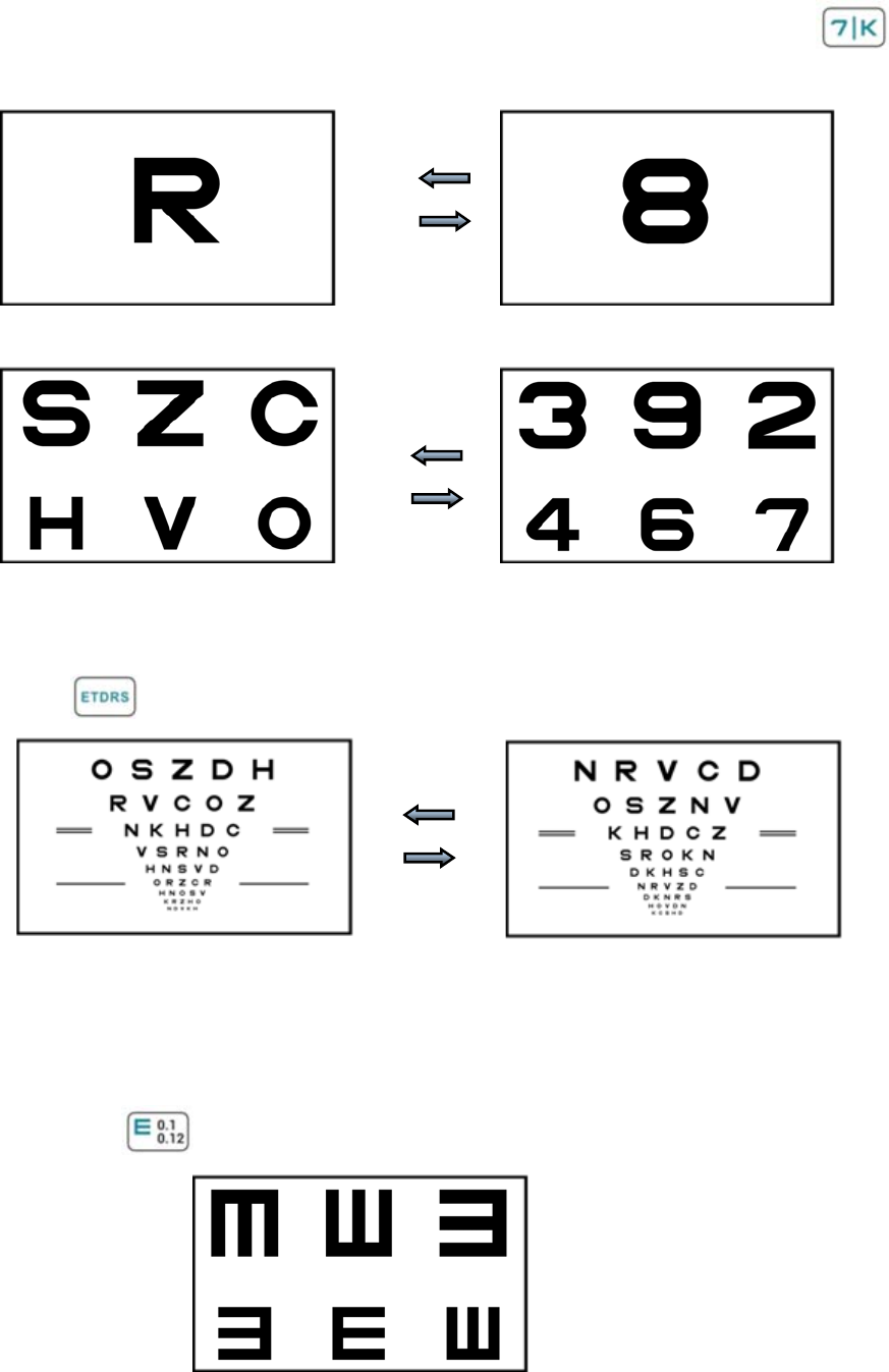
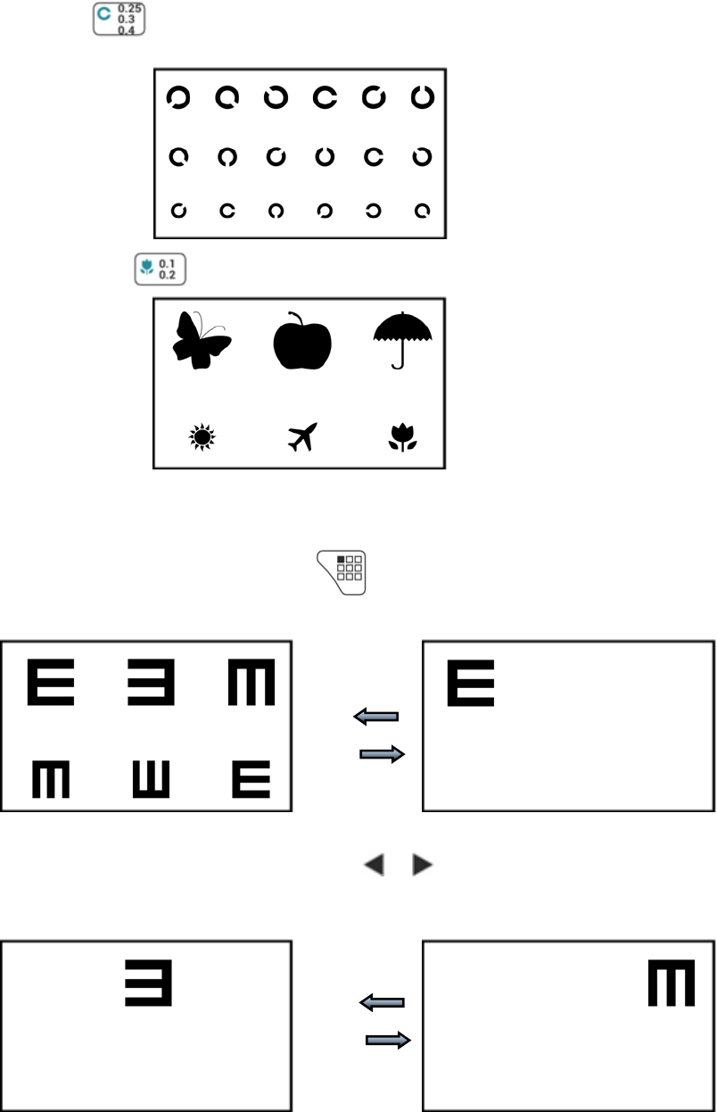
1)Visual Chart
Used for vision test, including 6 types Charts such as “E”, “C”, Letter, Number, Kids and ETDR.
2)Functional Chart (applies to YPB-2100)
Used for visual function test, including 14 functional Charts.
1.1.4 Testing range of vision
The testing ranges of all types of visual Charts are (in decimal): 0.05~2.0 for “E”, “C”, Letter and
Number, 0.05~1.0 for Kids and 0.3~2.0 for ETDRS.
The testing ranges of all types of visual Charts are (in Metric/6m): 150~3 for “E”, “C”, Letter and
Number, 150~7.5 for Kids and 20~3 for ETDRS.
The testing ranges of all types of visual Charts are (in Imperial/20ft): 500~10 for “E”, “C”, Letter and
Number, 500~25 for Kids and 63~10 for ETDRS.
Remarks: When the optometry distance is less than 2 meters, Visual Chart 2.0(unit:decimal),
3(Metric/6cm) and 10 (Imperial/20ft) are only for evaluation reference.

- 2 -
1.1.5 Visual Charts display modes: all, single, row and column.
1.1.6 Automatic screensaver: 3 mins, 5 mins and 10 mins are optional.
1.2 Power Supply Parameters
1) Input voltage AC 100V~240V(±10%)
2) Input frequency 50/60 Hz
3) Input power 70 VA
1.3 Weight and Size
1) Wall-mounted
Weight Host: about 4kg
Remote controller: about 80g
Size Host: 519mm (L) × 70mm (W) × 327.7mm (H)
Remote controller: 186mm (L) × 55mm (W) × 17.2mm (H)
2) Desktop
Weight Host: about 3.55kg
Remote controller: about 80g
Size Host: 519mm (L) × 167.5mm (W) × 391.7mm (H)
Remote controller: 186mm (L) × 55mm (W) × 17.2mm (H)
*Thedesignandspecificationsaresubjecttochangesduetotechnicalupdateswithoutadditionalnotice.
2.Safety Precautions
Please read the following precautions carefully to avoid personal injury, device damages or
other possible hazards:
●Use the device indoors and keep it clean and dry; do not use it under inflammable, explosive, high
temperature and dusty environment;
●Do not use the device near water; also be careful not to make any kinds of liquid drop onto the
device. Do not place the device in damp or dusty places, nor place it where humidity and temperature
change quickly;
●When mounting the device on the wall, make sure the wall is able to withstand the weight of 5 kg;
●When mounting the device on the wall, reserve a gap over 50mm all around the device;
●The device is hung on the rack. Be careful when touching the device on the wall: Upward

- 3 -
displacement may cause the device unhooked and fall, resulting in personal injury or device failure;
●Dedicated power adaptor configured for the device should be used:
model : UE36LCP1-140257SPA, Input 100-240V~0.9A 50-60Hz, Output14V 2.57A;
● Make sure the input voltage is consistent with rated input voltage and the electric wire is correctly
connected and well grounded;
●Do not use multiperture socket or extend the power cord to insert the plug of the device into power
socket;
●Unplug power cord and cut off power supply line especially under emergency circumstances; hold
the power plug to pull out it from the socket rather than pulling the power cord;
●Do not touch the power cord with wet hands. Check the power cord and do not allow the power cord
to be stamped, pressed by heavy objects or knotted;
●Power cord damage may cause fire or electric shock. Please check it regularly;
●Cut off power before cleaning or disinfecting the device;
●Do not dismantle or touch the interior parts of the device, otherwise it may cause electric shock or
device failure;
●The device has passed electromagnetic compatibility test. Follow below instructions related to EMC
(electromagnetic compatibility) when mounting and using the device:
- Do not use the device with other electric devices to avoid electromagnetic disturbance to
the device;
- Do not use the device nearby other electric devices to avoid electromagnetic disturbance
to the device;
- Do not use a power adaptor that is not configured with the device, otherwise it may
increase the electromagnetic emission amount, which may reduce the capacity of resisting
disturbance.
Caution: The user is cautioned that changes or modifications not expressly approved by the
party responsible for compliance could void the user's authority to operate the equipment.
This device complies with Part 15 of the FCC Rules. Operation is subject to the following two
conditions: (1) this device may not cause harmful interference, and (2) this device must accept any
interference received, including interference that may cause undesired operation.
- 4 -
NOTE: This equipment has been tested and found to comply with the limits for a Class B
digital device, pursuant to Part 15 of the FCC Rules. These limits are designed to provide reasonable
protection against harmful interference in a residential installation. This equipment generates, uses
and can radiate radio frequency energy and, if not installed and used in accordance with the
instructions, may cause harmful interference to radio communications. However, there is no
guarantee that interference will not occur in a particular installation.
If this equipment does cause harmful interference to radio or television reception, which can be
determined by turning the equipment off and on, the user is encouraged to try to correct the
interference by one or more of the following measures:
-- Reorient or relocate the receiving antenna.
-- Increase the separation between the equipment and receiver.
-- Connect the equipment into an outlet on a circuit different from that to which the receiver is
connected.
-- Consult the dealer or an experienced radio/TV technician for help.
FCC Radiation Exposure Statement:
This equipment complies with FCC radiation exposure limits set forth for an uncontrolled
environment. This equipment should be installed and operated with a minimum distance of 20cm
between the radiator and your body.
This transmitter must not be co-located or operating in conjunction with any other antenna or
transmitter.
- 5 -
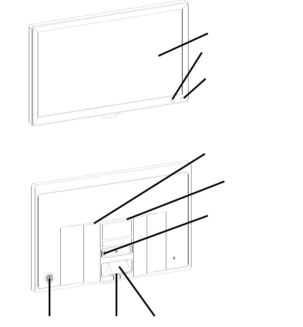
3.Main Structure
3.1 Host
3.1.1 Wall-mounted device (Hung on the wall)
Front diagram of the displayer (host)
Back diagram of the displayer (host)
1. LCD dis
p
la
y
e
r
6. Mountin
g
interface
4. DC-DC socket
5. Label
2. Si
g
nal receive
p
ort
3. Power indicato
r
7.Power switc
h
9. Audio Out
p
ut Jac
k
Are
a
8. 2 x USB 2.0 Ports Area
- 6 -
1. LCD displayer
Displays Charts and vision record.
2. Signal receive port
Receives signals from the remote controller.
3. Power indicator
Power indicator is lit on when the device is connected to power and enters standby mode.
4. DC-DC socket
Power adaptor socket.
5. Label
Product label.
6. Mounting interface
Mounting interface of the device.
7. Power switch
Power switch of the LCDLCD visual chart.
8. 2 x USB 2.0 Ports
Can carry out program upgrading, video and image play through USB flash disk.
9. Audio Output Jack
Connect to speaker.
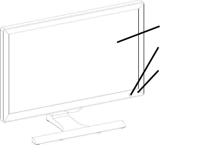
3.1.2 Desktop Device (Used on the worktable)
Front diagram of the displayer (host)
1. LCD dis
p
la
y
e
r
2. LCD dis
p
la
y
e
r
3. Power indicato
r
- 7 -
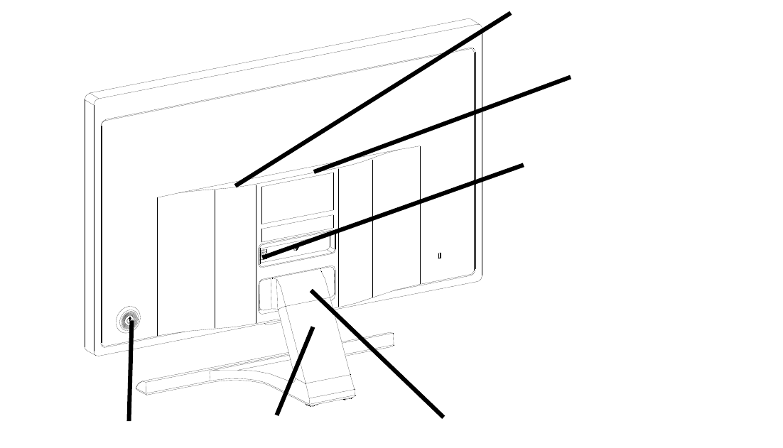
Back diagram of the displayer (host)
1. LCD displayer
Displays Charts and vision record.
2. Signal receive port
Receives signals from the remote controller.
3. Power indicator
Power indicator is lit on when the device is connected to power and enters standby mode.
4. DC-DC socket
Power adaptor socket.
5. Label
6. Pedestal
Pedestal of the device.
7. Power switch
Power switch of the LCD visual chart.
8. 2 x USB 2.0 Ports
Can carry out program upgrading, video and image play through USB flash disk.
9. Audio Output Jack
Connect to speaker.
6. Pedestal 5. Label
4. DC-DC socket
7. Power switch
9. Audio Out
p
ut Jac
k
Are
a
8. 2 x USB 2.0 Ports Area
- 8 -
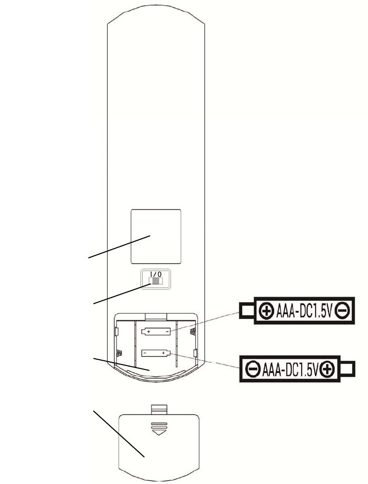
3.2 Remote Controller
Back diagram of the remote controller
1. Label
Remote controller label.
2. Switch
Remote controller switch.
3. Battery case
Install two AAA grade alkaline batteries
4. Battery cover
1. Label
3.Battery case
4. Battery cover
2. Switch
- 9 -
4 Installation
4.1 Part List
1) Displayer (host) 1 Set
2) Hex screw with round head 1 Pc
3) Rack 1 Pc
4) Cross-recessed wood screw with countersunk head 4 Pc
5) Wall bearing 1 Pc
6) Plastic expansion pipe 4 Pc
7) Remote controller 1Pc
8) Red-and-green glasses 1 Pair
9) Hex wrench (2.5mm) 1Pc
10) Power adaptor 1Pc
11) Pedestal 1Pc
12) Connecting screw 1Pc
13) Supporting base 1Pc
- 10 -
4.2 Installation Instructions
4.2.1 Installation Instructions for Wall-mounted Device
When installing the device on the rack, make sure to hang the device on the wall that is
able to withstand a weight of 5kg. Reinforce the wall if necessary.
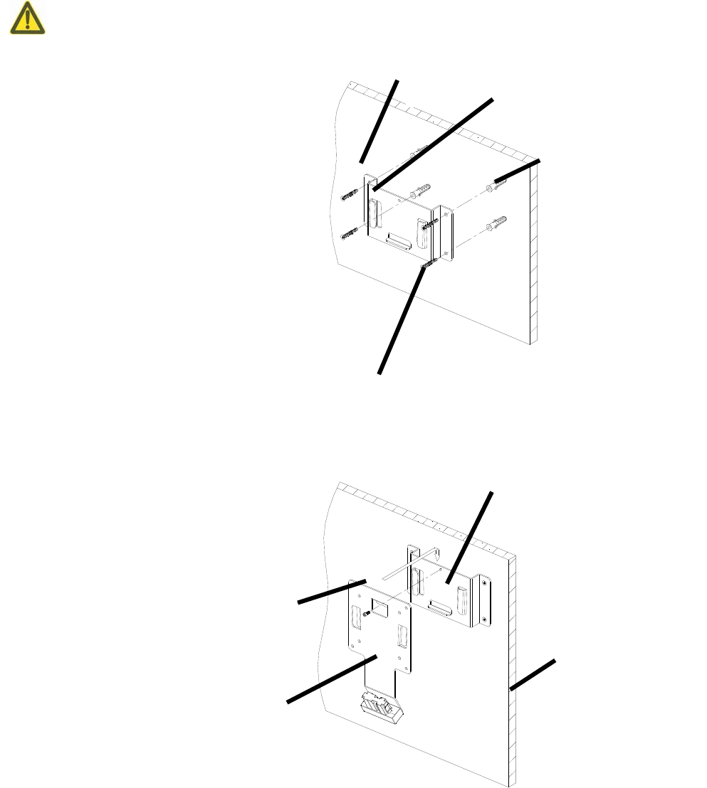
4.2.1.1 Installation of wall bearing
Drill appropriate installation holes in
the wall body and insert the plastic expansion pipe.
hen, penetrate 4 cross-recessedwood screws with
countersunk head through the installation holes,
screw into the plastic expansion pipes and install
the bearing onto the wall.
Keep the rack level during installation.
4.2.1.2 Installation of rack
Mount the rack into the wall bearing and tighten
the hex screw with round head the hex wrench.
Wall bearin
g
Hex screw with round hea
d
Rac
k
Wall
Wall bearin
g
Wall bod
y
p
lastic ex
p
ansion
p
i
p
e
Cross-recessed wood screws with countersunk hea
d
- 11 -
4.2.1.3 Installation of the device
Hang the device on the hook of the rack as showed in the figure.
On the hearing of buckle clatter, it indicates that the installation
is finished.
Reserve at least 50mm gap all around the device to ventilate
the device.
4.2.2 Installation Instructions for Desktop Device
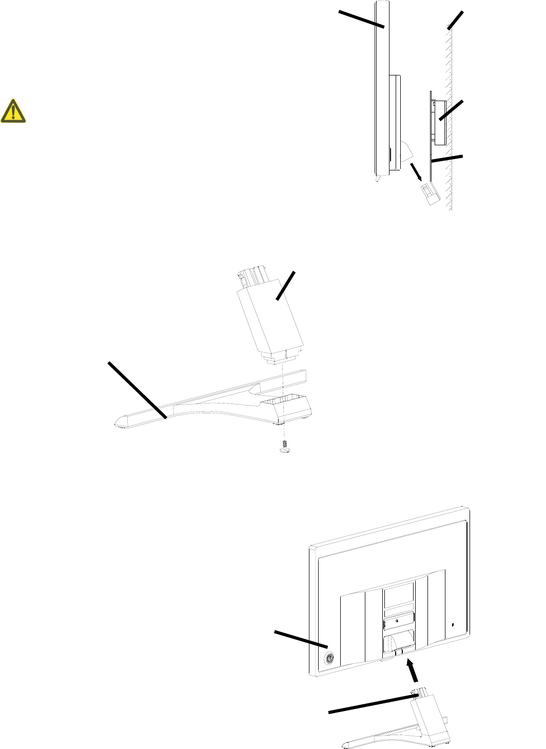
4.2.2.1 Installation of Pedestal
Install the supporting base into the Pedestal, and then penetrate theconnecting screws into the
Pedestal and screw into the supporting base and tighten it.
4.2.2.2 Installation of displayer
Place a cushion or a soft cloth on a tidy desk and then put the displayer on the cushion or cloth
facing down.
Insert the Pedestal into the installation port as shown in
the figure.
On the hearing of buckle clatter, it indicates that the
installation is finished.
Wall bod
y
Dis
p
la
y
e
r
Rac
k
Wall bearin
g
Su
pp
ortin
g
base
Pedestal
Installation
p
ort
Dis
p
la
y
e
r
- 12 -
4.2.3 LCD Dip Angle Adjustment
After Installation, hold the top edge of the LCD screen, Turn forward or back to adjust the dip
angle of LCD screen.
5. Directions for Use
5.1 Device Startup and Shutdown
5.1.1 Device startup
5.1.1.1 Turn on the displayer.
Press the power switch to turn on the displayer.
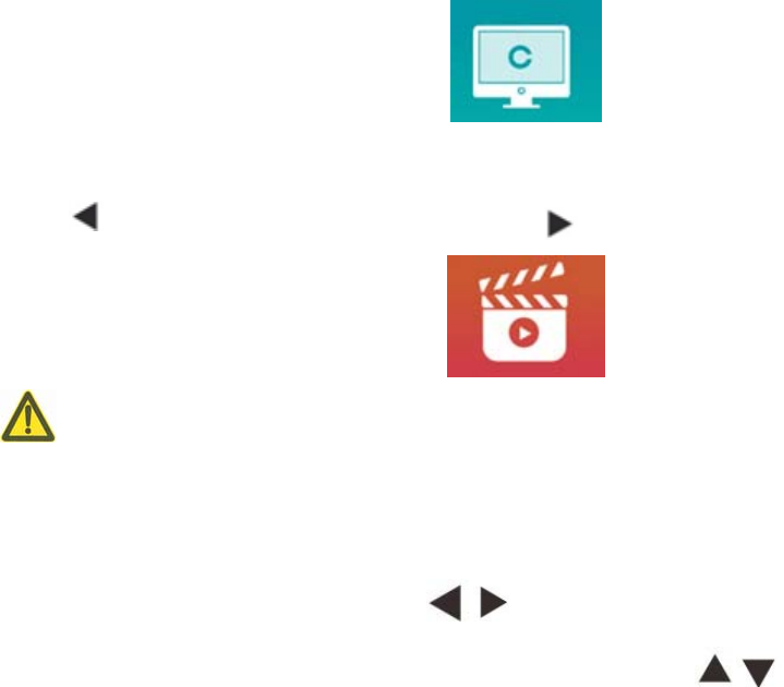
5.1.1.2 Main module: When choosing module,press OK key to enter。
VISION TEST: Visual Test。
VIDEO PLAYER: Can carry out program upgrading, video and image play through USB flash disk.
Press key to fold USB flash disk folders, press key to unfold, press OK key to play.
It is recommended to unplug the adapter firstly, then plug the USB flash disk, otherwise
there is the risk of file damage.
After selecting the video file, press the OK button to start playing. Fast forward and backward
through the left and right selection keys (each change time is 30 seconds);
Adjust the volume through the up and down selection keys ; press the OK button to
pause during the video playing process. Press other keys to exit video playing.
EYES $ VISON:Functional Test, including Contrast sensitivity Function, Structure of Eye and
Vision
- 13 -
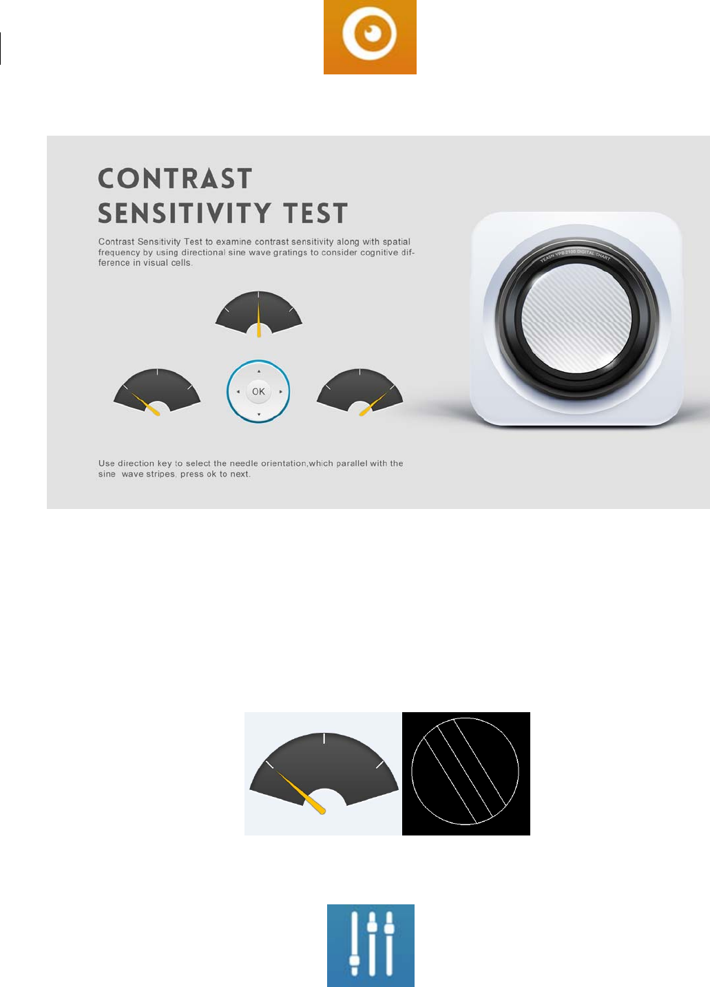
CSF Test:
①Select the contrast sensitivity functional (CSF) and press the OK button to enter the test interface.
②Start the measurement by pressing the OK button.
③The direction of the measured image can be controlled by the direction key of the remote
controller. The picture pointer will follow the change. If you can confirm the direction of the picture,
press the OK button to select, and if you can't, press the OK button to skip the determination of the
picture directly.
④The test results will be displayed after all the pictures have been determined.
SETTINGS:Setting Parameters.
- 14 -
5.1.1.3 Chart display
Aim the signal emitter of the remote controller at the signal receive port of the displayer and then
press the chart key on the controller to select the chart you need.
5.1.2 Recover from screensaver status
The displayer is automatically turned off and enters screensaver status when the device stops working
for 3 minutes (you can also set it to 5 minutes, 10 minutes). Press any key on the controller to light up
the displayer and enter working state.
5.1.3 Device shutdown
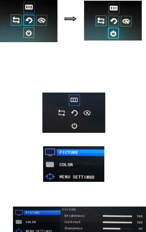
Press the power switch, select Shutdown icon and then press again to turn off the displayer.
5.1.4 Brightness Adjustment
(~ )
The brightness of the test zone of this equipment is 80 320 cd/m2.
The way to adjust brightness is as follows: Press the Power button and move the Power button up
to choose Menu icon and then press the power button again to enter Menu interface.
Choose “Image”by press Up and Down button.
Press Right button to choose Brightness option and press Power button and enter Brightness
Adjustment interface.

- 15 -
Press Right button to increase brightness and press Left button to decrease brightness.
Except brightness, all other parameters have been well set up, please do not make any change.
Otherwise, it may have an impact on the normal use of the LCD visual chart.
- 16 -
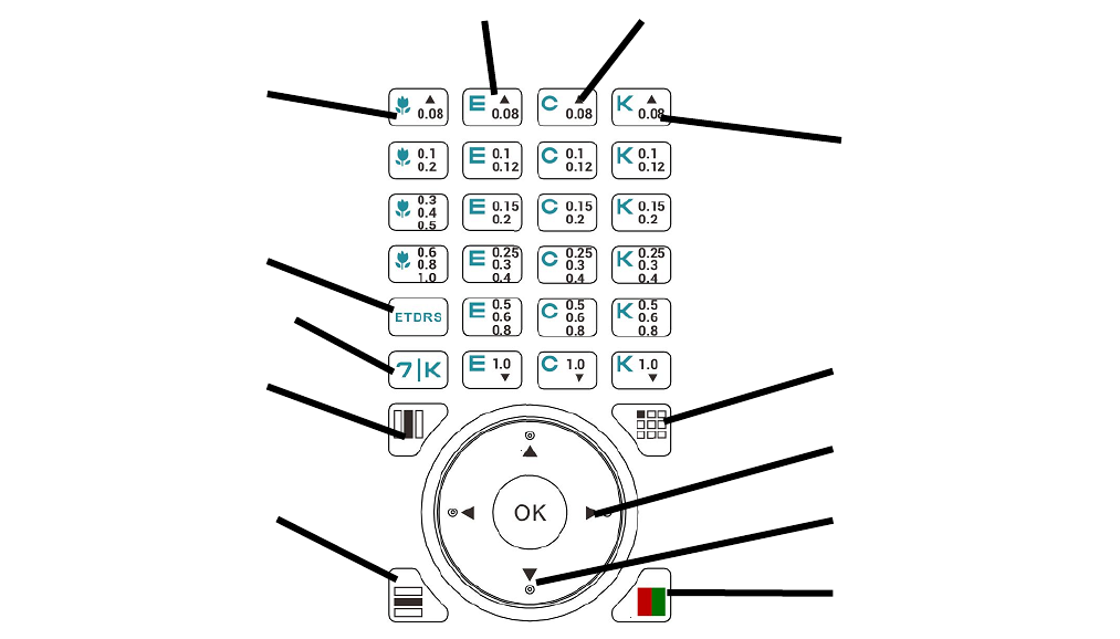
5.2 How to use the Remote Controller
5.2.1 Remote controller
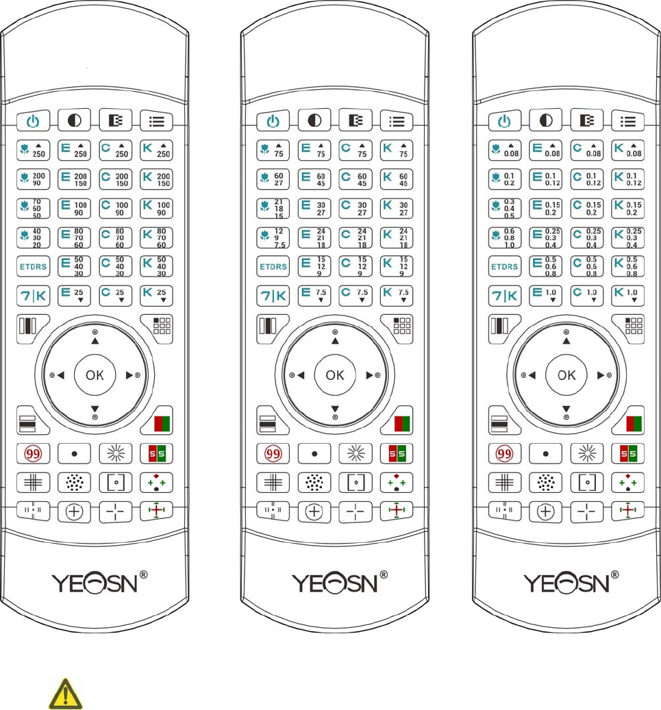
There are three remotes available for option: Decimal standard, Inch standard and Metric Standard
Below examples are based on Decimal standard remote
- 17 -
Setup Methods of Multi-Channel for Remote Controller
Before entering multi-channel setup, to make sure only one LCD visual chart within
operation region and be in working. Otherwise, will possibly cause operation mistake to other LCD
visual chart
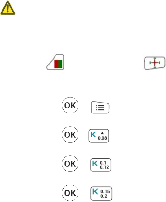
First, to press one time, and then press one time. Repeat 3 times and then
automatically enter the setup mode of channel
Continuously press + 3 seconds and visual chart will be set as channel 1
Continuously press + 3 seconds and visual chart will be set as channel 2
Continuously press + 3 seconds and visual chart will be set as channel 3
Continuously press + 3 seconds and visual chart will be set as channel 4
- 18 -
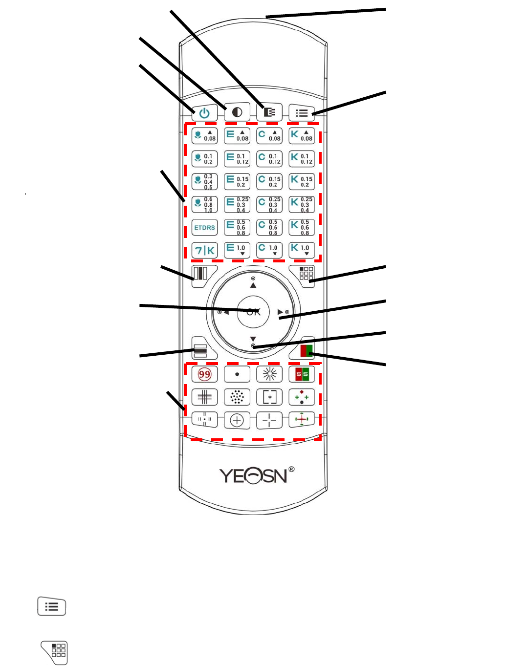
Front diagram of the remote controller
1. Signal emitter
Emit signals to the displayer.
2. Parameter setup key
Set up device parameters.
3. Single display key
1.Si
g
nal emitte
r
2. Parameter setu
p
ke
y
3. Sin
g
le dis
p
la
y
ke
y
4.Left-ri
g
ht selection ke
y
5. U
p
-down selection ke
y
6. Re
d
-Green Mas
k
ke
y
14. Black and white shift ke
y
13. Contrast ke
y
12. Switch ke
y
11. Visual chart selection are
a
10. Column dis
p
la
y
ke
y
9. Rando
m
and O
K
ke
y
8. Row dis
p
la
y
ke
y
7. Functional chart selection are
a

- 19 -
Press this key to shift between single chart and all charts: press once to display single chart, press
again to display all charts.
4. , Left-right selection key
When single chart displays or charts display in column, press this key to shift the chart left or right on
the same visual chart.
5. , Up-down selection key
When visual charts display, press this key to display last or next screen of visual charts.
When single chart displays or charts display in column, press this key to shift the chart up or down on
the same visual chart.
6. Red-Green Mask key
Press this key the Red-Green background will be loaded.
7. Functional chart selection area
Select charts with functions to be tested.
8. Row display key
Press this key to shift between row charts and all charts: press once to display row chart, press again
to display all charts.
9. Random and OK key
Press this key,the slection of visual chart can be randomized.
10. Column display key
Press this key to shift between column charts and all charts: press once to display column chart, press
again to display all charts.
11. Visual chart selection area
Select charts to test vision.
12. Switch key
Turn on or off the LCD displayer. The host can’t be started up or shut down by pressing this key.
13. Contrast key
Select Chart contrast. Press this key to shift among 100% → 25% → 12% → 6% → 100% in loop.
14. Black and white shift key
Press this key to shift the Charts between black mark on white background and white mark on black
background.

- 20 -
5.2.2 About the battery in the remote controller
Two AA before use.
Take out these batteries if the device will not be used for a period of time.
Attention:
●
Donotuseordinaryacidbaery,onlyalkalinebaeriescanbeusedtoavoiddevicedamageduetobattery
leakage.
●
Payaenontothepolarityofthebaerywhenreplacingit.
●
Disposeofusedbaeryproperlytoavoidenvironmentpolluon.
●
Operatorisnotallowedtotouchthebaerandthepaentatthesameme.
- 21 -
5.3 Visual chart Display
5.3.1 Visual chart display
Press the chart key on the controller as needed to display corresponding chart.
There are six types of charts in visual chart selection area: “E” chart, “C” chart, Letter chart, Number
chart, Kids chart and ETDRS chart.
Letter Chart
Kids Char
t
“E” Chart
Letter-Number shift key
“C” Chart
ETDRS Chart
Single Chart key
Left-right selection key
U
p
-down selection ke
y
Red and Green Mas
k
Column Chart ke
y
Row Chart key
- 22 -
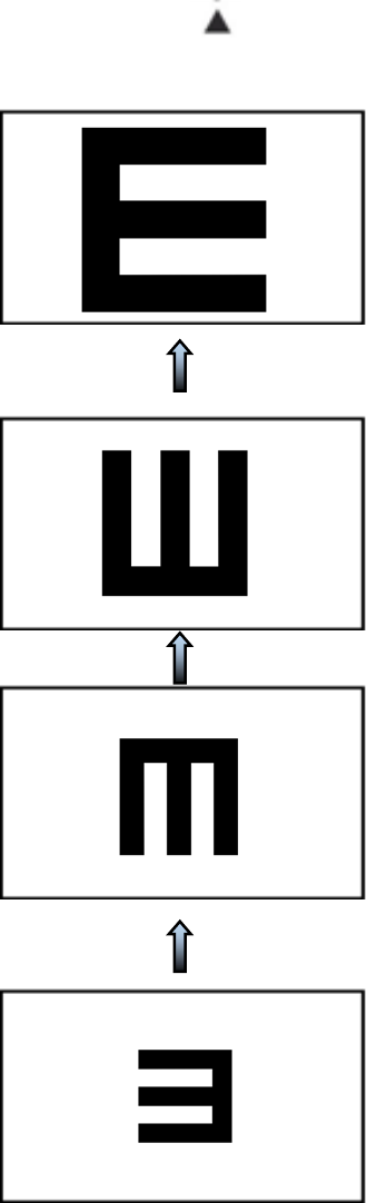
5.3.1.1 0.04, 0.05 and 0.06 charts display
When 0.08 chart displays, press to display 0.04, 0.05 and 0.06 charts.
E.g.: 0.04, 0.05 and 0.06 “E” charts display
0.04
0.05
0.06
0.08
- 23 -
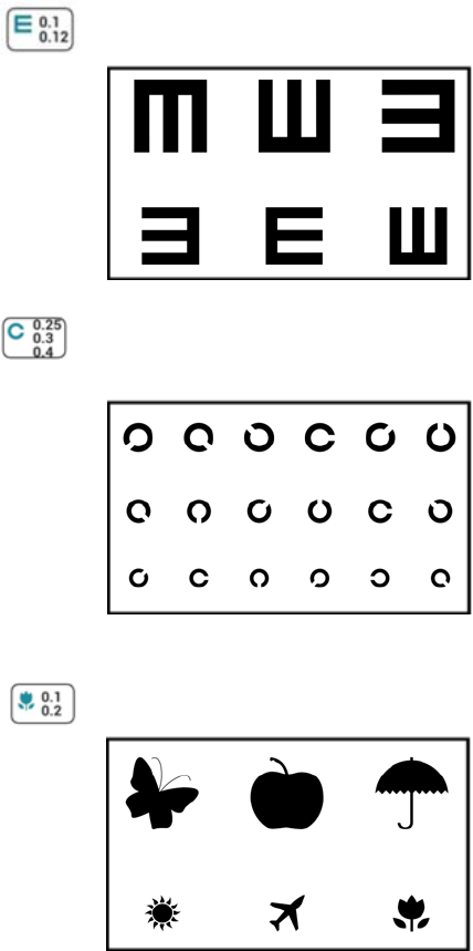
5.3.1.2 “E”, “C” and Kids charts display
1)Press chart keys to display
Press the chart key on the controller as needed to display corresponding chart.
E.g.: Press to display 0.1 and 0.12 “E” charts.
0.1
0.12
E.g.:Press to display 0.25, 0.3 and 0.4 “C” charts.
0.25
0.3
0.4
E.g.: Press to display 0.1 and 0.2 Kids charts.
0.1
0.2
- 24 -
2)Press Up-down selection key to display
When a screen of charts displays, press Up-down selection key to display last or next
screen of charts. For example:
0.06
0.08
0.1
0.12
0.15
0.2
0.25
0.3
0.4
- 25 -
5.3.1.3 Number and Letter charts display
When a screen of Number (Letter) charts display, press Letter-Number shift key to shift to
Letter (Number) charts with the same vision.
0.08 0.08
0.15 0.15
0.2 0.2
5.2.1.4 ETDRS charts display
Press once to display one screen of ETDRS charts, press again to display the other.
5.3.2 Visual charts display modes
5.3.2.1 Full word charts display
Press the chart key on the controller as needed to display corresponding full word charts (default).
E.g.: Press to display all 0.1 and 0.12 full “E” charts.
0.1
0.12
- 26 -
E.g.: Press to display all 0.25, 0.3 and 0.4 full “C” charts.
0.25
0.3
0.4
E.g.: Press to display all 0.1 and 0.2 Kids charts.
0.1
0.2
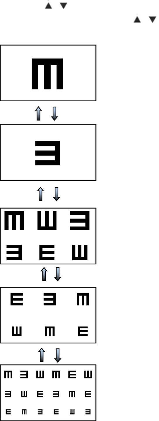
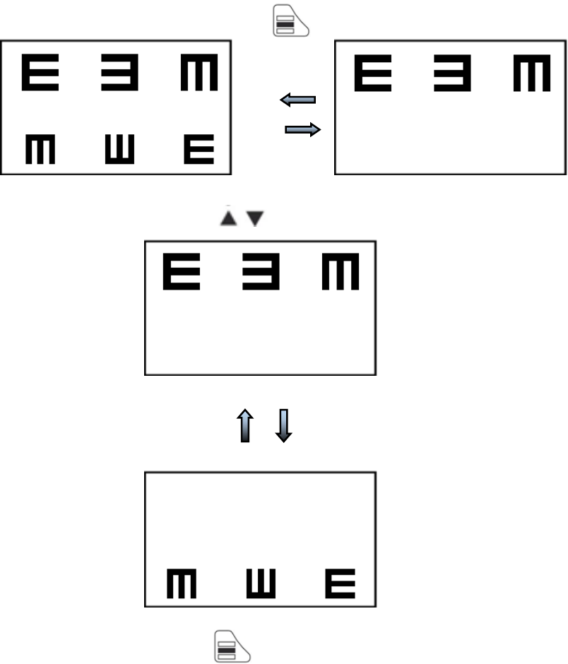
5.3.2.2 Single word chart display.
When full word charts display, press to display single word chart.
0.1 0.1
0.12 0.12
When one single word charts display, press to display another single word chart in one row.
For example:
0.1 0.1
0.12 0.12

- 27 -
When one single Charts displays, press to display another single Chart in last or next row.
For example:
0.1
0.12
0.1
0.12
When single word chart displays, press to recover full word charts.
- 28 -
5.3.2.3 Row charts display
When full word charts display, press to display row charts. For example:
0.1 0.1
0.12 0.12
When row charts display, press to display last or next row of charts. For example:
0.1
0.12
0.1
0.12
When row charts display, press to recover full wordcharts.
- 29 -
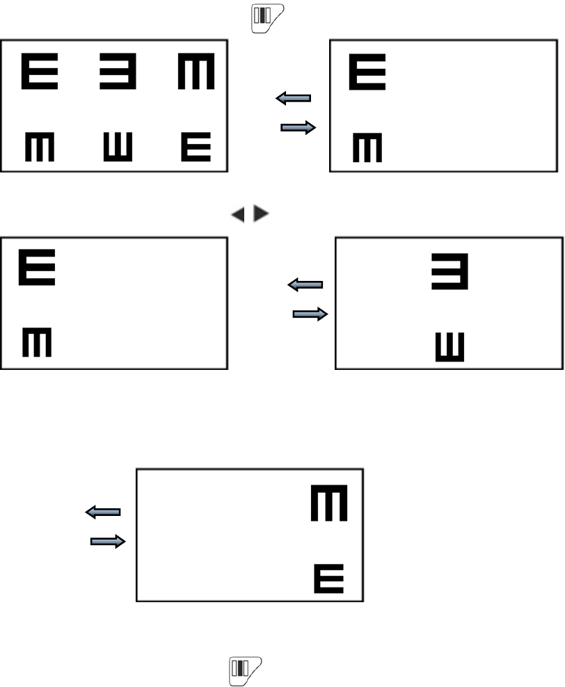
5.3.2.4 Column charts display
When full word Charts display, press to display column charts. For example:
0.1 0.1
0.12 0.12
When column charts display, press to display left or right column of charts. For example:
0.1 0.1
0.12 0.12
0.1
0.12
When column charts display, press to recover all charts.
- 30 -
5.3.3 Visual chart change
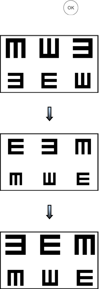
When a screen of charts display, press key to display the randomly rearranged charts.
0.1
0.12
0.1
0.12
0.1
0.12
- 31 -
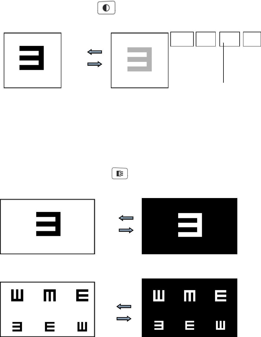
5.3.4 Chart contrast
Chart contrast function is used to evaluate the contrast sensitivity and observe the changes of visual
acuity under low contrast conditions.
This device provide four options of contrast which are 100%、25%、12%、6%.
When a chart displays, press key, the contrast of chart can be shifted following
100%→25%→12%→6%→Exit
0.08 0.08
5.3.5 Black and white shift
The black and white shift of the charts are used for amblyopia test, and the vision value is just for
reference.
The black charts are on white background during normal use and white charts are on black
background when reversing it.
When a screen of chart displays, press the charts can shift between black characters on white
background and white characters on black background. For example:
0.08 0.08
0.15 0.15
0.2 0.2
100% 25% 12% 6%
Contrast Sigm

- 32 -
5.4 Functional chart Display
Press the functional chart key on the remote controller to display corresponding icons.
5.4.1 Functional chart display
There are 14 types of functional charts in the functional chart selection area of the device used to test
the binocular vision balance, binocular simultaneous perception, fusion, binocular image inequality,
heterophoria, binocular stereopsis and other visual functions.
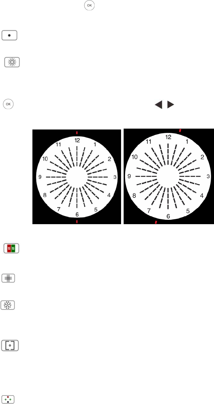
5.4.1.1 The types of functional charts are shown below:
1 2 3 4
5 6 7 8
9 10 11 12
1. Ishihara 2.Maddox rod 3.Astigmatic disc 4.Red and green 5.Cross grid 6.Speckle
7.Vertical alignment and Horizontal alignment 8.Worth 4 points 9.Stereo
10.Cross ring 11.Cross and Cross and dot 12.Clock disc
TheYPB‐2100Charthasnopolarizationfunction.
5.4.1.2 Functional chart display
1.Ishihara Chart
Press key, the color blindness will pop-up. Press key to shift among different
- 33 -
color blindness visual charts. Press key, shows the test result.
2. Maddox rod chart
Press to display Maddox rod chart, used to test heterophoria.
3. Astigmatic disc chart (two options)
Press there are two chart options, solid line and dotted line astigmatic discs, Each pressis to
shift between these two charts. They have the same function, both used to test astigmatic axial and
degree.
Press key, display red indicating visual chart. Press to adjust the location of red
indicating visual chart.
4. Red and green Chart
Press to display red and green chart, used to test spherical vision.
5. Cross grid chart
Press to display cross grid Chart, used to test spherical vision.
6.Speckle Chart
Press to display speckle chart, used in crisscross cylinder to test astigmatic axial and degree and
binocular vision balance.
7. Vertical alignment and Horizontal alignment chart
Press to display red and green vertical alignment chart, used to test vertical heterophoria and
binocular image inequality. Press again, to display red and green horizontal alignment chart, used to
test horizontal heterophoria and binocular image inequality.
8. Worth 4 Dots chart
Press to display Worth 4 Dots chart, used to test binocular simultaneous perception, fusion and
- 34 -
euphoropsia.
9. Stereo chart
Press to display red and green stereo chart, used to test stereopsis.
10. Cross ring chart
Press to display red and green cross ring chart, used to test heterophoria.
11. Cross chart and cross fixation chart (two options)
Press there are two chart options, red and green cross chart and red and green cross and dot
chart; Each press can shift between these two Charts. They have the same function, both used to test
heterophoria.
12. Clock disc Chart
Press to display clock disc chart, used to test rotatory heterophoria.
5.5 Parameter Setup
1.Press to enter parameter setup interface.
2.Press to select needed parameters to change parameter setup. When the item
to be set up is selected, the item is highlighted.
3. When the setup is finished, press to return to test interface.
The detailed parameters are set up as follows:
1) Language: Chinese, English
Factory default: Chinese
2)Distance (meter): 1.5m- 7.3m, step:0.1m.
Factory default: 5m
Distance (feet): 5ft- 24ft, step:0.5ft.
Factory default: 20ft.
Optometry distance can be set based on the situation of the optometry room.
3)Balance: 155, 160, 165, 170, 175, 180, 185, 190 and 195.
Factory default: 175
Take 5 as step to set up green to make red and green equilibrated.
4)Mirror: normal and mirror
Factory default: normal
Set normal chart display and mirror chart display.
- 35 -
5)Unit : decimal, 5-Grade, Metric, Imperial, LogMAR
Factory default: decimal
Set vision value display method.
)
6System
Screensaver : off, Blank Screen, play video (product promotion material)
Factory default: close screensaver
Stand-by time: 3 min, 5 min and 10 min
Factory default: 3 min
Buzzer:Off,On
Vision: After being selected, display different pictures to judge the far and near visual ability.
Initial Chart: Default Chart,Current Chart
Default Chart:Turn on the Chart, “E”chart will be displayed。
Current Chart: Turn on the Chart,selected chart will be displayed。

- 36 -
6. Troubleshooting
In the event of device trouble, please check the device as per below chart to obtain guidance. If the
trouble is not shot, please contact with Chongqing Yeasn Science & Technology Co., Ltd.
Maintenance Department or the authorized dealer.
Trouble Reasons Solutions
Displayer is not bright The power cord is not
correctly connected to the
socket
Connect the power cord
correctly
Visual chart is not clear The displayer is not clean Clear up the displayer
Visual chart disappears
suddenly
The device enters standby
mode
Press any key on the
controller
Remote controller keys don’t
work
There is an obstacle between
the controller and the
displayer
Move away the obstacle
Wrong installation of battery Install the battery correctly
Insufficient battery capacity Replace the battery

- 37 -
7. Cleaning and Protection
Attention: Do not use any corrosive detergent to clean the device, so as not to damage the
device surface.
7.1 Clean LCD displayer
You need to clean the LCD screen if it’s too dirty to see the visual chart clearly.
1)Cut off power.
2)Unplug the power cord from the socket.
3)Wipe the LCD screen with soft and clean cotton cloth or absorbent wool gently.
Attention: Cut off power and unplug the power cord from the socket before cleaning.
Otherwise, it may cause electric shock.
Attention: Do not wipe the LCD screen with stiff cloth or paper; otherwise it may scratch the
screen.
Attention: Make sure not to leave water drop on the LCD screen; if there is a water drop, please
wipe it away with soft and clean cotton cloth or absorbent wool.
Otherwise, it may leave a stain on the LCD screen,
Attention: Wipe the LCD screen gently when cleaning it. Otherwise, it may cause device failure.
7.2 Clean external parts
When the external parts, such as the enclosure or panel, get dirty, please wipe them gently with clean
and soft cloth.
For intractable stains, please dip the clean soft cloth in mild detergent to scrub the stains away and
then wipe it with dry soft cloth.

- 38 -
8. Maintenance
To guarantee the normal and safe operation of the equipment, a preventive check and maintenance
should be conducted for the ME equipment and its parts every 6-12 months (including performance
check and safety check)
8.1 Replace battery
Follow below steps to change the battery
1)Remove battery cover.
2)Take out old batteries.
3)Put in new batteries.
4)Install battery cover.
Attention: Do not use ordinary acid batteries, only alkaline batteries can be used.
Otherwise, it may cause device damage due to battery leakage.
Attention: Pay attention to the polarity of the battery during installation, making sure the
polarity of the battery is consistent with the polarity mark ○
+ and ○
- in the battery case.
Otherwise, the remote controller will not work; moreover, the controller may not work due to battery
leakage.
Attention: Please dispose of the used battery properly to avoid environmental pollution.
8.2 Repairable and replaceable parts, such as remote controller and power adapter, etc., provided by
the company can only be used; other unauthorized parts may reduce the minimum safety of the
device.
8.3 The fuse of the device is included in the power adapter; if damaged, please replace it with the
power adapter provided by the company with fuse type of T3.15A/250V.
8.4 Do not disassemble or repair the device arbitrarily when a failure occurs, please contact with local
dealer or manufacturer.
8.5 The company is committed to providing users with necessary circuit diagrams, part list and other
relevant materials as needed.
- 39 -
9.Environmental Conditions and Service Life
9.1 Environmental conditions for normal operation
Environment temperature: 10℃~35℃
Relative humidity: 30%~80% (no condensation)
Atmospheric pressure: 800hPa~1060hPa
Indoor conditions: clean and without direct high light.
9.2 Environmental conditions for transportation and storage
Environment temperature: -10℃~+45℃
Relative humidity: 10%~90% (no condensation)
Atmospheric pressure: 700hPa~1060hPa
Indoor conditions: good ventilation and without corrosive gas.
9.3 Service life
The service life of the device is 8 years from first-time use with proper maintenance and care.

- 40 -
10. Environmental Protection
Please recycle or properly dispose of the used batteries and other wastes to protect the environment;
please package the device at the end of life to the company, or handle it in accordance with local
provisions related to environmental protection.
11. Manufacturer’s Responsibility
The company is responsible for the safety, reliability and performance impact under below
circumstances:
- Assembly, addition, modifications, alterations and repairs are carried out by authorized
personnel by the company;
- Electrical facilities in the room are in conformity with relevant requirements, and
- The device is used according to the User Manual.
12. Symbol Description
The applied part of the device is Type BF
Class II device
Attention! Please refer to accompanying documents.
Refer to instruction manual/ booklet
Manufacture date
MFG. DATE Manufacture date
Manufacturer
European certificate of conformity
Correct Disposal of This Product (Waste Electrical & Electronic Equipment) Statement:
Contact the local authorities to determine the proper method of disposal of potentially
bio-hazardous parts and Accessories.
Product serial number
- 41 -
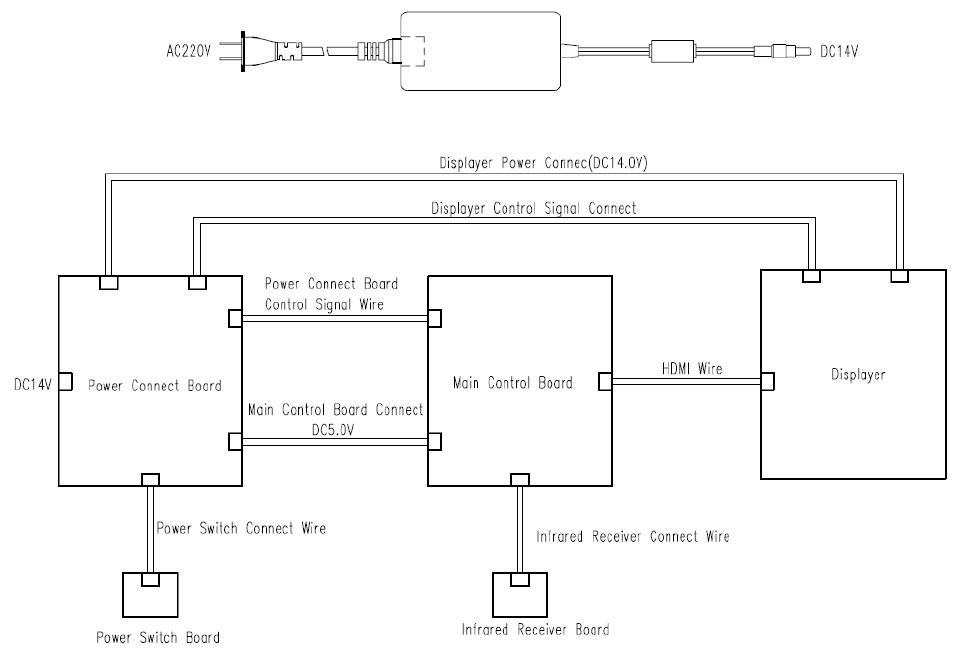
13. Electrical Schematic Diagram
For further information and services, or any questions, please contact with the authorized dealer or
manufacturer. We will be happy to help you.
- 42 -
14. Guidance of EMC and other interference
1)* This product needs special precautions regarding EMC and needs to be installed and put into
service according to the EMC information provided, and this unit can be affected by portable and
mobile RF communications equipment.
2)* Do not use a mobile phone or other devices that emit electromagnetic fields, near the unit. This
may result in incorrect operation of the unit.
3)* Caution: This unit has been thoroughly tested and inspected to assure proper performance and
operation!
4) * Caution: this machine should not be used adjacent to or stacked with other equipment and that if
adjacent or stacked use is necessary, this machine should be observed to verify normal operation in
the configuration in which it will be used.
Guidance and manufacture’s declaration – electromagnetic emission
The YPB-2100/YPB-2100P is intended for use in the electromagnetic environment specified
below. The customer of the user of the YPB-2100/YPB-2100P should assure that it is used in such
an environment.
Emission test Compliance Electromagnetic environment – guidance
RF emissions
CISPR 11
Group 1
The YPB-2100/YPB-2100P use RF energy only for its internal
function. Therefore, its RF emissions are very low and are not
likely to cause any interference in nearby electronic
equipment.
RF emission
CISPR 11
Class B
The YPB-2100/YPB-2100P is suitable for use in all
establishments, other than domestic and those directly
connected to the public low-voltage power supply network
that supplies buildings used for domestic purposes.
Harmonic
emissions
IEC 61000-3-2
Class A
Voltage
fluctuations/
flicker
emissions
IEC 61000-3-3
Complies
- 43 -
Guidance and manufacture’s declaration – electromagnetic immunity
The YPB-2100/YPB-2100P is intended for use in the electromagnetic environment specified below.
The customer or the user of YPB-2100/YPB-2100P should assure that it is used in such an
environment.
Immunity
test IEC 60601
test level Compliance
level Electromagnetic environment - guidance
Electrostatic
discharge
(ESD)
IEC
61000-4-2
±6 kV contact
±8 kV air
±6 kV
contact
±8 kV air
Floors should be wood, concrete or ceramic tile. If
floor are covered with synthetic material, the
relative humidity should be at least 30%.
Electrical
fast
transient/bur
st
IEC
61000-4-4
±2 kV for
power supply
lines
±1 kV for
input/output
lines
±2kV for
power
supply lines
Mains power quality should be that of a typical
commercial or hospital environment.
Surge
IEC
61000-4-5
± 1 kV line(s)
to line(s)
± 2 kV line(s)
to earth
±1 kV
differential
mode
Mains power quality should be that of a typical
commercial or hospital environment.
Voltage dips,
short
interruptions
and voltage
variations on
power
supply input
lines
IEC
61000-4-11
<5% UT
(>95% dip in
UT)
for 0.5 cycle
40% UT
(60% dip in
UT)
for 5 cycles
70% UT
(30% dip in
UT)
for 25 cycles
<5% UT
(>95% dip in
UT)
for 5 sec
<5% UT
(>95% dip in
UT)
for 0.5 cycle
40% UT
(60% dip in
UT)
for 5 cycles
70% UT
(30% dip in
UT)
for 25 cycles
<5% UT
(>95% dip in
UT)
for 5 sec
Mains power quality should be that of a typical
commercial or hospital environment. If the user of
the YPB-2100/YPB-2100P requires continued
operation during power mains interruptions, it is
recommended that the YPB-2100/YPB-2100P be
powered from an uninterruptible power supply or a
battery.
Power
frequency
(50Hz/60Hz
) magnetic
field IEC
61000-4-8
3 A/m 3 A/m Power frequency magnetic fields should be at
levels characteristic of a typical location in a typical
commercial or hospital environment.
NOTE UT is the a.c. mains voltage prior to application of the test level.
- 44 -
Guidance and manufacture’s declaration – electromagnetic immunity
The YPB-2100/YPB-2100P is intended for use in the electromagnetic environment specified below. The customer
or the user of the YPB-2100/YPB-2100P should assure that it is used in such an environment.
Immunity test IEC 60601 test level Compliance
level Electromagnetic environment - guidance
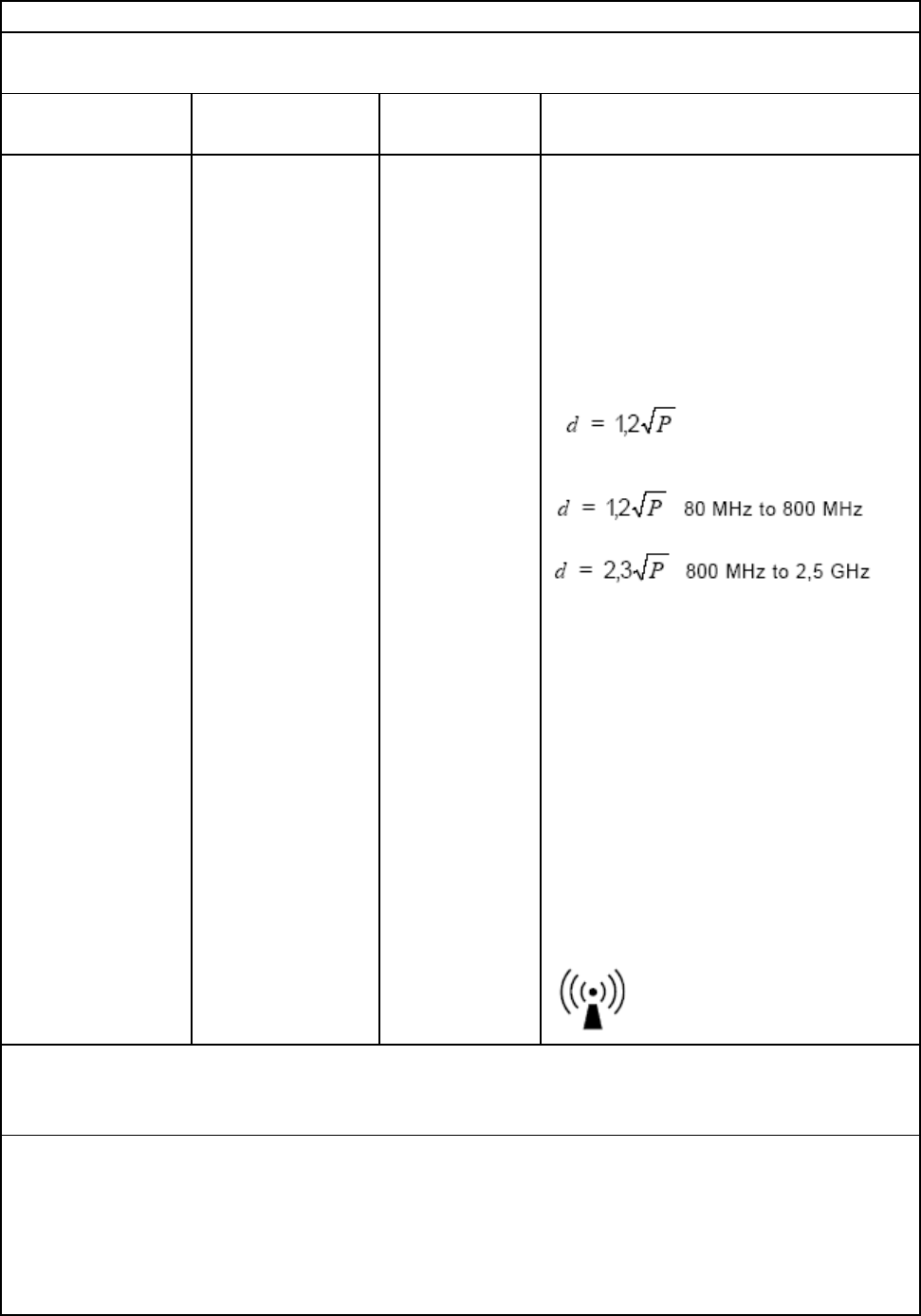
Conducted RF
IEC 61000-4-6
3 Vrms
150 kHz to 80 MHz
3 Vrms
Portable and mobile RF communications
equipment should be used no closer to any
part of the YPB-2100/YPB-2100P, including
cables, than the recommended separation
distance calculated from the equation
applicable to the frequency of the transmitter.
Recommended separation distance
Where P is the maximum output power rating
of the transmitter in watts (W) according to
the transmitter manufacturer and d is the
recommended separation distance in metres
(m).
Field strengths from fixed RF transmitters, as
determined by an electromagnetic site
survey,a should be less than the compliance
level in each frequency range.b
Interference may occur in the vicinity of
equipment marked with the following
symbol:
Radiated RF
IEC 61000-4-3
3 V/m
80 MHz to 2.5 GHz
3 V/m
NOTE 1 At 80 MHz and 800 MHz, the higher frequency range applies.
NOTE 2 These guidelines may not apply in all situations. Electromagnetic propagation is affected by
absorption and reflection from structures, objects and people.
a Field strengths from fixed transmitters, such as base stations for radio (cellular/cordless) telephones and
land
mobile radios, amateur radio, AM and FM radio broadcast and TV broadcast cannot be predicted theoretically
with accuracy. To assess the electromagnetic environment due to fixed RF transmitters, an electromagnetic site
survey should be considered. If the measured field strength in the location in which the YPB-2100/YPB-2100P is

- 45 -
used exceeds the applicable RF compliance level above, the YPB-2100/YPB-2100P should be observed to verify
normal operation. If abnormal performance is observed, additional measures may be necessary, such as
re-orienting or relocating the YPB-2100/YPB-2100P.
b Over the frequency range 150 kHz to 80 MHz, field strengths should be less than 3 V/m.
Recommended separation distances between
portable and mobile RF communications equipment and the YPB-2100/YPB-2100P .
The YPB-2100/YPB-2100P is intended for use in an electromagnetic environment in which radiated RF
disturbances are controlled. The customer or the user of the YPB-2100/YPB-2100P can help prevent
electromagnetic interference by maintaining a minimum distance between portable and mobile RF
communications equipment (transmitters) and the YPB-2100/YPB-2100P as recommended below, according to the
maximum output power of the communications equipment.
Rated maximum output power of
transmitter
(W)
Separation distance according to frequency of transmitter
(m)
150 KHz to 80
MHz
80 MHz to 800
MHz
800 MHz to 2.5 GHz
0.01 0.12 0.12 0.23
0.1 0.38 0.38 0.73
1 1.2 1.2 2.3
10 3.8 3.8 7.3
100 12 12 23
For transmitters rated at a maximum output power not listed above, the recommended separation distance d in
metres (m) can be estimated using the equation applicable to the frequency of the transmitter, where P is the
maximum output power rating of the transmitter in watts (W) according to the transmitter manufacturer.
N
OTE 1 At 80 MHz and 800 MHz, the separation distance for the higher frequency range applies.
N
OTE 2 These guidelines may not apply in all situations. Electromagnetic propagation is affected by absorption
and
reflection from structures, objects and people.