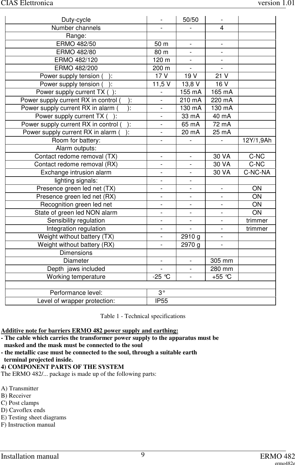
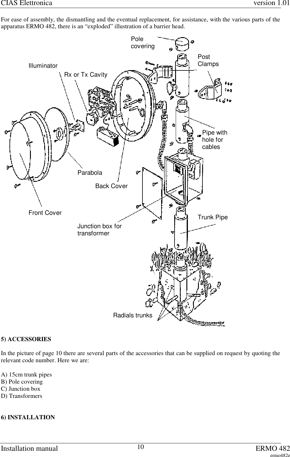
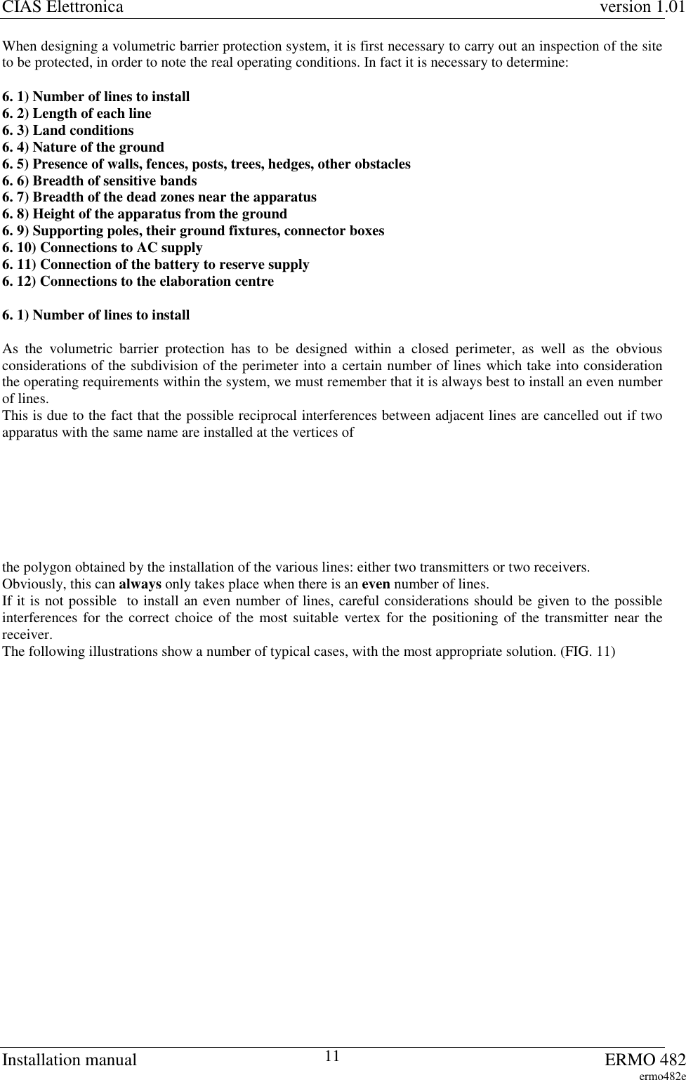
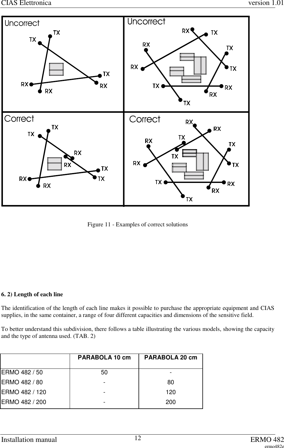
CIAS Elettronica S R L ERMO-482 User Manual INSTALLATION MANUAL
CIAS Elettronica S.R.L. INSTALLATION MANUAL
UserManual.wiki
>
CIAS Elettronica S R L
>
ERMO 482 User Manual
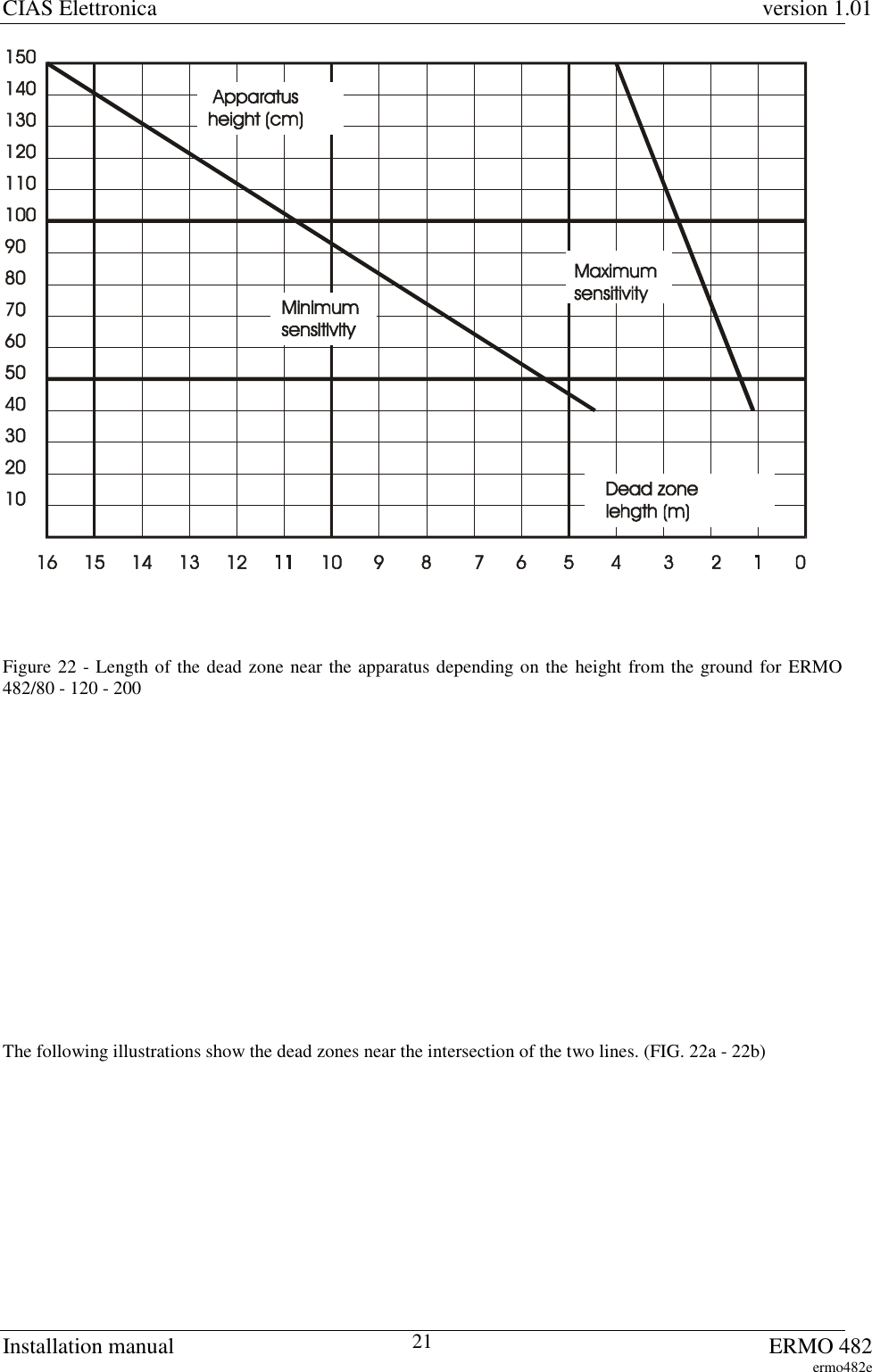
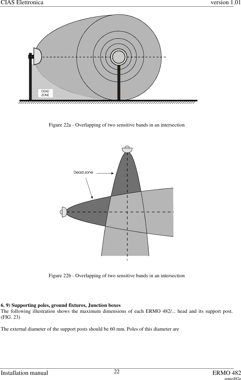
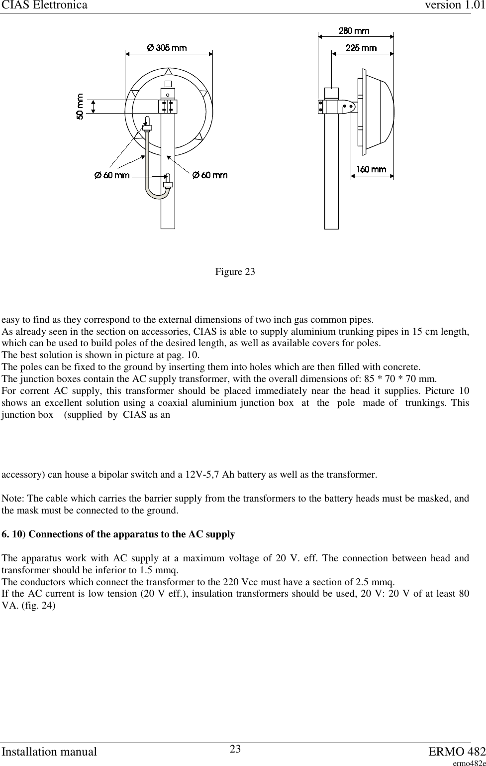
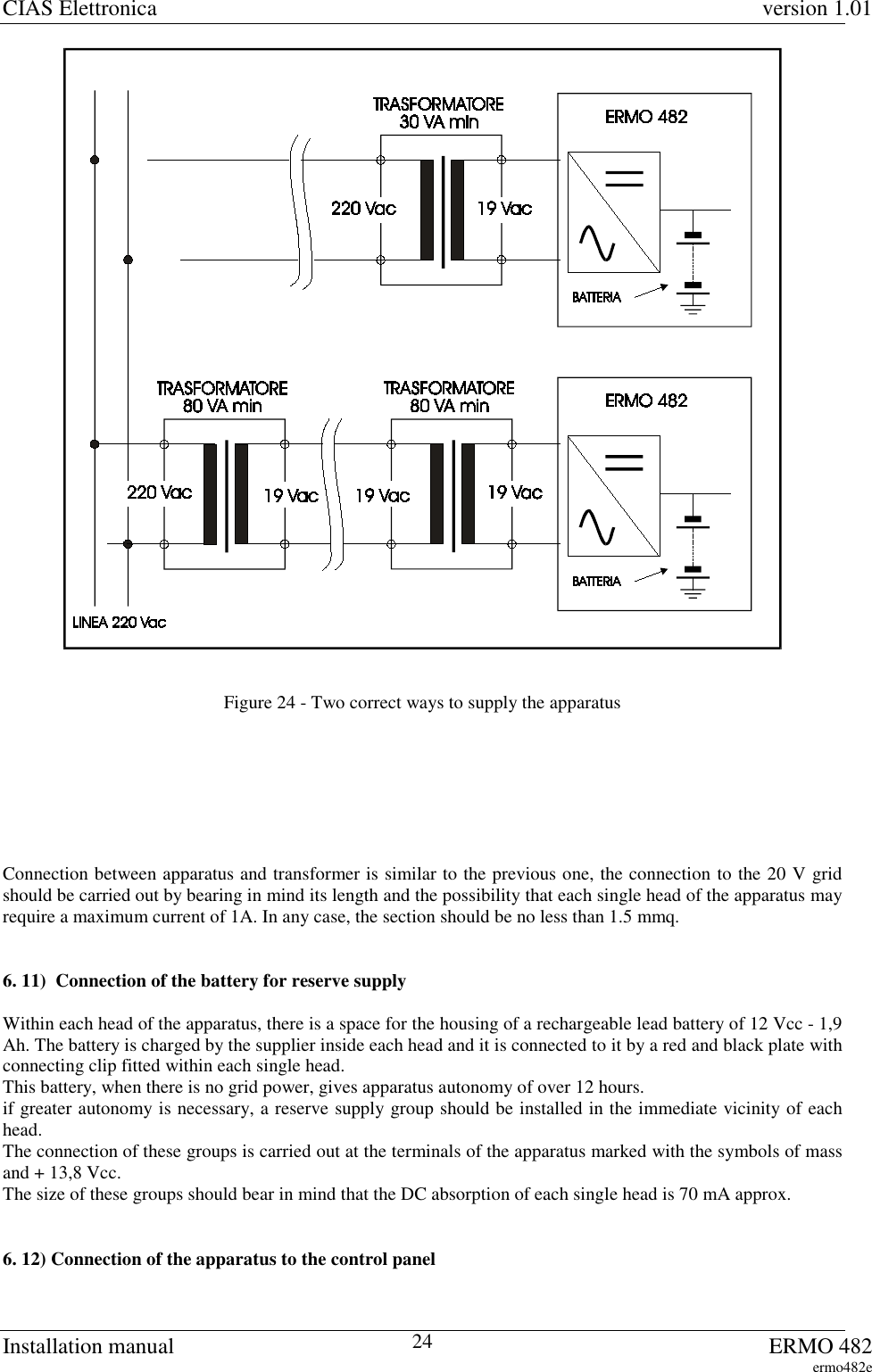
INSTALLATION MANUAL
Navigation menu
Upload a User Manual
Namespaces
Wiki Guide
HTML
PDF
Info
Views
User Manual
Discussion / Help
Navigation