CIAS Elettronica S R L ERMO-482X-PRO Microwave Barrier User Manual Man ERMO482xPro Ed5 0 pe USA
CIAS Elettronica S.R.L. Microwave Barrier Man ERMO482xPro Ed5 0 pe USA
User Manual

ERMO 482x PRO
Barriera a Microonde
per protezioni esterne
Manuale di Installazione
External Microwave Protection
Barrier
Installation Handbook
Edizione / Edition 5.0

© CIAS Elettronica S.r.l. Ed. 5.0
Manuale di Installazione Pagina 1 di 59 ERMO 482X PRO
11INDICE
1. DESCRIZIONE.......................................................................................................................................................................3
1.1 DESCRIZIONE ......................................................................................................................................................................3
1.2 SCHEMA A BLOCCHI ............................................................................................................................................................4
2. INSTALLAZIONE..................................................................................................................................................................5
2.1 INFORMAZIONI PRELIMINARI...............................................................................................................................................5
2.2 NUMERO DI TRATTE............................................................................................................................................................5
2.3 CONDIZIONI DEL TERRENO..................................................................................................................................................6
2.4 PRESENZA DI OSTACOLI......................................................................................................................................................6
2.5 AMPIEZZA DEI FASCI SENSIBILI...........................................................................................................................................7
2.6 LUNGHEZZA DELLE ZONE MORTE IN PROSSIMITÀ DEGLI APPARATI.....................................................................................8
3. COLLEGAMENTI .................................................................................................................................................................9
3.1 MORSETTIERE, CONNETTORI E FUNZIONALITÀ DEI CIRCUITI...............................................................................................9
3.1.1 Circuito Trasmettitore...............................................................................................................................................9
3.1.2 Circuito Ricevitore ...........................................................................................................................................12
3.2 COLLEGAMENTO ALL’ALIMENTAZIONE PRINCIPALE.........................................................................................................15
3.2.1 Collegamento all’Alimentazione.............................................................................................................................15
3.2.2 Collegamento all’Alimentazione di Riserva............................................................................................................15
3.3 COLLEGAMENTO ALLA CENTRALE....................................................................................................................................16
3.3.1 Contatti di allarme: Allarme, Guasto, Manomissione............................................................................................16
3.3.2 Connessioni per Sincronismo..................................................................................................................................17
3.3.3 Connessioni per Stand-by .......................................................................................................................................17
3.3.4 Connessioni per Test...............................................................................................................................................17
3.3.5 Connessioni per Linea Bilanciata...........................................................................................................................17
3.4 LINEA SERIALE RS-485....................................................................................................................................................19
3.4.1 Interfaccia Linea Seriale RS-485 / 232...................................................................................................................19
3.4.2 Connessioni per Linea Seriale RS-485 ...................................................................................................................19
3.4.3 Configurazione Rete e Rigeneratori di segnale ......................................................................................................19
3.5 COLLEGAMENTO DA ACCESSO REMOTO ...........................................................................................................................20
4. ALLINEAMENTO E VERIFICA.......................................................................................................................................21
4.1 ALLINEAMENTO E VERIFICA .............................................................................................................................................21
4.1.1 Operazioni sul Trasmettitore ..................................................................................................................................21
4.1.2 Operazioni sul Ricevitore........................................................................................................................................22
4.2 ALLINEAMENTO E VERIFICA CON SOFTWARE....................................................................................................................26
5. MANUTENZIONE E ASSISTENZA..................................................................................................................................27
5.1 RICERCA GUASTI ..............................................................................................................................................................27
5.2 KIT ASSISTENZA...............................................................................................................................................................27
6. CARATTERISTICHE..........................................................................................................................................................28
6.1 CARATTERISTICHE TECNICHE ...........................................................................................................................................28
6.2 CARATTERISTICHE FUNZIONALI.......................................................................................................................................29
APPENDICE A..........................................................................................................................................................................30

© CIAS Elettronica S.r.l. Ed. 5.0
Manuale di Installazione Pagina 2 di 59 ERMO 482X PRO
INDEX
1. DESCRIPTION.....................................................................................................................................................................32
1.1 DESCRIPTION ....................................................................................................................................................................32
1.2 BLOCK DIAGRAM...............................................................................................................................................................33
2. INSTALLATION..................................................................................................................................................................34
2.1 PRELIMINARY INFORMATION ............................................................................................................................................34
2.2 NUMBER OF SECTIONS ......................................................................................................................................................34
2.3 GROUND CONDITIONS .......................................................................................................................................................35
2.4 PRESENCE OF OBSTACLES.................................................................................................................................................35
2.5 AMPLITUDE OF THE SENSITIVE BEAM ...............................................................................................................................36
2.6 LENGTH OF THE DEAD ZONES NEAR THE EQUIPMENT........................................................................................................37
3.1 TERMINAL BLOCKS, CONNECTORS AND CIRCUITS FUNCTIONS .........................................................................................38
3.1.1 Transmitter Circuit .................................................................................................................................................38
3.1.2 Receiver Circuit ......................................................................................................................................................41
3.2 EQUIPMENT CONNECTION TO THE POWER SUPPLY............................................................................................................44
3.2.1 Connection to the Power Supply.............................................................................................................................44
3.2.2 Connection of stand-by Battery...............................................................................................................................44
3.3 CONNECTION TO THE CONTROL PANEL.............................................................................................................................45
3.3.1 Alarm contacts: Alarm, Tamper, Fault...................................................................................................................45
3.3.2 Synchronism connection .........................................................................................................................................46
3.3.3 Stand-by connection................................................................................................................................................46
3.3.4 Test connection .......................................................................................................................................................46
3.3.5 Balanced Line connection.......................................................................................................................................46
3.4 SERIAL LINE RS-485.........................................................................................................................................................48
3.4.1 RS - 485 / 232 Network Connection Interface ........................................................................................................48
3.4.2 RS -485 Serial Line connections.............................................................................................................................48
3.4.3 Network Configuration and Signal Repeaters ........................................................................................................48
3.5 REMOTE CONNECTION ......................................................................................................................................................49
4. ADJUSTMENT AND TESTING.........................................................................................................................................50
4.1 ADJUSTMENT AND TESTING ..............................................................................................................................................50
4.1.1 Transmitter Setting-up ............................................................................................................................................50
4.1.2 Receiver Setting-up .................................................................................................................................................51
4.2 ADJUSTMENT AND TESTING WITH SOFTWARE...................................................................................................................54
5. MAINTENANCE AND ASSISTANCE ..............................................................................................................................55
5.1 TROUBLESHOOTING ..........................................................................................................................................................55
5.2 MAINTENANCE KITS..........................................................................................................................................................55
6. CHARACTERISTICS..........................................................................................................................................................56
6.1 TECHNICAL CHARACTERISTICS ..........................................................................................................................................56
6.2 FUNCTIONAL CHARACTERISTICS.......................................................................................................................................57
APPENDICE A...........................................................................................................................................................................58
© CIAS Elettronica S.r.l. Ed. 5.0
Manuale di Installazione Pagina 3 di 59 ERMO 482X PRO
1. DESCRIZIONE
1.1 Descrizione
ERMO 482X PRO è la barriera digitale a microonde di CIAS per protezione volumetrica interna
ed esterna. Il suddetto sistema è in grado di rilevare la presenza di un corpo che si muove
all’interno di un campo sensibile instauratosi tra il Trasmettitore (TX) e il Ricevitore (RX).
Il segnale ricevuto viene analizzato digitalmente, attraverso i metodi della logica Fuzzy,
permettendo di raggiungere eccellenti prestazioni nella rilevazione e la diminuzione dei Falsi
Allarmi.
Ermo 482X PRO è disponibile con le seguenti portate:
- ERMO 482X PRO / 50 Portata 50 metri
- ERMO 482X PRO / 80 Portata 80 metri
- ERMO 482X PRO / 120 Portata 120 metri
- ERMO 482X PRO / 200 Portata 200 metri
© CIAS Elettronica S.r.l. Ed. 5.0
Manuale di Installazione Pagina 4 di 59 ERMO 482X PRO
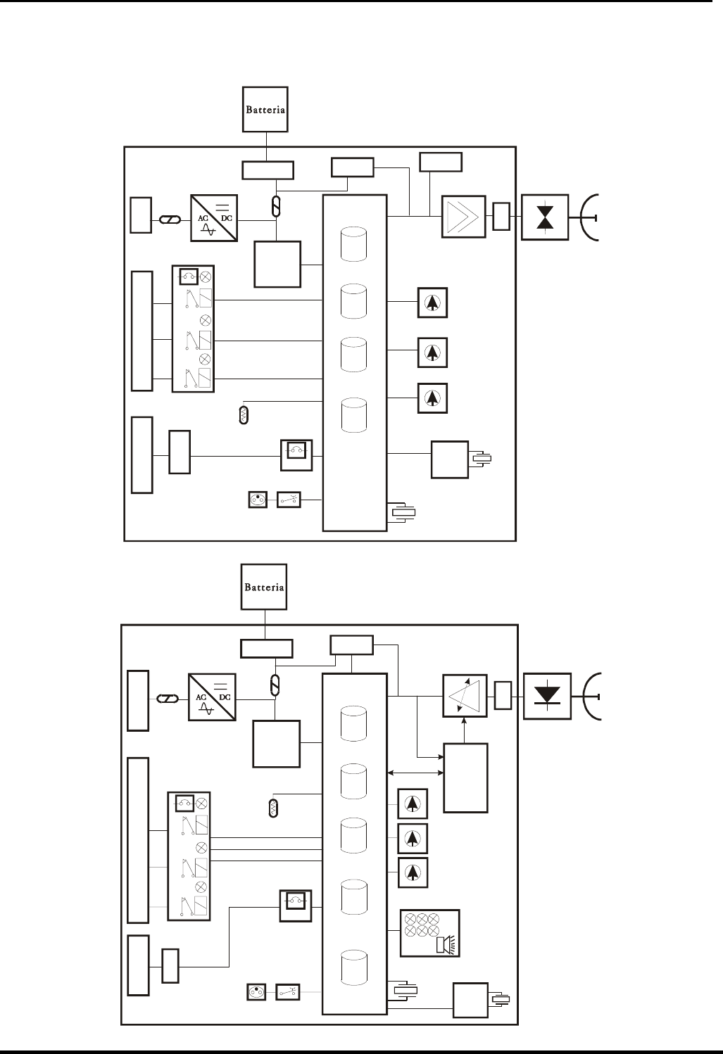
1.2 Schema a blocchi
Negli schemi a blocchi che seguono sono rappresentati i gruppi funzionali della testa
Trasmittente e Ricevente della barriera Ermo 482X Pro.
Ms4
J1
PARAMETRI
DEFAULT
PARAMETRI
LAVORO
STORICO
EVENTI
PASSWORDS
J3
Ms1
F2 F3
OSCILLATORE
MW
10.525 GHz ANTENNA
MW
A
MPLIFICATORE
Jp5
J5
Amp1
CPU
PREAMPLIFICATORE
E SELETTORE
DI SINCRONISMO
SELETTORE CANALE
DI MODULAZIONE
INTERFACCIA
RS-485
INTERFACCIA
DI ALLARME
A RELE'
MORSETTIERA
PRINCIPALE
A
LIMENTATORE
E CARICA BATTERIA
MORSETTIERE
PER CARICA BATTERIA
CONNETTORE PER
OSCILLATORE A MW
T°
SONDA DI
TEMPERATURA
PROTEZIONI PER
APERTURA E DISORIENTAMENTO
CONTENITORE
CONNETTORE PER
STRUMENTO DI
TARATURA E
COLLAUDO
STC-95
0
1
2
3
4
5
6
7
8
9
A
B
C
D
E
F
0
1
2
3
4
5
6
7
8
9
0
1
2
3
4
5
6
7
8
9
COMMUTATORE
SELEZIONE
N° TRATTA (DECINE)
COMMUTATORE
SELEZIONE
N° TRATTA (UNITA’)
RL
GUA
RL
MAN
RL
ALL
CONNETTORE E
MORSETTIERA
PER LA CONNESSIONE
DELLA LINEA SERIALE
REGOLATORE
DI TENSIONE
+ 5 Vdc
Sw1
Sw3
Sw2
Ms5
J6
Ms2
Ms3
RTC
32768 Hz
4.00 MHz
Schema a blocchi Ermo 482X Pro Trasmettitore
Ms3
J1
PARAMETRI
DEFAULT
PARAMETRI
LAVORO
STORICO
EVENTI
MONITOR
EVENTI
A
NALOGICI
PASSWORDS
J3
Ms1
F2 F3
DETECTOR
MW
10.525 GHz ANTENNA
MW
A
MPLIFICATORE
REGOLATO
Jp5
J4
Amp1
Jp4
CPU
INTERFACCIA
RS-485
INTERFACCIA
DI ALLARME
A RELE'
ALIMENTATORE
E CARICA BATTERIA
MORSETTIERE
PER CARICA BATTERIA CONNETTORE PER
DETECTOR A MW
RL
GUA
RL
MAN
T°
SONDA DI
TEMPERATURA
PROTEZIONI PER
APERTURA E DISORIENTAMENTO
CONTENITORE
CONNETTORE PER
STRUMENTO DI
TARATURA E
COLLAUDO
STC-95
REGOLATORE
A
UTOMATICO
DI
GUADAGNO
DIGITALE
RL
ALL
INTERFACCIA DI
PUNTAMENTO
E DI
WALK TEST
0
1
2
3
4
5
6
7
8
9
0
1
2
3
4
5
6
7
8
9
SELETTORI PER
FUNZIONI
0
1
2
3
4
5
6
7
8
9
SELETTORE
REGOLAZIONI
REGOLATORE
DI TENSIONE
+ 5 Vdc
Sw1
Sw2
Sw3
Ms2
RTC
J5
Ms4
32768 Hz
11.0592 MHz
CONNETTORE E
MORSETTIERA
PER LA CONNESSIONE
DELLA LINEA SERIALE
Schema a blocchi Ermo 482X Pro Ricevitore
© CIAS Elettronica S.r.l. Ed. 5.0
Manuale di Installazione Pagina 5 di 59 ERMO 482X PRO
2. INSTALLAZIONE
2.1 Informazioni preliminari
La diversificazione in vari modelli della barriera Ermo 482x PRO permette di ottimizzare
l’installazione in base alle esigenze dell’utente.
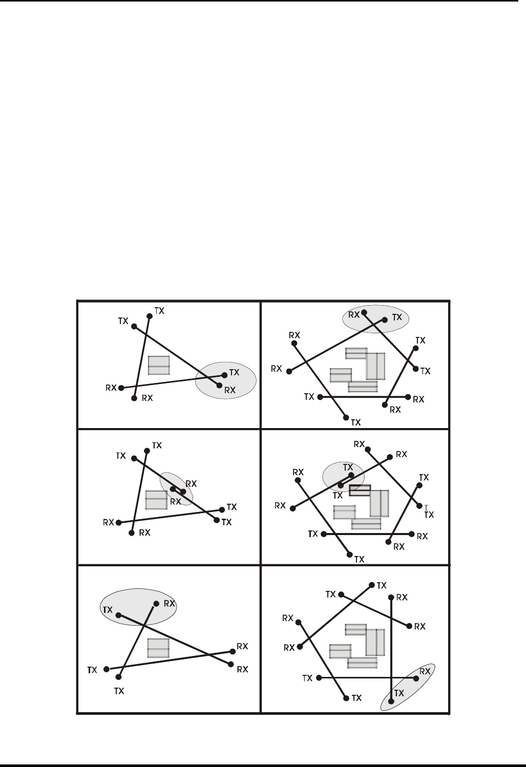
2.2 Numero di Tratte
Dovendo progettare la protezione con barriere volumetriche di un perimetro chiuso, oltre alle
normali considerazioni di suddivisione del perimetro in un certo numero di tratte che tengano
conto delle necessità gestionali dell'intero impianto, occorre ricordare che è sempre preferibile
installare un numero di tratte pari. Questa considerazione è legata al fatto che le possibili
interferenze reciproche, tra tratte contigue vengono annullate nel caso in cui ai vertici (Incroci)
del poligono risultante dall’installazione stessa, vengano installati due rivelatori aventi lo stesso
nome, cioè due trasmettitori o due ricevitori. E' evidente che ciò può avvenire solo nel caso che
il numero delle tratte sia pari. Qualora non fosse possibile disporne in numero pari, occorrerà
fare alcune attente considerazioni sulle possibili interferenze in modo che possa essere
correttamente scelto il vertice più opportuno dove collocare il Trasmettitore vicino al Ricevitore,
alcuni esempi sono illustrati in figura 1.
CORRETTO CORRETTO
ERRATO ERRATO
CORRETTO CORRETTO
Figura 1

© CIAS Elettronica S.r.l. Ed. 5.0
Manuale di Installazione Pagina 6 di 59 ERMO 482X PRO
2.3 Condizioni del Terreno
E' sconsigliabile installare l'apparato lungo tratti dove vi siano: erba alta (maggiore di 10 cm),
stagni, corsi d'acqua in senso longitudinale ed in generale tutti quei tipi di terreni la cui
conformazione sia rapidamente variabile.
2.4 Presenza di Ostacoli
Le recinzioni se metalliche e pertanto molto riflettenti, possono causare diversi problemi di
riflessione della microonda, è quindi necessario adottare alcuni accorgimenti:
- la recinzione deve essere accuratamente fissata, in modo che il vento non ne provochi il
movimento;
- dove possibile la tratta non deve essere installata in parallelo alla recinzione, è
necessario creare un angolo rispetto ad essa;
- nel caso in cui il fascio sensibile debba essere delimitato lateralmente da due reti
metalliche, è consigliabile che il corridoio tra esse non sia inferiore ai 5 m. in quanto il
loro movimento potrebbe creare dei disturbi; in caso contrario contattare l’assistenza
tecnica CIAS
- recinzioni metalliche poste dietro gli apparati possono provocare talvolta distorsioni del
fascio sensibile e quindi dare luogo a falsi allarmi.
Gli alberi, le siepi, i cespugli, la vegetazione in genere richiede una grand’attenzione qualora
ve ne sia in prossimità o entro i fasci di protezione.
Questi ostacoli sono elementi variabili sia come dimensione che come posizione, possono infatti
crescere ed essere mossi dal vento.
Figura 2
Pertanto è sconsigliabile tollerare la presenza di detti ostacoli entro le tratte di protezione.
E’ possibile tollerarne la presenza solo a patto che la loro crescita venga limitata mediante una
metodica manutenzione e che il loro movimento venga inibito mediante barriere di
contenimento. All’interno del fascio di protezione, è altresì tollerabile la presenza di tubi, pali ed
Ostacoli vari (illuminazione, camini, ecc) purché non presentino dimensioni eccessive all’interno
dei lobi di protezione. Questi infatti sono la causa di Zone d’Ombra non protette e di Zone di
Ipersensibilità, fonti di falsi allarmi.
© CIAS Elettronica S.r.l. Ed. 5.0
Manuale di Installazione Pagina 7 di 59 ERMO 482X PRO
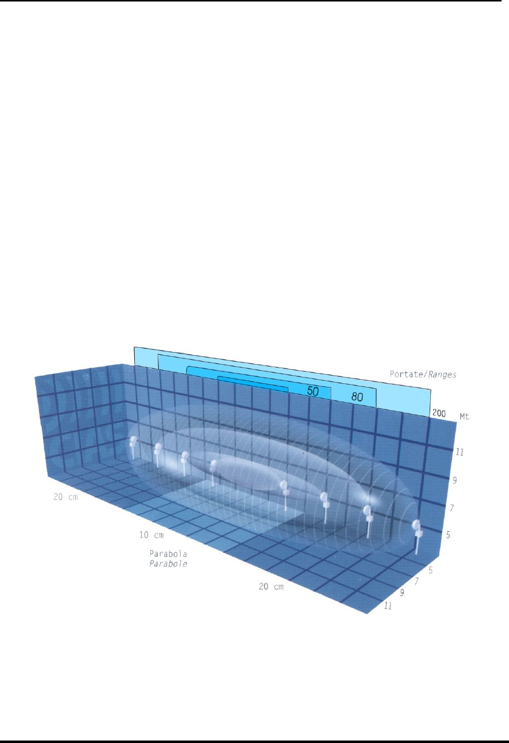
2.5 Ampiezza dei Fasci Sensibili
L'ampiezza del Campo Sensibile è in funzione sia del tipo di antenna impiegata, sia della
distanza tra Trasmettitore e Ricevitore, sia dalla regolazione di sensibilità impostata.
Le figure seguenti ci forniscono il diametro a metà tratta del Fascio Sensibile, in funzione della
lunghezza della tratta, nel caso di sensibilità massima e minima per i diversi modelli di
apparecchio impiegati.
Diametro
a metà tratta (m)
Sensibilità
massima
Sensibilità
minima
lunghezza
della tratta (m)
Figura 3 Diametro della zona sensibile a metà tratta per ERMOX 482/ 50
Diametro a
metà tratta (m) Sensibilità
massima
Sensibilità
minima
Lunghezza
della tratta (m)
Figura 4 Diametro della zona sensibile a metà tratta per ERMOX 482/ 80-120-200
Nota: è necessario ricordare che per l’apparato ERMO 482 X, la regolazione di sensibilità deve
essere presa in considerazione per ricavare la dimensione dei fasci sensibili a metà della
tratta. Quanto più alte sono le soglie di preallarme e di allarme, tanto più bassa è la
sensibilità e viceversa.
È inoltre importante ricordare che la soglia di preallarme determina il livello di inizio
elaborazione, cioè tutti i segnali che stanno al di sotto di tale soglia, sono considerati disturbo o
rumore. Tutti i segnali che superano questa soglia, danno luogo alla elaborazione del segnale
secondo le regole “Fuzzy” previste. Se, dopo aver superato la soglia di preallarme, il segnale di
intrusione resta per circa 40 sec tra la medesima e la soglia di allarme viene generato un evento
di preallarme, e si ha l’attivazione del relè di allarme.
Le soglie di preallarme, di allarme e quindi la sensibilità, sono regolabili sia mediante i dispositivi
integrati a bordo di ciascuna unità ricevente sia mediante il Software MWATEST. Le
impostazioni di default sono relative ad una sensibilità media adatta alla gran parte dei casi
pratici.
© CIAS Elettronica S.r.l. Ed. 5.0
Manuale di Installazione Pagina 8 di 59 ERMO 482X PRO
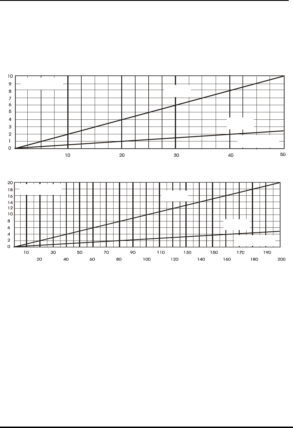
2.6 Lunghezza delle Zone Morte in prossimità degli apparati
La lunghezza delle Zone Morte in prossimità degli apparati è in funzione sia della distanza
dell'apparato stesso dal suolo, sia della sensibilità impostata sul Ricevitore, sia del tipo di
antenna impiegata (figure 5-6). L’Altezza consigliata per installazioni standard è di 80 cm
circa, compatibilmente con le esigenze impiantistiche. La misura è da considerarsi tra il suolo e
il centro dell'apparecchio. Con una sensibilità media, la distanza minima consigliata per
effettuare l’Incrocio è di 5 m per le barriere da 80-120-200 m e di 3,5 m per le barriere da
50 m
Sensibilità
Massima
Sensibilità
Minima
Lungh ezza della
Zona Morta (m)
Altezza dal Suolo
de gli A pparati (c m )
Figura 5 Lunghezza della zona morta in prossimità degli apparati in funzione dell’altezza dal
centro degli stessi al suolo per ERMO 482x PRO. 50
Lunghezza della
zona morta (m)
Sensibilità
minima
Sensibilità
massima
A
ltezza dal suolo
degli apparati (cm)
Figura 6 Lunghezza della zona morta in prossimità degli apparati in funzione dell’altezza dal
centro degli stessi al suolo per ERMO 482x PRO. 80-120-200
5 M
80-85 cm
Figura 7 - Sovrapposizione di due fasci sensibili in un incrocio-

© CIAS Elettronica S.r.l. Ed. 5.0
Manuale di Installazione Pagina 9 di 59 ERMO 482X PRO
3. COLLEGAMENTI
3.1 Morsettiere, connettori e Funzionalità dei Circuiti
3.1.1 Circuito Trasmettitore
AMP1
J3
MS1 MS2
S1
SW2
SW3
SW1
Jp5
Rete
Jp6
J1
Jp1
OUTSYNCIN
MS 4
MS
5
21 12
11
223
3445678910
ING
GND
TEST
ST.BY
GTS2
GTS1
PT 2
PT 1
ALL2
ALL1
L0
LH
GND1
13,8V
Jp4
1
2
MS 3
D7D8 D9 D15
1
1
Batteria
BackUp
Figura 8 Disposizione topografica dei componenti nel circuito Tx
Nelle seguenti tabelle sono indicate le funzioni delle morsettiere presenti sulla scheda ERMO
482x PRO TX:
MORSETTIERA MS2 TRASMETTITORE
Mors Simbolo Funzione
1 19 V~ Ingresso Tensione d’Alimentazione (19 V~) o (24V )
2 19 V~ Ingresso Tensione d’Alimentazione (19 V~) o (24V )
MORSETTIERA MS4 TRASMETTITORE
Mors
.
Simbolo Funzione
1 ALL 1 Contatto Relè di Allarme (C)
2 ALL 2 Contatto Relè di Allarme (NC)
3 PT 1 Contatto Relè di Manomissione (C)+ Ampolla (AMP1)
4 PT 2 Contatto Relè di Manomissione (NC)+ Ampolla (AMP1)
5 GTS 1 Contatto Relè di Guasto (C)
6 GTS 2 Contatto Relè di Guasto (NC)
7 STBY Ingresso Ausiliario per Comando Stand-By(Norm. Aperto da GND)
8 TEST Ingresso Ausiliario per Comando TEST (Norm. Aperto da GND)
9 GND Uscita Ausiliaria di Massa
10 ING Ingresso della linea Bilanciata per rivelatore esterno

© CIAS Elettronica S.r.l. Ed. 5.0
Manuale di Installazione Pagina 10 di 59 ERMO 482X PRO
MORSETTIERA MS5 TRASMETTITORE
Mors Simbolo Funzione
1 +13,8 Alimentazione (13,8 V ) convertitore interfaccia RS-485/232
2 GND 1 Massa per Dati e per Alimentazione interfaccia RS-485/232
3 LH Linea Alta per RS 485
4 LO Linea Bassa per RS 485
MORSETTIERA MS3 TRASMETTITORE
Mors Simbolo Funzione
1 GND 1 Negativo per collegamento cavo di sincronismo
2 SYNC Uscita/Ingresso del sincronismo, per Tx Master/Slave
CONNETTORE J1 TRASMETTITORE
connettore per oscillatore a microonde (DRO)
Mors Simbolo Funzione
1 GND Collegamento di Massa per Oscillatore a MW
2 DRO Collegamento Frequenza Modulante per Oscillatore a MW
3 GND Collegamento di Massa per Oscillatore a MW
CONNETTORE J3 TRASMETTITORE
Connettore a 16 pin per misure ( Strumento Stc 95 )
Mors Simbolo Funzione
1/3 N.C. Non Connesso
4 GND Massa
5 N.C. Non Connesso
6 +13,8 Tensione di Alimentazione (13,8 V )
7/11 N.C. Non Connesso
12 +5V Alimentazione interna (5 V )
13 OSC Misura Funzionamento Oscillatore (+ 4V = OK)
14/15 N.C. Non Connesso
16 +8V Alimentazione interna (8 V )
CONNETTORE J5 TRASMETTITORE
Connettore per microinterruttore apertura Radome
Mors Simbolo Funzione
1 GND Collegamento di Massa per Tamper
2 ING Ingresso Tamper
3 GND Collegamento di Massa per Tamper
MORSETTIERA MS1 TRASMETTITORE
Mors Simbolo Funzione
1 13,8V Positivo per collegamento Batteria tampone (+13,8V )
2 GND 1 Negativo per collegamento Batteria tampone

© CIAS Elettronica S.r.l. Ed. 5.0
Manuale di Installazione Pagina 11 di 59 ERMO 482X PRO
CONNETTORE J6 TRASMETTITORE
Connettore 10 pin Linea Seriale per Software di gestione
Mors Simbolo Funzione
1/2 N.C. Non Connesso
3 +13,8 Alimentazione (13,8 V ) convertitore interfaccia RS-485/232
4 N.C. Non Connesso
5 LO Linea Bassa per RS 485
6 N.C Non Connesso
7 LH Linea Alta per RS 485
8 N.C. Non Connesso
9 GND Massa
10 N.C. Non Connesso
SELETTORE CANALI DEL TRASMETTITORE
N° Simbolo Funzione
1 SW1 Commutatore per la Selezione dei Canali di Modulazione
SELETTORI NUMERO TRATTA TRASMETTITORE
N° Simbolo Funzione
2 SW2 Commutatore di Selezione del numero tratta (unità)
3 SW3 Commutatore di Selezione del numero tratta (decine)
FUSIBILI DEL TRASMETTITORE
N° Simbolo Funzione
1 F1 Fusibile protezione per 13,8 V (T2A-250V ritardato)
2 F2 Fusibile protezione per 19 V~ (T2A-250V ritardato)
3 F3 Fusibile protezione per Batteria 13,8 V (T2A-250V ritardato)
LEDS DEL TRASMETTITORE
N° Simbolo Funzione Default
7 D7 Indicazione Guasto. ON
8 D8 Indicazione Manomissione. ON
9 D9 Indicazione Allarme. ON
15 D15 Indicazione Presenza Rete ON
JUMPERS DEL TRASMETTITORE
N° Simbolo Funzione Default
1 Jp1 Modulazione Interna (Tx-Master,Sync-Out) o
Esterna (Tx-Slave,Sync-In) OUT
4 Jp4 Esclusione led di indicazione guasto, allarme e
manomissione, (Jp4 posizione 2/3 = led esclusi) ON
5 Jp5 Terminazione Linea Seriale (Jp5 posizione 2/3 =
terminazione inserita) OFF
6 Jp6 Abilitazione / Disabilitazione Ingresso linea
bilanciata (Chiuso = ingresso disabilitato) OFF
© CIAS Elettronica S.r.l. Ed. 5.0
Manuale di Installazione Pagina 12 di 59 ERMO 482X PRO
3.1.2 Circuito Ricevitore
AMP1
MS1 MS2
J3
J4
JP5
SW3 SW2
SW1
S3
D 17
S 1
J1
11
223
3445678910
ING
GND
TEST
ST.BY
GTS2
GTS1
PT 2
PT 1
ALL2
ALL1
L0
LH
GND1
13,8V
GND1
12
+13,8 V
12
19V~
19V~
D7D9 D6 D8
D10D11
MS3 MS4
1
1
Jp4
Batteria
BackUp
1
Jp3
Figura 9 Disposizione topografica dei componenti nel circuito Rx
Nelle seguenti tabelle sono indicate le funzioni delle morsettiere presenti sulla scheda ERMO
482x PRO RX:
MORSETTIERA MS2 RICEVITORE
Mors Simbolo Funzione
1 19 V~ Ingresso Tensione di Alimentazione (19 V~) o (24V )
2 19 V~ Ingresso Tensione di Alimentazione (19 V~) o (24V )
MORSETTIERA MS3 RICEVITORE
Mors Simbolo Funzione
1 ALL 1 Contatto Relè di Allarme (C)
2 ALL 2 Contatto Relè di Allarme (NC)
3 PT 1 Contatto Relè di Manomissione (C)+ Ampolla (AMP1)
4 PT 2 Contatto Relè di Manomissione (NC)+ Ampolla (AMP1)
5 GTS 1 Contatto Relè di Guasto (C)
6 GTS 2 Contatto Relè di Guasto (NC)
7 ST BY Ingresso Ausiliario Comando Stand-By (Norm Aperto da GND)
8 TEST Ingresso Ausiliario Comando TEST (Norm. Aperto da GND)
9 GND Uscita Ausiliaria di Massa
10 ING Ingresso della linea Bilanciata per rivelatore esterno
MORSETTIERA MS1 RICEVITORE
Mors Simbolo Funzione
1 +13,8V Positivo per collegamento Batteria tampone (+13,8V )
2 GND 1 Negativo per collegamento Batteria tampone

© CIAS Elettronica S.r.l. Ed. 5.0
Manuale di Installazione Pagina 13 di 59 ERMO 482X PRO
MORSETTIERA MS4 RICEVITORE
Mors Simbolo Funzione
1 +13,8V Alimentazione (13,8 V ) convertitore interfaccia RS-485/232
2 GND 1 Uscita ausiliaria Massa per Dati per interfaccia RS-485/232
3 LH Linea Alta per RS 485
4 LO Linea Bassa per RS 485
CONNETTORE J1 RICEVITORE
connettore per rivelatore a microonde
Mors Simbolo Funzione
1 GND Collegamento di Massa per Rivelatore a Microonde
2 DET Collegamento per Rivelatore a Microonde (Detector)
3 GND Collegamento di Massa per Rivelatore a Microonde
CONNETTORE J3 RICEVITORE
Connettore 16 pin per misure. ( Strumento Stc 95 )
Mors Simbolo Funzione
1/3 N.C. Non Connesso
4 GND Massa
5 N.C Non Connesso
6 +13,8 Tensione di Alimentazione (13,8 V )
7/8 N.C Non Connesso
9 0,2V. Segnale Rivelato 200 mVpp
10/11 N.C. Non Connesso
12 +5V Alimentazione interna (5 V )
13 N.C Non Connesso
14 VRAG Tensione del Regolatore Automatico di Guadagno
15/16 N.C. Non Connesso
CONNETTORE J4 RICEVITORE
Connettore per microinterruttore apertura Radome “Tamper”
Mors Simbolo Funzione
1 GND Collegamento di Massa per Tamper
2 ING Ingresso Tamper
3 GND Collegamento di Massa per Tamper
CONNETTORE J5 RICEVITORE
Connettore 10 pin Linea Seriale per Software di gestione
Mors Simbolo Funzione
1/2 N.C. Non Connesso
3 +13,8 Alimentazione (13,8 V ) convertitore interfaccia RS-485/232
4 N.C. Non Connesso
5 LO Linea Bassa per RS 485
6 N.C Non Connesso
7 LH Linea Alta per RS 485
8 N.C. Non Connesso
9 GND Massa
10 N.C. Non Connesso

© CIAS Elettronica S.r.l. Ed. 5.0
Manuale di Installazione Pagina 14 di 59 ERMO 482X PRO
FUSIBILI DEL RICEVITORE
N° Simbolo Funzione
1 F1 Fusibile protezione per 13,8 V (T2A-250V ritardato)
2 F2 Fusibile protezione per 19 V~ (T2A-250V ritardato)
3 F3 Fusibile protezione per Batteria 13,8 V (T2A-250V ritardato)
JUMPERS DEL RICEVITORE
N° Simbolo Funzione Default
3 Jp3 Esclusione Batteria Back-Up dati e parametri (Jp
posizione 2/3 = batteria collegata cioè ON) ON
4 Jp4 Esclusione leds da D6 a D11(Jp posizione 2/3 =
Leds On) ON
5 Jp5 Terminazione Linea Seriale (Jp posizione 2/3 =
terminazione inserita) OFF
LEDS DEL RICEVITORE
N° Simbolo Funzione Default
6 D6 Indica Guasto + Allineamento/regolazioni ON
7 D7 Indica Manomissione + Allineamento/regolazioni ON
8 D8 Indica Allarme + Allineamento/regolazioni ON
9 D9 Funzioni Allineamento e Regolazione OFF
10 D10 Funzioni Allineamento e Regolazione OFF
11 D11 Funzioni Allineamento e Regolazione OFF
17 D17 Indica Presenza Rete ON
PULSANTE DI CONFERMA ALLINEAMENTO / REGOLAZIONI
N° Simbolo Funzione
1 S3 Attivazione/conferma scrittura/acquisizione fase di
allineamento/regolazione
SELETTORE DI FUNZIONI SUL RICEVITORE
N° Simbolo Funzione
1 SW1 Posizione 1 = Allineamento Barriera
Posizione 2 = Acquisizione Canale e valore di campo.
Posizione 3 = Lettura/scrittura soglia di preallarme.
Posizione 4 = Lettura/scrittura soglia di allarme + Walk-Test
Posizione 5 = Lettura/scrittura soglia di Mascheramento.
Posizione 6 = Lettura/scrittura soglia di preallarme sup (FSTD)
Posizione 7 = Lettura/scrittura soglia allarme superiore(FSTD)
Posizione 8 = Lettura/scrittura Numero Tratta.
Posizione 9 = Fine allineamento con linea bilanciata inclusa.
Posizione 0 = Fine allineamento con linea bilanciata esclusa.
SELETTORI LETTURA / SCRITTURA PARAMETRI E NUMERO
BARRIERA DEL RICEVITORE
N° Simbolo Funzione
2 SW2 Commutatore decimale per lettura o impostazione dei
parametri durante le fasi di allineamento (unità)
3 SW3 Commutatore decimale per lettura o impostazione dei
parametri durante le fasi di allineamento (decine)

© CIAS Elettronica S.r.l. Ed. 5.0
Manuale di Installazione Pagina 15 di 59 ERMO 482X PRO
3.2 Collegamento all’Alimentazione Principale
Gli apparati pur funzionando perfettamente in Corrente Continua a 13,8 V , è preferibile che
siano alimentati in Corrente Alternata alla tensione di 19 V~ oppure 24 V .
3.2.1 Collegamento all’Alimentazione
Il collegamento tra il trasformatore e la rete a 115 V~ dovrà essere effettuato con conduttori la
cui sezione sia di almeno 1,5 mm². Il cavo che porta l’alimentazione dal trasformatore
all’apparecchiatura deve risultare il più breve possibile,deve essere schermato e lo schermo
deve essere collegato a terra. I due conduttori devono essere collegati ai morsetti 1 e 2 della
morsettiera MS2 sia nel circuito Rx che nel Tx.
Il fusibile di protezione F2 è del tipo ritardato con una portata di 2 A (T2A)
Il trasformatore da utilizzare deve avere le seguenti caratteristiche:
• tensione primaria: 115 V~
• tensione secondaria: 19 V~
• potenza minima: 30 VA
N.B. utilizzare esclusivamente trasformatori di sicurezza certificati secondo le norme vigenti, ad
esempio EN 60950. Deve essere assicurato un ottimo collegamento a terra della carcassa
del trasformatore. Il collegamento del trasformatore alla rete 115 V~ deve essere
effettuato attraverso un idoneo dispositivo di sezionamento che abbia le seguenti
caratteristiche:
• bipolare con distanza minima tra i contatti di 3 mm
• previsto nell’impianto fisso
• facilmente accessibile
In ogni caso occorre attenersi scrupolosamente alle prescrizioni contenute nelle
leggi e normative vigenti in materia di installazioni fisse di apparati collegati
permanentemente alla rete di alimentazione come la Legge 46/90 e la Normativa CEI
64-8.
Se la barriera è alimentata solo in corrente continua (13,8 V ), per evitare che dopo 3 ore
dall’attivazione, sia prodotto un allarme di guasto per assenza rete, è necessario collegare
il positivo dell’alimentazione al morsetto 1 o 2 della morsettiera MS2 sia per il Ricevitore
che per il Trasmettitore.
3.2.2 Collegamento all’Alimentazione di Riserva
All’interno di ciascuna testa è previsto lo spazio per alloggiare una Batteria ricaricabile al
piombo da 12 V - 1.9 Ah (opzionale). La batteria è normalmente ricaricata dall’alimentatore
interno per mezzo dei due conduttori che devono essere collegati ai morsetti della morsettiera
MS1 sia nel circuito Rx che nel Tx. Il Fusibile di protezione, contro i sovraccarichi e/o la
inversione della batteria, è del tipo ritardato con una portata di 2A (T2A)
Questa batteria, in condizioni d’assenza rete, consente un’autonomia di circa 12 ore.
N.B. gli involucri delle batterie tampone utilizzate, devono avere una classe di autoestinguenza
HB o migliore ( Standard UL 94 ).

© CIAS Elettronica S.r.l. Ed. 5.0
Manuale di Installazione Pagina 16 di 59 ERMO 482X PRO
3.3 Collegamento alla Centrale
Le connessioni alla Centrale di elaborazione devono essere effettuate mediante cavi schermati.
3.3.1 Contatti di allarme: Allarme, Guasto, Manomissione
Le uscite degli apparati sono costituite da 3 contatti normalmente chiusi liberi da potenziale sia
sul Trasmettitore che sul Ricevitore per la segnalazione dei seguenti stati:
• ALLARME, GUASTO, MANOMISSIONE
Sono inoltre presenti 3 Ingressi per attuare le seguenti funzioni:
• Test (TX e RX)
• Stand-by (TX e RX)
• Sincronismo (solo TX)
I contatti di uscita per allarme, manomissione e guasto sia sul Trasmettitore sia sul Ricevitore,
sono costituiti da Relè statici con una portata di 100 mA max.
N.B. i contatti di Allarme, Manomissione e Guasto presentano, in stato di Vigilanza (contatto
chiuso), una resistenza di circa 40 Ohm. I contatti d’allarme, sono attivati, per i seguenti
motivi:
- RELE’ di ALLARME
1- Preallarme sul Ricevitore (Nota 1)
2- Allarme Intrusione su Ricevitore
3- Allarme mascheramento su Ricevitore
4- Allarme del rivelatore connesso sulla Linea Bilanciata Ausiliaria (TX e RX)
5- Risultato Positivo dell’esecuzione di una procedura di Test su Ricevitore
6- Segnale ricevuto insufficiente (V RAG >6,5V)
7- Allarme canale
- RELE’ di MANOMISSIONE
1- Rimozione del coperchio (Radome)
2- Sposizionamento Ampolla
3- Manomissione del rivelatore connesso sulla Linea Bilanciata Ausiliaria
4- Taglio della Linea Bilanciata Ausiliaria
5- Corto Circuito della Linea Bilanciata Ausiliaria
- RELE’ di GUASTO
1- Tensione di Batteria Bassa (< +11V )
2- Tensione di Batteria Alta (> +14.8V )
3- Temperatura Bassa (< -35°C interna)
4- Temperatura Alta (> +75°C interna)
5- Guasto del rivelatore connesso sulla Linea Bilanciata Ausiliaria
6- Guasto oscillatore BF (bassa frequenza) o RF (radio frequenza) circuito TX
7- Assenza rete per più di 3 ore continuative o guasto alimentatore
Nota 1: se il segnale di intrusione, dopo aver superato la soglia di preallarme, resta per 40 sec
circa, tra la medesima e la soglia di allarme viene generato un evento di preallarme, e si
ha l’attivazione del relè di allarme (si apre il contatto).

© CIAS Elettronica S.r.l. Ed. 5.0
Manuale di Installazione Pagina 17 di 59 ERMO 482X PRO
3.3.2 Connessioni per Sincronismo
Per effettuare il Sincronismo tra due Trasmettitori occorre connettere tra loro i morsetti 2
“SYNC” ed i morsetti 1 “GND1” della morsettiera MS3 dei due Trasmettitori.
È Inoltre necessario selezionare un Trasmettitore come “Master” e l’altro come “Slave”
mediante il ponticello Jp1.
• Con Jp1 in posizione “IN” il morsetto 2 di MS3 è il morsetto di ingresso per un
sincronismo che proviene dall’esterno, pertanto il Trasmettitore così predisposto è
“Slave”.
• Con Jp1 in posizione “OUT” il morsetto 2 di MS3 è il morsetto di uscita del segnale di
sincronismo che viene prodotto all’interno, pertanto il Trasmettitore così predisposto è
“Master”.
N.B. il cavo di connessione tra un trasmettitore e l’altro, deve essere il più breve possibile
(< 10 metri) e deve essere schermato con schermo collegato a terra. Per lunghezze del
cavo di sincronismo maggiori di 10 metri occorre utilizzare un circuito di ripetizione del
sincronismo (mod. SYNC 01).
3.3.3 Connessioni per Stand-by
Per attivare la funzione di Stand-by è necessario collegare a GND il morsetto 7 “STBY” di MS3
sul Ricevitore o il morsetto 7 “STBY” di MS4 sul Trasmettitore.
N.B. lo Stand-by non inibisce la funzionalità della barriera, ma disattiva la registrazione degli
eventi nel file storico (TX e RX) e nel file di monitor del ricevitore.
3.3.4 Connessioni per Test
La funzione di test viene attivata connettendo il morsetto 8 “TEST” della morsettiera MS4 del
circuito Trasmettitore a GND. Se la procedura di test è andata a buon fine dopo 10 sec si
attiverà il relè di allarme sul circuito Ricevitore.
N.B. nelle protezioni ad Alto Rischio è indispensabile che i rivelatori siano sottoposti con
adeguata periodicità al Test operativo. In questo modo la centrale di allarme sarà in grado
di riconoscere i tentativi di elusione.
3.3.5 Connessioni per Linea Bilanciata
Sia sul trasmettitore, che sul ricevitore è previsto un ingresso Bilanciato per collegare un
rivelatore esterno la cui attività è completamente controllata da ciascuna testa TX o RX.
L’attivazione di questa linea bilanciata avviene: sul trasmettitore togliendo il ponticello Jp6, e sul
ricevitore concludendo la procedura di installazione con il commutatore di funzione SW1 in
posizione 9 anziché 0. Le linee bilanciate vengono rese disponibili: sul trasmettitore, tra il
morsetto 10 (ING) ed il morsetto 9 (GND) della morsettiera MS4 e sul ricevitore, tra il morsetto
10 (ING) ed il morsetto 9 (GND) della morsettiera MS3.

© CIAS Elettronica S.r.l. Ed. 5.0
Manuale di Installazione Pagina 18 di 59 ERMO 482X PRO
Per ciascun rivelatore esterno possono essere gestiti gli stati di:
• riposo
• allarme
• manomissione
• guasto
Possono inoltre essere gestiti gli stati di:
• taglio Linea di collegamento tra rivelatore e testa (TX o RX)
• corto Circuito Linea di collegamento tra rivelatore e testa (TX o RX)
Per ottenere la gestione di tutti questi stati occorre realizzare una pesatura mediante resistori
collegati come nella seguente figura.
0- 0.5CORTO CIRCUITO
STATO
DELL’INGRESSO
TENSIONE DI INGRESSO
[V cc]
TAGLIO
GUASTO
MANOMISSIONE
ALLARME
RIPOSO 0.5 1 1.5
1.5 2 2.5
2.5 3 3.5
3.5 4 4.5
4.5 - 5
Min. Med. Max.
Nella tabella riportata sono indicati i valori di tensione che si localizzano sui morsetti di ingresso
della linea bilanciata per i vari stati del rivelatore esterno e della linea che lo collega alla testa
TX o RX. Questi valori possono essere letti anche mediante il SW MWA-TEST nella schermata
“Valori Analogici”, sia con un PC collegato localmente che attraverso una connessione remota.
AMP1
MS1 MS2
J2
J3
J4
JP5
SW3 SW2
SW1
S3
D 17
S 1
J1
11
223
3445678910
ING
GND
TEST
ST.BY
GTS2
GTS1
PT 2
PT 1
ALL2
ALL1
L0
LH
GND1
13,8V
GND1
12
+13,8 V
12
19V~
19V~
D7D9 D6 D8
D10D11
470
Ω
470
Ω
1K
1,5K
Ω
Ω
RIVELATORE ESTERNO
SCHEDA RICEVITORE
MS3 MS4

© CIAS Elettronica S.r.l. Ed. 5.0
Manuale di Installazione Pagina 19 di 59 ERMO 482X PRO
3.4 Linea Seriale RS-485
3.4.1 Interfaccia Linea Seriale RS-485 / 232
Sia il ricevitore che il trasmettitore della barriera ERMO 482x PRO, sono dotati, ciascuno, di una
interfaccia seriale standard RS-485. I parametri di comunicazione sono i seguenti:
Modo: Asincrono Half-Duplex
Velocità: 9600 b/s
Lunghezza del carattere: 8bit
Controllo di parità: Nessuno
Bit di Stop: 1
3.4.2 Connessioni per Linea Seriale RS-485
Il collegamento può essere di tipo “multidrop”, possono cioè essere collegate più barriere in
parallelo alla stessa linea seriale (configurazione Bus). Tale connessione si effettua collegando,
sulla morsettiera MS4 del Ricevitore o MS5 del Trasmettitore, il conduttore relativo ai dati della
linea RS-485 negativi (RS-485 - ) al morsetto 4 “LO”, il conduttore relativo ai dati della linea RS-
485 positivi (RS-485 + ) al morsetto 3 “LH”, il conduttore relativo al riferimento di massa dei dati
al morsetto 2 “GND1”. Per collegare a questa linea Seriale un PC, dotato di interfaccia seriale
RS 232, occorre utilizzare un Convertitore di interfaccia RS 485/232 i dotazione con il SW
MwaTest. L’alimentazione di questo convertitore, può essere prelevata dai morsetti 1
(+13,8V ) e 2 (GND) di MS4 (Rx) o MS5 (Tx).
Cavo per connettere i circuiti di tutte le teste Rx e Tx
al P.C. di manutenzione con SW MWA TEST
Morsettiera
interfaccia
MS4(Tx),
MS5(Rx)
Connettore
25 pin (D
Type) del
convertitore
N° N° Simbolo Funzione
1 12
+13,8 Alimentazione (13,8 V ) per convertitore 485/232
2 9
GND Massa dati e alim. per convertitore 485/232
3 10
LH 485 Linea dati Alta per RS 485
4 11
LO 485 Linea dati Bassa per RS 485
3.4.3 Configurazione Rete e Rigeneratori di segnale
La connessione seriale tra le varie teste di tutte le barriere installate, deve essere effettuata
mediante cavo schermato, intrecciato ed a bassa capacità (< 70 pF/m) es. “Belden 9842”.
L’architettura della rete deve essere di tipo a “BUS”, con una lunghezza massima del bus pari a
1200 m. Qualora fosse necessario utilizzare una architettura stellare, o la lunghezza massima
del bus fosse superiore a 1200 m, occorre utilizzare uno o più ripetitori di linea modello “BUS-
REP”. Si possono realizzare stesure di cavo con configurazioni diverse:
- completamente stellari, - miste, a bus e stellare utilizzando ripetitori/rigeneratori e
moltiplicatori di interfaccia (BUS REP) fig. 11. ll numero totale di dispositivi (Tx o RX) che
possono essere connessi sulla linea è di 32, per un numero maggiore di dispositivi è necessario
utilizzare uno o più rigeneratori di linea RS-485, anche se la lunghezza del cavo è inferiore a
1200 m. Per un’efficace protezione dai disturbi indotti su tale linea occorre assicurare la
continuità della connessione dello schermo, il quale deve essere connesso a TERRA solo in un
punto, per esempio in prossimità dell’alimentatore. Quando vi sono più barriere connesse sul
bus seriale RS-485, la tensione d’alimentazione per il convertitore d’interfaccia da RS-485 a
RS-232 deve essere fornita mediante un alimentatore locale, collocato in pratica vicino al
convertitore stesso e quindi al PC.
© CIAS Elettronica S.r.l. Ed. 5.0
Manuale di Installazione Pagina 20 di 59 ERMO 482X PRO
ARCHITETTURA DI LINEA “STELLARE” IMPIEGANDO “BUSREP” COME MOLTIPLICATORE
Linea RS- 485
max 1200 mt. L1
L4
BUSREP 1
L3
L2
Dispositivi
di Campo
32
2
1
1
1
331
Barriere
Linea RS- 485
max 1200 mt.
2332
Linea RS- 485
max 1200 mt.
Barriere
2332
Barriere
2332
Nella figura è rappresentato un impianto che richiede una linea seriale RS - 485 a più rami (Architettura Stellare)
Questa architettura è realizzabile utilizzando un BUSREP come moltiplicatore. Le 4 tratte risultanti possono essere
lunghe, ciascuna, fino a 1200 mt e ad ognuna possono essere collegati un numero massimo di
dispositivi pari a 32 compreso il BUSREP, e nella prima tratta compreso il convertitore di linea seriale
1
13,8 Vcc
0 Vcc
ALIMENTATORE
LOCALE
CONVERTITORE
DI LINEA SERIALE
RS-485/RS-232
RS-485
RS232
13
11
1
ESTENSIONE DELLA DISTANZA IMPIEGANDO “BUSREP” COME RIGENERATORE
Nella figura è rappresentato un impianto che richiede una linea seriale RS - 485 di lunghezza superiore a 1200 mt.
Essa è stata spezzata, utilizzando due BUSREP come rigeneratori, in 3 tratte ciascuna di lunghezza inferiore.
In questo caso i dispositivi di campo, sono meno di 32 ma possono essere dislocati su una linea lunga 3600 mt.
Linea RS- 485
max 1200 mt. Linea RS- 485
max 1200 mt.
Linea RS- 485
max 1200 mt.
L1
L4
BUSREP 1
L3
L2
L1
L4
BUSREP 2
L3
L2
Barriere Barriere Barriere
2
1
310
11
13
12
14 20
21
23
22
24 29
RS-485
RS232
13
11
1
13,8 Vcc
0 Vcc
ALIMENTATORE
LOCALE
CONVERTITORE
DI LINEA SERIALE
RS-485/RS-232
3.5 Collegamento da Accesso Remoto
Per interfacciare il modem (per linea telefonica commutata con velocità di 9600 b/s) alle barriere
ERMO 482x PRO oltre alla conversione RS485/RS232 occorre la conversione cross mostrata
di seguito:

© CIAS Elettronica S.r.l. Ed. 5.0
Manuale di Installazione Pagina 21 di 59 ERMO 482X PRO
4. ALLINEAMENTO E VERIFICA
4.1 Allineamento e Verifica
Le barriere ERMO 482X PRO sono dotate di un sistema di allineamento elettronico, di un
sistema di regolazione dei parametri di lavoro e di un sistema di test, che rendono
particolarmente semplici ed efficaci sia le operazioni di installazione che di manutenzione
periodica, senza la necessità di utilizzare particolari strumenti.
4.1.1 Operazioni sul Trasmettitore
Per togliere il radome (coperchio frontale) svitare le 6 viti fintanto che esse non girano a
vuoto, quindi tirarle senza estrarle dalla loro sede. Ruotare il radome in senso antiorario
(circa 20°), ed allontanarlo dal fondo Questa operazione provocherà l’apertura del
microinterruttore “Tamper” collegato al connettore J5.
1. Connettere i fili di alimentazione alternata (19 V~) o continua (24 V ) ai morsetti 1 e 2 di
MS2. (Fig. 8).
2. Verificare sui “fastons” connessi alla morsettiera MS1 la presenza della tensione di
alimentazione continua (13,8V ).
3. Collegare i “fastons” alla batteria rispettando le polarità, cioè filo rosso, (Morsetto 1 di MS1)
al positivo di batteria, filo nero (Morsetto 2 di MS1) al negativo di batteria.
Attenzione: l’eventuale inversione di polarità della batteria provoca l’interruzione del fusibile
(F3). Posizionando correttamente i “faston” e sostituendo il fusibile interrotto
(T2A) l’apparecchiatura funzionerà regolarmente.
4. Predisporre uno dei 16 canali di modulazione disponibili ruotando il commutatore
esadecimale “SW1” in una posizione compresa tra 0 e F.
L’utilizzo di un canale di modulazione piuttosto di un altro non altera il funzionamento della
barriera, è però buona norma predisporre canali differenti per le differenti barriere di un
impianto, in modo da accrescerne le doti di insabotabilità.
N.B. qualora vi fosse la probabilità che due barriere si interferiscano reciprocamente,
perché i segnali a MW dell’una possono, per ragioni impiantistiche, essere intercettati
dall’altra, si renderà necessario sincronizzare gli apparati trasmittenti, facendo in modo
che uno dei due (Master) fornisca all’altro (Slave) il segnale di sincronismo. In questo
caso la frequenza di modulazione del Trasmettitore Slave, non dipenderà dalla
posizione del proprio commutatore, ma solo dal segnale di sincronismo.
Per ogni testa TX è possibile assegnare l’appartenenza ad una specifica tratta mediante i
commutatori SW2 e SW3.
Assegnazione (scrittura) del numero di tratta:
selezionare un numero da 1 a 99 sugli appositi commutatori SW2 (unità) e SW3 (decine).
L’impostazione 00 corrisponde alla tratta 100
Lettura del numero di tratta assegnata:
è sufficiente leggere l’impostazione sui commutatori SW2 e SW3 del trasmettitore.
5. Alla fine delle operazioni, per richiudere la testa a MW, accostare il radome al fondo tenendo
il logo centrale ruotato in senso antiorario di circa 20°. Ruotare il radome in senso orario,
fintanto che il logo centrale sia correttamente posizionato, quindi avvitare le 6 viti.
Assicurarsi che l’ampolla antisposizionamento “Amp 1” risulti in posizione tale da fornire un
contatto chiuso.

© CIAS Elettronica S.r.l. Ed. 5.0
Manuale di Installazione Pagina 22 di 59 ERMO 482X PRO
4.1.2 Operazioni sul Ricevitore
Togliere il radome (coperchio frontale) svitando le 6 viti fintanto che esse non girano a vuoto,
quindi tirarle senza estrarle dalla loro sede. Ruotare il radome in senso antiorario (circa 20°), ed
allontanarlo dal fondo. Questa operazione provocherà l’pertura del microinterruttore “Tamper”
collegato al connettore J5.
1. Connettere i fili di alimentazione alternata (19 V~) o continua (24 V ) ai morsetti 1 e 2 della
morsettiera MS2.
2. Verificare che sui “faston” collegati alla morsettiera MS1 sia presente una tensione continua
pari a 13,8V .
3. Connettere i “faston” alla batteria rispettando le polarità filo rosso, (Morsetto 1 di MS1) al
positivo di batteria, filo nero (morsetto 2 di MS2) al negativo di batteria.
Attenzione, l’eventuale inversione di polarità della batteria provoca l’interruzione del fusibile
(F3). Posizionando correttamente i “faston” e sostituendo il fusibile interrotto
(T2A) l’apparecchiatura funzionerà regolarmente.
4. Per ottimizzare l’allineamento della barriera ed impostare i parametri senza l’ausilio di alcuno
strumento, utilizzando il sistema elettronico integrato, dopo un primo allineamento ottico,
procedere nel seguente modo:
a. Assicurarsi che il microinterruttore di controllo apertura del coperchio collegato al connettore
J4 sia aperto.
b. Ruotare il commutatore di funzione SW1 in posizione 1. Questa operazione attiva la fase
di installazione della barriera.
c. Premere il pulsante S3. Tale operazione attiverà il sistema di regolazione rapida del
segnale ricevuto. Dopo qualche secondo, il sistema di regolazione rapida del segnale si
arresta, ed i leds rossi D9, D10, D11 saranno accesi mentre i leds verdi D6, D 7, D8
risulteranno spenti ed il Buzzer BZ1 emetterà un suono intermittente, ad indicare che il
segnale ha raggiunto il corretto livello di lavoro.
d. Allentare le viti di fissaggio al palo, agire sull’orientamento orizzontale della testa ricevente,
in modo da ricercare il valore massimo di segnale.
e. Se durante l’orientamento, si verifica l’accensione di uno o più led verdi, significa che il
segnale ricevuto è aumentato rispetto alla situazione precedente, in questo caso anche la
frequenza del suono intermittente cresce. Premere nuovamente il pulsante S3 e quando i
leds verdi si spengono (per l’avvenuto recupero del segnale), procedere nuovamente ad
orientare la testa. Qualora durante l’orientamento anziché accendersi i leds verdi si
spengono i leds rossi e diminuisce la frequenza del suono intermittente, significa che il
segnale ricevuto dopo il movimento della testa è diminuito, occorre quindi ruotare nella
direzione opposta la testa e ricercare un eventuale nuovo massimo, indicato
dall’accensione di uno o più leds verdi. Se non si trovano altre posizioni migliori, significa
che l’orientamento attuale fornisce il massimo del segnale.
f. Allentare le viti di fissaggio al palo, per effettuare l’orientamento sul piano orizzontale della
testa trasmittente e ripetere le operazioni descritte al punto “e”.

© CIAS Elettronica S.r.l. Ed. 5.0
Manuale di Installazione Pagina 23 di 59 ERMO 482X PRO
g. Ottenuto il miglior puntamento (quindi il massimo segnale disponibile) bloccare il movimento
orizzontale sia sul Ricevitore sia sul Trasmettitore.
h. Sbloccare il movimento verticale della testa ricevente (Rx) ed orientarla verso l’alto. Ruotare
lentamente verso il basso ricercando il massimo segnale come descritto precedentemente
al punto “e”.
i. Sbloccare il movimento verticale della testa trasmittente (Tx) ed effettuare le operazioni
descritte per l’orientamento verticale del Ricevitore. Al termine delle operazioni, bloccare il
movimento verticale sia sul Ricevitore sia sul Trasmettitore.
j. Portare il commutatore di funzioni SW1 in posizione 2, assicurandosi che durante questa
operazione non vi siano ostacoli o alterazioni del campo a microonde, ad esempio che gli
stessi operatori non entrino nel campo. Questo fatto riveste una notevole importanza, in
quanto in questa fase, la barriera acquisisce sia il valore del canale di modulazione, sia il
valore di campo presenti, un’alterazione del campo in questo momento condurrebbe quindi
ad un’acquisizione scorretta. L’acquisizione di questi parametri da parte del ricevitore
avviene dopo alcuni secondi che è stato premuto il pulsante S3, l’accensione
contemporanea dei 3 leds verdi e l’attivazione del buzzer (per un secondo) indicano
l’avvenuta acquisizione. Qualora oltre ai 3 leds verdi, si accendessero anche i leds rossi,
significa che la procedura non è andata completamente a buon fine, premere nuovamente
il pulsante S3 dopo essersi assicurati che non vi siano disturbi nel campo di protezione.
Qualora si accendessero solo i 3 leds rossi, significa che la procedura non è andata a buon
fine, ripetere tutta la procedura di allineamento accertandosi che non vi siano ostacoli o
disturbi nel campo di protezione ritornare quindi in questa fase e premere nuovamente il
pulsante S3.
k. Portando il commutatore di funzione SW1 in posizione 3, è possibile leggere e/o
modificare il valore delle soglie di preallarme superiore ed inferiore. Le soglie di
preallarme sono poste una sopra il valore di riposo del segnale ricevuto, ed una sotto. Esse
servono a determinare l’inizio del processo di analisi del segnale ricevuto. Quando una di
queste due soglie viene superata dalla variazione del segnale ricevuto, inizia l’elaborazione.
Se la variazione del segnale ricevuto permane tra la soglia di preallarme e la soglia di
allarme per circa 40 secondi, viene generato un evento di preallarme e si ha la attivazione
del relè di allarme.
Lettura del valore attuale delle soglie di preallarme:
• ruotare il commutatore SW3 (decine) fino a che il primo led rosso (D9) sia acceso.
• ruotare il commutatore SW2 (unità) fino a che il secondo led rosso (D10) sia acceso,
Il valore letto su questi due commutatori varia da 01 a 80. Il valore di default è 15.
Modifica del valore attuale delle soglie di preallarme:
• ruotare i commutatori SW2 (unità) e SW3 (decine) sul valore desiderato.
• premere S3 per memorizzare le nuove soglie
Più basso è questo valore, maggiore è la sensibilità e quindi la larghezza del fascio
sensibile. Se si desidera aumentare la sensibilità impostare un valore più basso dell’attuale
soglia. Se si desidera diminuire la sensibilità impostare un valore più alto

© CIAS Elettronica S.r.l. Ed. 5.0
Manuale di Installazione Pagina 24 di 59 ERMO 482X PRO
l. Portando il commutatore di funzione SW1 in posizione 4, è possibile leggere e/o
modificare il valore delle soglie di allarme superiore ed inferiore.
Le soglie di allarme sono poste una sopra il valore di riposo del segnale ricevuto, ed una
sotto, e sono più grandi delle corrispondenti soglie di preallarme. Esse servono a
determinare se alla fine del processo di analisi, la variazione del segnale ricevuto è di entità
sufficiente a determinare l’allarme
Lettura del valore attuale delle soglie di allarme:
• ruotare il commutatore SW3 (decine) fino a che il primo led rosso (D9) sia acceso.
• ruotare il commutatore SW2 (unità) fino a che il secondo led rosso (D10) sia acceso,
Il valore letto su questi due commutatori varia da 01 a 80. Valore di default 30.
Modifica del valore attuale delle soglie di allarme:
• ruotare i commutatori SW2 (unità) e SW3 (decine) sul valore desiderato.
• premere S3 per memorizzare le nuove soglie.
Più basso è questo valore, maggiore è la sensibilità e quindi la larghezza del fascio
sensibile. Se si desidera aumentare la sensibilità, impostare un valore più basso
dell’attuale soglia. Se si desidera diminuire la sensibilità impostare un valore più alto.
Durante questa fase (SW1 in posizione 4) è possibile effettuare il Walk-Test, infatti, la
barriera funziona con i parametri impostati, ed ogni perturbazione (variazione) del segnale a
microonde (Fascio sensibile), dà luogo all’attivazione del Buzzer che si trova a bordo della
scheda del ricevitore. Il suono del buzzer è intermittente, la frequenza dell’intermittenza
dipende dalla intensità del segnale perturbante, se la frequenza cresce, significa che il
segnale perturbante è cresciuto, (quindi indica una maggiore penetrazione dell’intruso nel
campo di protezione), se il segnale perturbante, raggiunge le condizioni per determinare un
evento di allarme, il buzzer verrà attivato con un suono continuo. In questo modo è possibile
valutare la reale consistenza del fascio sensibile ed anche verificare se presunte fonti di
disturbo (Per esempio recinzioni non ben fissate o altro), influiscono realmente sulla
protezione ed in che misura.
m. Portando il commutatore di funzione SW1 in posizione 5, è possibile leggere e/o
modificare il valore delle soglie di mascheramento superiore ed inferiore.
Le soglie di mascheramento sono poste una sopra ed una sotto il valore di campo
memorizzato durante la fase di acquisizione (j). Esse determinano se, durante il
funzionamento, avvengono variazioni del campo ricevuto che possano provocare una
alterazione della capacità di protezione della barriera. Questo genere di alterazioni possono
essere provocate, per esempio, dal progressivo accumularsi di uno strato di neve lungo la
tratta, oppure potrebbero essere prodotte dolosamente, per cercare di superare la
protezione.
Lettura del valore attuale delle soglie di mascheramento:
• ruotare il commutatore SW3 (decine) fino a che il primo led rosso (D9) sia acceso.
• ruotare il commutatore SW2 (unità) fino a che il secondo led rosso (D10) sia acceso,
Il valore letto su questi due commutatori varia da 01 a 80. Valore di default 60.
Modifica del valore attuale delle soglie di mascheramento:
• ruotare i commutatori SW2 (unità) e SW3 (decine) sul valore desiderato.
• premere S3 per memorizzare le nuove soglie.
Più basso è questo valore, maggiore è la sensibilità. Se si desidera aumentare la
sensibilità impostare un valore più basso dell’attuale soglia. Se si desidera diminuire la
sensibilità impostare un valore più alto.

© CIAS Elettronica S.r.l. Ed. 5.0
Manuale di Installazione Pagina 25 di 59 ERMO 482X PRO
n. Portando il commutatore di funzione SW1 in posizione 6, è possibile leggere e/o
modificare il valore della soglia di preallarme superiore. Qualora ci siano disturbi laterali
continui, provocati, ad esempio, da una recinzione metallica non ben fissata e che
muovendosi tocca il fascio, vegetazione che muovendosi interferisce ai lati del fascio, è
possibile attivare il sistema software “FSTD” (Fuzzy Side Target Discrimination
discriminazione Fuzzy dei movimenti laterali), di cui la barriera ERMO 482X PRO è
dotata. Questo sistema di discriminazione, rende la barriera ERMO 482X PRO, meno
sensibile ai segnali provenienti dai bordi laterali del fascio a microonde, rendendo il fascio
sensibile di forma ellissoidale. L’attivazione di questo sistema di discriminazione si effettua
innalzando il valore della soglia di preallarme superiore rispetto al valore settato nella fase
k.
Lettura del valore attuale della soglia di preallarme superiore:
• ruotare il commutatore SW3 (decine) fino a che il primo led rosso (D9) sia acceso.
• ruotare il commutatore SW2 (unità) fino a che il secondo led rosso (D10) sia acceso,
Il valore letto su questi due commutatori varia da 01 a 80. Valore di default 15.
Modifica del valore attuale delle soglie di preallarme superiore:
• ruotare i commutatori SW2 (unità) e SW3 (decine) sul valore desiderato.
• premere S3 per memorizzare le nuove soglie.
o. Portando il commutatore di funzione SW1 in posizione 7, è possibile leggere e/o cambiare
il valore della soglia di allarme superiore. Come già visto al punto precedente per la soglia
di preallarme superiore, per attivare il sistema “FSTD”, anche la soglia di allarme superiore
deve essere impostata ad un valore più alto rispetto a quello settato nella fase l.
Lettura del valore attuale della soglia di allarme superiore:
• ruotare il commutatore SW3 (decine) fino a che il primo led rosso (D9) sia acceso.
• ruotare il commutatore SW2 (unità) fino a che il secondo led rosso (D10) sia acceso,
Il valore letto su questi due commutatori varia da 01 a 80. Valore di default 30.
Modifica del valore attuale delle soglie di allarme superiore:
• ruotare i commutatori SW2 (unità) e SW3 (decine) sul valore desiderato.
• premere S3 per memorizzare le nuove soglie.
Per la corretta attivazione della funzione “FSTD” è necessario innalzare sia il valore della
soglia di preallarme superiore sia il valore della soglia di allarme superiore.
p. Portando il commutatore di funzione SW1 in posizione 8 è possibile leggere e/o impostare
il N° di tratta.
Modifica (scrittura) del numero di tratta:
• selezionare un numero da 1 a 99 sugli appositi commutatori SW2 (unità) e SW3
(decine). L’impostazione 00 corrisponde alla tratta 100
• premere il pulsante S3, per confermarne l’acquisizione e la messa in uso.
Lettura del numero di tratta assegnata:
• ruotare il commutatore SW3 fintanto che il primo led rosso (D9) sia acceso
• ruotare il commutatore SW2 fintanto che il secondo led rosso (D10) sia acceso
Il numero da 01 a 99 rappresentato sui commutatori SW2 (unità) e SW3 (decine),
corrisponde al numero di tratta attualmente assegnato alla barriera. Il numero 00 significa
che si è verificato un errore e sono stati ripristinati i parametri dei default.
© CIAS Elettronica S.r.l. Ed. 5.0
Manuale di Installazione Pagina 26 di 59 ERMO 482X PRO
q. Ogni ricevitore dispone di un ingresso a linea bilanciata per collegare un eventuale
rivelatore esterno, come indicato al punto 3.3.5 di questo manuale. L’attivazione di questa
linea bilanciata, avviene concludendo la procedura di installazione con il selettore di funzioni
SW1 in posizione 9, l’attivazione della linea bilanciata, avverrà premendo il pulsante S3 di
memorizzazione parametri, oppure non appena verrà richiuso il contatto del
microinterruttore di controllo apertura “Tamper” collegato al connettore J4.
Qualora, invece, la procedura di installazione venga conclusa con il selettore di funzioni
SW1 in posizione 0, premendo il pulsante S3, oppure, appena verrà richiuso il contatto del
microinterruttore di controllo apertura collegato al connettore J4, la linea bilanciata verrà
automaticamente disattivata.
NB: La chiusura del contatto avverrà solo se, anche l’ampolla antisposizionamento AMP1,
risulta in posizione tale da fornire un contatto chiuso (Verticale)
5 Alla fine delle operazioni, per richiudere la testa a MW, accostare il radome al fondo
tenendo il logo centrale ruotato in senso antiorario di circa 20°. Ruotare il radome in senso
orario, fintanto che il logo centrale sia correttamente posizionato, quindi avvitare le 6 viti
4.2 Allineamento e Verifica con Software
Per visualizzare e gestire con estrema precisione tutti i parametri software della barriera,
compresi i livelli analogici delle soglie e del segnale ricevuto, è possibile utilizzare un PC con il
programma “MWATEST” CIAS; riferirsi alla documentazione tecnica di questo programma per
le procedure di collegamento e/o gestione delle funzionalità software.

© CIAS Elettronica S.r.l. Ed. 5.0
Manuale di Installazione Pagina 27 di 59 ERMO 482X PRO
5. MANUTENZIONE E ASSISTENZA
5.1 Ricerca Guasti
In caso di falsi allarmi, verificare i parametri riscontrati durante l’Installazione che saranno stati
registrati nell’apposita Scheda di Collaudo allegata e se si riscontrano delle variazioni che
eccedono i limiti indicati, rivedere i relativi punti nel capitolo “ Allineamento e Verifica “ (4).
Difetto
Possibile Causa
Possibile Soluzione
Tensione 19 V~ o 24 V
mancante
Verifica alimentazione primaria e
secondaria del trasformatore
Connessioni interrotte Ripristinare connessioni
Led presenza Rete spento Tx e/o
Rx
Alimentatore guasto Sostituire circuito
Tensione alta e/o bassa Verificare la tensione di batteria e
l’alimentatore
Temperatura alta e/o bassa Verificare la temperatura della
barriera
Guasto oscillatore Tx Sostituire l’oscillatore
Led Guasto spento
Tx o Rx guasti Sostituire il circuito
Movimento od ostacoli nel campo
protetto
Assicurarsi che il campo protetto sia
libero da ostacoli e non vi siano
oggetti e/o persone in movimento
Teste disallineate Rifare il puntamento come descritto
nel capitolo 4.1.2 punti a,b,c,d,e,f,g,h,i
Selezione canale errata Effettuare nuovamente l’acquisizione
del canale, capitolo 4.1.2 punto j
Led Allarme spento
Allarme del sensore connesso
sulla linea bilanciata
Verificare il sensore connesso alla
linea bilanciata, se non vi è sensore,
terminare l’installazione con SW3 in
posizione 0 Capitolo 4.1.2 punto q
Teste disallineate Eseguire il puntamento come descritto
nel capitolo 4.1.2 punti a,b,c,d,e,f,g,h,i
Ostacoli nel campo protetto Rimuovere gli ostacoli
Segnale trasmesso insufficiente Controllare il Trasmettitore
Circuito guasto Sostituire il Ricevitore
VRag elevato
Ricevitore a microonde guasto Sostituire il Rilevatore a microonde
Microinterruttore aperto Verificare chiusura microinterruttore Led Manomissione spento
Ampolla in posizione errata Verificare la posizione dell’ampolla
Guasto oscillatore BF Sostituire circuito Led Guasto acceso solo circuito Tx
Guasto oscillatore MW Sostituire Cavità MW
5.2 Kit Assistenza
I Kit di Assistenza sono costituiti dalla parte di elaborazione circuitale, completi di parte a
microonde. L’operazione di sostituzione è molto semplice Un dato importante da tenere
presente è che il kit d’assistenza è sempre tarato per la massima prestazione, cioè 200 metri di
portata. Ciò per facilitare il compito di chi è chiamato ad effettuare l’assistenza evitandogli
l’onere di disporre di 4 diversi kit secondo le portate. In questo modo con un solo kit
d’assistenza l’installatore non ha più l’onere di acquistare delle barriere complete per
l’assistenza ed inoltre rende più semplice e rapida tale operazione.
La sostituzione della parte circuitale e della cavità sia sul Trasmettitore sia sul Ricevitore non
altera l’orientamento della barriera e quindi non obbliga ad effettuare un nuovo puntamento.

© CIAS Elettronica S.r.l. Ed. 5.0
Manuale di Installazione Pagina 28 di 59 ERMO 482X PRO
6. CARATTERISTICHE
6.1 Caratteristiche Tecniche
CARATTERISTICHE TECNICHE Min Nom Max Note
Frequenza di lavoro - 10.525 GHz - -
Potenza massima 1.8 W e.i.r.p
Modulazione - - - On/off
Duty-cycle - 50/50 - -
Numero di canali - - 16 -
Portata ERMO 482 X-50 - 50 m -
Portata ERMO 482 X-80 - 80 m -
Portata ERMO 482 X-120 - 120 m -
Portata ERMO 482 X-200 - 200 m -
Tensione d'alimentazione ( V ∼ ) : 17 V 19 V 21 V -
Tensione d'alimentazione ( V ) : 11,5 V 13,8 V 16 V -
Corrente d'alimentazione TX in vigilanza ( mA ∼ ) : - 159 - -
Corrente d'alimentazione TX in allarme ( mA ∼ ) : - 150 - -
Corrente d'alimentazione RX in vigilanza ( mA ∼ ) : - 170 - -
Corrente d'alimentazione RX in allarme ( mA ∼ ) : - 160 - -
Corrente d'alimentazione TX in vigilanza ( mA ): - 80 - -
Corrente d'alimentazione TX in allarme ( mA ): - 73 - -
Corrente d'alimentazione RX in vigilanza ( mA ): - 90 - -
Corrente d'alimentazione RX in allarme ( mA ): - 84 - -
Alloggiamento per batteria: - - - 12Vn/1,9A
h
Contatto allarme intrusione (TX+RX) - 100mA C-NC
Contatto manomissione (TX+RX) - 100mA C-NC
Contatto di guasto (TX+RX) 100mA C-NC
Allarme intrusione (TX+RX ) Led verde acceso - - - A riposo
Manomissione (TX+RX) Led verde acceso - - - A riposo
Guasto (TX+RX) Led verde acceso - A riposo
Presenza rete (Tx+Rx) Led verde acceso A riposo
Regolazione delle soglie - - - A bordo +
SW
Peso senza batteria (TX) - 2930 g - -
Peso senza batteria (RX) - 2990 g - -
Diametro - - 300 mm -
Profondità comprese le ganasce - - 350 mm -
Temperatura di lavoro -40 °C - +65 °C -
Grado di protezione dell'involucro: IP55 - - -

© CIAS Elettronica S.r.l. Ed. 5.0
Manuale di Installazione Pagina 29 di 59 ERMO 482X PRO
6.2 Caratteristiche Funzionali
1) Analisi del Segnale Secondo Modelli Comportamentali
2) Analisi della Frequenza del Canale di Modulazione impiegato (16 canali)
3) Analisi del Valore Assoluto del Segnale ricevuto per garantire un buon rapporto
segnale/rumore. (Segnale Basso)
4) Analisi del Valore Assoluto del Segnale ricevuto per segnalare guasti, deterioramenti,
mascheramenti.
5) Analisi dell’andamento del segnale, al fine di differenziare, per i vari casi, il comportamento del
Controllo Automatico di Guadagno.
6) Analisi della Tensione di alimentazione in corrente continua (Carica Batteria), Alta o Bassa.
7) Analisi della tensione di alimentazione primaria in corrente alternata, presente o non presente.
8) Analisi della temperatura ambiente per rilevare eventuali uscite dal campo di funzionamento
ammesso
9) Analisi dell’apertura della testa ricevente e della testa trasmittente.
10) Disponibilità di un ingresso di comando di Stand-by nel ricevitore e nel trasmettitore per l’inibizione
delle registrazioni di monitor e di storico, lasciando sempre attiva la generazione dello
stato di allarme.
11) Disponibilità di un ingresso per il comando di Test, che provoca sul ricevitore l’attivazione del relè di
allarme in caso di risultato positivo.
12) Disponibilità Sia sul ricevitore che sul trasmettitore di una linea bilanciata per la gestione completa
degli eventi prodotti da un rivelatore esterno, con la capacità di discriminare: allarme
manomissione, guasto, taglio e corto circuito linea.
13) Attivazione sul ricevitore e sul trasmettitore di tre uscite a relè statico per allarme, manomissione e
guasto.
14) Attivazione sul ricevitore e sul trasmettitore di tre leds di segnalazione allarme, manomissione,
guasto (escludibili).
15) Disponibilità sul trasmettitore di un segnale di uscita con funzione di sincronismo per altri
trasmettitori che possano interferire tra loro.
16) Disponibilità sul trasmettitore di un ingresso di sincronismo proveniente da un altro trasmettitore che
possa interferire.
17) Disponibilità in morsettiera, di un’uscita per collegare una batteria 12 V/2 Ah per l’alimentazione in
assenza di rete.
18) Disponibilità sul trasmettitore di un commutatore a 16 posizioni, che consente di stabilire quale
canale di modulazione utilizzare. Il ricevitore, durante la fase di installazione, riconosce e
memorizza automaticamente, quale canale deve essere utilizzato, durante la fase di
lavoro.
19) Disponibilità sul ricevitore e sul trasmettitore, di una batteria al litio che consente di conservare i dati
anche in assenza totale di alimentazione.
20) Disponibilità sul ricevitore e sul trasmettitore di un orologio calendario che consente di fornire una
marcatura temporale agli eventi che sono registrati sia dal monitor degli eventi analogici
(RX) che dall’archivio storico degli eventi RX+TX).
21) Disponibilità sul ricevitore e sul trasmettitore, di un archivio storico degli eventi, in grado di registrare
gli ultimi 256 (RX) 128 (TX) avvenimenti occorsi con l’indicazione della data, dell’ora del
tipo di evento e di valori ingegneristici (qualora ve ne siano per lo specifico evento).
Questi dati possono essere acquisiti mediante l’utilizzo del software MWA MANAGER e
memorizzati in files storici i quali potranno essere visualizzati, e stampati.
22) Disponibilità sul ricevitore di un Archivio di 100 registrazioni di 2,5 sec. ciascuna, del segnale
analogico rivelato, quando questo supera in valore assoluto, un’intensità che è scelta
dall’installatore, chiamata soglia di monitor.
23) Disponibilità sia sul trasmettitore sia sul ricevitore, di un set di parametri dei default, che sono messi
in uso ogniqualvolta, una testa ne sia sprovvista o qualora durante un’autodiagnosi, sia
rivelato un valore errato.
24) Disponibilità sia sul ricevitore sia sul trasmettitore di un connettore per le misure con strumentazione
esterna.
25) Disponibilità sul ricevitore di morsetti per la connessione di un P.C. su linea seriale RS485, che
consente mediante l’utilizzo del software MWA TEST, di parametrizzare, collaudare,
gestire la barriera localmente

© CIAS Elettronica S.r.l. Ed. 5.0
Manuale di Installazione Pagina 30 di 59 ERMO 482X PRO
APPENDICE A
Di seguito sono elencate le impostazioni di alcuni modems per effettuare la connessione remota
alle barriere. Come si può notare per ogni tipo di modem ci sono 2 impostazioni diverse che
corrispondono al CENTRO (Terminale Operatore che effettua la connessione Remota alle
barriere ERMO 482 X) e all’IMPIANTO (la rete RS-485 di interconnessione delle Barriere
ERMO 482 X)
Digicom Botticelli 56K V.90 Digicom Leonardo56
Centro:
at&f Carica parametri di default.
atx3 rilevazione tono di occupato.
at%c3 Compressione MNP5 &V.42 bis.
at%e0 Autoretrain disabilitato.
at+ms=9,1,9600,9600 Effettua la connessione solo a 9600 bps.
at\n3 Correzione d’errore V.42 LAPM/MNP.
ate0 Disabilita echo dei comandi..
at&w Memorizza parametri..
Impianto:
at&f Carica parametri di default.
atx3 rilevazione tono di occupato.
at%c3 Compressione MNP5 &V.42 bis.
at%e0 Autoretrain disabilitato.
at+ms=9,1,9600,9600 Effettua la connessione solo a 9600 bps.
at\n3 Correzione d’errore V.42 LAPM/MNP.
ate0 Disabilita echo dei comandi..
ats0=1 Risposta automatica dopo uno squillo.
at&w Memorizza parametri..
VACF1433VQE
Centro:
at&f Carica parametri di default.
atx3 rilevazione tono di occupato.
at%c0 Tolta compressione MNP5 &V.42 bis.
at%e0 Autoretrain disabilitato.
at\n5 Correzione d’errore MNP.
ate0 Disabilita echo dei comandi..
at&w Memorizza parametri..
Impianto:
at&f Carica parametri di default.
atx3 rilevazione tono di occupato.
at%c0 Tolta compressione MNP5 &V.42 bis.
at%e0 Autoretrain disabilitato.
at\n5 Correzione d’errore MNP.
ats0=1 Risposta automatica dopo uno squillo.
ate0 Disabilita echo dei comandi..
at&w Memorizza parametri..

© CIAS Elettronica S.r.l. Ed. 5.0
Manuale di Installazione Pagina 31 di 59 ERMO 482X PRO
56K Modem
Centro
at&f Carica parametri di default.
atx3 rilevazione tono di occupato.
at%c3 Compressione MNP5 &V.42 bis.
at%e0 Autoretrain disabilitato.
at+ms=9,1,9600,9600 Effettua la connessione solo a 9600 bps.
at\n3 Correzione d’errore V.42 LAPM/MNP.
ate0 Disabilita echo dei comandi..
at&w Memorizza parametri..
Impianto
at&f Carica parametri di default.
atx3 rilevazione tono di occupato.
at%c3 Compressione MNP5 &V.42 bis.
at%e0 Autoretrain disabilitato.
at+ms=9,1,9600,9600 Effettua la connessione solo a 9600 bps.
at\n3 Correzione d’errore V.42 LAPM/MNP.
ats0=1 Risposta automatica dopo uno squillo.
ate0 Disabilita echo dei comandi..
at&w Memorizza parametri..
Trust comunicator 56K ESP
Centro
at&f Carica parametri di default.
atx3 rilevazione tono di occupato.
at%c3 Compressione MNP5 &V.42 bis.
at%e0 Autoretrain disabilitato.
at\n3 Correzione d’errore V.42 LAPM/MNP.
ate0 Disabilita echo dei comandi..
at&w Memorizza parametri..
Impianto
at&f Carica parametri di default.
atx3 rilevazione tono di occupato.
at%c3 Compressione MNP5 &V.42 bis.
at%e0 Autoretrain disabilitato.
at\n3 Correzione d’errore V.42 LAPM/MNP.
ats0=1 Risposta automatica dopo uno squillo.
ate0 Disabilita echo dei comandi..
at&w Memorizza parametri..
MODEM CIAS 9600
Impianto
at&f Carica parametri di default.
ats0=1 Risposta automatica dopo uno squillo.
at%c0 Nessuna compressione MNP5 &V.42 bis.
at%e0 Autoretrain disabilitato.
at\n5 Correzione d’errore MNP.
ate0 Disabilita echo dei comandi..
at&w Memorizza parametri..
Il modem CIAS 485 / 9600 non necessita ne della conversione RS 485 / 232, ne del cavo
cross essendo predisposto per accettare direttamente la connessione alla linea seriale
RS485.
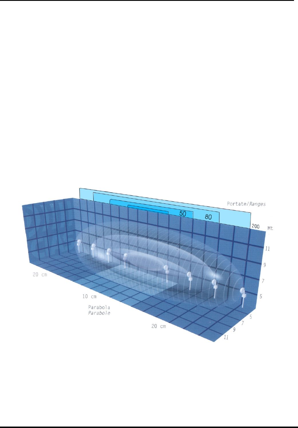
© CIAS Elettronica S.r.l. Ed. 5.0
Installation Handbook page 32 of 59 ERMO 482X PRO
1. DESCRIPTION
1.1 Description
The Ermo 482x PRO equipment is a digital microwave barrier of CIAS, for internal and external
volumetric protection. Such a system can detect the presence of somebody or something moving
within the sensitive field present between a transmitter (Tx) and a receiver (Rx).
The received signal is processed in digital way and analysed with “Fuzzy” logic in order to obtain
maximum performances and a minimum of false alarm rate.
The Ermo 482x PRO equipment is available with the following field range:
- ERMO 482x PRO / 50 Range 50 metri
- ERMO 482x PRO / 80 Range 80 metri
- ERMO 482x PRO / 120 Range 120 metri
- ERMO 482x PRO / 200 Range 200 metri
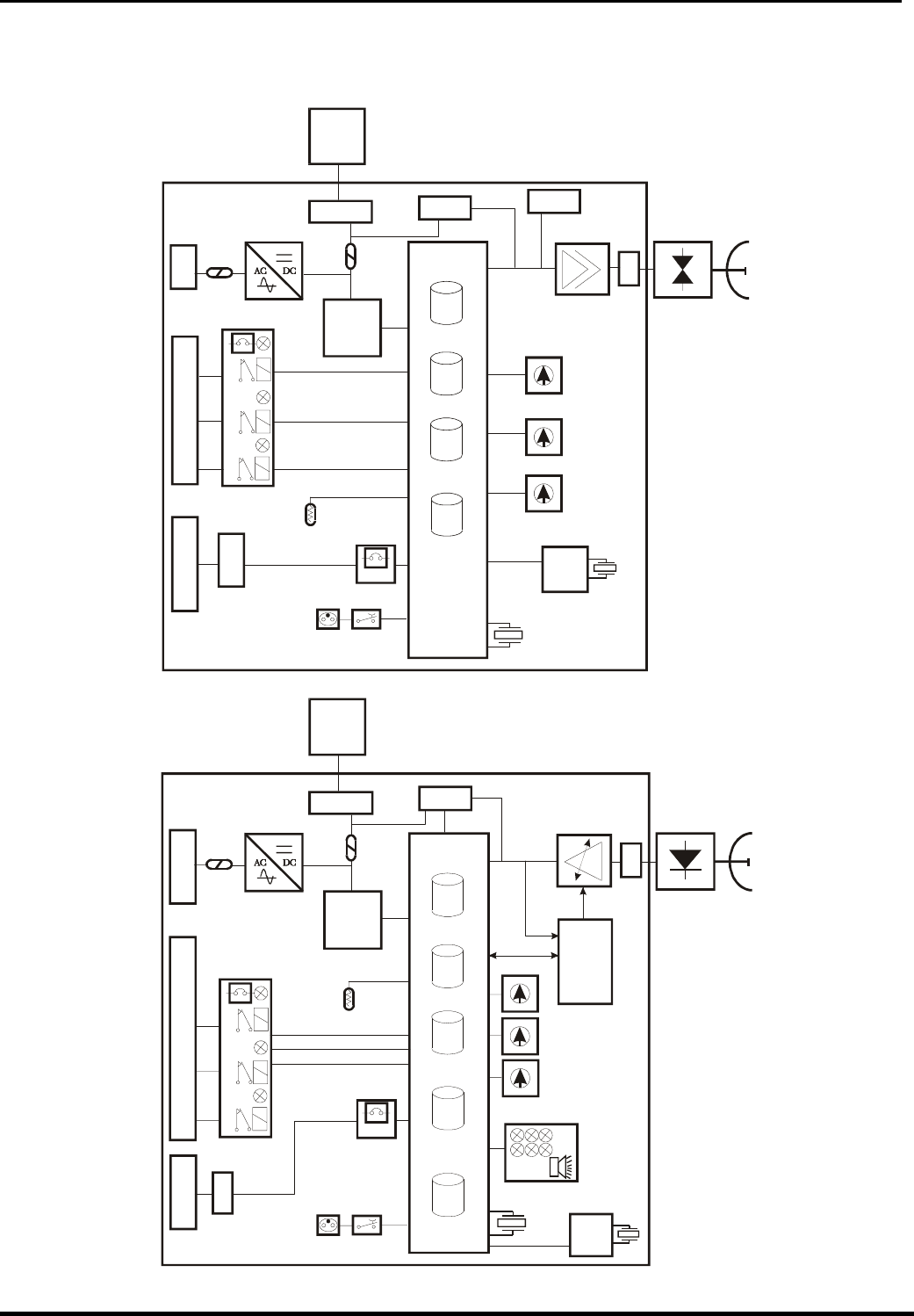
© CIAS Elettronica S.r.l. Ed. 5.0
Installation Handbook page 33 of 59 ERMO 482X PRO
1.2 Block Diagram
In the following diagrams are showed the functional block of the complete Ermo 482X Pro
(Transmitter and Receiver).
Ms4
J1
DEFAULT
PARAMETERS
WORK
PARAMETER S
HYSTORICAL
EVENTS
PASSWORDS
J3
Ms1
F2 F3
MW
OSCILLATOR
10.525 GHz MW
ANTENNA
AMPLIFIER
Jp5
J5
Amp1
CPU
PREAMPLIFIER AND
SYNC SELECTOR
MODULATION
CHANNEL
SELECTOR
RS-485
INTERFACE
RELAYS
ALARM
INTERFACE
POWER SUPPLY AND
BATTERY CHARGER
BATTERY CHARGER
TEMINAL BLOCK
CONNECTOR FOR
MW OSCILLATOR
T°
TEMPERATURE
SENSOR
BOX
OPENING AND TILT
PROTECTIONS
CONNECTOR FOR
SETTING AND
MAINTENANCE
INSTRUMENT
STC-95
0
1
2
3
4
5
6
7
8
9
A
B
C
D
E
F
0
1
2
3
4
5
6
7
8
9
0
1
2
3
4
5
6
7
8
9
NUM. BARRIER
SELECTOR (TEN)
NUM. BARRIER
SELECTOR (UNIT)
RL
FLT
RL
TMP
RL
ALA
SERIAL LINE
CONNECTOR AND
TERMINAL BLOCK
+ 5 Vdc
VOLTAGE
REGULATOR
Sw1
Sw3
Sw2
Ms5
J6
Ms2
Ms3
RTC
Battery
32768 Hz
4.00 MHz
Ermo 482X Pro Transmitter Block Diagram
Ms3
J1
A
NALOG
EVENTS
MONITOR
PASSWORDS
J3
Ms1
F2 F3
MW DETECTOR
10.525 GHz MW
ANTENNA
REGULATED
AMPLIFIER
Jp5
J4
Amp1
Jp4
CPU
RL
FLT
RL
TMP
T°
TEMPERATURE
SENSOR
DIGITAL
A
UTOMATIC
GAIN
CONTROL
RL
ALA
A
LIGNMENT AND WALK TEST
INTERFACE
0
1
2
3
4
5
6
7
8
9
0
1
2
3
4
5
6
7
8
9
FUNCTIONS
SELECTOR
0
1
2
3
4
5
6
7
8
9
SETTING
SWITCHES
Sw1
Sw2
Sw3
Ms2
J5
Ms4
RTC
Battery
CONNECTOR FOR
SETTING AND
MAINTENANCE
INSTRUMENT
STC-95
CONNECTOR FOR
MW DETECTOR
BATTERY CHARGER
TEMINAL BLOCK
POWER SUPPLY AND
BATTERY CHARGER + 5 Vdc
VOLTAGE
REGULATOR DEFAULT
PARAMETERS
WORK
PARAMETERS
HYSTORICAL
EVENTS
32768 Hz
RELAYS
ALARM
INTERFACE RS-485
INTERFACE
BOX
OPENING AND TILT
PROTECTIONS
SERIAL LINE
CONNECTOR AND
TERMINAL BLOCK
11.0592 MHz
Ermo 482X Pro Receiver Block Diagram
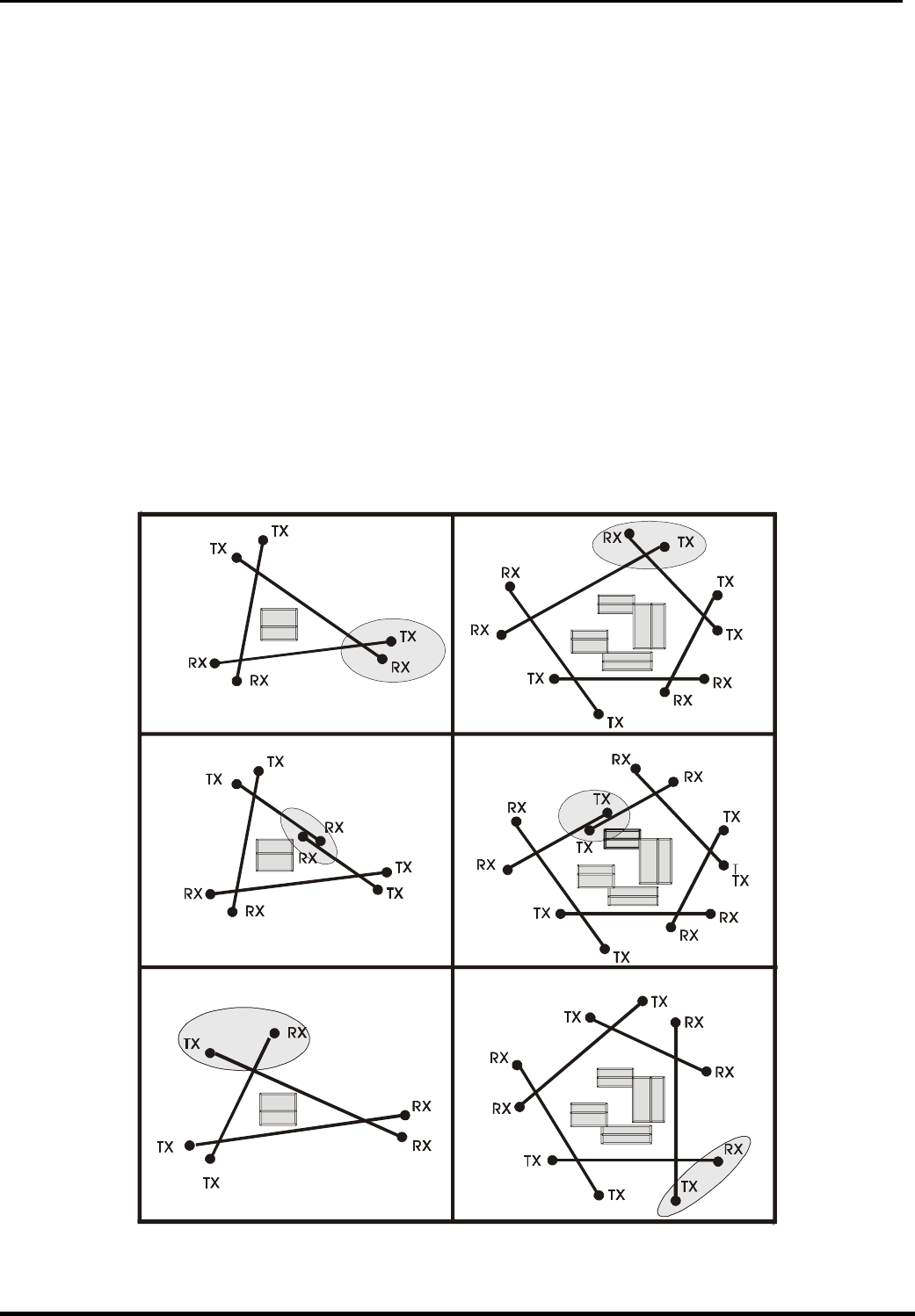
© CIAS Elettronica S.r.l. Ed. 5.0
Installation Handbook page 34 of 59 ERMO 482X PRO
2. INSTALLATION
2.1 Preliminary Information
Due to the various types of ERMO 482x PRO barrier, there are some different kinds of installation
and fixing unit types related to user requirements.
2.2 Number of Sections
Having to design protection with volumetric barriers of a closed perimeter, besides having to split
the perimeter within a certain number of sections that take into account the management need of
the entire plant, it must be remembered that it is always preferable to install an even number of
sections. This consideration is bound to the fact that the likely reciprocal interferences between
adjacent sections are annulled should at the vertices ( cross ) of the polygon, resulting from the
installation of the various sections, be installed two equipment with the same name, two
transmitters or two receivers. It is evident that this might occur only if the number of sections is
even. Should it not be possible to have an even number of sections then some careful
considerations must be made on interferences that might likely occur in order to find the vertex
point where retained best to place the transmitter near the receiver. The following pictures show
some typical cases for which the most correct solution is given ( see figure 1 ).
CORRECT CORRECT
WRONG WRONG
CORRECT CORRECT
Figure 1

© CIAS Elettronica S.r.l. Ed. 5.0
Installation Handbook page 35 of 59 ERMO 482X PRO
2.3 Ground conditions
It is inadvisable to install the equipment along sections with tall grass (more than 10 cm),
ponds, longitudinal waterways, and all those types of grounds whose structure is rapidly
mutable.
2.4 Presence of Obstacles
The fences, are generally metallic therefore highly reflecting hence causing various problems,
for this reasons some precautions are suggested:
- first of all, make sure that the fence has been properly fixed in order that the wind does
not move;
- if it is possible the microwave beam should not be placed in parallel to a metallic fence, is
necessary to create a corner with it;
- metal fences placed behind the equipment night cause distortions to the sensitive beam
especially, and might cause movement detection in unexpected spots, with subsequent
likely generation of false alarms;
- in case of Mw barrier should be installed in a corridor between two metallic fences, the
width of the corridor should be not less to 5 m; if less contact CIAS technical assistance
Along the section, within the area of the protection field, are allowed pipes, poles or similar (e.g.,
lamp posts) as long as their dimensions, with respect to the protection beam, are not too
excessive. The trees, hedges, bushes in general, need very great attention if near or within
the protection beams. These obstacles vary in size and position, in fact they grow and they can
be moved by the wind. Therefore, it is absolutely inadvisable to tolerate the presence of the cited
obstacles within the protection sections.
Figure 2
It is possible to tolerate the presence of these elements near the protection sections only if their
growth is limited through routine maintenance, and if their movement is stopped through
containment barriers. Various Obstacles might be present along the protection sections. For
them there is the need to make the same considerations and take the same necessary
precautions adopted for the above cases. This cause of Dead zones not protected and
Hypersensitive zones which cause false alarm.
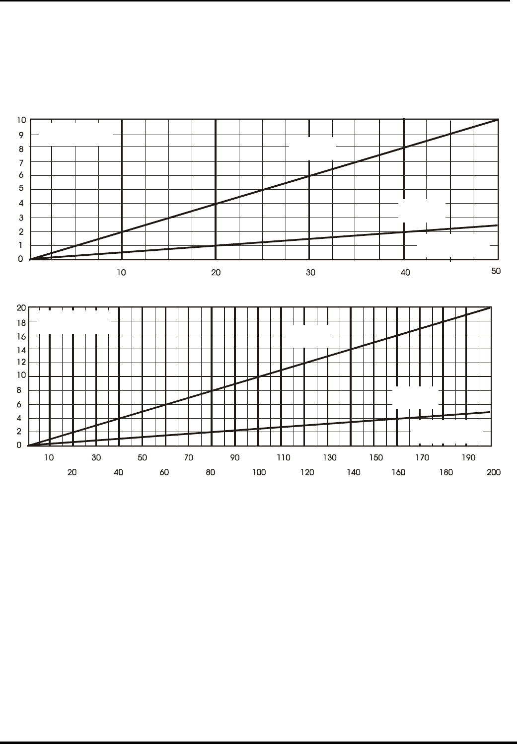
© CIAS Elettronica S.r.l. Ed. 5.0
Installation Handbook page 36 of 59 ERMO 482X PRO
2.5 Amplitude of the Sensitive Beam
The amplitude of the Sensitive Beam depends on the distance between the transmitter and the
receiver, on the antenna type and on the sensitivity adjustment set. The figures below state the
diameter half-way of the sensitive beam section (based on the length of the section) in case of
maximum and minimum sensitivity (see next figures ).
Diameter
Half-Way (m)
Maximum
Sensitivity
Minimum
Sensitivity
Lenght of
the Section (m)
Figure 3 Diameter of sensitive beam at the half-section length (ERMO 482x PRO/ 50)
Diameter
Half-Way (m)
Maximum
Sensitivity
Minimum
Sensitivity
Lenght of
the Section (m)
Figure 4 Diameter of sensitive beam at the half-section length (ERMO 482x PRO/ 80-120-
200)
Remark: that for the ERMO 482x PRO equipment, the sensitivity regulation to be considered to
obtaining the dimensions of the sensitivity beam at half- section length, is that of the
pre-alarm threshold. The higher the pre-alarm threshold the lower the sensitivity,
and vice versa.
It’s important to keep in mind that the pre-alarm threshold determines the beginning of the
intelligent analysis: all signals below this threshold, are considered noise, and anyway of low
importance. All the signals higher this threshold are analyzed following Fuzzy rules.
The prealarm and alarm thresholds, are settable both with software MWATEST and with rotary
switches on board on each receiver. Default setting corresponds to a medium sensitivity fightable
for most of the cases.
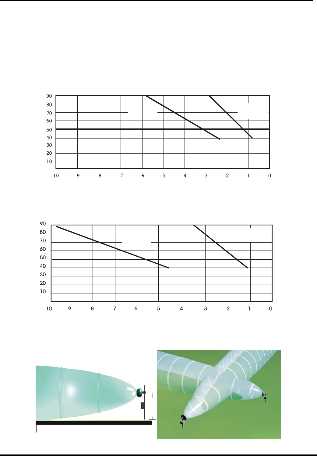
© CIAS Elettronica S.r.l. Ed. 5.0
Installation Handbook page 37 of 59 ERMO 482X PRO
2.6 Length of the Dead Zones near the equipment
The length of the Dead Zones near the equipment is based on the distance of the equipment
from ground, on the sensitivity set on the receiver and on the type of antenna used.
With regard to the considerations stated above, and based on plant requirements, the equipment
must be installed at a certain height from ground. In mean plant the height must be 80 cm.
(from the ground and the centre of the equipment). With medium sensitivity setting, the
suggested crossing overlap is 5 m., for the 80-120-200 m. versions and 3,5 m. for the 50 m.
version.
Minimum
Sensitivity
Length of the
Dead Zone
Installation
Height (cm)
Maximum
Sensitivity
Figure 5 ERMO 482x PRO-50: Dead zone length near the equipment versus installation height.
Installation
Height (cm)
Minimum
Sensitivity
Maximum
Sensitivity
Length of the
Dead Zone (m)
Figure 6 ERMOx 482. 80-120-200: Dead zone length near the equipment versus
installation height.
5 M
80-85 cm
Dead Zone
Dead Zone
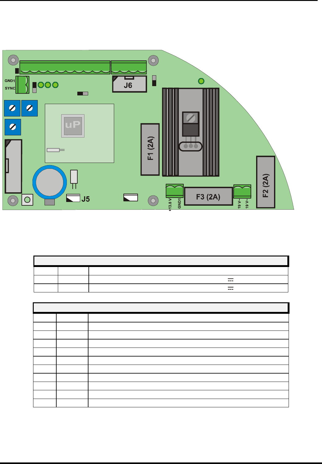
© CIAS Elettronica S.r.l. Ed. 5.0
Installation Handbook page 38 of 59 ERMO 482X PRO
3.1 Terminal Blocks, Connectors and Circuits Functions
3.1.1 Transmitter Circuit
AMP1
J3
MS1 MS2
S1
SW2
SW3
SW1
Jp5
Rete
Jp6
J1
Jp1
OUTSYNCIN
MS 4
MS
5
21 12
11
223
3445678910
ING
GND
TEST
ST.BY
GTS2
GTS1
PT 2
PT 1
ALL2
ALL1
L0
LH
GND1
13,8V
Jp4
1
2
MS 3
D7D8 D9 D15
1
1
Batteria
BackUp
Figure 8 Layout of connectors, jumpers, LEDs and presetting in transmitter board
The following tables shows the connector pin functions present on ERMO 482x PRO Transmitter
TRANSMITTER TERMINAL BLOCK MS2
Term Symbol Function
1 19 V~ Mains ac power supply input (19 V~) or (24V )
2 19 V~ Mains ac power supply input (19 V~) or (24V )
TRANSMITTER TERMINAL BLOCK MS4
Term Symbol Function
1 ALL 1 Alarm relay contact (Normally Closed)
2 ALL 2 Alarm relay contact (Normally Closed)
3 PT 1 Tamper relay contact (Normally Closed) + bulb contact (AMP1)
4 PT 2 Tamper relay contact (Normally Closed) + bulb contact (AMP1)
5 GST 1 Fault relay contact (Normally Closed)
6 GST 2 Fault relay contact (Normally Closed)
7 ST BY Auxiliary input for Stand-By command (Norm. Open from GND)
8 TEST Auxiliary input for Test command (Norm. Open from GND)
9 GND Ground auxiliary connection
10 ING Balanced Line Input for external device (detector)
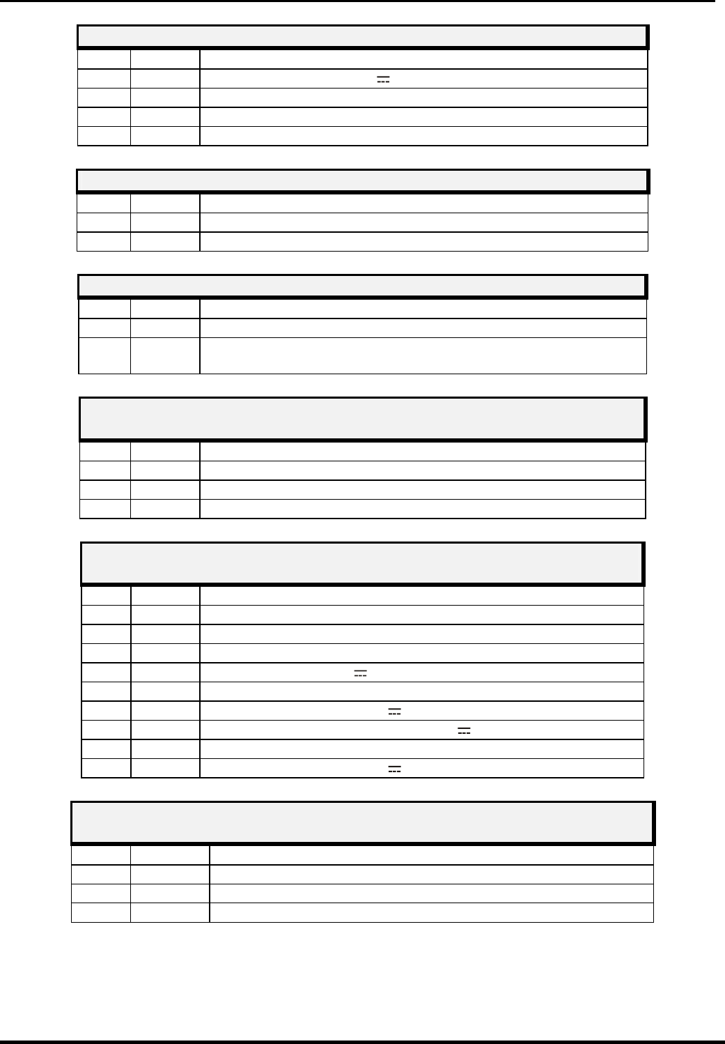
© CIAS Elettronica S.r.l. Ed. 5.0
Installation Handbook page 39 of 59 ERMO 482X PRO
TRANSMITTER TERMINAL BLOCK MS5
Term Symbol Function
1 +13,8 Dc Power Supply (13,8 V ) for RS-485/232 converter
2 GND 1 Ground connection for Data and Power Supply
3 LH + RS 485 (High Line)
4 LO - RS 485 (Low Line)
TRANSMITTER TERMINAL BLOCK MS1
Term Symbol Function
1 13,8V +13,8 VDC Connection for Battery (Protection Fuse F3 = T2A)
2 GND 1 Ground connection for Battery
TRANSMITTER TERMINAL BLOCK MS3
Term Symbol Function
1 GND 1 Ground connection for sync cable
2 SYNC Sync In/Out connection to perform Slave/Master operation
setting JP1
TRANSMITTER CONNECTOR J1
Connector for MW oscillator (DRO)
Term Symbol Function
1 GND Ground connection for MW oscillator
2 DRO Modulation Frequency connection for MW oscillator
3 GND Ground connection for MW oscillator
TRANSMITTER CONNECTOR J3
Measure Connector
Term Symbol Function
1/3 N.C. Not Connected
4 GND Ground
5 N.C. Not Connected
6 +13,8 Power Supply (13,8 V )
7/11 N.C. Not Connected
12 +5V Internal Power Supply (5 V )
13 OSC Oscillator functioning Measure (+ 4V = OK)
14/15 N.C. Not Connected
16 +8V Internal Power Supply (8 V )
TRANSMITTER CONNECTOR J5
Micro switch Connector for Radome Tamper
Term Symbol Function
1 GND Ground connection for Tamper
2 ING Tamper Input
3 GND Ground connection for Tamper
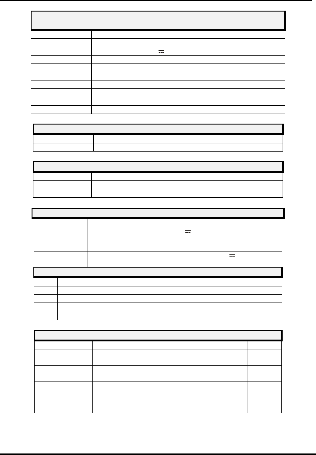
© CIAS Elettronica S.r.l. Ed. 5.0
Installation Handbook page 40 of 59 ERMO 482X PRO
TRANSMITTER CONNECTOR J6
10 pin Connector for direct PC Serial Line connection (Mwatest SW)
Term Symbol Function
1/2 N.C. Not Connected
3 +13,8 Power Supply (13,8 V ) Converter interface RS-485/232
4 N.C. Not Connected
5 LO Low Line for RS 485
6 N.C Not Connected
7 LH High Line for RS 485
8 N.C. Not Connected
9 GND Ground
10 N.C. Not Connected
TRANSMITTER CHANNELS SWITCH
N° Symbol Function
1 SW1 Hexadecimal Modulation Channel Selector
TRANSMITTER NUMBER OF BARRIER SWITCHES SW2 SW3
N° Symbol Function
2 SW2 Barrier Number selector (units column)
3 SW3 Barrier Number selector (tens column)
TRANSMITTER FUSES
N° Symbol Function
1 F1 Tx Circuit Power supply (13,8 V ) protection fuse (T2A-250V
slow blow)
2 F2 AC Power supply protection fuse 19 V~ (T2A-250V slow blow)
3 F3 Power supply protection fuse for Battery 13,8 V (T2A-250V
slow blow)
TRANSMITTER LEDS
N° Symbol Function Default
7 D7 Fault indication. ( OFF by means of Jp4) ON
8 D8 Tamper indication. ( OFF by means of Jp4) ON
9 D9 Alarm indication. ( OFF by means of Jp4) ON
15 D15 Main presence indication ON
TRANSMITTER JUMPERS
N° Symbol Function Default
1 Jp1 Internal Modulation signal (Tx-Master, Sync-Out)
or External Modulation signal (Tx Slave, Sync-In) OUT
4 Jp4 Exclusion for fault, tamper and alarm indication
Leds (Jp4 DOWN leds OFF) ON
5 Jp5 RS485 Line termination (Jp5 DOWN line
terminated) OFF
6 Jp6 Enable / Disable Balanced Line Input (Closed =
Input disabled) OFF

© CIAS Elettronica S.r.l. Ed. 5.0
Installation Handbook page 41 of 59 ERMO 482X PRO
3.1.2 Receiver Circuit
AMP1
MS1 MS2
J3
J4
JP5
SW3 SW2
SW1
S3
D 17
S 1
J1
11
223
3445678910
ING
GND
TEST
ST.BY
GTS2
GTS1
PT 2
PT 1
ALL2
ALL1
L0
LH
GND1
13,8V
GND1
12
+13,8 V
12
19V~
19V~
D7D9 D6 D8
D10D11
MS3 MS4
1
1
Jp4
Batteria
BackUp
1
Jp3
Figure 9 Layout of connectors, jumpers, LED and presetting in receiver board
The following tables shows the connector pin functions present on ERMO 482x PRO Receiver
board.
RECEIVER TERMINAL BLOCK MS2
Tem Symbol Function
1 Vac Mains ac power supply input (19 V~) or (24V )
2 Vac Mains ac power supply input (19 V~) or (24V )
RECEIVER TERMINAL BLOCK MS3
Term Symbol Function
1 ALL 1 Alarm relay contact (Normally Closed)
2 ALL 2 Alarm relay contact (Normally Closed)
3 PT 1 Tamper relay contact (Normally Closed) + bulb contact
4 PT 2 Tamper relay contact (Normally Closed) + bulb contact
5 GST 1 Fault relay contact (Normally Closed)
6 GST 2 Fault relay contact (Normally Closed)
7 ST BY Auxiliary input for Stand-By command (Norm. Open from GND)
8 TEST Auxiliary input for Test command (Norm. Open from GND)
9 GND Ground auxiliary connection
10 ING Balanced Line Input for external device (detector)
RECEIVER TERMINAL BLOCK MS1
Term Symbol Function
1 +13,8 + 13,8 VDC Connection for Battery (Protection Fuse F3 =T2A)
2 GND 1 Ground connection for Battery

© CIAS Elettronica S.r.l. Ed. 5.0
Installation Handbook page 42 of 59 ERMO 482X PRO
RECEIVER TERMINAL BLOCK MS4
Term Symbol Function
1 +13,8 Dc Power Supply (13,8 V ) for RS-485/232 converter
2 GND 1 Ground connection for Data and Power Supply
3 LH + RS 485 (High Line)
4 LO - RS 485 (Low Line)
RECEIVER CONNECTOR J1
Connector for MW detector
Term Symbol Function
1 GND Ground connection for MW oscillator
2 DET Connection for MW detector
3 GND Ground connection for MW oscillator
RECEIVER CONNECTOR J3
Measure Connector
Term Symbol Function
1/3 N.C. Not Connected
4 GND Ground
5 N.C Not Connected
6 +13,8 Power Supply (13,8 V )
7/8 N.C Not Connected
9 0,2V. Detected Signal 200 mVpp
10/11 N.C. Not Connected
12 +5V Internal Power Supply (5 V )
13 N.C Not Connected
14 VRAG Automatic Gain Control Voltage
15/16 N.C. Not Connected
RECEIVER CONNECTOR J4
Micro switch Connector for Radome Tamper
Term Symbol Function
1 GND Ground connection for Tamper
2 ING Tamper input
3 GND Ground connection for Tamper
RECEIVER CONNECTOR J5
10 pin Connector for direct PC Serial Line connection (Mwatest SW)
Term Symbol Function
1/2 N.C. Not Connected
3 +13,8 Power Supply (13,8 V ) converter interface RS-485/232
4 N.C. Not Connected
5 LO Low Line for RS 485
6 N.C Not Connected
7 LH High Line for RS 485
8 N.C. Not Connected
9 GND Ground
10 N.C. Not Connected

© CIAS Elettronica S.r.l. Ed. 5.0
Installation Handbook page 43 of 59 ERMO 482X PRO
RECEIVER FUSES
N° Symbol Function
1 F1 Power supply (13,8 V ) protection fuse (T2A-250V slow blow)
2 F2 AC Power supply protection fuse 19 V~ (T2A-250V slow blow)
3 F3 Power supply protection fuse for Battery 13,8 V (T2A-250V slow
blow)
RECEIVER JUMPERS
N° Symbol Function Default
3 Jp3 Data and Parameters Battery Back-Up OFF (Jp3 right
position = battery connected (ON) ON
4 Jp4 Leds OFF from D6 to D11 (Jp4 UP = Leds OFF) ON
5 Jp5 RS 485 Line termination (Jp5 DOWN line terminated) OFF
RECEIVER LEDS
N° Symbol Function Default
6 D6 Fault indication + Alignment and setting functions ON
7 D7 Tamper indication + Alignment and setting functions ON
8 D8 Alarm indication + Alignment and setting functions ON
9 D9 Alignment and setting functions OFF
10 D10 Alignment and setting functions OFF
11 D11 Alignment and setting functions OFF
17 D17 Main presence indication ON
SET –UP BUTTON FOR ALIGNEMENT AND SETTING
N° Symbol Function
1 S3 Button to accept data in alignment operation and to write
parameter in setting operations
RECEIVER FUNCTION SWITCH SW1
N° Symbol Function
1 SW1 10 positions functions rotary switch:
Position 1 = Barrier alignment
Position 2 = acquisition, of the installation values (Channel number
and AGC Voltage)
Position 3 = Prealarm thresholds Read/Write
Position 4 = Alarm thresholds Read/Write + Walk-Test
Position 5 = Masking thresholds Read/Write
Position 6 = Upper Prealarm thresholds Read/Write (FSTD)
Position 7 = Lower Prealarm thresholds Read/Write (FSTD)
Position 8 = Barrier number Read/Write
Position 9 = Alignment procedures ending (balanced line Active)
Position 0 = Alignment procedures ending (balanced line Inactive)
PARAMETERS AND BARRIER NUMBER READING AND SETTING
SWITCHES SW2- SW3
N° Symbol Function
2 SW2 Decimal rotary switch to read or to set parameters during the
alignment operations (units column)
2 SW3 Decimal rotary switch to read or to set parameters during the
alignment operations (tens column)

© CIAS Elettronica S.r.l. Ed. 5.0
Installation Handbook page 44 of 59 ERMO 482X PRO
3.2 Equipment Connection to the Power Supply
Even if the equipment is Direct Current powered ( 13,8 V ), they still operate properly, but it is
advisable to power it by Alternating Current ( 19 V~ ) or (24 V ).
3.2.1 Connection to the Power Supply
The connection between the equipment and the transformer must be as short as possible (less
then 4 meters), and the section of the conductor must not be less than 1.5 mm².. The connection
between the transformer and the 115 V~ mains will be as that of the previous one.The power
supply cables connecting transformer with equipment, must be of shielded type with shield
connected to ground. The connection between unit and the power supply must be realised with
cables of correct section, the cables section must be computed keeping in account connection
length and unit current absorption. For the power supply connection (Alternating Current ) 19V~,
to make connect term 1/2 on the terminal strep MS2 of the Rx and Tx circuit. The protection fuse
is F2 is 2 A (T2A) slow-blow type.
Use only safety transformers with the following characteristics:
• primary voltage: 115 V~
• secondary voltage 19 V~
• minimum power 30 VA
Remark: use only safety transformers (example Certified EN 60950)
Make sure to connect the body of the transformer to hearth tap.
The transformer connection to the main (115 V~), must be carried out through
one circuit breaker having the following characteristics:
• bipolar with minimum distance between contacts equal to 3 mm
• provided in the fix part of cabling
• easily accessible
However laws and standards concerning installations of devices permanently connected
to the main (115 V~), must be strictly respected (in Italy Law 46/90 and standard CEI 64-8).
Remark: if the barrier power supply is an external dc voltage (13,8V ), to avoid the activation
of the fault contact, due to main missing for more than 3 hours, it’s necessary to
connect the positive incoming voltage (13,8V ), also to the terminal 1 or 2 of the
terminal block MS2 either on transmitter and receiver PCB
3.2.2 Connection of stand-by Battery
Into each equipment heads there is the housing for an optional rechargeable back-up lead
Battery 12 V – 1.9 Ah (optional). The battery is charged by the internal power supply, through
the red and black fastons and wires connected to the terminals 1 and 2 of the terminal block MS1
of the Rx and Tx circuit. The provided protection fuse (against overload and/or battery polarity
inversion) F1 is 2A (T2A) slow-blow type The back-up lead battery allows to the barrier head (TX
or RX), at least 12 hours of perfect working, in case of mains missing.
Remark: package, of the optional standby battery, must have a flame class equal or better than
HB ( UL 94 Standard ).

© CIAS Elettronica S.r.l. Ed. 5.0
Installation Handbook page 45 of 59 ERMO 482X PRO
3.3 Connection to the Control Panel
3.3.1 Alarm contacts: Alarm, Tamper, Fault
On transmitter and receiver PCB are present 3 relays. These Relays are static with dry contacts
normally closed. By means of these contacts it’s possible to communicate to the control panel the
following conditions:
• ALARM, TAMPER, FAULT
There are also 3 inputs to activate the following functions:
• Test (TX and RX)
• Stand-by (TX and RX)
• Synchronism (only TX)
The output contacts for alarm, tamper and fault, both on transmitter and receiver, are made by
Static Relays with maximum current of 100 mA.
Remark: in closed condition the resistance of these contact is about 40 ohm.
The connections to control panel must be made by means of shielded cables.
The relays are activated for the following reasons:
- ALARM RELAYS
1- Pre-alarm on receiver ( Remark1 )
2- Intrusion alarm on receiver
3- Receiver masking condition alarm
4- Alarm of external detector connected at Auxiliary Balanced Line
5- Successful result of test procedure operation on receiver
6- Insufficient received signal (V RAG >6,99V)
7- Channel alarm.
- TAMPER RELAYS
1- Cover removing (radome) (TX and RX)
2- Tilt Bulb position (TX and RX)
3- Tampering of external detector connected at Auxiliary Balanced Line
4- Cut of Auxiliary Balanced Line
5- Short circuit of Auxiliary Balanced Line.
- FAULT RELAYS
1- Battery voltage low (< +11V )
2- Battery voltage high (> +14.8V )
3- Temperature low (< -35°C internal)
4- Temperature high (> +75°C internal)
5- Fault of external detector connected at Auxiliary Balanced Line
6- RF (radio frequency) or BF (low frequency) Oscillator fault on Transmitter
7- Mains missing or power supply fault (more then 3 hours)
Remark 1: if the intrusion signal, after overcoming the pre-alarm threshold, stays for 40 sec
between pre-alarm and alarm threshold, the barrier gives a “pre-alarm” event, and
the alarm output is activate (the contact become opened).

© CIAS Elettronica S.r.l. Ed. 5.0
Installation Handbook page 46 of 59 ERMO 482X PRO
3.3.2 Synchronism connection
For the Synchronism operation between two Transmitters, it is necessary to interconnect the
terminals 2 “SYNC” and 1 “GND1” of terminal block MS3 of both Transmitters.
It is also necessary to select one Transmitter as “Master” and the other as “Slave”, by means of
jumper Jp1.
• Jp1 = “IN” position, the terminal 1 of MS3 is the input for an external synchronism signal,
so the Transmitter is “Slave”.
• Jp1 = “OUT” position, the terminal 1 of MS3 is the output for the synchronism signal
internally produced, so the Transmitter is “Master”
Remark: the cable connecting the two transmitters, must be as short as possible and not more
than 10 meters. If cables longer than 10 meters are required, it is necessary to use the
synchronism repetition circuit mod. SYNC 01.
3.3.3 Stand-by connection
For the Stand-by function activation, it is necessary connect to ground the terminal 7 “STBY” of
MS3 terminal block for the receiver circuit and connect to ground the terminal 7 “STBY” of MS4
terminal block for the transmitter circuit.
Remark: the Stand-by operation, doesn’t inhibit the barrier functionality, but deactivate the record
of events into “historical file” (TX and RX) and in the monitor file (RX).
3.3.4 Test connection
The Test function will be activated connecting to ground the terminal 8 “TEST” of the terminal
block MS4 on Transmitter circuit. If the test procedure is successful done, the alarm relays on
Receiver circuit will be activated later 10 second.
Remark: for high risk protection it’s necessary a Periodic Test for the equipments. By means for
these control panel will be able to detect tamper action. For the Test function activation
it witch have Ermo-Test instrument; it’s possible to test the microwave barrier,
temporary switching-off the transmitter.
3.3.5 Balanced Line connection
Either on transmitter and receiver PCB is provided a Balanced input were it’s possible to connect
an external detector and manage its activity trough each head (TX or RX). To activate this
function on the TX PCB, it’s necessary to open Jp5 jumper. To activate this function on the RX
PCB, it’s necessary to end the alignment procedure, leaving the function selector SW1 in position
9 instead of 0. The balanced inputs are provided at terminals 10 (ING) and 9 (GND) on terminal
block MS4 of the transmitter PCB, and MS3 of the receiver PCB. By these inputs it’s possible to
manage the following conditions of external detectors:
• rest condition of external detector
• alarm condition of external detector
• tamper condition of external detector
• fault condition of external detector
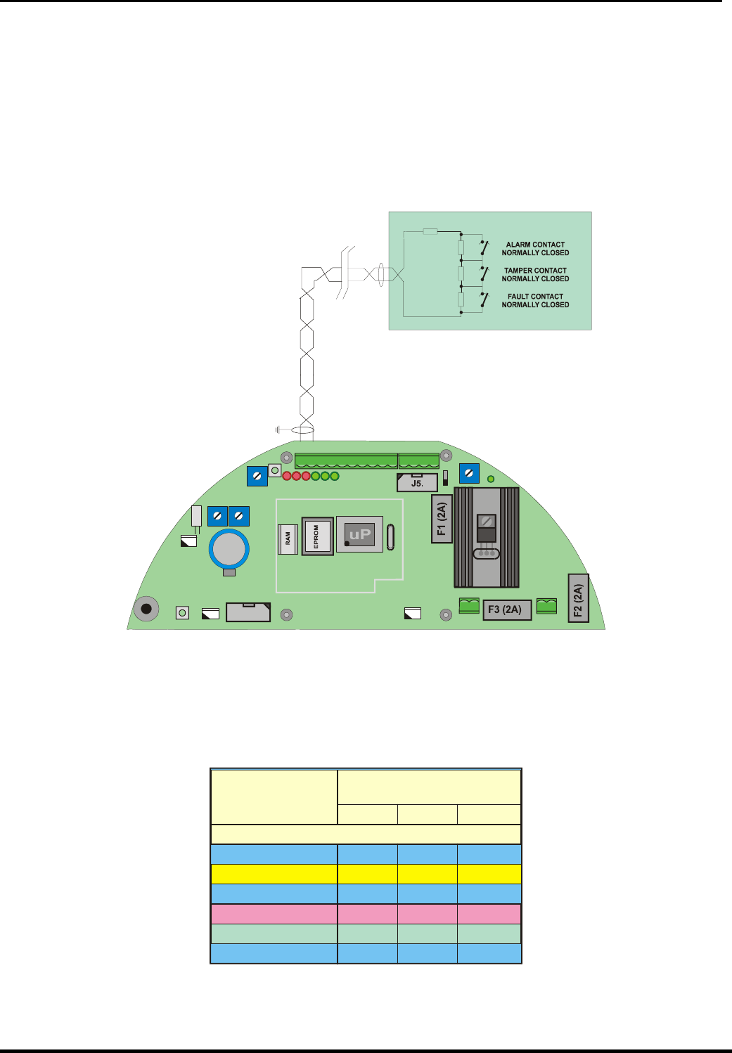
© CIAS Elettronica S.r.l. Ed. 5.0
Installation Handbook page 47 of 59 ERMO 482X PRO
In addition it’s possible to manage the following conditions:
• Line cut condition of the wires connecting the external detector at TX or RX PCB
• Short Circuit condition of the wires connecting the external detector at TX or RX PCB
To manage all these conditions it’s necessary to use weighting resistors connected like that
showed in the following picture.
RECEIVER PCB
AMP1
MS1 MS2
J2
J3
J4
JP5
SW3 SW2
SW1
S3
D 17
S 1
J1
11
223
3445678910
ING
GND
TEST
ST.BY
GTS2
GTS1
PT 2
PT 1
ALL2
ALL1
L0
LH
GND1
13,8V
GND1
12
+13,8 V
12
19V~
19V~
D7D9 D6 D8
D10D11
MS3 MS4
470
Ω
470
Ω
1K
1,5K
Ω
Ω
EXTERNAL DETECTOR
In the following table are indicated the voltage values present at balanced inputs for the possible,
detector and line, conditions. It is possible to read this values, also by means of MWA TEST SW
in the “Analogue values” window. (PC in local or remote connection)
0- 0.5
LINE SHORT CIRCUIT
CONDITIONS INPUT VOLTAGE
[V dc]
LINE CUT
FAULT
TAMPER
ALARM
REST
0.5 1 1.5
1.5 2 2.5
2.5 3 3.5
3.5 4 4.5
4.5 - 5
Min. Average Max.

© CIAS Elettronica S.r.l. Ed. 5.0
Installation Handbook page 48 of 59 ERMO 482X PRO
3.4 Serial Line RS-485
3.4.1 RS - 485 / 232 Network Connection Interface
A standard RS 485 serial interface is provided on both transmitter and receiver of the ERMO 482
X barrier. The communication parameters are the following:
Mode: Asynchronous - Half-Duplex
Baud rate: 9600 b/s
Character length: 8bit
Parity control: No Parity
Stop bit: 1
3.4.2 RS -485 Serial Line connections
The way of laying down the cable must be “multidrop” type (BUS), and the derivations for units
connection as short as possible. It is possible to use others cabling configurations like:full Star
type, mixed, Star and BUS type. Connect to the terminal 4 “LO” (“RS 485 –“ negative data line );
to the terminal 3 “LH” (“RS 485+” positive data line ) and to the terminal 2 “GND1” (data ground
line) of the terminal block MS4 for the Receiver PCB and MS5 for the Transmitter PCB. To
connect a PC on serial line is necessary to use a serial line converter RS 485/232 included in
MWA TEST sw.
Cable for connection of all the heads Rx and Tx
To the maintenance P. C. with MWA TEST Software
Connector
interface
MS4(Tx),
MS5(Rx
Connector
25 pin
N° N° Symbol Function
1 12
+13,8 Power supply (13,8 VDC) per for 485/232 converter
2 9
GND Ground data and power supply for 485/232 converter
3 10
LH 485 High Line for RS 485
4 11
LO 485 Low Line for RS 485
3.4.3 Network Configuration and Signal Repeaters
The interconnection cable concerning barrier management through a remote P.C. must be
suitable for a RS485 serial data line, i.e., it must be a low capacity cable with 3 twisted and
shielded leads (70 pF/mt.) for example “Belden 9842”.The limit distances of the RS 485
connection is 1200 meters. For longer distances use one or more interface Regenerators (BUS
REP), see figure 11. The way of laying down the cable must be of BUS type, and the derivations
for units connection as short as possible. It is possible to lay down the cable in different manner:
full stellar; mixed, stellar and BUS type, using Repeaters / Regenerators and interface multipliers
(BUS REP), see figure 11. The total number of units (Tx and Rx) that can be connected to the
line are 32, for an higher number of units, it is necessary the use of one or more line regenerator
RS 485, this is true also in case of cable length lower than 1200 metres. Screen connection
continuity must be guaranteed to properly protect the cited line from induced noise. To this
concern the screen will have to be GROUNDED only in one point, i.e., near the power supply
unit. The power supply voltage to the RS485 / RS 232 interface converter must be delivered by a
local power supply unit, which will have to be placed near the converter proper For the central
COM-BS connection, the serial line coming from the barriers can be used directly without any
conversion.
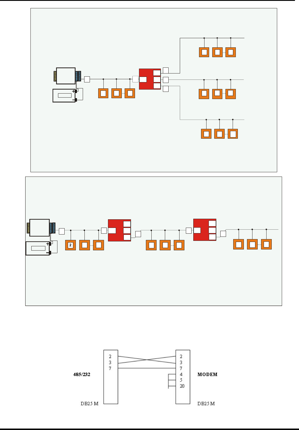
© CIAS Elettronica S.r.l. Ed. 5.0
Installation Handbook page 49 of 59 ERMO 482X PRO
The figure shows a system which requires a RS 485 serial line with several branch loops(“Star”
network architecture) This architecture is created using a BUSREP as a multiplier.The 4 resulting
sections can be up to 1,200 mt. long each and a maximum of 32 devices,including the BUSREP,
can be connected to each one. The first section includes the seriale line converter
“STAR” NETWORK ARCHITECTURE USING “BUSREP” AS A MULTIPLIER
Line RS- 485
max 1200 mt. L1
L4
BUSREP 1
L3
L2
Field
Devices
32
2
13,8 Vcc
0 Vcc
LOCAL
POWER-SUPPLY
SERIAL LINE
CONVERTER
RS-485/RS-232
RS-485
RS232
13
11
1
1
1
1
331
Field
Devices
Line RS- 485
max 1200 mt.
2332
Line RS- 485
max 1200 mt.
Field
Devices
2332
Field
Devices
2332
1
The figure shows a system which requires a RS 485 serial line that is longer than 1,200 metres.
Using two BUSREPs as regenerators, it was divided up into 3 sections each of which was shorter in length.
In this case there are less than 32 field devices, but they can be distributed on 3,600 metres-long line.
Field
Devices Field
Devices
Field
Devices
L1
L4
BUSREP 1
L3
L2
L1
L4
BUSREP 2
L3
L2
310
11
13
12
14 20
21
23
22
24 29
13,8 Vcc
0 Vcc
LOCAL
POWER-SUPPLY
SERIAL LINE
CONVERTER
RS-485/RS-232
RS-485
RS232
13
11
1
1
3.5 Remote Connection
To interface ERMO 482x PRO barrier to PSTN modem (9600 b/s) it is necessary the conversion
RS485 to RS232 and also the cross conversion shown below.

© CIAS Elettronica S.r.l. Ed. 5.0
Installation Handbook page 50 of 59 ERMO 482X PRO
4. ADJUSTMENT AND TESTING
4.1 Adjustment and Testing
A built in electronic alignment, parameter set and test tool, is provided in the receiver head of the
ERMO 482X PRO barrier. This is a very useful system both for installation and periodical
maintenance.
4.1.1 Transmitter Setting-up
To remove the radome unscrew the 6 screws until they turn loose, then release them out gently
without remove them completely. Rotate the radome anticlockwise (about 20°) and release it. To
close the MW head, fit the radome to it keeping the central logo rotated 20° anticlockwise. Rotate
the radome clockwise till the central logo is correctly positioned and then tight the 6 screws.
• Check the a.c. power voltage (19 V~) or d.c. (24 V ) at terminals 1 and 2 on terminal block
MS2 (Fig. 7).
• Disconnect the battery and check on the “fastons” the d.c. power supply voltage presence
(13.8V ).
• Reconnect the “fastons” to the battery paying attention to the polarity:
red wire (terminal 1 of MS2) to battery positive terminal
black wire (terminal 2 of MS2) to battery negative terminal.
Remark: any battery polarity reversal, blows the relative fuse (F2). The equipment will operate
properly after having correctly inserted the “fastons” and after having replaced the
blown fuse (T2A).
• Select, one of the 16 modulation channel available, by the hexadecimal switch (within 0 and
F). To increase the resistance to tampering actions, it is a good rule to preset different
channels for the different barriers installed in the same site. The use of different channel
doesn’t affect the detection ability of the barrier.
Remark: if one RX receives MW signal from its own transmitter and from another interfering
transmitter (for example due to reflections or any other field reason), it is necessary to
synchronize the two transmitters, selecting one as Master and the other as Slave. In
this case the modulation channel, for the slave transmitter, is the same selected on the
Master regardless its own selection.
It is possible to address each Transmitter Head thanks to the selectors SW2 and SW3.
How to write the address in the TX head: it is enough to select a number between 01 and 99
(00 means barrier 100), by the two rotary switches SW2 (units column) and SW3 (tens
column).
• Close the radome. To do this operation place the Radome near the back cover, keeping the
central logo rotated anticlockwise of 20°. Before to close the head ensure that the tilt switch is
vertically positioned. Then fit the front cover to the back cover and rotate it clockwise until the
central logo will be correctly positioned and tighten the screws.

© CIAS Elettronica S.r.l. Ed. 5.0
Installation Handbook page 51 of 59 ERMO 482X PRO
4.1.2 Receiver Setting-up
• To remove the radome unscrew the 6 screws until they turn loose, then release them out
gently without remove them completely. Rotate the radome anticlockwise (about 20°) and
release it. To close the MW head, fit the radome to it keeping the central logo rotated 20°
anticlockwise. Rotate the radome clockwise till the central logo is correctly positioned and then
tight the 6 screws.
• Check the a.c. power voltage (19 V~) or d.c. (24 V ) at terminals 1 and 2 on terminal block
MS2 (Fig. 8).
• Disconnect the battery and check on the “fastons” the d.c. power supply voltage presence
(13.8Vdc).
• Reconnect the “fastons” to the battery paying attention to the polarity:
red wire (terminal 1 of MS2) to battery positive terminal
black wire (terminal 2 of MS2) to battery negative terminal.
Remark: any battery polarity reversal, blows the relative fuse (F2). The equipment will operate
properly after having correctly inserted the “fastons” and after having replaced the
blown fuse (T2A).
• To make the barrier alignment and parameters setting of the barrier using the built in tool,
make a preliminary visual mechanical alignment see the following instructions:
a. Be sure that the tamper switch is activated (Open circuit)
b. Select by the “function switch” SW1 position 1. The electronic alignment phase is activated.
c. Push S3 button. This action adjust the signal level and freeze, after some seconds, the
Automatic Gain Control. In that condition red leds D9, D10, D11 will be ON and green leds D6,
D 7, D8 will be OFF, and the buzzer BZ1 will produce a pulsed sound, this means that the
field signal has reached the proper working level.
d. Unscrew lightly the bracket screws and move the horizontal alignment of the receiver, looking
for the maximum received signal.
e. If, during the alignment, one or more green leds become ON means that the received signal
level is increased compared with the previous. In this case also the pulse frequency of the
sound produced by the on board buzzer, increase. Push again the button S3 and when the
green leds become OFF (proper working level), move horizontally in the same direction.
If during the movement for the alignment, instead of become ON the green leds, become OFF
one o more red leds, and the pulse frequency of the sound produced by the buzzer, decrease,
means that the received signal level is decreased compared with the previous, so it is
necessary to move back in the other horizontal direction and look for a better received signal.
If there is not a new maximum level, means that the present horizontal alignment is the best.
f. Unscrew lightly the bracket screws of the transmitter and move the horizontal alignment,
looking for the maximum received signal on the receiver head like indicated in the previous
point “e”.
g. Once the best alignment is reached (maximum signal available), screw strongly the bracket
screws, both on transmitter and receiver, to block the horizontal movement.
h. Unblock the vertical movement of the receiver and move it slightly upward. Push S3 button
and then move the head downward looking for the maximum signal like indicated in the
previous point “e”.

© CIAS Elettronica S.r.l. Ed. 5.0
Installation Handbook page 52 of 59 ERMO 482X PRO
i. Unblock the vertical movement of the transmitter and repeat the operation described for the
receiver vertical alignment. Once the best vertical alignment is reached (maximum signal
available), block the vertical movement both on transmitter and receiver.
j. Select by the “function switch” SW1 position 2. The acquisition, of the installation values,
phase is activated. The installation values are the AGC voltage (V RAG) and the modulation
channel number. To complete the phase it is necessary to be sure that nothing change the
MW field state (for example the installer himself), then push the button S3 and wait few
seconds. When only the three green leds become ON, the phase is successfully completed. If
also the three red leds become ON means that the barrier will works but the signal received
was bed (too much noise or something interfering in the MW field). Push again the button S3
been sure that nothing interferes. If only the three red leds become ON the phase is
completely aborted, it is necessary to repeat the alignment phase, starting from the previous
point “e”, being sure that no obstacles are present in the MW field.
k. Select by the “function switch” SW1 position 3. The prealarm thresholds adjusting phase is
activated. The two prealarm thresholds are set under and over the rest field value. The
analysis process begin when the field value, overcomes one of them. If the field value remain
between the prealarm and the alarm threshold continuously for about 40 seconds, a prealarm
event is generated and the alarm relay is activated.
To read the present prealarm threshold value operate as follow:
• Rotate decimal switch SW3 (tens column) until the first red led (D9) becomes ON .
• Rotate decimal switch SW2 (units column) until the second red led (D10) becomes ON .
The reading values will be included between 01 and 80 (default value 15) Decreasing the
threshold value the sensitivity increase like the beam dimension.
To modify the present value increasing the sensitivity it is necessary to set, by means of the
two switches SW3 and SW2 a lower value and then push the button S3. To decrease the
sensitivity, it is necessary to set by means of the two switches SW3 and SW2, a higher value
and then push the button S3.
l. Select by the “function switch” SW1 position 4. The alarm thresholds adjusting phase and
the walk test phase are activated. The two alarm thresholds are set under and over the rest
field value. They are higher compared with the corresponding prealarm threshold, and are
used to evaluate, at the end of the analysis process, if the field value change is enough to
generate an alarm event.
To read the present alarm threshold value operate as follow:
• Rotate decimal switch SW3 (tens column) until the first red led (D9) becomes ON .
• Rotate decimal switch SW2 (units column) until the second red led (D10) becomes ON .
The reading values will be included between 01 and 80 (default value 30)Decreasing the
threshold value the sensitivity increase like the beam dimension.
To modify the present value increasing the sensitivity it is necessary to set, by means of the
two switches SW3 and SW2, a lower value and then push the button S3. To decrease the
sensitivity, it is necessary to set, by means of the two switches SW3 and SW2, a higher value
and then push the button S3. During this phase (SW1 position 4) it is also possible to make
the walk test. The barrier works using the present thresholds, and any change in MW field
strength received (for example due to an intruder moving in the sensible beam), causes the
activation of a pulsed sound produced by the on board buzzer. The pulse frequency is
proportional to the level change of the received microwave signal. If the pulse frequency
increases it means that, the level change of the received microwave signal, is increased and
therefore, it means, that the intruder is penetrated, deeply, in the protection beam. If at the end
of the analysis process, an alarm event is generated, the sound of the buzzer become
continuous (not pulsed). This allow to check the actual dimension of the protection beam an
also to verify if something movable in the protected area, like not well fixed fences, can
produce some trouble.

© CIAS Elettronica S.r.l. Ed. 5.0
Installation Handbook page 53 of 59 ERMO 482X PRO
m. Select by the “function switch” SW1 position 5. The masking thresholds adjusting phase is
activated. The two masking thresholds are set under and over the installation absolute field
value (VRAG) memorized during the phase 2 (see previous point j). They are used to check if
the changes of the absolute microwave field received are so large to decrease or cancel the
detection ability of the barrier. A thick layer of snow can produce this kind of changes, but
someone can produce them intentionally, in order to mask the receiver.
To read the present masking threshold value operate as follow:
• Rotate decimal switch SW3 (tens column) until the first red led (D9) becomes ON .
• Rotate decimal switch SW2 (units column) until the second red led (D10) becomes ON .
The reading values will be included between 01 and 80 (default value 60)
Decreasing the threshold value the sensitivity of the anti masking evaluation increase. To
modify the present value increasing the sensitivity (smaller changes produce masking alarm)
it is necessary to set, by means of the two switches SW3 and SW2, a lower value and then
push the button S3. To decrease the sensitivity (bigger changes produce masking alarm), it is
necessary to set, by the two switches SW3 and SW2, a higher value and then push the button
S3.
n. Select by the “function switch” SW1 position 6. The higher prealarm threshold adjusting
phase is activated. During the phase k the two prealarm thresholds are positioned at the same
value. Increasing the value of the higher prealarm threshold, it is possible to activate the Fuzzy
Side Target Discrimination (FSTD), system. This unique system present in ERMO 482x PRO
barriers, allows to filter or completely reject, signals generated from something moving on both
side of protection beam, for example: not well fixed fences or bushes. The resulting beam has
an ellipsoidal shape.
To read the present higher prealarm threshold value operate as follow:
• Rotate decimal switch SW3 (tens column) until the first red led (D9) becomes ON .
• Rotate decimal switch SW2 (units column) until the second red led (D10) becomes ON .
The reading values will be included between 01 and 80 (default value 15), and is the same
set at point k.
Increasing the higher prealarm threshold value the side sensitivity decrease like the side beam
dimension. To decrease the side sensitivity, it is necessary to set by
means of the two switches SW3 and SW2, a higher value and then push the button S3 Select
by the “function switch” SW1 position 7. The higher alarm threshold adjusting phase is
activated. As at previous point “n”, to activate the Fuzzy Side Target Discrimination (FSTD)
system, it is necessary increase also the higher alarm threshold (generally the same quantity
changed in previous point n)
To read the present higher prealarm threshold value operate as follow:
• Rotate decimal switch SW3 (tens column) until the first red led (D9) becomes ON .
• Rotate decimal switch SW2 (units column) until the second red led (D10) becomes ON .
The reading values will be included between 01 and 80 (default value 30), and is the same
set at point k.
Increasing the higher alarm threshold value the side sensitivity decrease like the side beam
dimension. To decrease the side sensitivity, it is necessary to set by
means of the two switches SW3 and SW2, a higher value and then push the button S3.
o. Select by the “function switch” SW1 position 8. The barrier number setting phase is
activated. To communicate by the standard RS 485 serial interface provided on receiver of the
ERMO 482 X barrier, it is possible to select one different barrier number for each receiver
installed in the specific site. This allows to communicate through the same bus with the
different barriers.
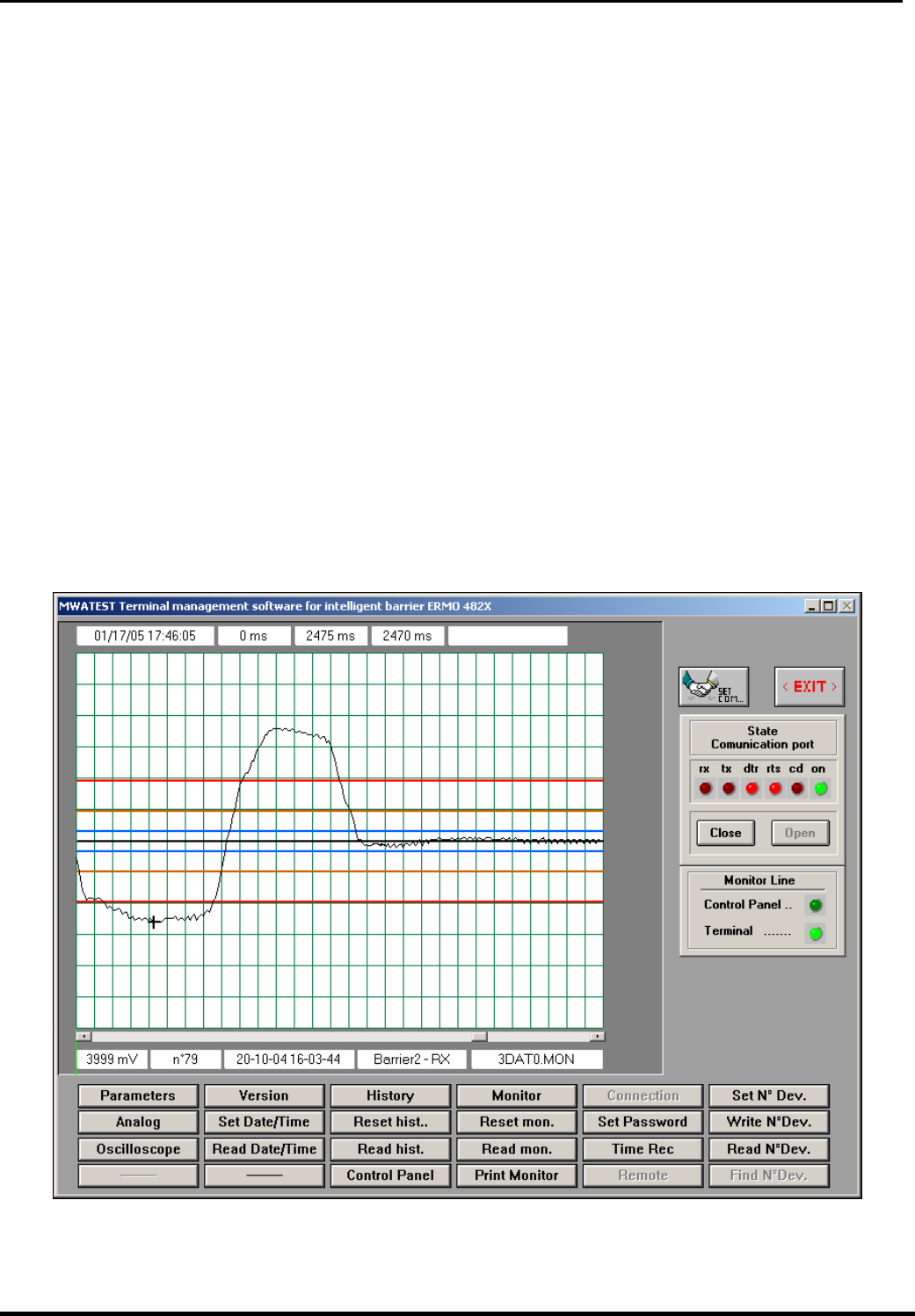
© CIAS Elettronica S.r.l. Ed. 5.0
Installation Handbook page 54 of 59 ERMO 482X PRO
To read the present barrier number selected operate as follow:
• Rotate decimal switch SW3 (tens column) until the first red led (D9) becomes ON .
• Rotate decimal switch SW2 (units column) until the second red led (D10) becomes ON .
The reading values will be included between 01 and 99. The value 00 means barrier 100, this
is the default value, used when a fatal error occurs and the default parameters are
automatically used. To modify the present barrier number it is necessary to set, by means of
the two switches SW3 and SW2 a new value and then push the button S3.
p. On the receiver PCB is provided a balanced input were it’s possible to connect an external
detector and manage its activity trough the head. To activate this function on the RX PCB, it’s
necessary to end the alignment procedure, leaving the function selector in position 9 (balanced
line active) instead of 0 (balanced line inactive). The alignment procedure is closed when the
radome will be closed and the tilt switch results in vertical position.
4.2 Adjustment and Testing with Software
Use a PC with MWATEST CIAS program so as to view and manage all the software parameters
of the barrier, including the analogue levels of the thresholds and of the received signal. The
connections and/or software functions management procedures are specified in this program’s
technical documentation.

© CIAS Elettronica S.r.l. Ed. 5.0
Installation Handbook page 55 of 59 ERMO 482X PRO
5. MAINTENANCE AND ASSISTANCE
5.1 Troubleshooting
In case of false alarm, check the parameters recorded during the Installation phase (on
attached Test Sheet), if there are divergences with permitted limits check again the related
points in chapter "Adjustment and Testing (4)"
Defect Possible Cause Possible Solution
Power Supply 19 V~ or 24V
missing
Check out the Primary and Secondary
power supply of the Transformer
Connections broken Ad just the connections
Main Power supply LED off Tx
and/or Rx
Power Supply circuit broken Change the Electronic board
Power too high or too low Check the battery voltage and the
power supply
Temperature too high or too low Check the temperature of the barrier
Tx Oscillator Fault Change the Oscillator
Fault Led OFF
Tx or Rx failures Change the Electronic board
Movement or obstacles in the
protected field
Check out that the protected field is
free from obstacles and free from
objects and/or person moving.
Barrier not properly aligned Re do the alignment procedure as
described in points: a,b,c,d,e,f,g,h,i of
charter 4.1.2
Wrong channel selections Do again the Channel acknowledge
procedure as described in point j of
charter 4.1.2
Alarm Led OFF
Alarm of sensor connected on
the balanced line input.
Check out the sensor connected to
the balanced line input. If no sensors
are connected ensure to finish the
installation with selector SW3 in
position 0. See chapter 4.1.2 point q,
Barrier not properly aligned Re do the alignment procedure as
described in points: a,b,c,d,e,f,g,h,i of
charter 4.1.2
obstacles in the protected field Remove obstacles
Too low signal transmitted Check the transmitter
Rx circuit fault Change the Rx circuit
High AGC Voltage
Rx MW part fault Change the RX MW part
Micro switch open Check the micro switch position Tamper Led OFF
Tilt bulb in wrong position Check the position of the tilt bulb
BF Oscillator Fault Change the TX circuit Fault Led Off only on TX circuit
MW oscillator Fault Change the MW part
5.2 Maintenance kits
The Maintenance Kits are composed by circuits equipped with microwave cavities, their
substitution is very easy:
Unlock the only one fixing screw and install the new circuit into related plastic guides present on
the bottom box.
The circuit and cavity substitution on boot transmitter and receiver heads doesn’t
changes the heads alignment, and so no new alignment is required

© CIAS Elettronica S.r.l. Ed. 5.0
Installation Handbook page 56 of 59 ERMO 482X PRO
6. CHARACTERISTICS
6.1 Technical characteristics
TECHNICAL CARACTERISTICS Min Nom Max Note
Frequency - 10.525 GHz - -
Maximum power 1.8 W e.i.r.p
Modulation - - - On/off
Duty-cycle - 50/50 - -
Number of channels - - 16 -
Range:
ERMO 482X PRO/50 - 50 m - -
ERMO 482x PRO/80 - 80 m - -
ERMO 482x PRO/120 - 120 m - -
ERMO 482x PRO/200 - 200 m - -
Power supply ( V ∼ ) 17 V 19 V 21 V -
Power supply ( V ) 11,5 V 13,8 V 16 V -
Current absorption TX in surveillance ( mA ∼ ) - 159 - -
Current absorption TX in alarm ( mA ∼ ) - 150 - -
Current absorption RX in surveillance ( mA ∼ ) - 170 - -
Current absorption RX in alarm ( mA ∼ ) - 160 - -
Current absorption TX in surveillance ( mA ) - 80 - -
Current absorption TX in alarm ( mA ) - 73 - -
Current absorption RX in surveillance ( mA ) - 90 - -
Current absorption RX in alarm ( mA ) - 84 - -
Housing for battery - - - 12Vn/1,9A
h
Intrusion alarm contact (TX+RX) - - 100mA C-NC
Radome removal contact (TX+RX) - - 100mA C-NC
Fault contact (TX+RX) - - 100mA C-NC
Intrusion alarm (TX+RX) Green LED ON - - - Rest cond.
Radome removal (TX+RX) Green LED ON - - - Rest cond.
Fault alarm (TX+RX) Green LED ON - Rest cond.
Threshold adjustment - - - On board +
SW
Weight without battery (TX) - 2930 g - -
Weight without battery (RX) - 2990 g - -
Diameter - - 305 mm -
Deep, brackets included - - 280 mm -
Working temperature -40 °C - +65 °C -
Box protection level IP55 - - -

© CIAS Elettronica S.r.l. Ed. 5.0
Installation Handbook page 57 of 59 ERMO 482X PRO
6.2 Functional Characteristics
1) Analysis Signal processing according to behaviour model.
2) Analysis Modulation channel frequency processing (16 channels)
3) Analysis Absolute received signal value processing, To guarantee the S/N optimal value (Low level
signal).
4) Analysis Absolute received signal value processing, for fault detection, behaviour deterioration,
masking.
5) Analysis Signal trend to select various cases of AGC behaviour..
6) Analysis DC Power supply voltage processing (battery charger), High or Low.
7) Analysis AC Power supply voltage processing, Presence or Absence.
8) Analysis Ambient temperature processing, detection of permitted working range
9) Analysis Tampering of Tx and Rx heads.
10) Availability Stand-by input control, for monitor adjustment and historical inhibition, living always active
the alarm status generation.
11) Availability Test input control, to procure on receiver the alarm relay activation in case of positive
result.
12) Availability Auxiliary balanced line allowing connection of additional sensor. Over two connection
conductors between sensor and Tx or Rx head. The capability is to discriminate the
following events: alarm, tamper, fault , line cutting, line short circuit
13) Activation Three static relay output for alarm, tamper, fault on receiver and transmitter.
14) Activation Three signalling LED for alarm, tamper, fault on receiver and transmitter
15) Activation Synchronism signal output of transmitter for the other transmitters synchronization
16) Activation Synchronism signal input on transmitter for the local transmitter synchronization
17) Availability Output terminal block for the battery 12 V/2 Ah connection in case of mains absence.
18) Availability 16 positions switch for modulation channel frequency choice. During the installation phase
the receiver identifies and store automatically which channel must be used during
working phase.
19) Availability Lithium battery on transmitter and receiver for data storage, also in case of power supply
completely OFF
20) Availability Calendar watch on transmitter and receiver, for the event storage timing. Booth for
analogue events monitoring and historical events record.
21) Availability Historical event records on transmitter and receiver, for the last 256 events (RX) 128 (TX)
occurred, with the value (if any), data, time and event types indication. The data
acquisition can be done with MWATEST software, the data will be stored in historical files
(for read and print).
22) Availability Up to 100 event records (2.5 seconds each) stored in receiver memory, related to
detected analogue signal if higher then user preset value (called monitor threshold).
23) Availability A default parameters set, for transmitter and receiver, to use whenever absent or if the
self diagnosis detects a wrong parameter.
24) Availability connector on transmitter and receiver, for external measures
25) Availability P. C. connector on transmitter and receiver, for serial line RS485 connection, used with
software MWATEST for tests, settings and management of barrier.

© CIAS Elettronica S.r.l. Ed. 5.0
Installation Handbook page 58 of 59 ERMO 482X PRO
APPENDICE A
The following is a list of the settings of some modems needed to remotely connect the barriers.
As it can be seen, 2 different settings are provided for each type of modem, i.e., CENTRE
(Operator Terminal which remotely connects the ERMO 482x PRO Barriers) and PLANT (the
RS485 interconnection network of the ERMO 482x PRO Barriers).
Digicom Botticelli 56K V.90 Digicom Leonardo56
Centre:
at&f Load default parameters.
atx3 Engaged tone detection.
at%c3 Compression MNP5 &V.42 bis.
at%e0 Auto-retrain disabled.
at+ms=9,1,9600,9600 Make the connection only at 9600 bps.
at\n3 Error correction V.42 LAPM/MNP.
ate0 Disable echo of controls..
at&w Store parameters..
Plant:
at&f Load default parameters.
atx3 Engaged tone detection.
at%c3 Compression MNP5 &V.42 bis.
at%e0 Auto-retrain disabled.
at+ms=9,1,9600,9600 Make the connection only at 9600 bps.
at\n3 Error correction V.42 LAPM/MNP.
ate0 Disable echo of controls..
ats0=1 Automatic reply after one ring.
at&w Store parameters..
VACF1433VQE
Centre:
at&f Load default parameters.
atx3 Engaged tone detection.
at%c0 Remove compression MNP5 &V.42 bis.
at%e0 Auto-retrain disabled.
at\n5 Error correction MNP.
ate0 Disable echo of controls..
at&w Store parameters..
Plant:
at&f Load default parameters.
atx3 Engaged tone detection.
at%c0 Remove compression MNP5 &V.42 bis.
at%e0 Auto-retrain disabled.
at\n5 Error correction MNP.
ats0=1 Automatic reply after one ring.
ate0 Disable echo of controls..
at&w Store parameters..

© CIAS Elettronica S.r.l. Ed. 5.0
Installation Handbook page 59 of 59 ERMO 482X PRO
56K Modem
Centre:
at&f Load default parameters.
atx3 Engaged tone detection.
at%c3 Compression MNP5 &V.42 bis.
at%e0 Auto-retrain disabled.
at+ms=9,1,9600,9600 Make a connection only at 9600 bps.
at\n3 Error correction V.42 LAPM/MNP.
ate0 Disable echo of controls..
at&w Store parameters..
Plant:
at&f Load default parameters.
atx3 Engaged tone detection.
at%c3 Compression MNP5 &V.42 bis.
at%e0 Auto-retrain disabled.
at+ms=9,1,9600,9600 Make a connection only at 9600 bps.
at\n3 Error correction V.42 LAPM/MNP.
ats0=1 Automatic reply after one ring.
ate0 Disable echo of controls..
at&w Store parameters..
Trust communicator 56K ESP
Centre:
at&f Load default parameters.
atx3 Engaged tone detection.
at%c3 Compression MNP5 &V.42 bis.
at%e0 Auto-retrain disabled.
at\n3 Error correction V.42 LAPM/MNP.
ate0 Disable echo of controls..
at&w Store parameters..
Plant:
at&f Load default parameters.
atx3 Engaged tone detection.
at%c3 Compression MNP5 &V.42 bis.
at%e0 Auto-retrain disabled.
at\n3 Error correction V.42 LAPM/MNP.
ats0=1 Automatic reply after one ring.
ate0 Disable echo of controls..
at&w Store parameters..
MODEM CIAS 9600
Plant:
at&f Load default parameters.
ats0=1 Automatic reply after one ring.
at%c0 No compression MNP5 &V.42 bis.
at%e0 Auto-retrain disabled.
at\n5 Error correction MNP.
ate0 Disable echo of controls..
at&w Store parameters..
Note: the CIAS 485/9600 modem accept the serial line RS485, without the cable cross
connections and the conversion RS485/RS232.
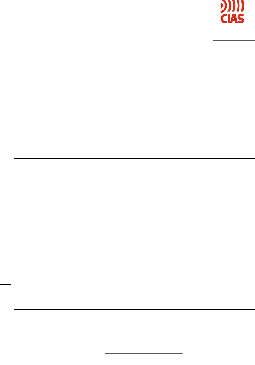
SCHEDA DI COLLAUDO – TEST SHEET
ERMO 482x PRO TX NUMERO DI SERIE
SERIAL NUMBER:
Cliente/Customer
Indirizzo/Address
Barriera /Barrier N°
(*) misura può essere effettuata anche con lo strumento STC 95
(*) It is possible to make the measure also by the STC 95
OSSERVAZIONI DELL’INSTALLATORE – INSTALLER COMMENTS
Data installazione/Installation date
Firma Installatore/Installer Signature
VALORI MISURATI SUL TRASMETTITORE – MEASURED VALUES ON THE TRASMITTER
VALORI MISURATI
MEASURED VALUES
MISURE
MEASUREMENTS
VALORI TIPICI
STANDARD
VALUES INSTALLAZIONE
INSTALLATION MANUTENZIONE
MAINTENANCE
1
TENSIONE DI ALIMENTAZIONE, MISURATA TRA I
PIN 1-2 DI MS1, CON BATTERIA SCOLLEGATA. (*)
SUPPLY VOLTAGE, MEASURED BETWEEN PINS
1-2 OF MS1 WITH BATTERY DISCONNECTED. (*)
13,8 VDC ± 10%
2
TENSIONE DI ALIMENTAZIONE INTERNA
MISURATA TRA IL PIN 16 DI J3 E GND. (*)
INSIDE SUPPLY VOLTAGE MEASURED BETWEEN
PIN 16 OF J3 AND GND. (*)
8 VDC ± 10%
3
TENSIONE DI ALIMENTAZIONE INTERNA,
MISURATA TRA IL PIN 12 DI J3 E GND. (*)
INSIDE SUPPLY VOLTAGE MEASURED BETWEEN
PIN 12 OF J3 AND GND. (*)
5 V ± 10%
4
TENSIONE OSCILLATORE FUNZIONANTE
MISURATA TRA IL PIN 13 DI J3 E GND. (*)
OSCILLATOR OK VOLTAGE MEASURED BETWEEN
PIN 13 OF J3 AND GND. (*)
4 V ± 10%
5
SELEZIONE MASTER/SLAVE
MASTER/SLAVE SELECTION
-
□ MASTER
□ SLAVE
□ MASTER
□ SLAVE
6
CANALE DI MODULAZIONE SELEZIONATO
MODULATION CHANNEL SELECTED
-
□ Ch 0 □ Ch 8
□ Ch 1 □ Ch 9
□ Ch 2 □ Ch A
□ Ch 3 □ Ch B
□ Ch 4 □ Ch C
□ Ch 5 □ Ch D
□ Ch 6 □ Ch E
□ Ch 7 □ Ch F
□ Ch 0 □ Ch 8
□ Ch 1 □ Ch 9
□ Ch 2 □ Ch A
□ Ch 3 □ Ch B
□ Ch 4 □ Ch C
□ Ch 5 □ Ch D
□ Ch 6 □ Ch E
□ Ch 7 □ Ch F
TAGLIARE QUI / CUT HERE
SCHEDA DI COLLAUDO – TEST SHEET
ERMO 482x PRO RX NUMERO DI SERIE
SERIAL NUMBER:
Cliente/Customer
Indirizzo/Address
Barriera /Barrier N°
(*) misura che può essere effettuata anche con lo strumento STC 95
(*) It is possible to make the measure also by the STC 95
OSSERVAZIONI DELL’INSTALLATORE – INSTALLER COMMENTS
t
a
Data installazione/Installation date
Firma Installatore/Installer Signature
VALORI MISURATI SUL RICEVITORE – MEASURED VALUES ON THE RECEIVER
VALORI MISURATI
MEASURED VALUES
MISURE
MEASUREMENTS
VALORI TIPICI
STANDARD
VALUES
INSTALLAZIONE
INSTALLATION MANUTENZIONE
MAINTENANCE
1
TENSIONE DI ALIMENTAZIONE, MISURATA TRA I
PIN 1-2 DI MS1, CON BATTERIA SCOLLEGATA. (*)
SUPPLY VOLTAGE, MEASURED BETWEEN PINS
1-2 OF MS1 WITH BATTERY DISCONNECTED. (*)
13,8 VDC ± 10%
2
TENSIONE DI ALIMENTAZIONE INTERNA,
MISURATA TRA IL PIN 12 DI J3 E GND. (*)
INSIDE SUPPLY VOLTAGE MEASURED BETWEEN
PIN 12 OF J3 AND GND. (*)
5 VDC ± 10%
3
TENSIONE DI RAG, MISURATA TRA IL PIN 14 DI J3
E GND. (*)
AGC VOLTAGE MEASURED BETWEEN PIN 14 OF
J3 AND GND. (*)
2,5 ÷ 6 VDC
4
VERIFICA SEGNALE RIVELATO, MISURATA CON
LO STRUMENTO STC 95.
SIGNAL DETECTED VOLTAGE MEASURED BY
STC 95.
6 VDC ± 10%
STABILE
STEADY
5
CANALE DI MODULAZIONE UTILIZZATO
MODULATION CHANNEL USED
-
□ Ch 0 □ Ch 8
□ Ch 1 □ Ch 9
□ Ch 2 □ Ch A
□ Ch 3 □ Ch B
□ Ch 4 □ Ch C
□ Ch 5 □ Ch D
□ Ch 6 □ Ch E
□ Ch 7 □ Ch F
□ Ch 0 □ Ch 8
□ Ch 1 □ Ch 9
□ Ch 2 □ Ch A
□ Ch 3 □ Ch B
□ Ch 4 □ Ch C
□ Ch 5 □ Ch D
□ Ch 6 □ Ch E
□ Ch 7 □ Ch F
TAGLIARE QUI / CUT HERE

NOTE:

-This device complies with Part 15 of the FCC Rules and with RSS-210 of Industry Canada.
Operation is subject to the following two conditions. (1) this device may not cause harmful
interference, and (2) this device must accept any interference received, including
interference that may cause undesired operation.
- This equipment has been tested and found to comply with the limits for a Class B digital
device, pursuant to Part 15 of the FCC Rules. These limits are designed to provide
reasonable protection against harmful interference in a residential installation. This
equipment generates, uses and can radiate radio frequency energy and, if not installed and
used in accordance with the instructions, may cause harmful interference to radio
communications. However, there is no guarantee that interference will not occur in a
particular installation. If this equipment does cause harmful interference to radio or
television reception, which can be determined by turning the equipment off and on, the user
is encouraged to try to correct the interference by one or more of the following measures:
• Reorient or relocate the receiving antenna.
• Increase the separation between the equipment and receiver.
• Connect the equipment into an outlet on a circuit different from that to which the receiver
is connected.
• Consult the dealer or an experienced radio/TV technician for help.
- Warning: Changes or modifications made to this equipment not expressly approved by
CIAS Elettronica may void the FCC authorization to operate this equipment.
-IMPORTANT NOTE:
FCC Radiation Exposure Statement:
This equipment complies with FCC radiation exposure limits set forth for an uncontrolled
environment. This equipment should be installed and operated with minimum distance of
20cm between the radiator and your body.
This transmitter must not be co-located or operating in conjunction with any other antenna
or transmitter.
© Copyright CIAS Elettronica S.r.l.
Stampato in Italia / Printed in Italy
CIAS Elettronica S.r.l.
Direzione, Ufficio Amministrativo, Ufficio Commerciale, Laboratorio di Ricerca e Sviluppo
Direction, Administrative Office, Sales Office, Laboratory of Research and Development
20158 Milano, via Durando n. 38
Tel. +39 02 376716.1
Fax +39 02 39311225
Web-site: www.cias.it
E-mail: cias.elettronica@cias.it
Stabilimento / Factory
23887 Olgiate Molgora (LC), Via Don Sturzo n. 17