CIG WF0613A 2.4GHz&5GHz 3x3 Outdoor AP User Manual WF 0613A
CIG SHANGHAI CO., LTD. 2.4GHz&5GHz 3x3 Outdoor AP WF 0613A
CIG >
Contents
- 1. user maual
- 2. users manual
user maual

WF-0613AUserManual
8th Oct, 2013
VERSION 1
C
AMBRIDGE
Industries (Group) Co Ltd.
CIG
C
AMBRIDGE
Industries (Group) Co Ltd.
CIG

Notice
CIGhasthesolerighttomakecorrections,modifications,enhancements,improvements,andotherchangestoitsproductsandservicesatany
timeandtodiscontinueanyproductorservicewithoutnotice,CIGhasthefinalinterpretation.Thisversioniseffectiveinthetwomonthssincethe
releasedate.
TABLE OF CONTENTS
1Safety ........................................................................................................................... 3
2Overview ...................................................................................................................... 3
3Installation of device .................................................................................................... 6
3.1Installation tools and environment ............................................................................................. 6
3.2Installation Steps ....................................................................................................................... 6
4Indicators ..................................................................................................................... 8
5Thin AP mode basic configuration ............................................................................... 9
5.1Login to the Web interface and setting from FAT AP mode ..................................................... 9
5.2Login to the Web interface and setting from Thin AP mode ................................................... 11
6Thin AP uplink debug mode ....................................................................................... 12

Notice
CIGhasthesolerighttomakecorrections,modifications,enhancements,improvements,andotherchangestoitsproductsandservicesatany
timeandtodiscontinueanyproductorservicewithoutnotice,CIGhasthefinalinterpretation.Thisversioniseffectiveinthetwomonthssincethe
releasedate.
1 Safety
Do not install the device near the power line, electric lamp, power grid, or in any
forceful power grid place, which is to avoid the AP abnormal work.
Ensure the power adapter is grounded well if install the device indoor.
Install other lightning protection equipment near the device if necessary,
because the limitation of lightning protection module inside the device is 6KV.
Use the steady power grid to provide the power to the device, which is to avoid
the abnormal work.
Use a less than 100m network cable to connect the PoE port, which is to acquire
the steady power. The network cable complies with the DC resistance definition
in the YD/926.2 protocol.
2 Overview
This document is used to describe the operation instruction of WF-0613A.
WF-0613A is a multifunctional outdoor wireless access point product. It is mainly used
for carriers to provide stable outdoor Wi-Fi coverage and long distance wireless
backhaul, to achieve high-quality, stable and convenient broadband service. It
provides the most economical and effective way for last 1 km solution.
Having perfect compatibility, WF-0613A works with most wireless terminals and CPEs
to builds a high capacity Wi-Fi system, which provides a solution of the fastest return
on investment (ROI) for the operators.
WF-0613A has some perfect features like excellent performance, powerful function,
flexible pattern, convenient installation and so on.
Notice
CIGhasthesolerighttomakecorrections,modifications,enhancements,improvements,andotherchangestoitsproductsandservicesatany
timeandtodiscontinueanyproductorservicewithoutnotice,CIGhasthefinalinterpretation.Thisversioniseffectiveinthetwomonthssincethe
releasedate.
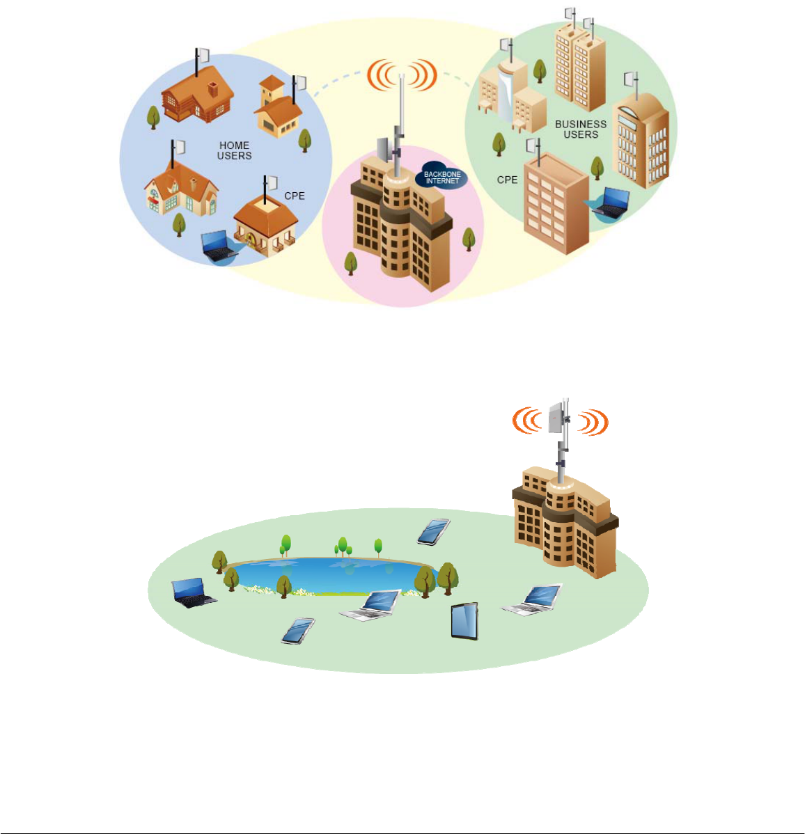
Figure 1
Network Application for indoor coverage
Figure 1
Network Application for cellular coverage
Notice
CIGhasthesolerighttomakecorrections,modifications,enhancements,improvements,andotherchangestoitsproductsandservicesatany
timeandtodiscontinueanyproductorservicewithoutnotice,CIGhasthefinalinterpretation.Thisversioniseffectiveinthetwomonthssincethe
releasedate.
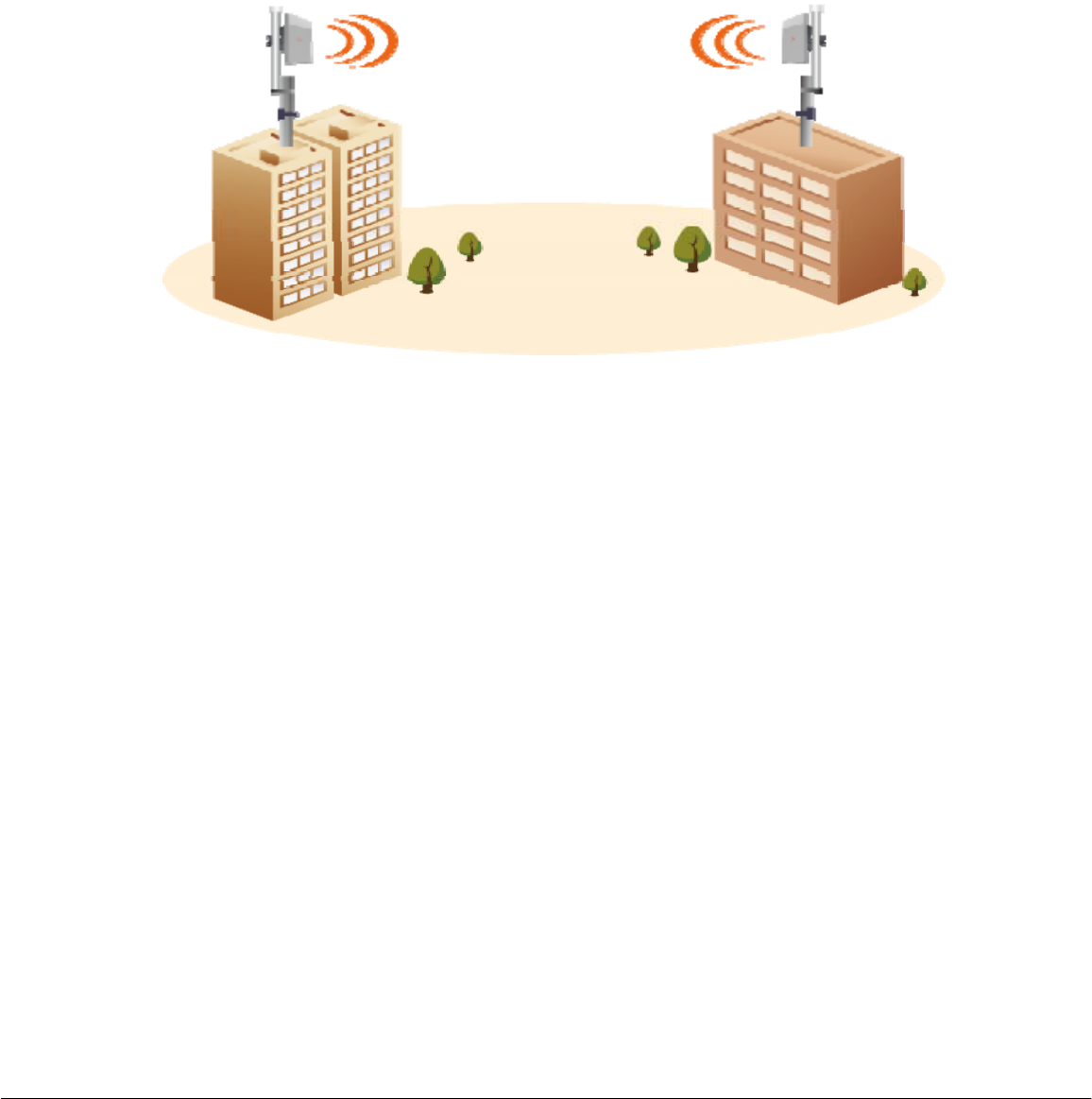
Figure 2
Network Application for wireless bridge
Notice
CIGhasthesolerighttomakecorrections,modifications,enhancements,improvements,andotherchangestoitsproductsandservicesatany
timeandtodiscontinueanyproductorservicewithoutnotice,CIGhasthefinalinterpretation.Thisversioniseffectiveinthetwomonthssincethe
releasedate.
3 Installation of device
3.1 Installation tools and environment
Installation tools: A laptop, super category5 outdoor network cables, a screwdriver,
two wrenches, screws and a pole (optional).
Installation environment: Need to ensure that it is visible between the AP and
terminals and no tall obstacles between them.
3.2 Installation Steps
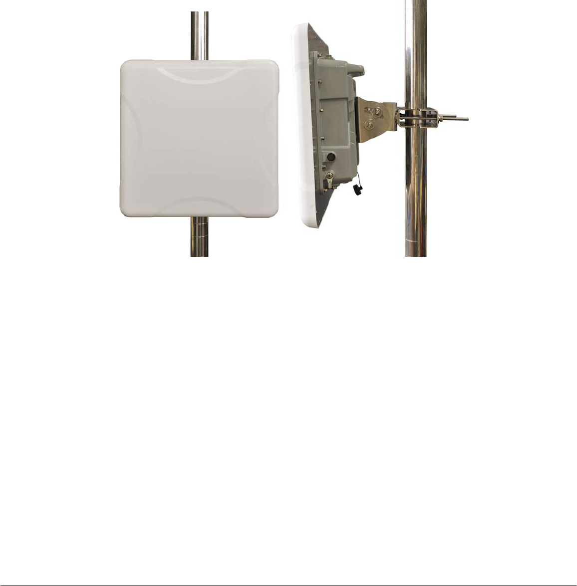
1. Mount the AP on the pole, and should confirm AP is fixed well. Use one RJ45
cable or SFP to connect the AP POE port.
Figure4 Ports of the WF-0613A
Notice
CIGhasthesolerighttomakecorrections,modifications,enhancements,improvements,andotherchangestoitsproductsandservicesatany
timeandtodiscontinueanyproductorservicewithoutnotice,CIGhasthefinalinterpretation.Thisversioniseffectiveinthetwomonthssincethe
releasedate.
Figure5 Pole mounting
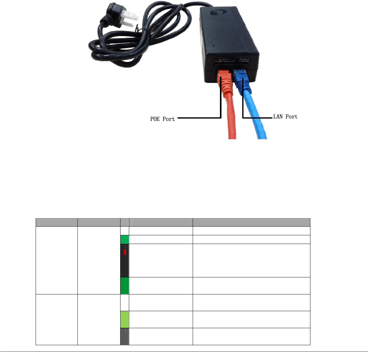
2. Connect the WAN POE port of the WF-0613A and the POE port of the adaptor by
a network cable, and connect the LAN port of the adaptor and another network
device (Laptop, switch etc.) by another network cable (or optical fiber). And then
power on the adapter.
Check the status of indicators of the WF-0613A. The detail Indicators refer to
Figure 7.
Notice
CIGhasthesolerighttomakecorrections,modifications,enhancements,improvements,andotherchangestoitsproductsandservicesatany
timeandtodiscontinueanyproductorservicewithoutnotice,CIGhasthefinalinterpretation.Thisversioniseffectiveinthetwomonthssincethe
releasedate.
Figure6 Ports of the adaptor
Note:
The longest length of the network cable plugged in to the POE port is up to 100m, and
the network cables should comply with the YD/926.2 protocol.
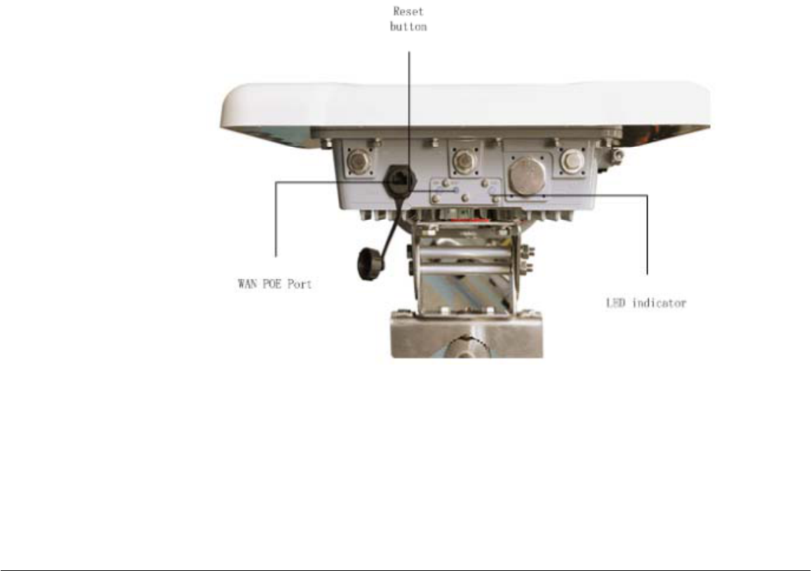
4 Indicators
Figure7 Indicators
LED Color Status Description
Run Green or
Red
Off Powered off
Solid Powered on Correctly
Fast
Blinking(1Hz)
Failure on Power on self-test
(Self test includes checking
CPU, flash, DDR, RF radio,
Ethernet)
Slow Blinking
( 4Hz )
Thin AP Mode, AP is
Registered at AC
Ethernet Green
Off None Ethernet Connection is
available
Solid Any Ethernet Connection is
available
Blinking Any Ethernet Connection has
data

Notice
CIGhasthesolerighttomakecorrections,modifications,enhancements,improvements,andotherchangestoitsproductsandservicesatany
timeandtodiscontinueanyproductorservicewithoutnotice,CIGhasthefinalinterpretation.Thisversioniseffectiveinthetwomonthssincethe
releasedate.
5 Thin AP mode basic configuration
Note:
When do the thin AP settings, make sure the AP mode first, and then select the appropriate
method to do the basic setting.
5.1
Login to the Web interface and setting from FAT AP mode
1. Power on WF-0613A, and connect the LAN port (refer to Figure 6) to laptop;
2. Set the laptop wired NIC IP address to 192.168.188.X (X is an any number except
251 and 255), and the subnet mask is set to 255.255.255.0. Figure 8 is a dialog
box for modifying local area connection properties in the Windows 7 system.
Figure8 Properties of Internet protocol (TCP/IP)
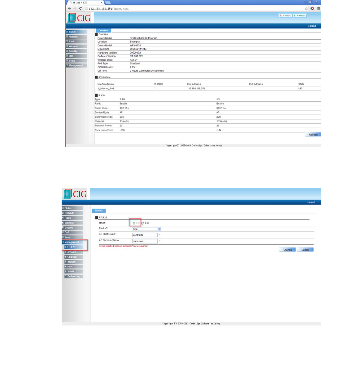
3. Input the default IP address “192.168.188.251”in the address bar of browser. Then
enter the default username and password (username: admin, password: password)
to enter the Web interface.
Notice
CIGhasthesolerighttomakecorrections,modifications,enhancements,improvements,andotherchangestoitsproductsandservicesatany
timeandtodiscontinueanyproductorservicewithoutnotice,CIGhasthefinalinterpretation.Thisversioniseffectiveinthetwomonthssincethe
releasedate.
Figure9 Web interface
4. In the Web interface, Select “Management” tab, then select “FIT/FAT” in the left-
hand navigation tree, to do the setting. Select “FIT” in the “Mode” option.
Figure10 FIT AP setting
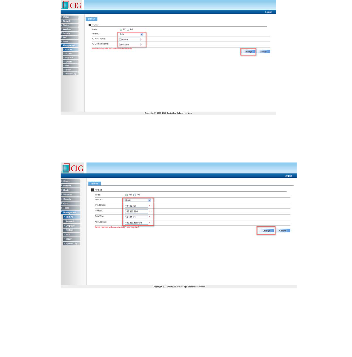
5. Here are two options in “Find AC”, “Auto” and “Static”.
i. If you select “Auto” mode, AP will use DHCP to get IP address from AC.
Before you active the function, you should setting the AC host name and
domain name. If no AC information to fill in, just jump and click “Change”
button
Notice
CIGhasthesolerighttomakecorrections,modifications,enhancements,improvements,andotherchangestoitsproductsandservicesatany
timeandtodiscontinueanyproductorservicewithoutnotice,CIGhasthefinalinterpretation.Thisversioniseffectiveinthetwomonthssincethe
releasedate.
Figure11 Find AC in auto mode
ii. if you select “Static” mode. AP will use static IP register AC. Fill in AP
static IP, Mask, Gateway and AC IP address is a MUST. Then click the
change” button.
Figure12 Find AC in static mode
5.2
Login to the Web interface and setting from Thin AP mode
1. Power on WF-0613A;
2. Set the user computer wireless NIC IP address to 192.168.188.X (X is an any
number except 251 and 255), and the subnet mask is set to 255.255.255.0. The
method is the same as 5.1 step 1.
3. When the AP does not register with AC, AP will broadcast a SSID to help user
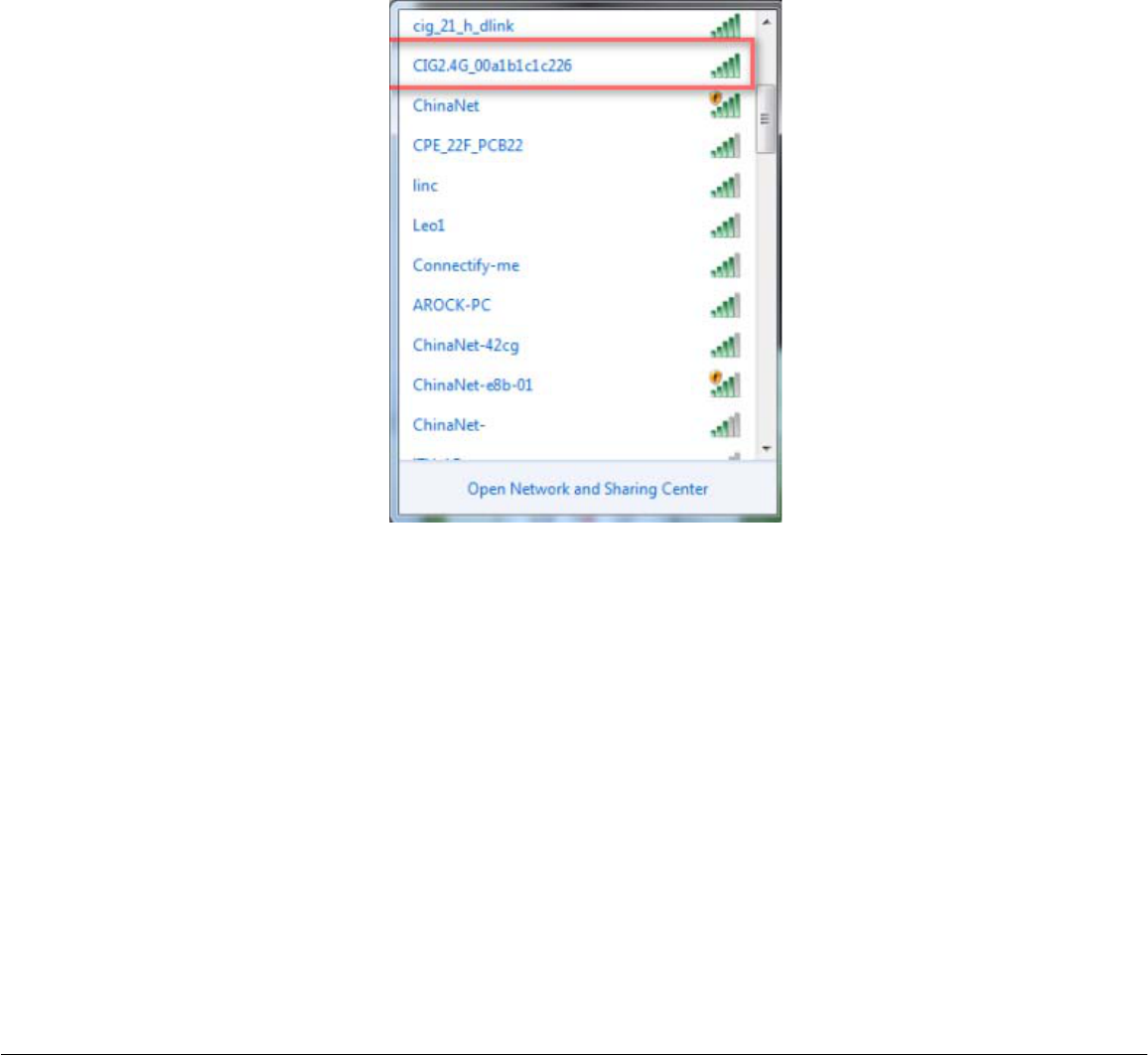
Notice
CIGhasthesolerighttomakecorrections,modifications,enhancements,improvements,andotherchangestoitsproductsandservicesatany
timeandtodiscontinueanyproductorservicewithoutnotice,CIGhasthefinalinterpretation.Thisversioniseffectiveinthetwomonthssincethe
releasedate.
connect. The SSID is named as “CIG2.4G_xxxxxxxxxxxx” in 2.4 GHz or
“CIG5.8G_xxxxxxxxxxxx” in 5.8 GHz (the “xxxxxxxxxxxx” is the MAC address of
AP) and it is encrypted as WPA/PSK. Use Windows wireless tool to connect the
SSIDs with password “CIGW8888”.
Figure13 Thin AP SSID broadcast
4. After connect with AP SSID, input the default IP address “192.168.188.251”in the
address bar of browser. Then enter the default username and password
(username: admin, password: password) to enter the Web interface.
5. If you need to change the AP configuration, please follow 5.1 step 3 and step 4.
6 Thin AP uplink debug mode
1. In the field, some problems may cause AP disconnect with AC. When AP under
this situation, it can provide an uplink debug method to help engineer do the
trouble shooting.
2. When AP disconnect with AC, AP will broadcast SSIDs in both 2.4 GHz and 5.8
GHz. The SSID is named as “CIG2.4G_xxxxxxxxxxxx” or “CIG5.8G_xxxxxxxxxxxx”
(the “xxxxxxxxxxxx” is the MAC address of AP) and it is encrypted as WPA/PSK.
Use Windows wireless tool to connect the SSIDs with the same password
“CIGW8888”.

Notice
CIGhasthesolerighttomakecorrections,modifications,enhancements,improvements,andotherchangestoitsproductsandservicesatany
timeandtodiscontinueanyproductorservicewithoutnotice,CIGhasthefinalinterpretation.Thisversioniseffectiveinthetwomonthssincethe
releasedate.
3. Before connect with the SSID, PC wireless NIC should be set as static IP ( the
procedure is the same as 5.1 step 1), then it can connect with AP and use telnet
or Web to catch all the information we need.

Notice
CIGhasthesolerighttomakecorrections,modifications,enhancements,improvements,andotherchangestoitsproductsandservicesatany
timeandtodiscontinueanyproductorservicewithoutnotice,CIGhasthefinalinterpretation.Thisversioniseffectiveinthetwomonthssincethe
releasedate.
Federal Communications Commission (FCC) Interference Statement
This equipment has been tested and found to comply with the limits for a Class B digital device, pursuant
to Part 15 of the FCC Rules.
These limits are designed to provide reasonable protection against harmful interference in a residential
installation. This equipment generate, uses and can radiate radio frequency energy and, if not installed
and used in accordance with the instructions, may cause harmful interference to radio communications.
However, there is no guarantee that interference will not occur in a particular installation. If this
equipment does cause harmful interference to radio or television reception, which can be determined by
turning the equipment off and on, the user is encouraged to try to correct the interference by one of the
following measures:
Reorient or relocate the receiving antenna.
Increase the separation between the equipment and receiver.
Connect the equipment into an outlet on a circuit different from that to which the receiver is
connected.
Consult the dealer or an experienced radio/TV technician for help.
This device complies with Part 15 of the FCC Rules. Operation is subject to the following two conditions:
(1) This device may not cause harmful interference, and (2) this device must accept any interference
received, including interference that may cause undesired operation.
FCC Caution: Any changes or modifications not expressly approved by the party responsible for
compliance could void the user’s authority to operate this equipment.
RF exposure warning
This device generates and radiates radio-frequency energy. In order to comply with FCC radio-frequency
exposure guidelines for an uncontrolled environment, this equipment must be installed and operated
while maintaining a minimum body to antenna distance of 20 cm (approximately 8 in.)
The equipment must not be co-located or operating in conjunction with any other antenna or transmitter.
For indoor use: the equipment is with frequency band in 5150-5250 MHz.
For fixed point-to point operation: the equipment is with frequency band in 5725-5850 MHz