CIG WF180 2x2 dual band 802.11ac indoor AP User Manual
CIG SHANGHAI CO., LTD. 2x2 dual band 802.11ac indoor AP Users Manual
CIG >
Contents
- 1. Users Manual
- 2. User Manual
Users Manual

WF-180 Wireless Access Point

Thank you for buying this product. The following information aims to give you general
information about product introduction, product overview and installation procedure and
so on.
1. Introduction
WF-180 is a dual-band 2x2streams and chains indoor Wi-Fi AP, which is complied with the
IEEE802.11n standard and designed for high-density deployments in offices, schools,
hospitals and hotels that require premium performance.
Having together MIMO (Multiple-in&Multiple-out) technology with high-throughput mode
techniques, WF-180 works with most wireless terminals to builds a high capacity Wi-Fi
network.
2. Package List
• AP x1
• Wall bracket x1
• Ceiling bracket x 1
• Screw x1
• Cable tie x1
3. Product Overview
No.
Name
Function
LEDs
See LED Definition
LAN Port
10/100/1000M Base-T Ethernet ports (RJ-45), used as a
WAN port and used for being powered by PoE function.
带格式的: 缩进: 左侧: 0 厘米
带格式表格
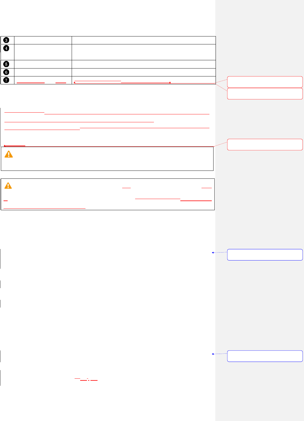
Console port
Also names as RJ-11, used to manage WF-180 software.
Reset button
Pressing the button longer than 5s to restore the device to
factory defaults and reset the device.
DC power connector
used for connecting the power adapter
USB port
supports a USB 2.0 connector(Support up to 0.5A)
Kensington Lock Slot
What is the function?For additional security
4. Installation
Before you start, To reduce the risk of bodily injury, electrical shock, fire, and equipment
Damage, read all warnings and precautions in this guide before
Installing or maintaining product.read all caution and safety statement in this document.
Caution
To avoid risk of injury from electrical shock or energy hazard, installation and service
of this product must be performed by qualified service personnel.
Make sure the AP fits securely on the ceiling tile rail when hanging the device from
inthe ceiling, because poor installation could cause it to fall onto the peoplefall and make
body injury and equipment damage.
Safety Statement
• To avoid the abnormal work, do not install the device near the power line,
electric lamp, power grid, or in any forceful power grid place
• Ensure the power adapter is grounded well if install the device indoor.
• Install other lightning protection equipment near the device if necessary,
because the lightning protection module inside the device is basic.
• Use the steady power grid to provide the power to the device, which is to avoid
the abnormal work.
• Use a less than 50m network cable to connect the PoE port, which is to acquire
the steady power. The network cable complies with the DC resistance
definition in the YD/926.2 protocol.
Installation Environment
• Operating ambient temperature: 0℃ ~ 45℃
• Operating ambient humidity: 5% ~ 95% non-condensing
Installation mode:
• Wall mounting and ceCelilingmounting.
带格式的: 字体: 非加粗, 字体颜
色: 自动设置
带格式的: 字体: (中文) 宋体, 非
加粗, 字体颜色: 自动设置
带格式的: 字体: 小四, 字体颜色:
浅蓝
带格式的: 段落间距段前: 0.5 行,
段后: 0.5 行
带格式的: 段落间距段前: 0.5 行,
段后: 0.5 行

Installation tool:
• Screws and screw-driver
Installation site:
Please ensure the visibility of product and no tall buildings and woods block
between them.
Installation procedure
Wall mounting
1. Drive two screws fist in the wall. The distantbetween two screws mounted on
the wall is 40mm.
2. Align bracket with the screw, and then pull down the bracket with up to down
direction until it has been fixed tightly.
带格式的: 段落间距段前: 0.5 行,
段后: 0.5 行
带格式的: 段落间距段前: 0.5 行,
段后: 0.5 行
带格式的: 段落间距段前: 0.5 行,
段后: 0.5 行
带格式的: 字体: (默认) Arial,
(中文) 宋体, 小四

3. Align the securing slothookof AP with bracket, and push AP from up to down until
it has been lockedsecured fully.
Ceiling mounting:
1. Fasten ceiling rails by pushing bracket as the indicated direction
带格式的: 段落间距段前: 0.5 行,
段后: 0.5 行
带格式的: 字体: (默认) +西文正
文, (中文) +中文正文, 五号

2. Secure the screw to fasten bracket assembly. Bracket configures two screw
holes, select one of them to fit ceiling rails.
2.
3. Align securingslot hook of AP with bracket (see dotted line), and then push AP
close to bracket until AP has been fullyfastenedlocked.
带格式的: 列出段落, 左, 编号 +
级别: 1 + 编号样式: 1, 2, 3, …
+ 起始编号: 1 + 对齐方式: 左侧
+ 对齐位置: 0.75 厘米 + 缩进位
置: 1.49 厘米
带格式的: 列出段落, 左, 缩进:
左侧: 1.49 厘米

4. Go through locking holes by cable-tie to safely content AP with bracket
5. LED Definition
LED
Function
State-Color
Indication
RUN
AP power / ready status
Steady - Green
APis ready
Flashing - Green
AP is managed by controller
Red
AP hardware failure
Off
No power to AP
LAN
Network Link Status
Steady - Green
1000Mbps Ethernet link negotiated
Steady- Yellow
Reserved for link speed (NIB in PCB)
Flashing
Ethernet link activity
Off
Ethernet link unavailable
5G
5G Hz Radio Status
Steady– Green
5G Hz radio enabled in HT WLAN
mode

Off
5G Hz radio disabled
2.4G
2.4G Hz Radio Status
Steady – Green
2.4G Hz radio enabled in HT WLAN
mode
Off
2.4G Hz radio disabled
6. Software Installation
Logging in to the Web Page
1. To configure PC IP address, fill 192.168.188.x in “IP address” and 255.255.255.0
in “Subnet mask”(set Window7 as an example to show the properties)
2. Input the default IP address 192.168.188.251 in the address bar of the web
browser and press Enter.
3. Enter username and password (username: admin, password: password), after
password authentication is successful, the web page is displayed.
7. Product Specification
Physical specification
Dimensions
160 mm x 160 mm x 40mm(Width x Length x Height)
Weight
Less than 1kg
LEDs
RUN,LAN,5GHz,2.4GHz

Ethernet interface
RJ-45 connector
Electrical specification
Power input
+12V/1A
Power consumption
≤12W
Environmental specification
Working temperature
0℃ ~ 45℃
Working humidity
5% ~ 95% non-condensing
Elevations
86kPa~106kPa
Dustproof and waterproof
IP30
Lightning protection
4KV common mode surge
8. Product Proper Disposal
Waste of Electrical and Electronic Equipment
Directive 2002/96EC on Waste of Electrical and Electronic Equipment are designed
to tackle the fast increasing waste stream of electrical and electronic equipment and
complements European Union measures on landfill and incineration of waste. CIG
products at end of life are subject to separate collection and treatment in the EU Member
Statues and therefore are marked with the symbol.
European Union RoHS
EU Restriction and Hazardous Substances Directive 2011/65/EC (RoHS) restricts
the use of specific hazardous materials in manufacture of electrical and electronic
equipment. Specially, restricted materials are Lead, Cadmium, Mercury, Hexavalent
Chromium, and Bromine. CIG products comply with this requirement and all marked with
“RoHS” shown at the left.
China RoHS
WF-180 AP complies with China environmental declaration requirements and is labeled
with “EFUP 20” label shown as follows.

有毒有害物质声明
Hazardous Materials Declaration
部件名称
(Parts)
有毒有害物质或元素(Hazardous Substance)
铅
(
P
b
)
汞
(
H
g
)
镉
(
C
d
)
六价铬
(
C
r6
+
)
多溴联苯
(
P
BB
)
多溴二苯醚
(
P
B
D
E
)
电路模块
(circuit modules)
×
O
O
O
O
O
电缆及电缆组件
(Mechanicalassembli
es)
x
O
O
O
O
O
金属部件
(Metal Parts)
O
O
O
O
O
O
塑料和聚合物部件
(Plastic and
Polymeric Parts)
O
O
O
O
O
O
O:
表示该有毒有害物质在该部件所有均质材料中的含量在 SJ/T11363 - 2006标准规定的限量要求下。
Indicates that the concentration of the hazardous substance in all homogeneous materials in the parts
is below the relevant threshold of the SJ/T11363-2006 standard.
X:
表示该有毒有害物质至少在该部件的某一均质材料中的含量超出SJ/T11363-2006标准规定的限量要求。
Indicates that the concentration of the hazardous substance of at least one of all homogeneous
materials in the parts is above the relevant threshold of the SJ/T11363-2006 standard.
对销售之日的所售产品,本表显示剑桥公司供应链的电子信息产品可能包含这些物质。注意:在所售产
品中可能会也可能不会含有所有所列的部件。
This table shows where these substances may be found in the supply chain of CIG electronic
information products, as of the date of sale of the enclosed product. Note that some of the component
types listed above may or may not be a part of the enclosed product.
9. Safety and Regulatory compliance
除非另外特别的标注,此标志为针对所涉及产品的环保使用期标志。某些零部件会有一个不同的环
保使用期贴在其产品上。此环保使用期限只适用于产品是在产品手册中规定的条件下工作。
The Environment-Friendly Use Period (EFUP) for all enclosed products and their parts are per the
symbol shown here, unless otherwise marked. Certain parts may have a different EFUPand so are
marked to reflect such. The Environment-Friendly Use Period is valid only when the product is
operated under the conditions defined in the product manual.

9.
WF-180 AP has been tested and complied with the standards as follows:
• FCC DOC Part 15 Class B (US)
• FCC Part 15 Subpart C 15.247 (US)
• FCC Part 15 Subpart E 15.407 (US)
• CE marked with NB letter of opinion for:
• ETSI EN 300 328 (2.4GHz)
• ETSI EN 301 893 (5GHz)
• CB with IEC/EN 60950-1 (Basic safety certificate for worldwide marketing)
10. FAQs
FAQ
Solution
The RUN indicator is off.
Check that the power adapter is plugged into a live AC outlet.
Check the power cable for shorts or breaks.
Check whether the connection between the LAN/POE port of the
combiner and the LAN/POE port is correct.
The LAN port indicator is
off.
Check whether the connection between the LAN/POE port
of the combiner and the LAN/POE port is correct.
11. Technical Support
CIG offers technical support 24 hours a day, 7 days a week. Use one of the following
methods to contact CIG technical assistance center:
Hotline: +86 21 6192 1930
Email: support@cambridgeig.com
12. Contact Information
Hong Kong
25th Floor, Jar dine House, 1 Connaught Place
Hong Kong, PRC
Phone: +852 2827 1778
Shanghai
22F, IliaBuilding
带格式的: 缩进: 左侧: 0.74 厘
米, 无项目符号或编号
带格式的: 段落间距段前: 0.5 行,
段后: 0.5 行
带格式的: 段落间距段前: 0.5 行,
段后: 0.5 行

889Yichang Road
Shanghai 200233, China
Phone: +86 21 61921930
Fax: +86 21 6192 1929
USA
Cambridge Industries Group
Techmart Center 5201 Great
America Parkway, Suite 320
Santa Clara CA 95054.
Tel: +1 408.730.6888
13. Legal declaration
CIG name, CIG logo, and all CIG product names are trademarks of Cambridge Industries
Group Co. Ltd (CIG). All other brand and product names are claimed as property of others
respective holders. Specifications, products, and products names are subject to change
without notice. Copyright
This document may not be reproduced in whole or in part without the express written
permission of CIG. This document contains confidential, proprietary information belonging
to CIG, and may not be used or disclosed except in accordance with applicable
agreements.
Performance figures and data quoted in this document are typical and must be specifically
confirmed by CIG before they become applicable to any particular order or contract. The
company reserves the right to make alterations or amendments to the detailed
specification at its discretion.
Copyright© 2014, Cambridge Industries Group Co. Ltdconfidential, All rights reserved.
Federal Communications Commission (FCC) Interference Statement
This equipment has been tested and found to comply with the limits for a Class B digital
device, pursuant to Part 15 of the FCC Rules.
These limits are designed to provide reasonable protection against harmful interference in
a residential installation. This equipment generate, uses and can radiate radio frequency
energy and, if not installed and used in accordance with the instructions, may cause
harmful interference to radio communications.
However, there is no guarantee that interference will not occur in a particular installation. If
this equipment does cause harmful interference to radio or television reception, which can
be determined by turning the equipment off and on, the user is encouraged to try to correct
the interference by one of the following measures:
Reorient or relocate the receiving antenna.
Increase the separation between the equipment and receiver.
Connect the equipment into an outlet on a circuit different from that to which the
receiver is connected.
Consult the dealer or an experienced radio/TV technician for help.
This device complies with Part 15 of the FCC Rules. Operation is subject to the following
two conditions:
(1) This device may not cause harmful interference, and (2) this device must accept any
interference received, including interference that may cause undesired operation.
FCC Caution: Any changes or modifications not expressly approved by the party
responsible for compliance could void the user’s authority to operate this equipment.
RF exposure warning
This equipment complies with FCC radiation exposure limits set forth for an uncontrolled
environment.
This equipment must be installed and operated in accordance with provided instructions
and the antenna(s) used for this transmitter must be installed to provide a separation
distance of at least 20 cm from all persons and must not be collocated or operating in
conjunction with any other antenna or transmitter.
带格式的: 段前分页
带格式的: 缩进: 悬挂缩进: 1.92
字符, 左 -2.02 字符, 首行缩进:
-1.92 字符

IC Radiation Exposure Statement for Canada
This device complies with Industry Canada licence-exempt RSS standard(s). Operation is
subject to the following two conditions: (1) this device may not cause interference, and (2)
this device must accept any interference, including interference that may cause undesired
operation of the device.
Le présent appareil est conforme aux CNR d'Industrie Canada applicables aux appareils
radio exempts de licence. L'exploitation est autorisée aux deux conditions suivantes : (1)
l'appareil ne doit pas produire de brouillage, et (2) l'utilisateur de l'appareil doit accepter
tout brouillage radioélectrique subi, même si le brouillage est susceptible d'en
compromettre le fonctionnement.
Under Industry Canada regulations, this radio transmitter may only operate using an
antenna of a type and maximum (or lesser) gain approved for the transmitter by Industry
Canada. To reduce potential radio interference to other users, the antenna type and its gain
should be so chosen that the equivalent is otropically radiated power (e.i.r.p.) is not more
than that necessary for successful communication.
Conformément à la réglementation d'Industrie Canada, le présent émetteur radio peut
fonctionner avec une antenne d'un type et d'un gain maximal (ou inférieur) approuvé pour
l'émetteur par Industrie Canada. Dans le but de réduire les risques de brouillage
radioélectrique à l'intention des autres utilisateurs, il faut choisir le type d'antenne et son
gain de sorte que la puissance isotrope rayonnée équivalente (p.i.r.e.) ne dépasse pas
l'intensité nécessaire à l'établissement d'une communication satisfaisante.
User manuals for transmitters equipped with detachable antennas shall also contain the
following notice in a conspicuous location:
This radio transmitter (identify the device by certification number, or model number if
Category II) has been approved by Industry Canada to operate with the antenna types
listed below with the maximum permissible gain and required antenna impedance for each
antenna type indicated. Antenna types not included in this list, having a gain greater than
the maximum gain indicated for that type, are strictly prohibited for use with this device.
Le présent émetteur radio (identifier le dispositif par son numéro de certification ou son
numéro de modèle s'il fait partie du matériel de catégorie I) a été approuvé par Industrie
Canada pour fonctionner avec les types d'antenne énumérés ci-dessous et ayant un gain
admissible maximal et l'impédance requise pour chaque type d'antenne. Les types
d'antenne non inclus dans cette liste,ou dont le gain est supérieur au gain maximal indiqué,
sont strictement interdits pour l'exploitation de l'émetteur.
IMPORTANT NOTE:
Radiation Exposure Statement:
This equipment complies with “Industry Canada RSS-102 for radiation exposure limits set

forth for an uncontrolled environment”.
This equipment should be installed and operated with minimum distance 20cm between the
radiator and your body.