CNet Technology 0232USB611 Wireless USB Adapter User Manual USB Adapter User s Guide
CNet Technology Inc Wireless USB Adapter USB Adapter User s Guide
Contents
- 1. Users manual 1
- 2. Users manual 2
Users manual 1
11Mbps Wireless LAN USB Adapter
User’s Guide
Version 1.0
INFORMATION TO USER
Federal Communications Commission Statement
This product has been tested and complies with the specifications for a Class B digital device, pursuant to Part
15 of the FCC Rules. These limits are designed to provide reasonable protection against harmful interference
in a residential installation. The antenna used for this transmitter must be installed to provide a separation
distance of least 20 centimeters from all persons and must operate in conjunction with other antenna or
transmitters. This equipment generates, uses, and can radiate radio frequency energy and, if not installed and
used according to the instructions, may cause harmful interference to radio communications. However, there
is no guarantee that interference will not occur in a particular installation. If this equipment does cause harmful
interference to radio or television reception, which is found by turning the equipment off and on, the user is
encouraged to try to correct the interference by one or more of the following measures:
Reorient or relocate the receiving antenna.
Increase the separation between the equipment or device.
Connect the equipment to an outlet other than receiver’s.
Consult a dealer or an experienced radio/TV technician for assistance
Notice: The Part 15 radio device operates on a non-interference basis with other devices operating
at this frequency. Any change or modification not expressly approved by the party responsible could
void the user’s authority to operate the device.
Regulatory
The wireless LAN PC Card must be installed and used in strict accordance with the manufacturer’s
instructions. This device complies with the following radio frequency and safety standards.
USA - Federal Communications Commission (FCC)
This device complies with Part 15 of FCC Rules. Operation is subject to the following two conditions:
1. This device may not cause harmful interference.
2. This device must accept any interference that may cause undesired operation.
Europe - R&TTE Directive
This device complies with the specifications listed below:
⌧ ETS 300-826 General EMC requirements for Radio equipment.
⌧ ETS 300-328 Technical requirements for Radio equipment.
⌧ EN60950 Safety requirements for Radio equipment.
EU Countries not intended for use
The ETSI version of this device is intended for home and office use in Austria, Belgium, Denmark,
Finland, France (with Frequency channel restrictions). Germany, Greece, Ireland, Italy, Luxembourg,
Netherlands, Portugal, Spain, Sweden and United Kingdom.
The ETSI version of this device is also authorized for use in EFTA member states Iceland,
Liechtenstein, Norway and Switzerland.
1
Table of Contents
Chapter 1: Introduction.............................................................................................3
The 11Mbps Wireless LAN USB Adapter............................................................3
Features..............................................................................................................3
Hardware Description..........................................................................................3
Package Contents...............................................................................................4
System Requirements.........................................................................................4
Chapter 2: Network Configuration and Planning......................................................5
Network Topology (Ad-Hoc, Infrastructure mode)...............................................5
Roaming..............................................................................................................7
Chapter 3: Adapter Installation and Configuration - Windows 98/ME/NT/2000........8
Inserting the adapter............................................................................................8
Running the Auto Driver Installation....................................................................8
Chapter 4: Configuration Utility...............................................................................12
Using the configuration utility.............................................................................12
Chapter 5: Installation Procedure Under Windows NT 4.0.....................................19
About Windows NT 4.0......................................................................................19
Installing the Driver............................................................................................19
Configuration / Uninstall....................................................................................20
Chapter 6: Installation Procedure Under WindowsXP............................................21
About Windows XP............................................................................................21
Installing the Driver............................................................................................21
Configuration Under WinXP...............................................................................21
Uninstall Procedure Under WinXP.....................................................................21
Appendix A: Troubleshooting..................................................................................22
Appendix B: Glossary.............................................................................................23
Appendix C: Specifications.....................................................................................25
2

Chapter 1: Introduction
The 11Mbps Wireless LAN USB Card
The 11Mbps Wireless LAN USB Card now has a new , higher-powered antenna that provides
a greater range than ever. The increased sensitivity helps filter out interference and notice to keep
your signal clear. Improved error correction in the chipset keeps you operating at higher transmission
rates for longer distances. And since you only need USB ports, you’re free to use your other ports for
additional accessories.
Plug-and-Play device, Windows 98/ME/2000 will automatically recognize the USB wireless
LAN adapter and initiate the installation process. Upon successful installation, the USB wireless LAN
adapter will communicate seamlessly with other wireless home and office networking products.
Using radio frequency (RF) technology, WLANs transmit and receive data over the air,
minimizing the need for wired connections. Thus, WLANs combine data connectivity with user
mobility, and through simplified configuration, enable movable LANs. This wireless networking
solution has been designed for both large and small businesses, and it is scalable so that you can
easily add more users and new network features as your business grows.
This manual will assist you in the installing WLAN USB adapter.
Feature
IEEE 802.11b Direct Sequence high rate compatible.
High data rate 11/5.5/2/1 Mbps.
Auto Rate fallback
IPX, NetBEUI, TCP/IP protocols supported.
Wired Equivalent Privacy Algorithm (WEP) (40 bits/128 bits)
802.11 Power save in infrastructure mode.
Passive/Active scan. Long/Short preamble.
RTS/CTS handshake.
Beacon and Probe response generation in an IBSS.
Plug-N-Play and easy setup
3
Hardware Description
The Wireless LAN USB adapter supports an 11 Mbps half-duplex connection to Ethernet
networks. This adapter is fully compliant with 2.4 DSSS wireless networking as defined in IEEE
802.11b. It can be installed in any notebook and desktop with a USB port. Support is currently
provided for Windows 98/ME/2000/XP.
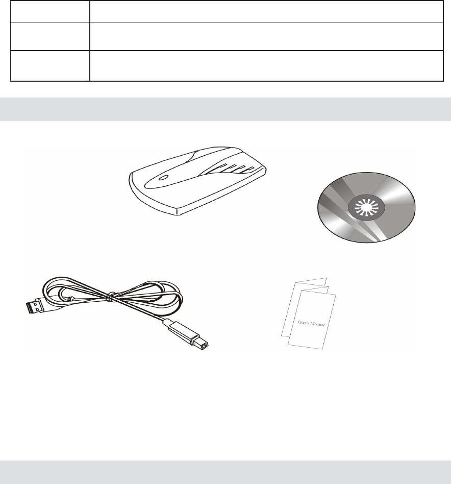
Package Contents
One 11Mbps Wireless LAN USB adapter.
One USB Cable.
One setup Utility CD-ROM( User Guide on CD).
Quick Installation Guide.
System Requirements
An available USB port.
USB 1.1(12 Mbps) and USB 2.0(480 Mbps) ports ready.
Operating System: Windows 98, ME, NT, 2000, or XP.
2M bytes free disk space for utility and driver installation.
4
LED Indicator:
The Wireless LAN USB adapter includes an LED indicator, a described in the following table.
Status Description
ON
Flashing
Power ON (Green light)
Adapter is receiving or transmitting data via a wireless connection (Red light)
Chapter 2: Network Configuration and
Planning
Network Topology
Wireless LAN Basic
5
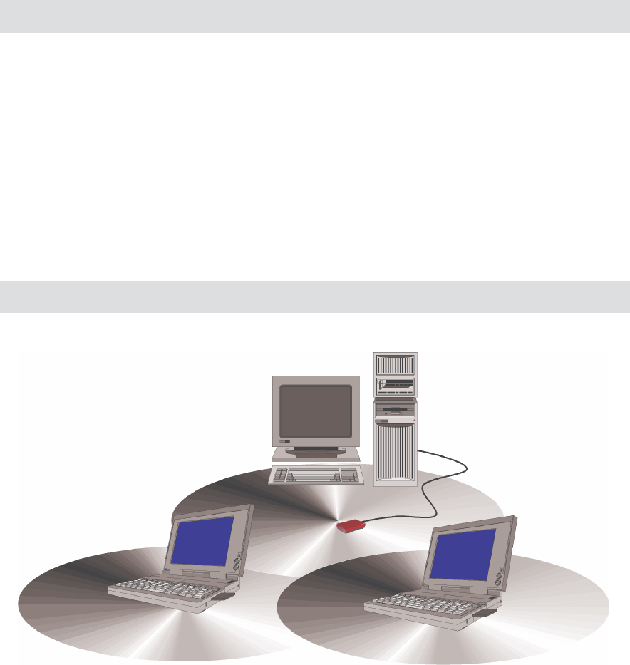
An Ad-Hoc wireless LAN is a group of computers, each equipped with one WLAN adapter,
connected as an independent wireless LAN. Computers in a specific Ad-Hoc wireless LAN must be
configured to share the same radio channel.
Fig 2-1 Ad-Hoc Wireless LAN
Notebook with PCMCIA WLAN Card
Notebook with PCMCIA WLAN Card
Desktop with USB WLAN Adapter
The adapter supports legacy Ethernet LAN network configuration options as defined by the
IEEE 802.11b standards committee.
The adapter can be configured as:
Ad-Hoc for departmental or SOHO LANs.
Infrastructure for enterprise LANs.
LAN-Interconnection for point-to-point link as campus backbone.
6
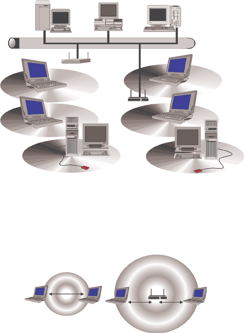
The adapter provides access to a wired LAN for wireless workstations. An integrated wireless
and wired LAN is called an infrastructure configuration. A group of adapter PC users and an Access
Point compose a Basic Service Set (BSS). Each adapter PC in a BSS can talk to any computer in
the wired LAN infrastructure via the Access Point.
An infrastructure configuration extends the accessibility of a adapter equipped PC to a wired
LAN, and doubles the effective wireless transmission range for 2 adapter PCs. Since the Access
Point is able to forward data within its BSS, the effective transmission range in an infrastructure LAN
is double.
The use of a unique ID in a BSS is essential. All adapter equipped PCs configured without
roaming options in independent BSS must be configured with a BSS ID corresponding to the Access
Point used in the BSS. Check your Access Point for its BSS ID or use the Access Point Browser
Utility program to determine the BSS ID
The infrastructure wireless LAN configuration is appropriate for enterprise-scale wireless
access to a central database, or as a wireless application for mobile users.
Fig 2-2 Infrastructure Wireless LAN
Notebook with PCMCIA WLAN Card
Desktop with USB WLAN Adapter
Access Point 1
Access Point 2
Server Desktop PC
Fig 2-3 The effective transmission range
Roaming
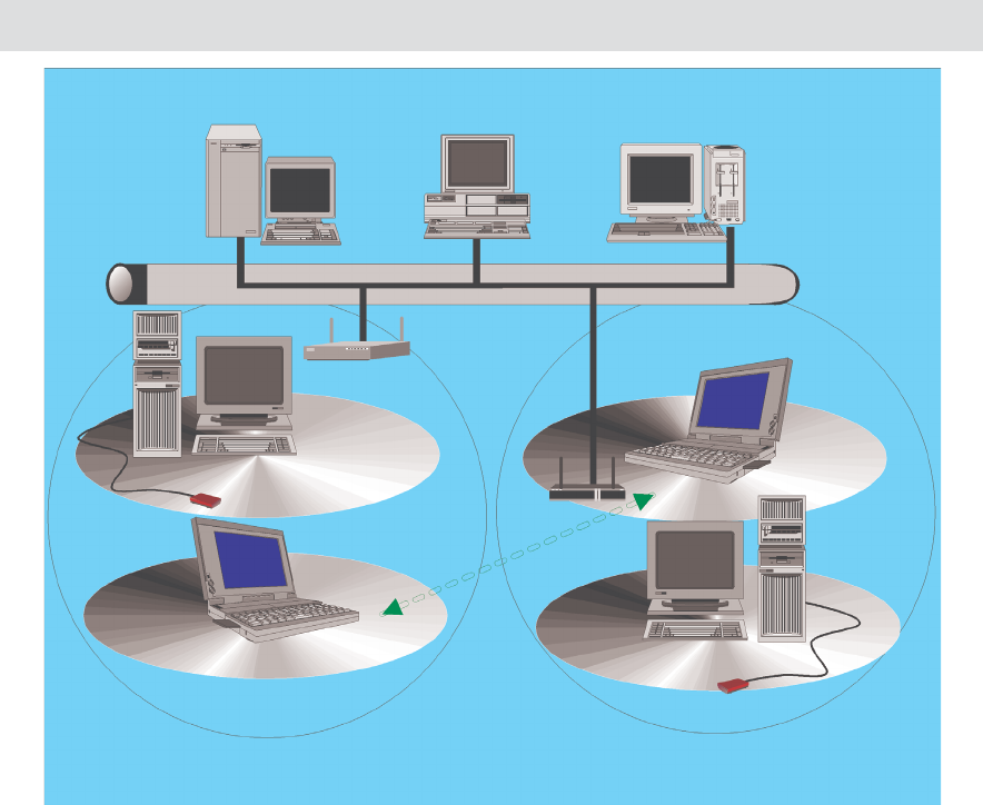
Infrastructure mode also supports roaming capabilities for mobile users. More than one BSS
can be configured as an Extended Service Set (ESS). The continuous network allows users to roam
freely within an ESS. All adapter PCs and Access Point within one ESS must be configured with the
same ESS ID.
Before enabling an ESS with roaming capability, it is recommended to select a feasible radio
channel and optimum Access Point position. Proper Access Point positioning combined with a clear
radio signal will greatly enhance performance.
Fig 2-4 Roaming in an Extended Service Set (ESS)
Access Point 1
Access Point 2
Notebook I
Notebook I
BSS1 BSS2
ESS
USB WLAN Adapter
USB WLAN Adapter
Server Desktop PC
7
Chapter 3: Installing the Drivers and Con-
figuration Utility for Windows 98, ME, NT,
2000
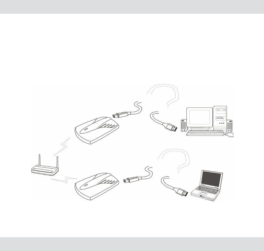
Inserting the adapter
To insert the wireless LAN USB adapter into a notebook or desktop computer, do the following:
1. Select an available USB port on the notebook or desktop PC.
2. Carefully insert the USB adapter cable’s Type-A plug (ie., the flat plug) into the USB port and
press until it is firmly seated in the port.
3. Insert the other end of the cable into the USB adapter.
Running the Auto Driver/Utility Installation
Fig 3-1 USB adapter installation
After properly inserting the Network Adapter into your notebook, will show find new hardware
the screen shown in Fig 3-2. Please select automatic search for a better driver click Next. The driver
will automatic install. When driver install completed. then install utility (Configuration Tools).
Before installing your card, insert the Setup Utility CD into your CD-ROM driver. Unless you
have deactivated the autorun feature of Windows, the screen shown in Fig 3-3 should appear
automatically.
8
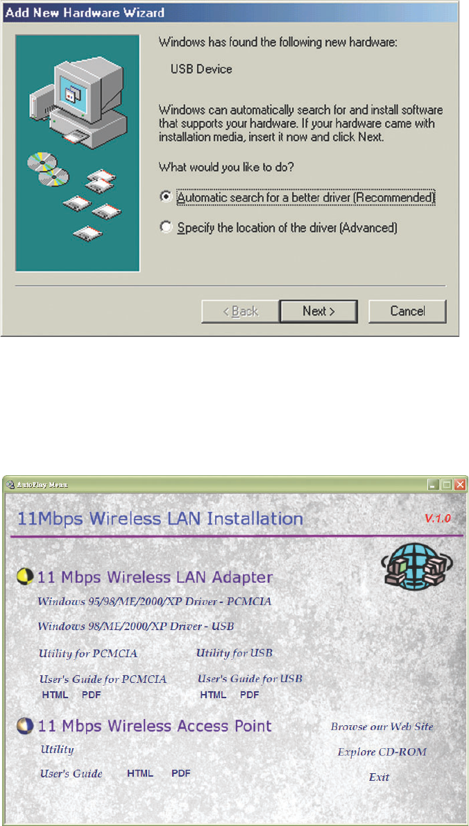
Fig 3-3 Autorun feature of Windows
9
If this screen doesn’t appear automatically, you can access the installation by clicking the Start
button and choosing Run. In the drop-down box provided type D:\Setup.exe (where D: is the letter
of your CD-ROM drive). Alternately, double-click My Computer and double-click the Setup.exe icon
in the folder that appears.
Fig 3-2 Add New Hardware
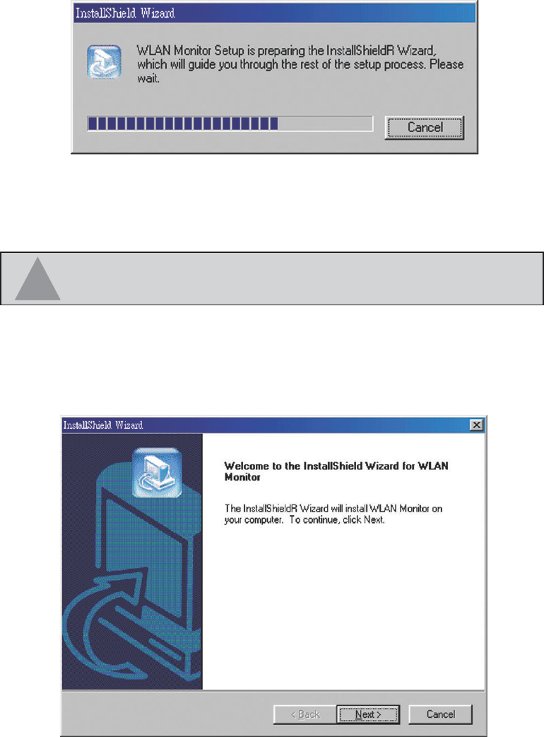
In Installation screen that you can select 11 Mbps Wireless LAN PC Card Utility, should now
be highlighted. Click the Utility button. A screen similar to that shown in Fig 3-4 should appear,
indicating that Windows is preparing the installation.
If, for whatever reason, you need to abort or terminate the installation, press the Cancel button
at any time during the installation. Otherwise the installation will continue automatically.
Fig 3-4 InstallShield running
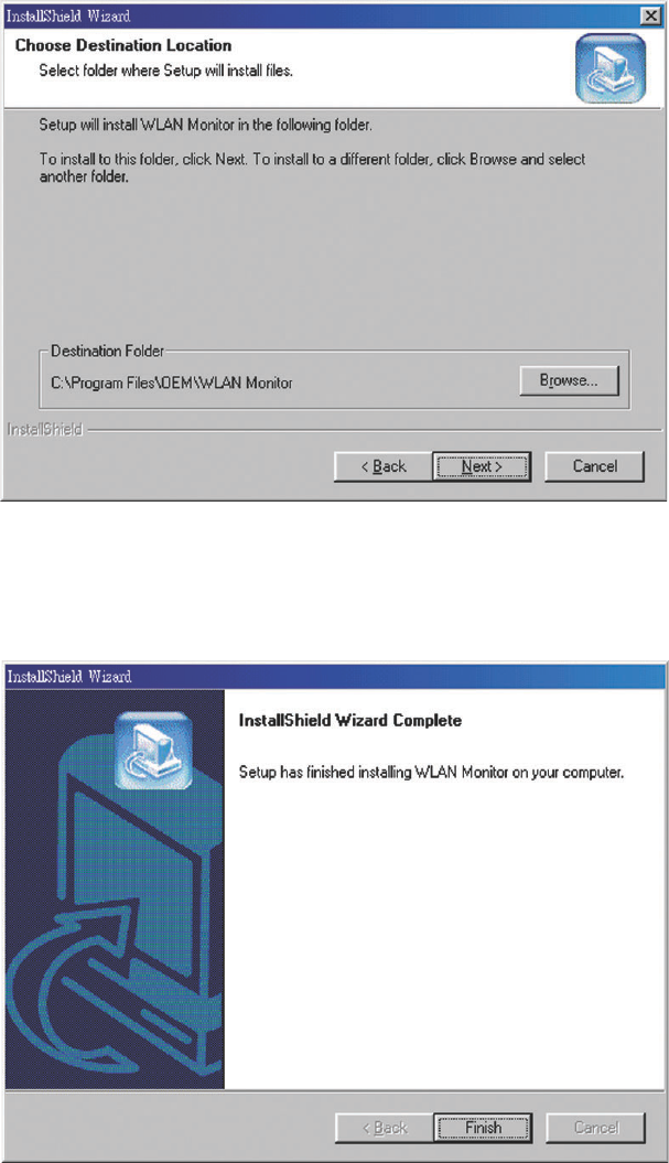
The screen in Fig 3-5 will appear next, indicating that Windows is ready to continue the installa-
tion. Click the NEXT button.
10
NOTE: If you stop the installation before it has finished, you will have
to run the complete installation again before installing your hardware.
33
33
3
Fig 3-5
The screen in Fig 3-6 will appear next, requesting the folder into which the Configuration Utility
will be installed. To install the configuration Utility in the default directory (recommended), click Next
button. If you prefer to install the Utility in another directory, click Browse button, and locate the
preferred directory. Then click the Next button.
Fig 3-6
After Windows has finished copying the necessary files, a screen similar to that shown in
Fig-3-7 will appear. Configuration Utility please see Chapter 4
Fig 3-7
11

Chapter 4: Configuration Utility
Using the configuration Utility
The Configuration Utility is provided to allow you further customization of the WLAN PC Card
and your wireless network.
After the Configuration Utility has been installed, an icon will placed in the system tray (next to
click button of your screen) when the WLAN PC Card is inserted, as shown in Fig 4-1.
Fig 4-1
The utility is divided into six parts: Status, Statistics, Site Survey, Encryption, Advanced,
and Info. You should change all your configuration settings for your WLAN PC Card using this utility
and not with the Network Properties section in your Control Panel.
12
Status
The Status screen (Shown in Fig 4-2) provides information about the current link between the
Network PC Card and Wireless Access Point.
When in Infrastructure Mode, Status will display the connection statistics for the network
segment that you are on.
The Channel field shows to what channel the WLAN PC Card is set.
The SSID field shows the current SSID set fir the wireless network. This SSID can be modified
at you click Change bottom.
The Tx Rate field shows the transfer rate in megabits per second.
The Int. Roaming field shows to use this feature to allow your adapter to retrieve country
information from the access point and behave according to that country’s regulations.
The Radio field shows on / off radio signal
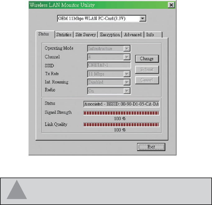
Fig 4-2
The Signal Strength field will display a bar indicating the percentage, between 0 and 100
percent, of the strength of the signal. The higher the percentage, the stronger the signal.
The Link Quality field will display a bar indicating the percentage, between 0 and 100 percent,
of the quality of the link. The higher the percentage, the better the link.
The Change bottom, allows you to customize the setting for the WLAN PC Card and your
wireless network.
The Operating Mode setting determines the architecture of your wireless network select Ad-
Hoc or Infrastructure Mode depending on your network type. The Ad-Hoc mode is used for sample
peer-to-peer network and allows the sharing of local resources only between Network PC Card
without needing a Wireless Access Point. The Infrastructure mode allows a wireless network to be
integrated into an existed, wired network through an Access Point. Infrastructure networks permit
roaming between Access Points while maintaining a connection to all network resources.
NOTE: When in Ad-Hoc mode, Signal Strength and Link
Quality indicators will not be available.
33
33
3
13
An acronym for Service Set Identifier, SSID is the unique name shared among all points in a
wireless network. The SSID must be identical for all points in the network. It is case sensitive and
must not exceed 32 characters.
The Tx Rate field shows the current transfer rate for the Network PC Card. To optimize perfor-
mance and range, the Tx Rate should be set to Auto, which will automatically adjust the transfer
speed for best performance and longest range.
The Channel setting specifies the channel used in wireless communication and should be set
to the same channel as the other points in the wireless network. The setting can only be adjusted in
Ad-Hoc mode.
Fig 4-3
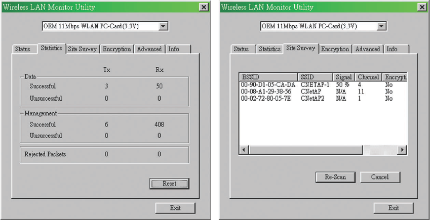
Statistics
The Statistics screen (Shown in Fig 4-3) provides information about the Tx / Rx Data, Manage-
ment, rejected Packets.
Site Survey
The Site Survey screen shows the available access point and their features. Click on the
desired access point. Then double click BSSID to connect or Re-Scan to search for more access
points. (Shown in Fig 4-4)
Fig 4-4
14