CNet Technology CUA854 Wireless-G Long Range USB Adapter with Antenna User Manual User s manual 20071030

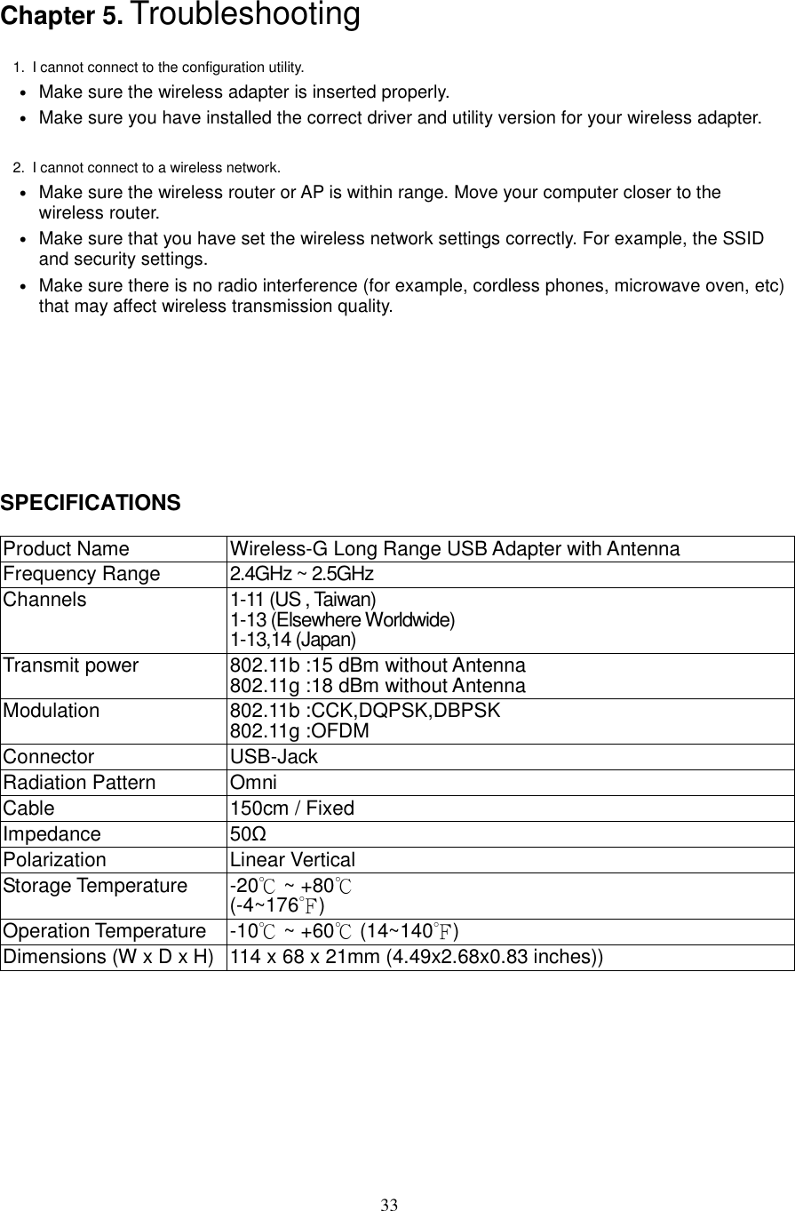
CNet Technology Inc Wireless-G Long Range USB Adapter with Antenna User s manual 20071030

Manual

     CUA-854/854L Wireless-G Long Range USB Adapter with Antenna   User’s Guide
 2  Table of Contents  Chapter 1. Introduction....................................................................................5 1.1. About CUA-854..................................................................................................5 1.2. Key Features......................................................................................................5 1.3. Package Included...............................................................................................5 Chapter 2. Connect your antenna...................................................................6 Chapter 3. Installing Driver, Configuration Utility and Hardware.................7 3.1. Driver Installation for Windows 98SE/ME/2000/2003/XP.....................................7 3.2. Driver Installation for Windows Vista.................................................................10 Chapter 4. Using the Configuration Utility for 98SE/ME/2000/2003/XP .....14 4.1. Overview..........................................................................................................14 4.2. Access the Configuration Utility ........................................................................14 4.3. Getting to Know the Utility ................................................................................16 4.3.1. Profile..............................................................................................................16 4.3.2. Link Status......................................................................................................27 4.3.3. Site Survey .....................................................................................................28 4.3.4. Statistics.........................................................................................................30 4.3.5. Advanced........................................................................................................31 4.3.6. About ..............................................................................................................32 Chapter 5. Troubleshooting ..........................................................................33
 3 List of Figures  Figure 2-1 connect antenna with SMA connector....................................................................6 Figure 3-1 AutoPlay Menu.........................................................................................................7 Figure 3-2 Setup: License Agreement ......................................................................................7 Figure 3-3 Setup: Choose Configuration ...................... 錯誤錯誤錯誤錯誤!  尚未定義書籤尚未定義書籤尚未定義書籤尚未定義書籤。。。。 Figure 3-4 Setup: Setup Status.................................................................................................8 Figure 3-5 Setup: plug-in message...........................................................................................8 Figure 3-6 Setup: Click Finish to Complete (for WIN2000 / 2003 / XP) ....................................8 Figure 3-7 Setup: Click Finish to Complete (for WIN98 / ME)..................................................9 Figure 3-8 AutoPlay Confirm Window (Vista).........................................................................10 Figure 3-9 AutoPlay Menu (Vista) ...........................................................................................10 Figure 3-10 Setup: License Agreement (Vista).......................................................................10 Figure 3-11 Setup: Setup Status (Vista).................................................................................. 11 Figure 3-12 Setup: plug-in message (Vista) ........................................................................... 11 Figure 3-13 Setup: Found New Hardware (Vista) ...................................................................12 Figure 3-14 Setup: Click Finish to Complete (Vista) ..............................................................12 Figure 4-1 Utility Icon..............................................................................................................14 Figure 4-2 Wireless Zero Configuration: Select Manage .......................................................14 Figure 4-3 Wireless Zero Configuration: Select Wireless Zero Configuration......................15 Figure 4-4 Wireless Zero Configuration: Select Disable........................................................15 Figure 4-5 Utility – Profile .......................................................................................................16 Figure 4-6 Add Profile: Configuration ....................................................................................18 Figure 4-7 Add Profile: Authentication and Security: Open or Shared Key..........................20 Figure 4-8 Add Profile: Authentication and Security: LEAP..................................................22 Figure 4-9 Add Profile: Authentication and Security: WPA/ WPA-PSK/ WPA2/ WPA-PSK ...23 Figure 4-10 Add Profile: Authentication and Security: 802.1x Setting: Certification ...........24 Figure 4-11 Add Profile: Authentication and Security: 802.1x Setting: CA Server ...............26 Figure 4-12 Utility - Link Status...............................................................................................27 Figure 4-13 Utility – Site Survey .............................................................................................28 Figure 4-14 Utility – Statistics.................................................................................................30 Figure 4-15 Utility – Advanced................................................................. 錯誤錯誤錯誤錯誤!  尚未定義書籤尚未定義書籤尚未定義書籤尚未定義書籤。。。。 Figure 4-16 Utility - Link About ...............................................................................................32
 4  List of Figures  Table 4-1 Profile.......................................................................................................................17 Table 4-2 Configuration...........................................................................................................19 Table 4-3 Authentication: Open or Shared .............................................................................21 Table 4-4 Authentication: LEAP..............................................................................................22 Table 4-5 Authentication: WPA/ WPA-PSK/ WPA2/ WPA-PSK................................................23 Table 4-6 Authentication: 802.1x Setting: Ceritication...........................................................25 Table 4-7 Authentication: 802.1x Setting: CA Server .............................................................26 Table 4-8 Link Status...............................................................................................................27 Table 4-9 Site Survey...............................................................................................................29 Table 4-10 Statistics ................................................................................................................30 Table 4-11 Advanced ...............................................................................................................31
 5 Chapter 1.  Introduction  1.1.   About CUA-854  Once installed and connected, you can keep in touch with friends and work through e-mail, instant messaging and chat rooms as well as sharing files and other network resources such as printers and network storage with other computers.    The CUA-854 follows IEEE 802.11g wireless standard works at the speed of 54Mbps and for added versatility; it also interoperates with all Wireless-B (IEEE 802.11b) products found at homes, businesses, and public wireless hotspots around the country.    1.2.   Key Features  The following lists the main features of the Wireless-G USB Adapter. • 5 Times Faster and seamless operation with existing Wireless-B networks. • 64/128-bit WEP and WPA/WPA2 (Wi-Fi Protected Access) Encryption Provides Maximum Wireless Security. • Compatible with Windows 98SE/ME/2000/2003/XP/Vista. • The CUA-854 is with a magnet base which can be stick.  1.3.   Package Included  • CUA-854 with 5 dBi or 7 dBi antenna   • CD with driver, utility and User’s Guide • The QIG
 6 Chapter 2. Connect your antenna      Figure 2-1 connect antenna with SMA connector
 7 Chapter 3. Installing Driver, Configuration Utility and Hardware 3.1.   Driver Installation for Windows 98SE/ME/2000/2003/XP  Before installing your long range Wireless-G USB Adapter, insert the Auto-Install CD into your CD-ROM drive. Unless you have disabled the auto-run feature of Windows, the AutoPlay Menu should appear automatically. If not, you can manually access the installation by clicking the Start button and choosing Run. In the drop-down box type D:\ AUTORUN.EXE (where D: is the drive letter for your CD-ROM drive).      Alternately, double-click My Computer and double-click on the CD drive icon.  -  Click on CUA-854 to install driver/utility for your Long Range Wireless-G USB Adapter. Figure 3-1 AutoPlay Menu    -  After reading through the License Agreement, please click Yes to continue. Figure 3-2 Setup: License Agreement      -      Choose the Optimize for performance mode and click Next, you will get
 8    -      The driver will be installed to your computer. The Setup Status screen will be displayed.  Figure 3-3 Setup: Setup Status        -  During the installation, there will pops up a plug-in message screen. Please insert the Wireless-G USB Adapter into the USB port at this moment.   Figure 3-4 Setup: plug-in message      -  In Windows XP and 2000, click Finish to complete the installation.  Figure 3-5 Setup: Click Finish to Complete (for WIN2000 / 2003 / XP)
 9        -  In Windows 98SE and ME, please select Yes, I want to restart my computer now and click Finish to complete the installation. The system will restart automatically.  Figure 3-6 Setup: Click Finish to Complete (for WIN98 / ME)      Note: In Windows ME and 98SE, after the installation is completed, Windows will ask to restart the computer, just click Yes to restart.
 10  3.2.   Driver Installation for Windows Vista  Before installing your Long Range Wireless-G USB Adapter, insert the Auto-Install CD into your CD-ROM drive.  -  There will be a Vista AutoPlay Confirm Window. Click Run AUTORUN.EXE icon.  Figure 3-7 AutoPlay Confirm Window (Vista)    -  Click on CUA-854 to install driver/utility for your Wireless-G USB Adapter.  Figure 3-8 AutoPlay Menu (Vista)    -  After reading through the License Agreement, please click Yes to continue.  Figure 3-9 Setup: License Agreement (Vista)
 11            -      The driver will be installed to your computer. The Setup Status screen will be displayed.  Figure 3-10 Setup: Setup Status (Vista)    -  There will be a plug-in message screen. Please insert the Wireless-G USB Adapter into the USB port now.    Figure 3-11 Setup: plug-in message (Vista)
 12                         -  Click Ask me again later when the Found New Hardware window appears. Figure 3-12 Setup: Found New Hardware (Vista)    -  Click Finish to complete the installation.  Figure 3-13 Setup: Click Finish to Complete (Vista)
 13
 14 Chapter 4. Using the Configuration Utility for 98SE/ME/2000/2003/XP  4.1.   Overview  The wireless Configuration Utility can be used to check link information, search for available wireless networks, or to create profiles that hold different configuration settings.  4.2.   Access the Configuration Utility  The Configuration Utility icon will appear in your system tray. Double-click the icon. Figure 4-1 Utility Icon     The utility contains six parts: Profile, Link Status, Site Survey, Statistics, Advance, and About. You should change all your configuration settings for the Wireless-G USB Adapter by using this utility.  Note: In Windows XP, you should disable the Wireless Zero Configuration service following the steps below:  A.  Right Click My Computer on the desktop and select Manage.  Figure 4-2 Wireless Zero Configuration: Select Manage
 15 B.  The Computer Management window comes up. Select Services from the Services and Applications menu. Scroll down to locate Wireless Zero Configuration service.  Figure 4-3 Wireless Zero Configuration: Select Wireless Zero Configuration    C.  Double Click on Wireless Zero Configuration to go into its properties. For Startup type, choose Disable to disable the Wireless Zero Configuration then click Apply and OK to make the changes effective. Now you can use our Configuration Utility instead of Windows XP Wireless Zero Configuration Utility.  Figure 4-4 Wireless Zero Configuration: Select Disable
 16 4.3.   Getting to Know the Utility  4.3.1.  Profile The Profile can keep your favorite wireless settings among your home, office and other public hotspots. You may save multiple profiles and activate the correct one at your preference.  Figure 4-5 Utility – Profile
 17 Table 4-1 Profile  LABE L DE S CR IP T IO N Profile Name  Connection profile name. There is a connection icon standing for the connection status,   : Indicate connection is successful on currently activated profile.   : Indicate connection fails on currently activated profile. SSID  Wireless station or ad-hoc name. Channel  Channel in use for this wireless connection. Authentication  The Authentication method used for this profile. Encryption  The Encryption type used for this profile. Network Type  The Network type used for this profile. Add  Click Add to create a new profile. Delete  Click Delete to delete a selected profile. Edit  Select a profile, and click Edit to change an existing profile. Activate  To activate a specific profile, select the profile, and click Activate button. OK  To pop-down this utility menu. Help  Click Help to display on-line help information in a pop-up screen.
 18 4.3.1.1.  Create a New Profile  Click the Add button on the Profile screen to create a new profile. (A) Add Profile: Configuration Fill the Profile Name and SSID for this new profile. Figure 4-6 Add Profile: Configuration
 19  Table 4-2 Configuration  LABE L DE S CR IP T IO N Profile Name  Enter the profile name that you want. SSID  User can key in the intended SSID name or use pull down menu to select from available wireless network. PSM  CAM (Constantly Awake Mode) – the wireless Adapter will stay full power when AC power cord is plugged into power outlet. PSM (Power Saving Mode) – the wireless Adapter will enter the power saving mode. Network Type  There are two wireless modes. (A) Infrastructure - This mode allows wireless and wired networks to communicate through an access point. (B) Ad-hoc - This mode allows wireless-equipped computers to communicate directly with each other. Preamble  There are three types: Auto, Long and Short are supported. Ad-hoc wireless mode  There are three types: 802.11B only, 802.11B/G mixed and 802.11G only modes are supported. TX Power  Transmit power, the amount of power used by a radio transceiver to send the signal out. User can choose power value by sliding the bar. RTS Threshold  User can adjust the RTS threshold number by sliding the bar or key in the value directly. The default value is 2347. Fragment Threshold  User can adjust the Fragment Threshold number by sliding the bar or key in the value directly. The default value is 2346. Channel  Only available for setting under ad-hoc mode. User can choose the channel frequency to start their ad-hoc network. OK  Confirms and saves the settings. Cancel  Ignore the settings and return to the previous screen. Help  Click Help to display on-line help information in a pop-up screen.
 20 (B) Add Profile: Authentication and Security Enter the authentication and security information here.   Figure 4-7 Add Profile: Authentication and Security: Open or Shared Key
 21 Table 4-3 Authentication: Open or Shared  LABE L DE S CR IP T IO N Authentication Type  Under Open System authentication, any wireless station can request authentication. Under Shared Key authentication, each wireless station is assumed to have received a secret shared key over a secure channel that is independent from the 802.11 wireless network communications channel. To use Shared Key authentication, you must have a network key. Encryption  Select None or WEP WEP Key#1 .. 4  When select the WEP encryption or Shared Key authentication without 802.1x, you should enter the WEP key correctly. If the WEP key is 64-bit, please enter 10 hexadecimal or 5 ASCII characters. If the WEP key is 128-bit, please enter 26 hexadecimal or 13 ASCII characters. Show Password  When you check this function, the password will not be covered by * symbol. Use 802.1x  Select this option to enable IEEE 802.1x for user authentication. IEEE 802.1x can support true authentication and user control 802.1x setting  When enabling IEEE 802.1x, you should set the IEEE 802.1x parameters.
 22 Figure 4-8 Add Profile: Authentication and Security: LEAP     Table 4-4 Authentication: LEAP  LABE L DE S CR IP T IO N Authentication Type  Light Extensible Authentication Protocol. It is an EAP authentication type used primarily in Cisco Aironet WLANs. It encrypts data transmissions using dynamically generated WEP keys, and supports mutual authentication. Identity  Enter identity for the LEAP authentication service Password  Enter password for the LEAP authentication service. Show Password  When you check this function, the password will not be covered by * symbol.
 23 Figure 4-9 Add Profile: Authentication and Security: WPA/ WPA-PSK/ WPA2/ WPA-PSK    Table 4-5 Authentication: WPA/ WPA-PSK/ WPA2/ WPA-PSK  LABE L DE S CR IP T IO N Authentication Type  Select WPA, WPA-PSK, WPA2 or WPA-PSK Encryption  Specify an encryption method to use. Select TKIP (Temporal Key Integrity Protocol) that uses a stronger encryption algorithm and protects against hackers with MIC (Message Integrity Check). Select AES (Advanced Encryption System) that uses symmetric 128-bit block data encryption. WPA-PSK  Enter WPA Preshared Key, only valid for WPA-PSK and WPA2-PSK. This key should be between 8 and 32 characters in length. 802.1x setting  Only valid for WPA and WPA2. Show Password  When you check this function, the password will not be covered by * symbol.
 24  (C) Add Profile: 802.1x IEEE 802.1x supports true authentication and user control.   Figure 4-10 Add Profile: Authentication and Security: 802.1x Setting: Certification
 25  Table 4-6 Authentication: 802.1x Setting: Ceritication  LABE L DE S CR IP T IO N Authentication Type  PEAP: Protected Extensible Authentication Protocol. PEAP transports authentication data by using tunneling between PEAP clients and an authentication server. PEAP can authenticate wireless LAN clients using only server-side certificates, thus simplifying the implementation and administration of a secure wireless LAN.  TLS////Smart Card: Transport Layer Security, provides with certificate-based and mutual authentication of the client and the network. It relies on client-side and server-side certificates to perform authentication and can be used to dynamically generate user-based and session-based WEP keys to secure subsequent communications between the WLAN client and the access point.  TTLS: Tunneled Transport Layer Security, this security method provides for certificate-based, mutual authentication of the client and network through an encrypted channel. Unlike EAP-TLS, EAP-TTLS requires only server-side certificates.      MD5-Challenge: Message Digest Challenge, is an EAP authentication type that provides base-level EAP support. It only supports one-way authentication i.e. there is no mutual authentication of wireless client and the network. It’s only valid for profile’s authentication type to be none or shared. Session Resumption  User can choose Disabled, Reauthenticate, Roaming, SameSsid or Always. Identity  Enter the Identity for server Password  Enter the Password for server Use Client Certificate Enable the client certificate for server authentication. Tunnel Authentication Protocol  Tunnel protocol, List information includes EAP-MSCHAP, EAP-MSCHAP v2, CAHAP and MD5. Identity  Enter Identity for tunnel Password  Enter Password for tunnel  If you want to use CA server, please click CA Server page. Depending on the EAP in use, only the server or both the server and client may be authenticated and require a certificate. Server certificates identify a server, usually an authentication or RADIUS server to clients. Most EAPs require a certificate issued by a root authority or a trusted commercial CA.
 26 Figure 4-11 Add Profile: Authentication and Security: 802.1x Setting: CA Server    Table 4-7 Authentication: 802.1x Setting: CA Server  LABE L DE S CR IP T IO N Use certificate chain  Enable the certificate feature Certificate issuer  Choose to use server that is the issuer of certificates. Allow intermidiate certificates It must be in the server certificate chain between the server   certificate and the server specified in the certificate issuer field. Server name  Enter the authentication server’s name. There are two matching methods, -  Server name must match exactly.   -  Domain name must end in specified name.
 27 4.3.2.   Link Status  The Link Status provides the link information of the Wireless-G USB Adapter with Atenna.  Figure 4-12 Utility - Link Status    Table 4-8 Link Status LABE L DE S CR IP T IO N Status  Displays current connection status. If no connection, it will show Disconnected. Otherwise, the SSID and BSSID will show here. Extra Info  Displays link status and current channel in use. Channel  Shows the channel which the wireless network devices are currently using. Link Speed  Tx(Mbps) field shows the transfer rate in megabits per second. Rx(Mbps) field shows the receive rate in megabits per second. Throughput  Shows the amount of data moved successfully form one place to another in a given time period. Link Quality  The level of Link Quality is displayed here by a bar indicating percentage, between 0 and 100 percent. Signal Strength  The level of Signal Strength is displayed here by a bar indicating percentage, between 0 and 100 percent. Noise Level  The Noise Level is displayed here by a bar indicating percentage, between 0 and 100 percent.
 28  4.3.3.   Site Survey  The site survey page displays a list of all Infrastructure and Ad-hoc wireless networks available for connection.  Figure 4-13 Utility – Site Survey
 29  Table 4-9 Site Survey  LABE L DE S CR IP T IO N SSID  Service Set ID of the Wireless Network. BSSID  Basic Service Set ID of the Wireless Network. Signal  Signal Strength status. Channel  The channel used by Wireless Network. Encryption  Encryption type. Authentication  Authentication type used. Network Type  Wireless Network mode. (Infrastructure mode or Ad-hoc mode) Rescan  Click Rescan to re-search for wireless networks. Connect  Select one of the networks on the list, and click the Connect button. Please note that if the wireless network has encryption enabled, you can’t connect. If you want to connect, you must add a profile in the Profile Tab. Note: There is no Connect button in Window Vista. You have to use the Add Profile feature to build the wireless connection with the selected network. Please refer to the Profile information. Add Profile  Add the selected network to Profile List.
 30  4.3.4.   Statistics  The Statistics screen provides information about the Transmit and Receive Statistics. You can reset counters if you need, otherwise click OK.  Figure 4-14 Utility – Statistics    Table 4-10 Statistics  LABE L DE S CR IP T IO N Transmit Statistics  Displays current transmit frame information  Receive Statistics  Displays current receive frame information. Reset Counter  Resets all counter to zero.
 31  4.3.5.   Advanced  The Advanced screen shows settings for Wireless Mode, Ad-hoc wireless mode,………            Table 4-11 Advanced  LABE L DE S CR IP T IO N Wireless mode  802.11 B only: allows to connect to the 802.11b wireless stations only. 802.11 B/G mix: allows to connect to the 802.11b or 802.11g wireless stations. Ad-hoc wireless mode When the network type is in Ad Hoc mode that the wireless adapter can only work in 802.11b data rate. It is defined by Wi-Fi organization. If you want to enable the data rate up to 54Mbps, please select Ad-hoc wireless mode. B/G Protection  If there are 802.11b and 802.11g wireless stations in the network, it is recommended to enable the B/G Protection mechanism. Auto: Based on the status of the network and automatically disable/enable protection mode. On: Always send frame with protection. Off: Always send frame without protection. Enable TCP Window Size Enables the TCP Window Size to improve the TCP performance over wireless link. Fast Roaming  Roaming mechanism setup by transmit power. Roaming will be happened if the station power is less than the defined power. Select Your Country Region Code Selects the correct region code for your country. CCX2.0  Supports Cisco Compatible Extensions functions: 1.  LEAP turn on CCKM 2.  Enable Radio Measurement: Channel measurement every 0~2000 milliseconds. Turn off RF/ Turn on RF You can turn off or turn on the RF feature. Apply  Save the changes.
 32  4.3.6.   About  The About screen shows release dates as well as driver/utility versions and the MAC/IP address of the wireless adapter.  Figure 4-15 Utility - Link About
 33 Chapter 5. Troubleshooting  1.  I cannot connect to the configuration utility.   • Make sure the wireless adapter is inserted properly.   • Make sure you have installed the correct driver and utility version for your wireless adapter.    2.  I cannot connect to a wireless network.   • Make sure the wireless router or AP is within range. Move your computer closer to the wireless router. • Make sure that you have set the wireless network settings correctly. For example, the SSID and security settings. • Make sure there is no radio interference (for example, cordless phones, microwave oven, etc) that may affect wireless transmission quality.        SPECIFICATIONS  Product Name  Wireless-G Long Range USB Adapter with Antenna Frequency Range  2.4GHz ~ 2.5GHz Channels  1-11 (US , Taiwan) 1-13 (Elsewhere Worldwide) 1-13,14 (Japan) Transmit power  802.11b :15 dBm without Antenna 802.11g :18 dBm without Antenna Modulation  802.11b :CCK,DQPSK,DBPSK 802.11g :OFDM Connector  USB-Jack Radiation Pattern  Omni Cable  150cm / Fixed Impedance  50Ω Polarization  Linear Vertical Storage Temperature  -20℃ ~ +80℃ (-4~176 )℉ Operation Temperature  -10℃ ~ +60℃ (14~140 )℉ Dimensions (W x D x H) 114 x 68 x 21mm (4.49x2.68x0.83 inches))
 34 5.1.     Europe – EU Declaration of Conformity  This device complies with the essential requirements of the R&TTE Directive 1999/5/EC. The following test methods have been applied in order to prove presumption of conformity with the essential requirements of the R&TTE Directive 1999/5/EC:  -  EN 60950-1: 2001 Safety of Information Technology Equipment  -  EN 50392: 2004 Generic standard to demonstrate the compliance of electronic and electrical apparatus with the basic restrictions related to human exposure to electromagnetic fields (0 Hz - 300 GHz)  -  EN 300 328 V1.6.1 (2004-11) Electromagnetic compatibility and Radio spectrum Matters (ERM); Wideband transmission systems; Data transmission equipment operating in the 2,4 GHz ISM band and using wide band modulation techniques; Harmonized EN covering essential requirements under article 3.2 of the R&TTE Directive  -  EN 301 489-17 V1.2.1 (2002-08) and EN 301 489-1 V1.5.1 (2004-11) Electromagnetic compatibility and Radio spectrum Matters (ERM); ElectroMagnetic Compatibility (EMC) standard for radio equipment and services; Part 17: Specific conditions for 2,4 GHz wideband transmission systems and 5 GHz high performance RLAN equipment  This device is a 2.4 GHz wideband transmission system (transceiver), intended for use in all EU member states and EFTA countries, except in France and Italy where restrictive use applies.  In Italy the end-user should apply for a license at the national spectrum authorities in order to obtain authorization to use the device for setting up outdoor radio links and/or for supplying public access to telecommunications and/or network services.  This device may not be used for setting up outdoor radio links in France and in some areas the RF output power may be limited to 10 mW EIRP in the frequency range of 2454 – 2483.5 MHz. For detailed information the end-user should contact the national spectrum authority in France.  CE0560
 35   Federal Communication Commission Interference Statement This equipment has been tested and found to comply with the limits for a Class  B  digital  device,  pursuant  to  Part  15  of  the  FCC  Rules.    These limits  are  designed  to  provide  reasonable  protection  against  harmful interference in a residential installation.    This equipment generates, uses and can radiate radio  frequency energy and, if not installed and  used in accordance with the instructions, may cause harmful interference to radio communications.    However,  there  is  no  guarantee  that  interference  will not occur in a particular installation.    If this equipment does cause harmful interference to radio or television reception, which can be determined by turning the equipment off and on, the user is encouraged to try to correct the interference by one of the following measures:  -  Reorient or relocate the receiving antenna. -  Increase the separation between the equipment and receiver. -  Connect the equipment into an outlet on a circuit different from that to which the receiver is connected. -  Consult the dealer or an experienced radio/TV technician for help.  This device complies with Part 15 of the FCC Rules. Operation is subject to  the  following  two  conditions:  (1)  This  device  may  not  cause  harmful interference,  and  (2)  this  device  must  accept  any interference  received, including interference that may cause undesired operation.  FCC Caution: Any changes or modifications not expressly approved by the party responsible for compliance could void the user's authority to operate this equipment.  IMPORTANT NOTE: FCC Radiation Exposure Statement:  This equipment complies with FCC radiation exposure limits set forth for an uncontrolled environment. This equipment should be installed and operated with minimum distance 20cm between the radiator & your body.  This transmitter must not be co-located or operating in conjunction with any other antenna or transmitter.

Navigation menu