CNet Technology CWR854 Wireless-G Router User Manual
CNet Technology Inc Wireless-G Router Users Manual
Contents
- 1. DoC
- 2. Users Manual
Users Manual
1
Wireless-G Router
User’s Guide
2
Table of Contents
Chapter 1: Introduction
Installing Your Router
System Requirements
Installation Instructions
Chapter 2: Preparing Your Network
Preparing Your Network
Configuring Windows for IP Networking
Collect ISP Information
Chapter 3: Configuring the Router’s Basic Functions
Basic Functions
Setup
Global Address
Wireless
Tools
Status
DHCP
Log
Statistic
Chapter 4: Configuring the Router’s Advanced Functions
Advanced Functions
Virtual Server
Filters
IP/URL Block
Special Apps
DMZ Host
MAC Clone
Dynamic DNS
Proxy DNS
3
Chapter 1: Introduction
˙Installing Your Router
In this chapter, you’ll learn how to connect your router.
˙System Requirements
˙One or more PCs (desktop or notebook) with Ethernet interface
˙Broadband Internet access
˙Ethernet cables
˙Wireless interface (if planning to use wireless functions)
˙Installation Instructions
Connecting the Router:
1. Make sure all systems are turned off, including the router, PC(s), and the cable or
DSL modem (if applicable).
2. Connect the WAN port on the router to your cable/DSL modem, Ethernet Server, or
hub.
3. Connect one or more client PCs to the LAN port(s).
4. Connect the power adapter (5VDC, 2A) to the power jack on the router. Then, plug
the power cable into an outlet.
5. Turn on your PC(s).
4
Chapter 2: Preparing Your Network
˙Preparing Your Network
In this chapter, you’ll learn what to do before configuring your router.
Before you can configure your router, you need to set up all the computers on your network for
TCP/IP networking. You also need to know certain information from your ISP.
˙Configuring Windows for IP Networking
You need to configure each computer in your network for TCP/IP networking. If you plan to use
the DHCP feature (recommended), you should configure each computer to receive an IP
address automatically. See the procedure below for instructions.
If you don’t plan to use DHCP, you’ll need to manually assign an IP address to each computer.
Refer to your Windows documentation for instructions on how to do this.
To configure Windows to receive dynamic IP address:
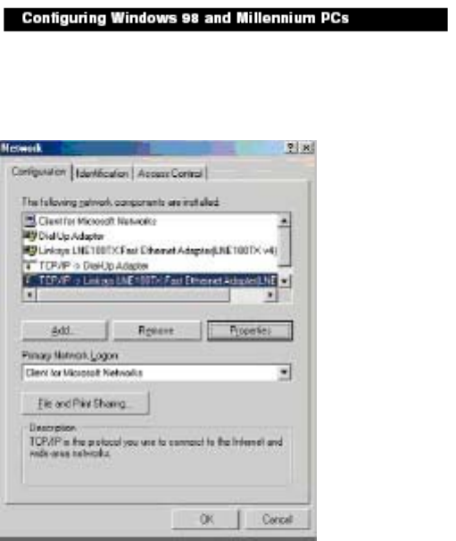
1. Click the Start button. Select Settings and click the Control Panel icon. Double-click the
Network icon.
2. On the Configuration tab, select the TCP/IP line for the applicable Ethernet adapter. Do not
choose a TCP/IP entry whose name mentions DUN, PPPoE, VPN, or AOL. If the word TCP/IP
appears by itself, select that line. Click the Properties button.
5
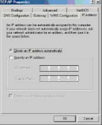
3. Click the IP Address tab. Select Obtain an IP address automatically
4. Now click the Gateway tab, and verify that the Installed Gateway field is
blank. Click the OK button.
5. Click the OK button again. Windows may ask you for the original Windows installation disk or
additional files. Check for the files at c:\windows\options\cabs, or insert your Windows CD-ROM
into your CDROM drive and check the correct file location, e.g., D:\win98, D:\win9x, etc. (if “D” is
the letter of your CD-ROM drive).
6. Windows may ask you to restart your PC. Click the Yes button. If Windows does not ask you to
restart, restart your computer anyway.
6
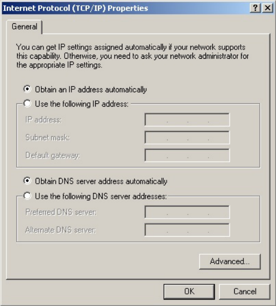
1. Click the Start button. Select Settings and click the Control Panel icon. Double-click the
Network and Dial-up Connections icon.
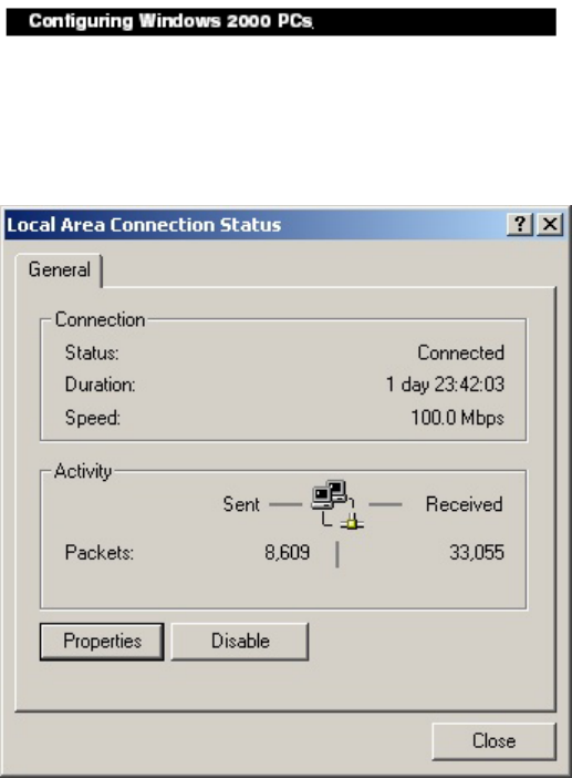
2. Select the Local Area Connection icon for the applicable Ethernet adapter (usually it is the first
Local Area Connection listed). Double-click the Local Area Connection. Click the Properties
button
7
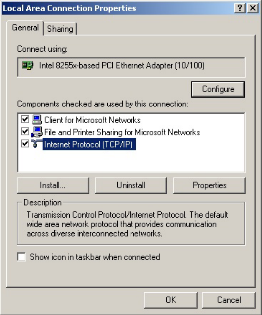
3. Make sure the box next to Internet Protocol (TCP/IP) is checked. Highlight Internet Protocol (TCP/IP),
and click the Properties button.
4. Select Obtain an IP address automatically. Once the new window appears, click the OK button.
Click the OK button again to complete the PC configuration.
8
5. Restart your computer.
9
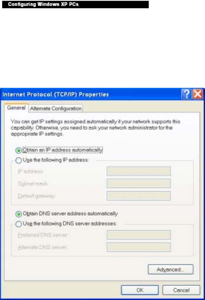
The following instructions assume you are running Windows XP with the default interface. If you
are using the Classic interface (where the icons and menus look like previous Windows versions),
please follow the instructions for Windows 2000.
1. Click the Start button and then the Control Panel icon. Click the Network and Internet
Connections icon. Then click the Network Connections icon.
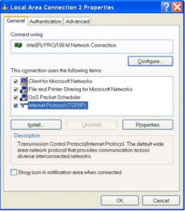
2. Select the Local Area Connection icon for the applicable Ethernet adapter (usually it is the first
Local Area Connection listed). Double-click the Local Area Connection. Click the Properties
button.
10
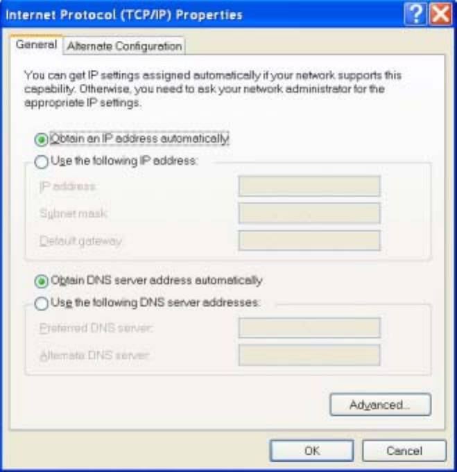
3. Make sure the box next to Internet Protocol (TCP/IP) is checked. Highlight Internet Protocol (TCP/IP),
and click the Properties button.
4. Select Obtain an IP address automatically. Once the new window appears, click the OK button. Click
the OK button again to complete the PC configuration.
11
˙Collecting ISP Information
The following information needs to be gathered from the ISP before you can configure
your router:
˙Has your ISP assigned you a static IP address, or will they assign one to you dynamically?
If they have given you a static IP, what is it?
˙Does your ISP use PPPoE? If so, what is your PPPoE username and password?
Call your ISP if you’re not sure of the answers to these questions.
12
Chapter 3: Configuring the Router’s Basic Functions
˙Basic Functions
Basic administrative functions include Setup, Global Address, Wireless, Tools, Status, DHCP,
Log, and Statistics.
The Wireless-G Router comes with a web-based tool that you can use to set up and customize
the router settings. You can access this tool from any computer on your network.
To open the web-based Admin Tool:
1. Open a browser on your PC.
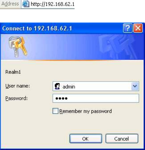
2. Type http://192.168.62.1 in the Address field:
A logon dialog box will appear:
3. Type admin in the User Name field. Then, type a Password and click OK. The default
password is 1234.
The Wireless-G Router Admin Tool will appear
13
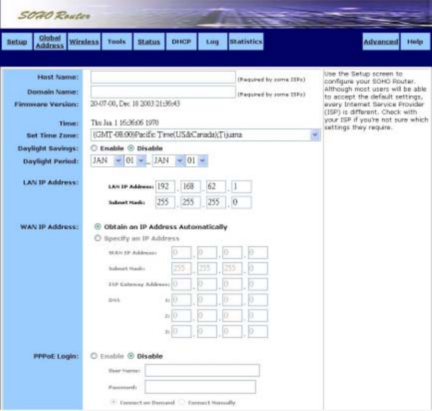
˙Setup
The Setup screen shows the basic configuration parameters for your router, such as Host
Name, LAN IP Address, and PPPoE Login.
Although most users will be able to accept the default settings, every Internet Service Provider
(ISP) is different. Check with your ISP if you're not sure which settings they require.
The Setup screen is shown in the figure below.
To configure Setup parameters:
1. Type the Host Name (optional). This value is sometimes called System Name or Account Name.
Check with your ISP if you’re not sure whether to provide this information.
2. Type the Domain Name of your ISP, such as xyz.isp.com (optional). Check with your ISP if
you’re not sure whether to provide this information.
3. Review the Firmware Version. This value tells you the version number and date of the firmware
you are currently using.
14
4. Select your Time Zone.
5 .Enable or disable Daylight Savings.
6. Review the LAN IP Address information and change it if necessary. These fields show the
Device IP Address and Subnet Mask as seen by others on your Local Area Network (LAN).
Most users will not need to change these values.
If your ISP uses PPPoE, choose Enable and go on to Step 8; otherwise, choose Disable and skip
to Step 7.
7. For WAN IP Address (also called the Public IP), choose either Obtain an IP Address
Automatically (most users) or Specify an IP Address (if your ISP assigns static IPs). If you
choose the second option, type in the Wide Area Network (WAN) IP Address, Subnet Mask,
ISP Gateway Address, and DNS information. Your ISP should provide these values.
8. Select your Point-to-Point Protocol over Ethernet (PPPoE) settings. PPPoE allows your ISP to
authenticate your connection by requiring you to submit a username and password.
9. Type in the PPPoE User Name and Password provided by your ISP.
10. Click Apply when you finish choosing your settings, or click Cancel to undo your changes.
15
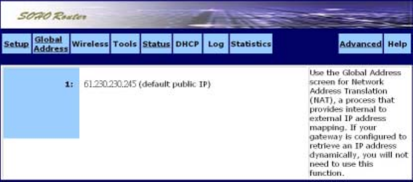
˙Global Address
Use the Global Address screen to set up Network Address Translation (NAT), a process that
provides internal to external IP address mapping. If your router is configured to retrieve an IP
address dynamically, you will not need to use this function.
The Global Address screen is shown in the figure below.
16
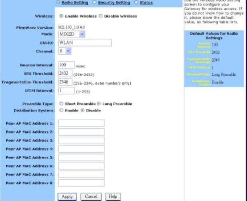
˙Wireless
Use the Wireless screen to configure your router for wireless access. Most users will only need
to look at the Basic settings, which include Wireless Enable/Disable, ESSID, Channel, and
WEP options. Some users may choose to configure the Advanced wireless settings, such as
Beacon Interval, Authentication Type, and Enhanced Security options. The Wireless screen is
shown in the figure below
Radio Setting:
To configure the Basic wireless options:
1. First, choose to Enable or Disable wireless access. None of the router’s wireless functions will
work unless you choose Enable.
2. Review the Firmware Version. This value tells you the version number of the wireless firmware
you are currently using.
3. Select Wireless Mode: If you have Wireless-G and Wireless-B devices in your network, then
keep the default setting, MIXED. If you have only Wireless-G devices, select G_ONLY. If you
have only Wireless-B devices, select B_ONLY.
4. Type in the Extended Service Set Identifier (ESSID)
17
5. Select the Channel number
Advanced Wireless Options
Most users will not need to configure the advanced wireless options.
To configure the Advanced wireless options:
1. Type a Beacon Interval. This value represents the time interval between beacons broadcast by
the Access Point (AP).
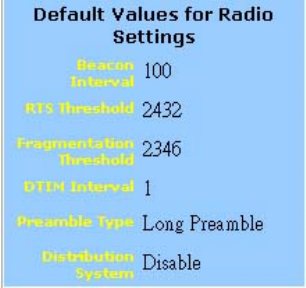
Note that the default values for the advanced wireless settings are shown in a table on the
right-hand side of the screen:
2. Type a value for RTS Threshold. This value represents the minimum size of data frames above
which Request-To-Send (RTS) protocol is used. RTS helps prevent data collision from hidden
nodes.
3. Type a value for Fragmentation Threshold. For efficiency in high-traffic situations, large files
are split into fragments. This parameter specifies the default packet size.
4. Type a value for DTIM Interval. This parameter specifies the number of beacon intervals
between successive Delivery Traffic Indication Maps (DTIMs).
5. Choose a Preamble Type, either Short (72 bits) or Long (144 bits).
6. Click Apply to put your changes in effect, or click Cancel to undo your changes.

18
Distribution System
This is WDS Function. WDS can extended your Wireless scope.
1. Select Enable
2. Fill the MAC Address of another Access Point which has WDS function. For example another
Access Point’s MAC Address is 00:08:A1:02:25:A2. In the Peer AP MAC Address 1, you must
fill 00:08:A1:02:25:A2
19
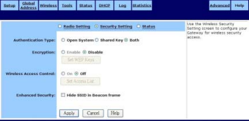
Security Setting:
Authentication Type: The default is set to Both, which allows either Open System or Shared Key
authentication to be used. For Open System authentication, the sender and
the recipient do NOT use a WEP key for authentication. For Shared Key
authentication, the sender and recipient use a WEP key for authentication.
If you want to use only Shared Key authentication, then select Shared Key.
20
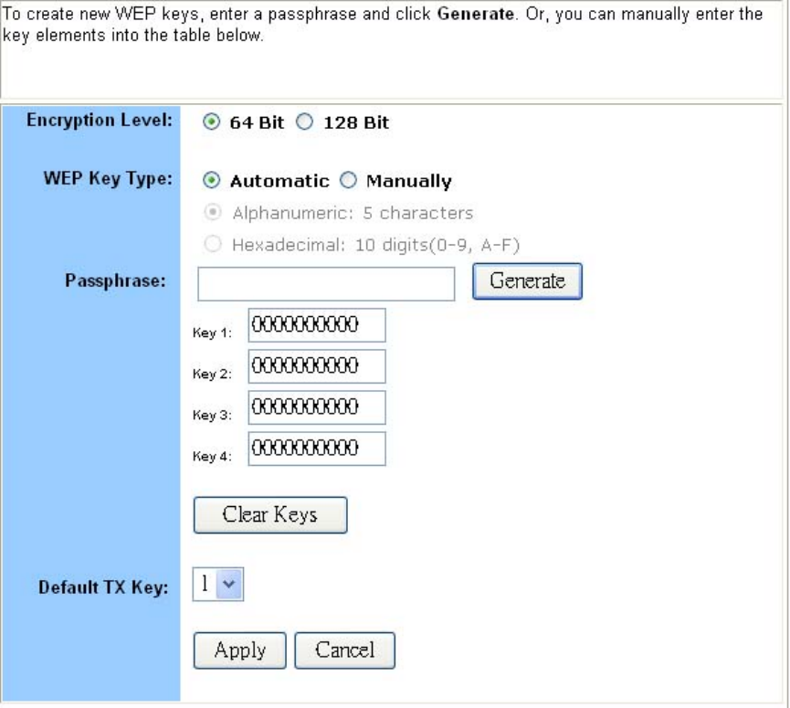
To set WEP keys:
1. To enable Wireless encryption function (recommended), select the Enable button and click “Set
WEP Keys” button. The Set WEP Keys window is shown in the figure below.
2. In the Set WEP Keys window, select the Encryption Level (64 Bit or 128 Bit).
Note: Although 128 Bit encryption uses a more secure encryption algorithm, it can slow
down your network’s data transmission rates.
3. Specify WEP keys by entering a Passphrase and clicking Generate, or by manually typing up
to four keys. Use the Clear Keys button to delete any unwanted key information.
4. Select the Default TX Key from the drop-down list. This value will determine the default
encryption key to be used.
5. Click Apply to put your changes in effect, or click Cancel to undo your changes.
6. Close the window when you are finished.
21
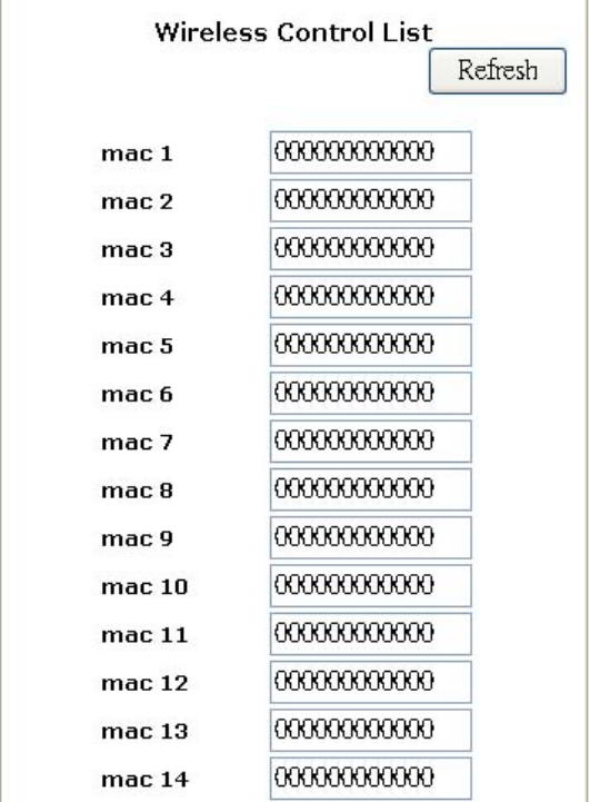
Wireless Access Control
Use the Wireless Control List window to allow access to the Internet based on users’ Media
Access Control (MAC) address.
To set wireless access controls:
1. Click On.
2. Click the Set Access List button on the Filters screen to launch the Wireless Control List
window:
3. Type the MAC address(es) that you want to allow into the table. You can allow access to up to
80 addresses.
4. Click Refresh to automatically update the values in the table.
5. To save your changes, click Submit at the bottom of the Wireless Control list; then close the
window.
Enhanced Security: When wireless clients survey the local area for wireless networks to
associate with, they will detect the SSID broadcast by the Router. To
broadcast the Router's SSID, keep the default setting. If you do not want to
broadcast the Router's ESSID, then select Hide SSID in Beacon frame.
22
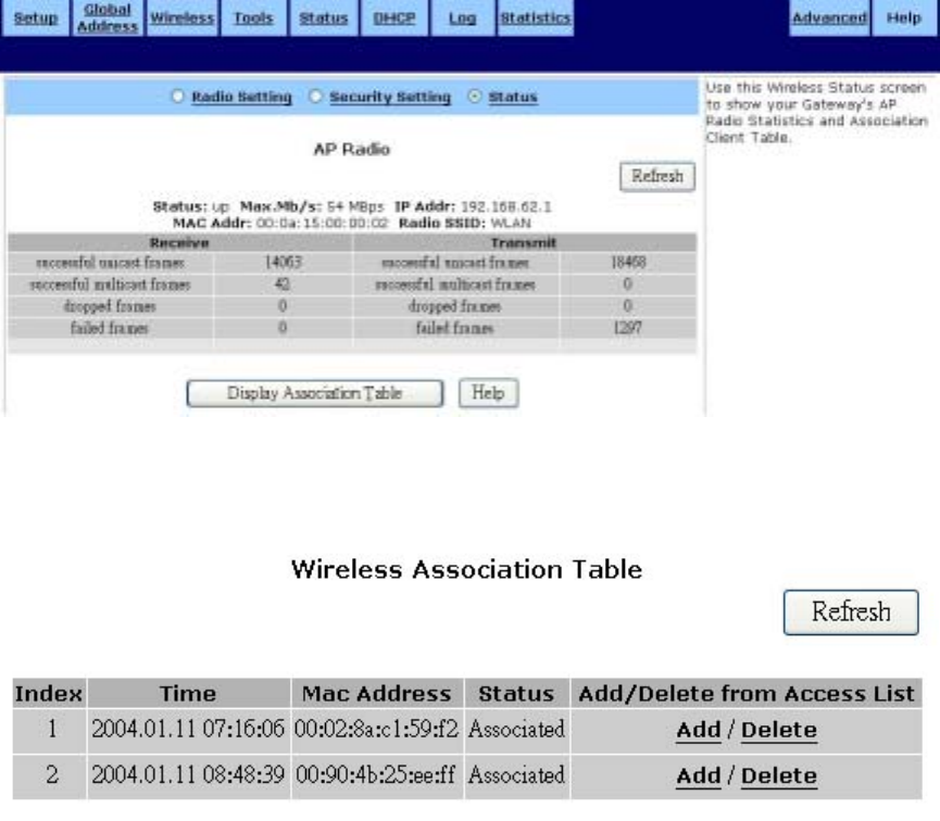
Status:
This table lists detailed statistics about the access point's radio, including Status, Max.MB/s, IP
Address, MAC Address, Radio SSID, Receive data, and Transmit data. Click Refresh to
automatically update the values in the table
To display the Wireless association table
1. Click Display Association Table to launch the Wireless Association Table:
2. Click Refresh to automatically update the values in the table.
3. Click Add to add a new device to the wireless access control list. The address is added to the
Wireless Control List table.
4. Click Delete to remove a device from the wireless access control list. The address is deleted
from the Wireless Control List table.
5. Click Refresh to automatically update the values in the table
23
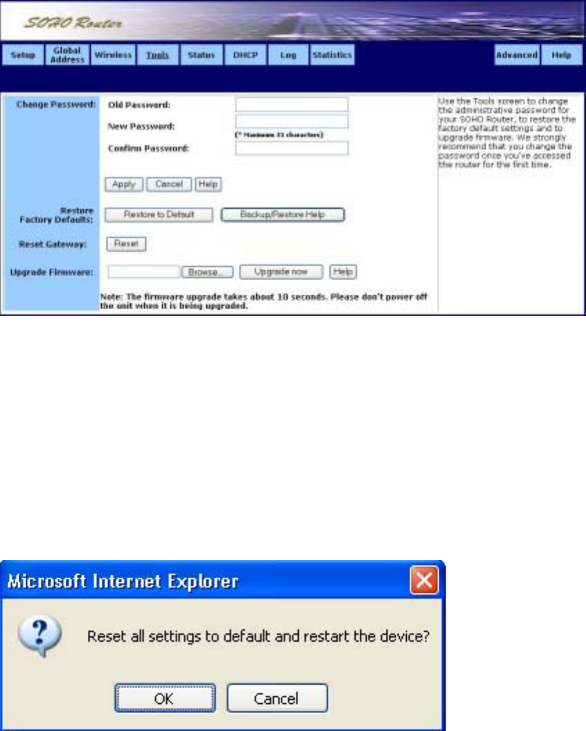
˙Tool
We strongly recommend that you change the password once you’ve accessed the router for the
first time. The Tools screen is shown in the figure below.
To change the administrative password:
1. Type in the Old Password. The factory default password is 1234.
2. Enter a New Password. The password you choose must be less than 64 characters.
3. Confirm your password in the Confirm Password field.
4. Click Apply to put your changes in effect, or click Cancel to undo your changes.
To restore the factory default settings:
1. Click Restore to Default. A warning dialog box appears:
2. Click OK. All your router’s settings will be restored to their factory default values.
24
To reset the Router:
1. Click Reset. A warning dialog box appears:
2. Click OK. Your router will Reset immediate.
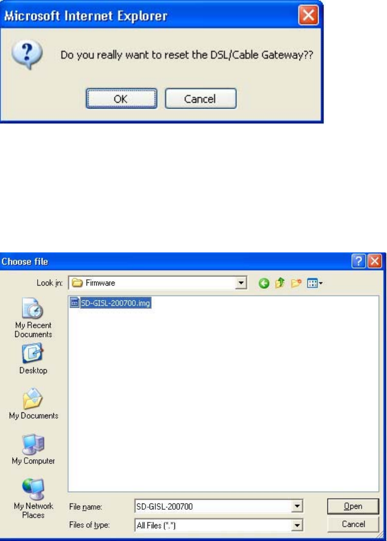
To upgrade the router’s firmware:
1. Download a firmware image file from the router website and save it to your hard drive. Make
sure to write down the file location.
2. Type the filename and path location directly into the Upgrade Firmware field, or click Browse…
to launch the Choose file dialog box:
Locate the firmware you downloaded and click Open.
3. Click Upgrade Now. The firmware of the device will be upgraded.
25
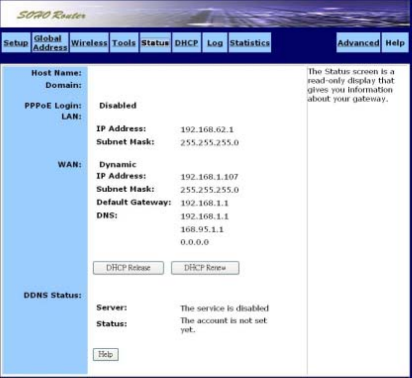
˙Status
The Status screen is a read-only display that gives you information about your router. The data
displayed may change depending on your current configuration. The Status screen is shown in the
figure below.
The displayed data may include:
Host Name
Domain
PPPoE Login (Enabled or Disabled)
LAN settings (IP Address and Subnet Mask)
WAN settings (IP Address, Subnet Mask, Default Gateway, and DNS information)
DDNS (Dynamic DNS) status (Server and Status)
To change any of these settings, go to the Setup screen.
DHCP Release and DHCP Renew
26
If you chose the Dynamic IP and PPPoE Disable options in the Setup screen, you’ll see the DHCP
Release and DHCP Renew buttons below the status information. Use these buttons to release or
renew the WAN IP address.
To release the WAN IP address:
Click DHCP Release.
To renew the WAN IP address:
Click DHCP Renew.
27
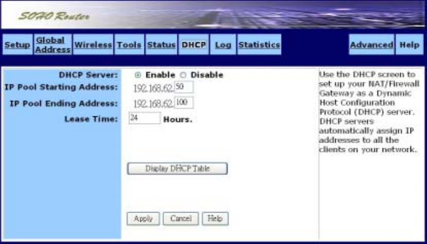
˙DHCP
Use the DHCP screen to set up your router as a Dynamic Host Configuration Protocol (DHCP)
server. DHCP servers automatically assign IP addresses to all the clients on your network.
The DHCP screen is shown in the figure below.
To set up your router as a DHCP server:
1. Make sure there is not already a DHCP server running on your network.
2. Make sure that each computer on your network is configured to receive an IP address
automatically.
3. On the DHCP screen, click Enable.
4. Type the IP Pool Starting Address. The address you specify will be the first IP address that can
be assigned to a computer on the network. Type the IP Pool Ending Address. The address you
specify will be the last IP address that can be assigned.
5. Click Apply to put your changes in effect, or click Cancel to undo your changes.
Display DHCP Table
Click Display DHCP Table to launch the DHCP Active IP window. In this screen, the DHCP Active
IP Table lists information about the computers that have been assigned IP addresses by the DHCP
server. For each active client, the table shows:
˙Index number
˙Client Hostname
˙IP Address
˙Mac Address
In addition, the DHCP Server IP Address is listed above the table.
You can click Refresh to see the latest data. Close the window when you are finished looking at
the table. The DHCP Active IP window is shown in the figure below.

28
29
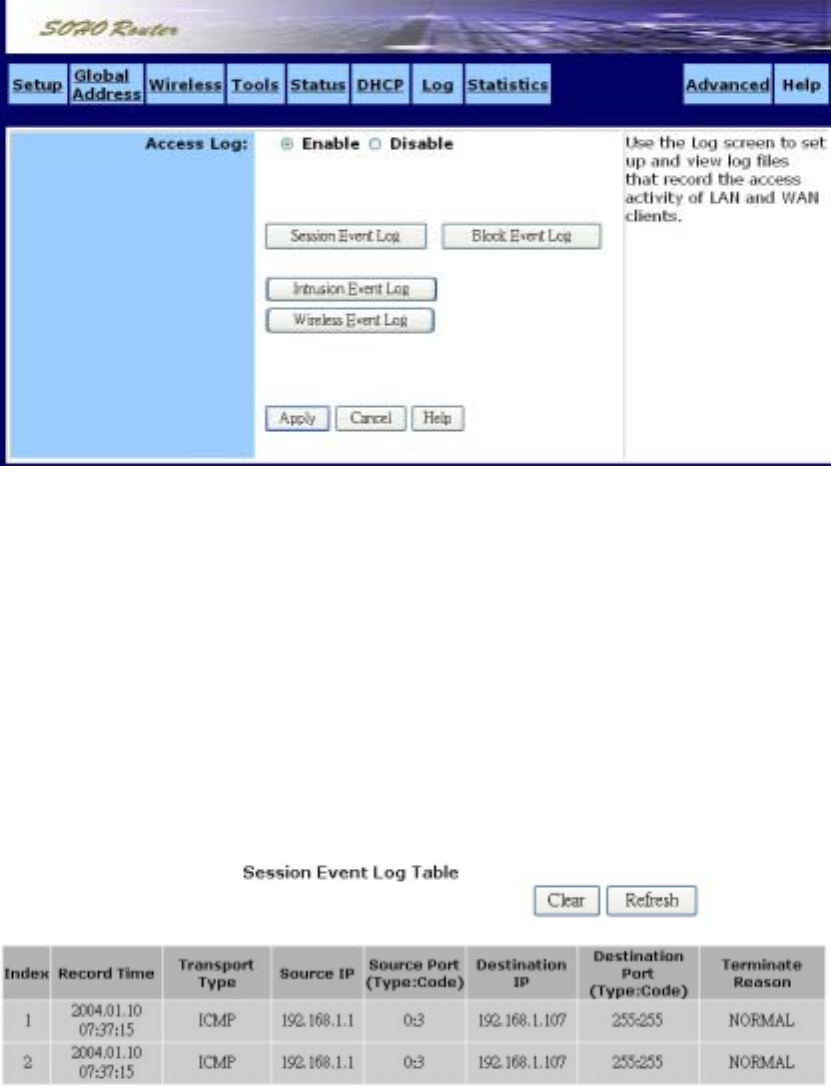
˙Log
Use the Log screen to set up and view log files that record the access activity of LAN and WAN clients.
The Log screen is shown in the figure below.
To set up logging on your router:
1. Click Enable for Access Log on the Log screen.
2. Click Apply to put your changes in effect, or click Cancel to undo your changes.
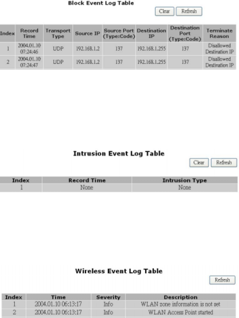
Session Event Log
Click Session Event Log to launch the Session Event Log window. In this screen, the Session
Event Log Table lists session event entries. The table shows the Index number, Transport Type,
Source IP, Source Port, Destination IP, Destination Port, and Terminate Reason for each event.
You can click Refresh to see the latest data. Make sure to close the window when you are finished
looking at the log.
The Session Event Log is shown in the figure below.
Block Event Log
Click Block Event Log to launch the Block Event Log window. In this screen, the Block Event Log
Table lists blocking event entries. The table shows the Index number, Transport Type, Source IP,
30
Source Port, Destination IP, Destination Port, and Terminate Reason for each event.
You can click Refresh to see the latest data. Make sure to close the window when you are finished
looking at the log.
The Block Event Log is shown in the figure below.
Intrusion Event Log
Click Intrusion Event Log to launch the Intrusion Event Log window. In this screen, the Intrusion
Event Log Table lists intrusion event entries. The table shows the Index number, Record Time, and
Intrusion Type for each intrusion event.
You can click Refresh to see the latest data. Make sure to close the window when you are finished
looking at the log.
The Intrusion Event Log is shown in the figure below.
Wireless Event Log
Click Wireless Event Log to launch the Wireless Event Log window. In this screen, the Wireless
Event Log table lists wireless event entries. The table shows the Index number, Time, Severity,
and Description for each event.
You can click Refresh to see the latest data. Make sure to close the window when you are finished
looking at the log.
The Wireless Event Log is shown in the figure below.
31
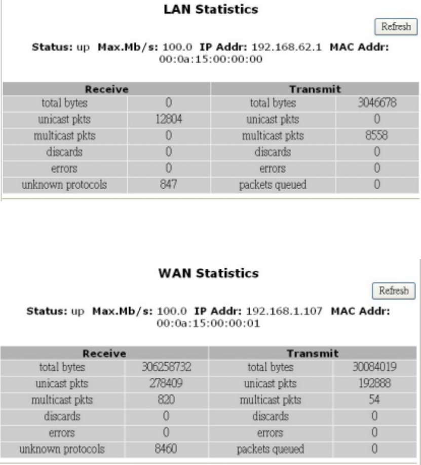
˙Statistics
Use the Statistics screen to view statistics for the LAN, WAN, and AP Radio ports.
LAN Statistics
This table lists detailed statistics on the LAN port.
WAN Statistics
This table lists detailed statistics on the WAN port.
AP Radio
This table lists detailed statistics on the access point's radio.
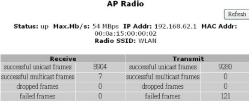
32
33
Chapter 4: Configure the Router’s Advanced Function
˙Advanced Functions
Advanced administrative functions include Virtual Servers, Filters, IP/URL Block, Special Apps,
DMZ Host, and MAC Clone, Proxy DNS.
The web-based Admin Tool allows you to set up advanced services and perform special functions,
such as filtering or cloning your MAC address. Most users will not need to use these features.
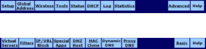
To toggle between Basic and Advanced Functions:
1. From the Basic functions screen set, click Advanced on the far right side of the menu bar to
access the Advanced screens:
2. Once you are in the Advanced screen set, click Basic on the far right side of the menu bar to
return to the Basic screens:
34
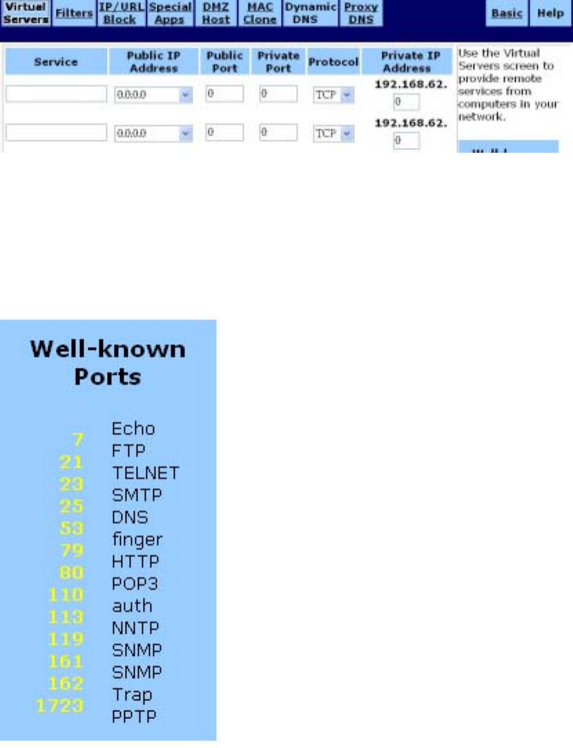
˙Virtual Server
Use the Virtual Servers screen to provide remote services, such as FTP or Telnet, from computers
in your network. The Virtual Servers screen is shown in the figure below.
To set up a computer on your network as a Virtual Server:
1. Enter the name you wish to give each application in Service field..
2. Select a Public IP Address from the drop-down list.
3. Specify a Service Port. For help on which port to choose, refer to the Well-known Ports table on
the right-hand side of the screen:
4. Select a Protocol (TCP, UDP, or Both) from the drop-down list.
35
5. Specify the Private IP Address. You only need to type the last part of the address; the first part
is set automatically.
6. Click Apply to put your changes in effect, or click Cancel to undo your changes.
To delete Virtual Servers:
For any Virtual Server you want to delete, select 0.0.0.0 for Public IP Address and click Apply.
36
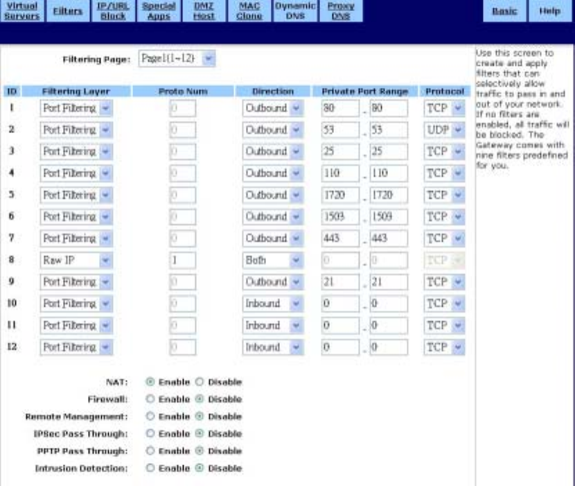
˙Filters
Use the Filters screen to create and apply filters that can selectively allow traffic to pass in and out
of your network. Your router comes with several filters predefined for you. The Filters screen is
shown in the figure below.
To set up a filter:
1. Select the Filtering Page from the drop-down list (1~12, 13~24, or 25~36).
2. Select the Filtering Layer from the drop-down list, either Raw IP or Port Filtering.
3. If you chose Raw IP, enter the Port Num (the IP Protocol Number, between 0 and 255). If you
chose Port Filtering, skip to Step 4.
4. Select the Direction from the drop-down list, either Inbound, Outbound, or Both.
5. If you chose Port Filtering in Step 2, type the Private Port Range (the range of ports that you
want to allow) and select the Protocol from the drop-down list (TCP, UDP, or Both).
6. If you are finished setting up your filters, click Apply to put your changes in effect, or click Cancel
to undo your changes.

37
Additional Filtering Options
You can enable additional filtering options, such as Remote Management, IPSec Pass Through,
and Intrusion Detection.
To configure additional filtering options:
1. Choose whether to Enable or Disable each filtering option. The options are summarized in the
table below.
NAT Enabling this feature allows you to set up Network Address
Translation (NAT).
Firewall Enabling this feature allows you to protect your network with a
firewall.
Remote Management Enabling this feature lets you access your router’s web-based
admin tool through your WAN connection.
IPSec Pass Through Enabling this feature lets you use IP Security Pass Through.
PPTP Pass Through Enabling this feature lets you use Point-to-Point Tunneling
Protocol (PPTP), used to enable VPN sessions
Intrusion Detection Enabling this feature allows you to detect and record intrusion
attempts into your network.
2. Click Apply to put your changes in effect, or click Cancel to undo your changes.
Deleting Filters
You can delete existing filters from the filter list.
To delete a Raw IP filter:
1. Type zero in the Proto Num field.
2. Click Apply.
To delete a Port Filtering filter:
1. Type zero in both Private Port Range fields.
2. Click Apply.
38
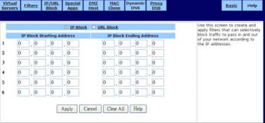
˙IP/URL Block
IP Block
Use the IP Block screen to create and apply filters to selectively block traffic from specific IP
addresses from passing in and out of your network.
You can block a single IP address or a range of IP addresses. If the IP address in the left IP field
(the From field) is the same as the IP address in the right IP field (the To field), a single IP address
is blocked. The IP Block screen is shown in the figure below.
To block a range of IP addresses:
1. Select “IP Block” Page.
2. Type the first IP address of the range in the To field.
3. Type the last IP address of the range in the From field.
4. Click Apply to put your changes in effect, or click Cancel to undo your changes.
To remove a block against IP addresses:
For any IP block that you want to delete, type 0.0.0.0 for both IP ranges and click Apply.
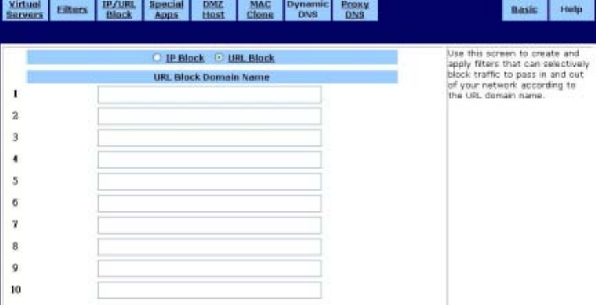
URL Block
URL Block can also be filtered by URL Address, the address entered to access Internet sites. The
URL Block screen is shown in the figure below.
39
To block a URL Address:
1. Select “URL Block” Page.
2. Type the URL Domain in “URL Block Domain Name” to field.
3. Click Apply to put your changes in effect, or click Cancel to undo your changes.
To remove a block URL Domain:
For any URL block that you want to delete, mark and delete the URL Domain and click Apply.
40
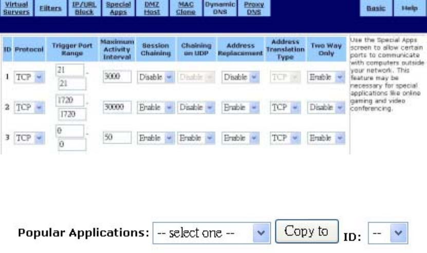
˙Special Apps
Use the Special Applications screen to allow certain ports to communicate with computers
outside your network. This feature may be necessary for multi-session applications like online
gaming and video conferencing. The Special Apps screen is shown in the figure below.
To configure Special Apps using the Popular Applications feature:
1. Select the application you wish to enable from the Popular Applications drop-down list:
2. Choose a specific line in the table by selecting its number from the ID drop-down list.
3. Click Copy to. The configuration settings for the selected application will appear in the table.
4. Click Apply to put your changes in effect, or click Cancel to undo your changes.
Manual Configuration
Although you can manually configure special applications, only expert users should do so. We
recommend that you always use the Popular Applications feature unless you know exactly
which settings to choose.
To manually configure Special Apps:
1. Choose a line item to configure.
2. Select the communication Protocol used by the application from the drop-down list (TCP,
UDP, or Both).
3. Specify a Trigger Port Range. This parameter identifies the range of ports that, when used
for outgoing traffic, will trigger the gateway to accept certain incoming requests.
4. Type a Maximum Activity Interval. This parameter specifies the maximum number of
41
milliseconds after the port trigger action during which incoming requests will be accepted.
5. Choose Enable or Disable from the drop-down list for Session Chaining. This parameter
specifies whether or not dynamic sessions can be chained, allowing multi-level session
triggering.
6. If you chose Enable in Step 5, you may now choose Enable or Disable for Chaining on UDP.
If you chose Disable in Step 5, skip to Step 7.
7. Choose Enable or Disable from the drop-down list for Address Replacement. This
parameter specifies whether or not binary address replacement should be performed.
8. If you chose Enable in Step 7, you may now choose the Address Translation Type (TCP or
UDP). If you chose Disable in Step 7, skip to Step 9.
9. Choose Enable or Disable from the drop-down list for Multi Hosts. Enabling this parameter
allows a new session to be initiated from/to different remote hosts.
10. Click Apply to put your changes in effect, or click Cancel to undo your changes.
To delete a special application:
1. Enter 0 - 0 for Trigger Port Range.
2. Click Apply.
42
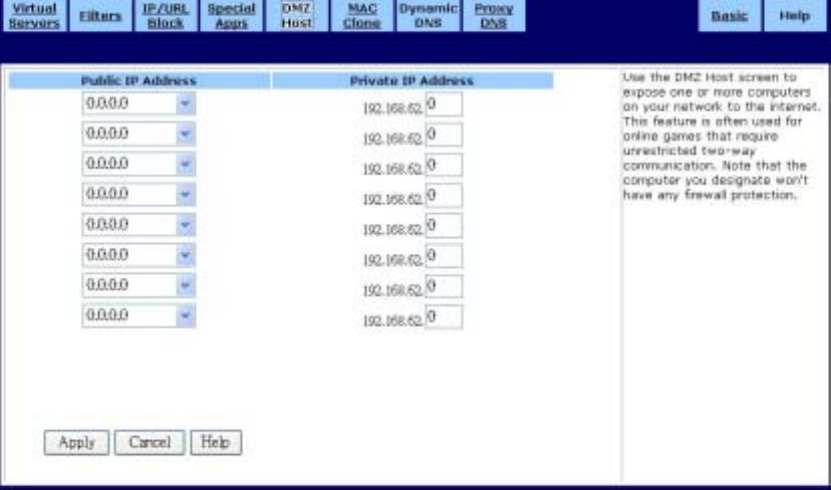
˙DMZ Host
Use the DMZ Host screen to expose one or more computers on your network to the Internet.
This feature is often used for online games that require unrestricted two-way communication.
The total number of DMZ hosts you can have is limited by the total number of Global
Addresses that you have configured in the Global Address screen. For example, if you have
defined five Global Addresses (including the Default Public IP), you are limited to five DMZ
hosts. The DMZ Host screen is shown in the figure below.
To set up a computer on your network as a DMZ Host:
1. Select a Public IP Address from the drop-down list.
2. Specify the Private IP Address. You only need to type the last part of the address; the first
part is set automatically.
3. Click Apply to put your changes in effect, or click Cancel to undo your changes.
To delete DMZ Hosts:
For any DMZ Host you want to delete, select 0.0.0.0 for Public IP Address and click Apply.
43
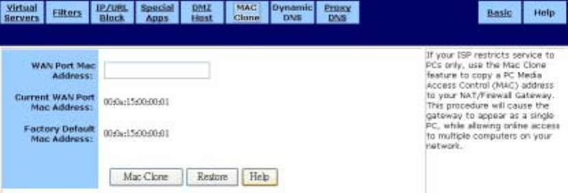
˙MAC Clone
If your ISP restricts service to PCs only, use the MAC Clone feature to copy a PC Media
Access Control (MAC) address to your router. This procedure will cause the router to appear
as a single PC, while allowing online access to multiple computers on your network. The MAC
Clone screen is shown in the figure below.
To clone the MAC address:
1. Type a PC MAC Address in the WAN Port Mac Address field. You may need to use the
Ethernet MAC Address of the Network Interface Card (NIC) from the PC that is registered
with your ISP.
2. Click Mac Clone to put your changes in effect, or click Restore to undo your changes.
44
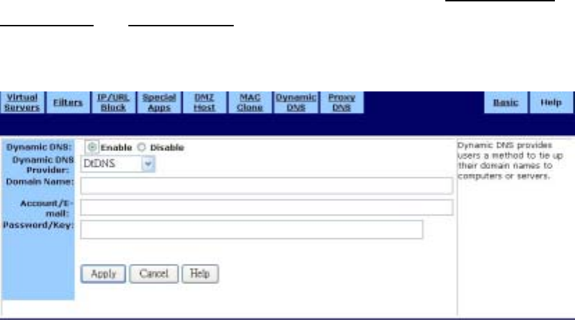
˙Dynamic DNS
Use the Dynamic DNS screen to map your domain names to DNS servers connected via DSL,
PPPoE, or another service that does not provide users with static IP addresses.
When you register the Wireless-G Router with the dynamic DNS service and connect to the
Internet using a dynamic IP address, the dynamic DNS service works with the DNS server to
forward the correct IP address to the requestor. These providers allow you to associate a static
hostname with a dynamic IP address. This allows you to connect to the Internet with a dynamic
IP address and use applications that require a static IP address.
The Wireless-G Router supports the following dynamic DNS providers: DynDNS.org,
no-IP.com, and DtDNS. For more information about these providers, see www.DynDNS.org,
www.no-IP.com, and www.DtDNS.com.
The Dynamic DNS screen is shown in the figure below.
To configure a dynamic dns server:
1. On the Dynamic DNS screen, click Enable.
2. Select a Dynamic DNS Provider from the list (DynDNS.org, no-IP.com, or DtDNS).
3. Type your Domain Name.
4. Type your Account or E-mail address.
5. Type the Password or Key for your account or E-mail address.
45
6. Click Apply to put your changes in effect, or click Cancel to undo your changes.
46
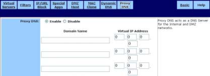
˙Proxy DNS
Use the Proxy DNS screen to map a domain name to its server’s IP address. This feature acts
as a DNS server for the internal and DMZ networks, allowing you to connect to local machines
without using an external DNS server. This simplifies network configuration and management.
The Proxy DNS screen is shown in the figure below.
To configure a Proxy DNS server:
1. On the DHCP screen, click Enable.
2. Type a name for the local machine in the Domain Name field.
3. Type the IP address of the local machine in the Virtual IP Address field.
4. Click Apply to put your changes in effect, or click Cancel to undo your changes.
To delete a Proxy DNS server:
1. Delete the domain name of the proxy DNS server that you want to remove.
2. Type 0.0.0.0 for Virtual IP Address.
3. Click Apply to put your changes in effect, or click Cancel to undo your changes.
47
Federal Communication Commission Interference Statement
This equipment has been tested and found to comply with the limits for a Class
B digital device, pursuant to Part 15 of the FCC Rules. These limits are
designed to provide reasonable protection against harmful interference in a
residential installation. This equipment generates, uses and can radiate radio
frequency energy and, if not installed and used in accordance with the
instructions, may cause harmful interference to radio communications.
However, there is no guarantee that interference will not occur in a particular
installation. If this equipment does cause harmful interference to radio or
television reception, which can be determined by turning the equipment off and
on, the user is encouraged to try to correct the interference by one of the
following measures:
- Reorient or relocate the receiving antenna.
- Increase the separation between the equipment and receiver.
- Connect the equipment into an outlet on a circuit different from that
to which the receiver is connected.
- Consult the dealer or an experienced radio/TV technician for help.
This device complies with Part 15 of the FCC Rules. Operation is subject to the following two
conditions: (1) This device may not cause harmful interference, and (2) this device must
accept any interference received, including interference that may cause undesired operation.
FCC Caution: Any changes or modifications not expressly approved by the party responsible
for compliance could void the user's authority to operate this equipment.
IMPORTANT NOTE:
FCC Radiation Exposure Statement:
This equipment complies with FCC radiation exposure limits set forth for an uncontrolled
environment. This equipment should be installed and operated with minimum distance 20cm
between the radiator & your body.
This transmitter must not be co-located or operating in conjunction with any other antenna or
transmitter.
Cnet declared that CWR-854 is limited in CH1~11 from 2400 to 2483.5 MHz by specified
firmware controlled in USA.