COBAN Technologies M700SERIESVMDC Digital video recorder, computer for law enforcement User Manual M700 Hardware Install Manual
COBAN Technologies, Inc. Digital video recorder, computer for law enforcement M700 Hardware Install Manual
Contents
- 1. User Manual
- 2. User manual
User manual

COBAN M700
Installation Manual
Table of Contents
Introduction ..................................................................................................................................................................... 3
Warnings and Safety Issues .......................................................................................................................................... 4
Tools and Electrical Parts List ...................................................................................................................................... 6
CPU Installation .............................................................................................................................................................. 7
Plywood Deck Mount ............................................................................................................................................. 7
Tray Mount ............................................................................................................................................................ 9
Camera Installation ....................................................................................................................................................... 10
Monitor Installation ....................................................................................................................................................... 12
Optional COBAN Accessories ..................................................................................................................................... 13
Drivers License Card Reader ........................................................................................................................................ 13
Crash Sensor ................................................................................................................................................................ 13
GPS ............................................................................................................................................................................... 14
Fixed Mount Antenna with Low Loss Cable (for Wireless Upload) ............................................................................... 14
Dual Receivers .............................................................................................................................................................. 14
Wide Angle Camera ...................................................................................................................................................... 15

Introduction
COBAN manufactures state-of-the-art Mobile Data Computers and Digital Video Recording Equipment for use in
the Public Safety, Utility and Military community. In addition to innovative mobile computing devices and digital
video technology, COBAN employs the latest communication, database, and storage technologies to deliver
complete and scalable solutions to our customers, regardless of the size of the agency.
Due to variations in vehicles, Agency equipment requirements, and the placement of existing equipment, every
installation in a Public Safety Vehicle is unique. This Manual assumes, and illustrates, installations in Ford Crown
Victoria, Chevy Impala, Silverado and Tahoe, as well as Dodge Charger and Magnum.
The information contained herein is subject to change without notice. COBAN Technologies reserves the right to
make changes to this product, has no obligation to update or keep current the information contained within, and
assumes no responsibility for any errors or omissions that may be present in this document.
Manual Name: COBAN Technologies – M700 Hardware Installation Manual
Company Information: COBAN Technologies® Incorporated
12503 Exchange Drive, Suite # 536
Stafford, Texas 77477
Tel: 1-281-277-8288
Fax: 1-281-277-8256
UNDER NO CIRCUMSTANCES WILL COBAN TECHNOLOGIES BE LIABLE FOR ANY LOSS OR DAMAGES
RESULTING FROM THE USE OF THIS MANUAL.
FOR HELP WITH ANY QUESTIONS REGARDING INSTALLATION OR THE USE OF THIS MANUAL, PLEASE
CONTACT COBAN SUPPORT AT: 281-277-8288

Warnings and Safety Issues
Failure to properly install, operate, and care for the COBAN System can increase the risk of ELECTRIC
SHOCK or FIRE. Failure to properly install and secure the COBAN System in accordance with this manual
can increase the risk of any component becoming dislodged from its mounting structure and may possibly
result in SERIOUS INJURY or DEATH to the VEHICLE PASSENGERS, or DAMAGE TO THE COBAN
SYSTEM.
Do not expose any Component of the COBAN System to Liquid or Moisture.
- Do not install this apparatus near water or expose it to rain, moisture, chemicals, and dripping or splashing
liquids of any type
- Do not clean the COBAN System with water, liquid cleaners, solvents, or aerosols
Prevent the COBAN System from overheating.
- Do not block any Ventilation Openings
- Install in a well-ventilated area
- Do not place the COBAN System near any soft surface that may block ventilation openings
- Do not install near any heat sources or any apparatus that produces heat
Stay away from DANGEROUS VOLTAGE inside the COBAN System, DO NOT take the COBAN System
Apart.
- Contact with energized parts inside the COBAN System can cause SERIOUS INJURY or DEATH from
ELECTRIC SHOCK
- Do not attempt to service, modify, repair, or tamper with the COBAN System
- Refer all Servicing to the COBAN Customer Service Department or COBAN Authorized Service Personnel
Avoid damaging any electrical Wires or Cables.
- Protect the Cables from being stepped on or pinched, particularly at Plugs, and the point where they exit from
the apparatus
- Do not jerk, knot, sharply bend, or otherwise abuse the Cables
- Do not expose Cables or electrical Wiring to sources of Heat
- When connecting and disconnecting Plugs, PULL ON THE PLUGS, DO NOT PULL ON THE CABLE, and be
sure to check the alignment of the Pins for damage prior to plugging them in
- Arrange all Connectors and Cables so that passengers are not likely to trip over them or accidently pull on them
as they move around, or enter and exit the vehicle
- If any Cable or Wire becomes damaged in any way, immediately discontinue use of the COBAN System and
call the COBAN Customer Service Department or COBAN Authorized Service Personnel
Only use COBAN approved and authorized Attachments, Accessories, and Peripherals.
Always disconnect the Vehicle Battery Ground Lead prior to installing any Component.
Always remove the fuse at the 12v positive Battery Terminal before Jump-starting or Charging the Battery
while it is still in the Vehicle
The USER acknowlM700s and understands that the installation of after-market equipment in motor vehicles
can compromise a vehicle's safety-related design characteristics, including but not limited to:
- Airbags, including but not limited to potential obstruction of airbag deployment;
- Front and Rear Passenger compartments, including but not limited to potential for ergonomic problems,
physical obstacles, etc.
- Trunk/gas tank protection, including but not limited to the potential for trunk-mounted equipment to exacerbate
tank vulnerability in a rear collision.
COBAN shall bear no liability whatsoever for any claims, expenses, losses or costs relating to the safety of any
equipment provided hereunder or the safety of any installations thereof.
Digital Video Surveillance Systems, including in-vehicle systems, offer new functionality and added convenience,
but they may also introduce some unique security and privacy exposures. These exposures include, but are not
limited to, policies and operating procedures related to: a) the capture, transfer, and management of digital images;
b) the use of these digital images in legal proceedings; and c) the use of these digital images for other purposes.
Numerous techniques are available that may mitigate some of these unique security and privacy risks, including
ensuring that security reliance is not placed solely on the system, and that the system and resulting images are
used only in compliance with comprehensive department policies and standard operating procedures. The USER
acknowlM700s and understands that the USER is solely responsible for developing, implementing and maintaining
appropriate Security and Privacy Policies and operating procedures for the system(s) described in this SOW, and
ensuring on-going compliance with them.
COBAN shall bear no liability whatsoever for, and the USER hereby fully, irrevocably and unconditionally release
COBAN and its successors and assigns from, any claims, expenses, losses, or costs relating to the USER’s use of
the materials, system or services provided by COBAN hereunder, including any claims based on the content of any
information captured on any video recorder provided hereunder. The USER will be solely responsible for any and
all such claims made against COBAN which are based on the USER’s use of the materials, system or services
provided by COBAN hereunder,
The USER acknowlM700s and agrees that COBANs performance hereunder does not include any obligation to
provide testimony or other evidence of any kind in any legal, regulatory, administrative or other proceeding
excluding subpoenas issued by judge or court of law. In the event that COBAN is requested by the “Department or
the USER” to be the expert witness to provide testimony or any evidence of any kind in connection with its
performance hereunder, whether required by the USER or any other third party, the USER agrees to pay COBAN’s
time and materials rates plus COBAN’s actual expenses incurred in the provision of such testimony or evidence.

Tools and Electrical Parts List
COBAN DOES NOT supply Tools and Materials for installations. Due to the uniqueness of every installation,
COBAN cannot predict exactly what tools, electrical connectors, or hardware may be necessary for each individual
installation. COBAN provides a connector kit and hardware kit that includes the basic connectors and hardware for
most installs, however this may not cover every installation. It is recommended that the installing technicians have a
ready supply of these basic tools and supplies on hand:
8” x 12” x 3/4" thick - plywood
Liquid Nail™ adhesive (this brand only)
Power drill (12V minimum)
Drill bits (various sizes)
5/16” driver bit
#20 TORX™ bit
7/16”” socket with ratchet (full socket set is recommended)
7/16”” wrench
Adjustable wrench
Phillips screwdriver
Wire cutters
Wire crimpers
3/4” antenna hole saw
Razor knife
Windproof lighter (for shrink terminals)
Wire fish
Electrical tape
Silicone sealant (to seal grommet in firewall, after wire is run through it)
Assortment of fuses
16AWG stranded primary wire
14AWG stranded primary wire
Various sizes of cable zip ties
Various sizes of wire loom
Various sizes and types of electrical connectors
Note: COBAN requires the use of shrink type connectors only for waterproofing purposes; please remember to
apply heat to shrink the ends of the connectors. Failure to shrink these connectors as prescribed may result in
VOIDING THE COBAN WARRANTY if there is exposure to corrosion or moisture in these electrical connections.
WARNING: The use of “Vampire Clips” and “Scotch Locks” is NOT ALLOWED by COBAN due to frequent failure
and connectivity degradation over time, and said use thereof will VOID THE COBAN WARRANTY, unless the
following criteria are followed explicitly:
- Only allowed when used to tap into the vehicle factory wire harness
- Only 3M™ brand T-taps and spades are allowed
- Allowed for use to tap into only the factory wire harness of the brake sensor circuit, gunlock sensor circuit, and
door sensor circuits
In addition to the installation of these specified taps, each connection will be further secured by wrapping with
electrical tape, cold shrink tape, or heat shrink tubing.
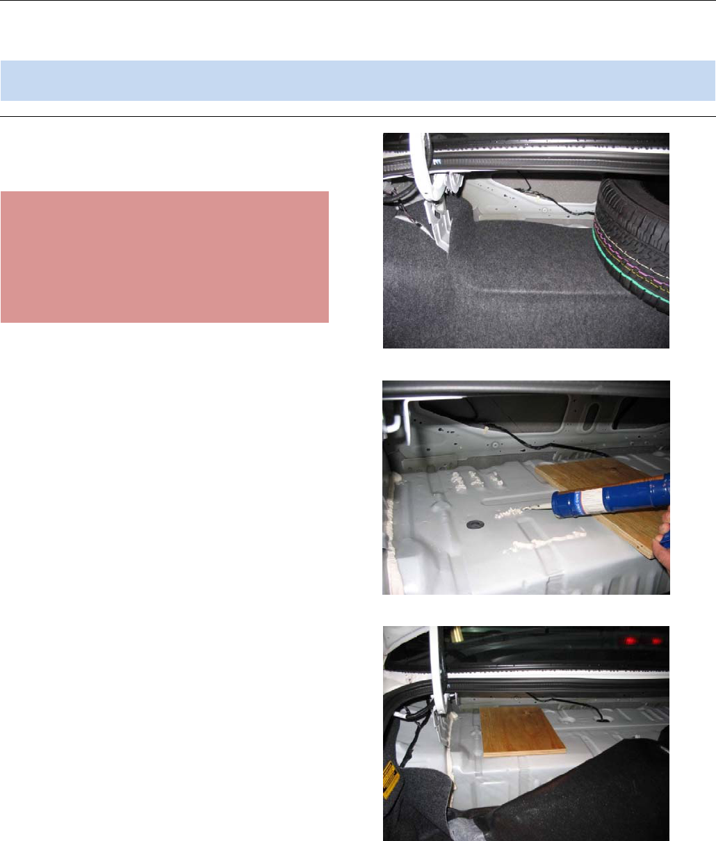
CPU Installation
The CPU and Smart Power Module should be mounted directly on the pullout tray in the trunk. If there is no tray
available; the Components should be mounting on a piece of plywood at least three quarter inch (3/4”) thick, which
could be glued to the Deck above the fuel tank.
Note: COBAN Technologies WILL NOT take responsibility for a DAMAGED FUEL TANK if units are installed by a
Third Party Contractor or Fleet Personnel.
Plywood Deck Mount
1. Locate an appropriate space on the Trunk
Deck for mounting the Smart Power Module.
WARNING: The Installation Technician MUST
ensure that the installation of the CPU mount does
not in any way compromise the integrity of the
vehicle’s Fuel Tank. Be sure that the fastening
screws are not longer than the thickness of the
Plywood. Use the recommended glue, as fast drying
glues become brittle, and can easily vibrate loose
from the Deck surface.
2. Remove the carpeting covering the hole
plug.
3. Apply adequate amount of Liquid Nail to the
mounting surface.
4. Press a piece of plywood (minimum 3/4”
thick) firmly onto the glue.
5. Replace the carpet over the plywood, and
allow sufficient time for the glue to set.
WARNING: Liquid Nail™ requires 8 hours to set,
and 24 hours to completely cure. It is not
recommended to release the vehicle back into
service before the full curing time has been reached.
LIQUID NAIL™ IS HIGHLY FLAMMABLE AND
SHOULD NOT BE EXPOSED TO OPEN FLAME
OR SPARKS BEFORE THE FULL CURING TIME
HAS BEEN REACHED.
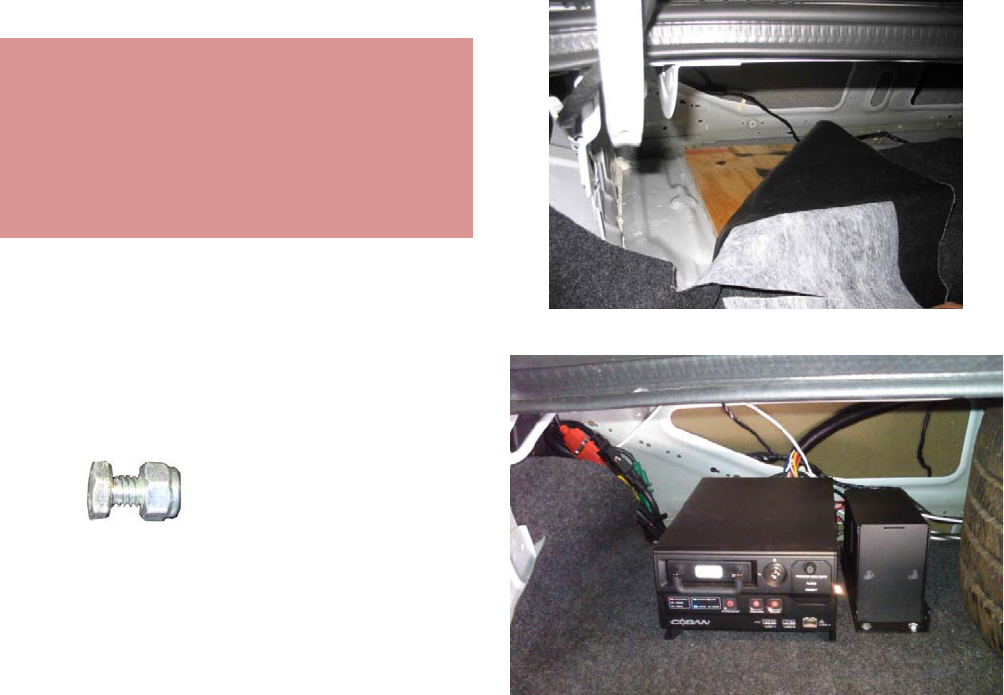
6. The four ( 4 ) ¼ -20 x ½” hex head bolts with
nylon threaded nuts slide into the grooves in
the railing of the CPU and secure it to the
CPU Mount.
7. Tighten the four ( 4 )¼ -20 x ½” hex head
bolts with nylon threaded nuts with a
crescent wrench and ensure that the CPU is
secured in place.
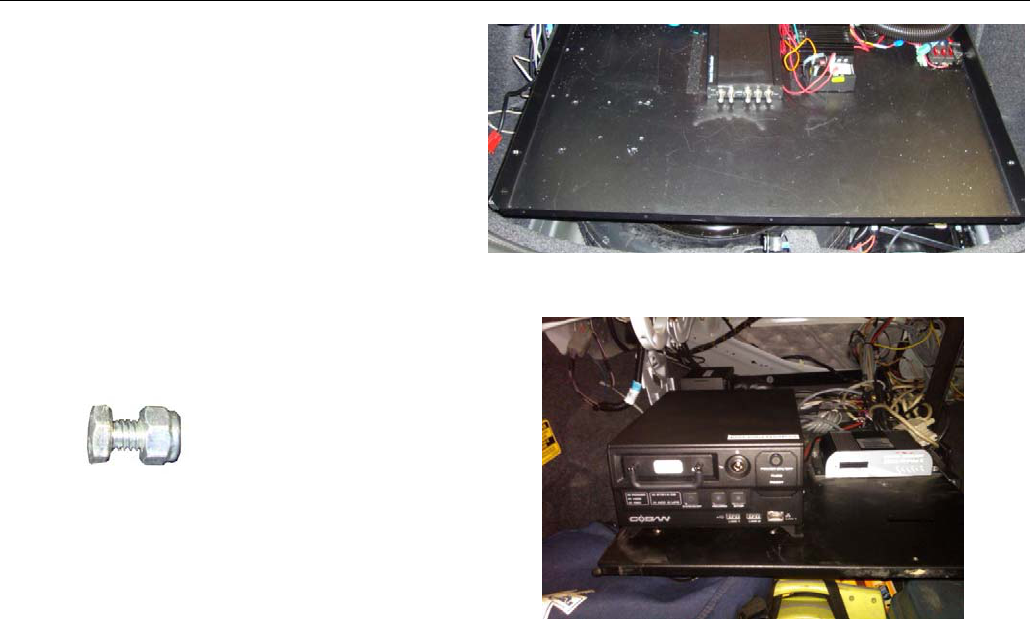
Tray Mount
1. Set the CPU Mount onto the sliding tray and
mark the position for pilot holes.
2. Use a
5/16” metal drill bit to drill the four
pilot holes in the sliding metal tray.
3. The four ( 4 ) ¼ -20 x ½” hex head bolts with
nylon threaded nuts slide into the grooves in
the railing of the CPU and secure it to the
CPU Mount.
4. Tighten the four ( 4 )¼ -20 x ½” hex head
bolts with nylon threaded nuts with a
crescent wrench and ensure that the CPU is
secured in place.
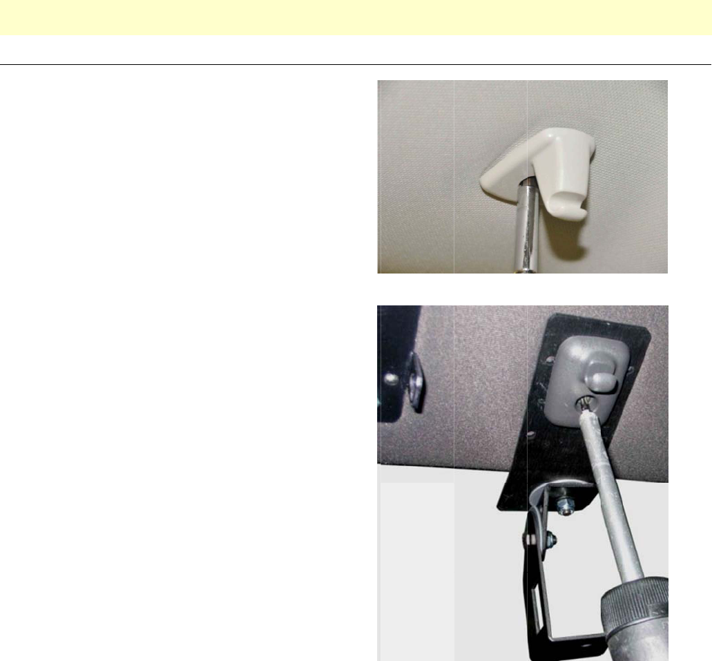
C
T
M
b
C
C
i
s
N
C
ame
r
T
he camera
m
M
700 system
b
e followed f
o
C
OBAN Tec
h
C
AUTION: C
O
s
caused to t
N
ote:
1. Rem
o
Visor
2. Use t
temp
o
r
a Ins
m
ount install
a
in an overh
e
o
r installatio
n
h
nologies for
O
BAN Tech
n
he windshiel
o
ve the scre
w
Clip.
he passeng
e
o
rarily secur
e
tallati
o
a
tion proced
u
e
ad/visor ori
e
n
of the M70
0
more detail
s
n
ologies will
d by a third
p
w
from the p
a
e
r side Visor
e
the Camer
a
o
n
u
re describe
d
e
ntation in a
0
system on
o
s
on your sp
e
not assume
p
arty installe
r
a
ssenger sid
Clip to
a
Mount.
d
in the follo
w
Ford Crown
o
ther types
o
e
cific vehicle
any respons
r
during the i
e
w
ing steps
w
Victoria. Dif
f
o
f vehicles. F
type and ori
e
ibility or liabi
nstallation p
r
w
as captured
f
erent install
a
or more info
r
e
ntation.
lity in the ev
e
r
ocess.
du
r
ing the i
n
a
tion proced
u
r
mation plea
s
e
nt that any
t
n
stallation of
u
res will nee
d
s
e contact
t
ype of dam
a
the
d
to
a
ge
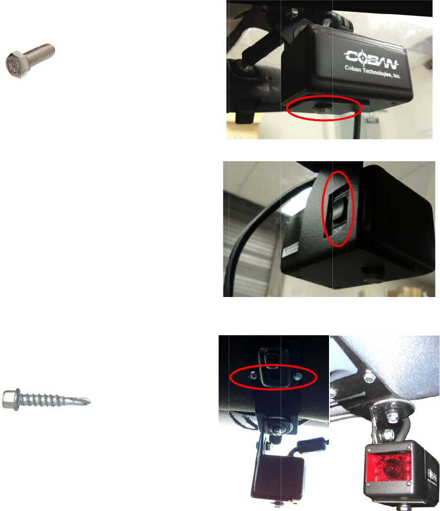
3. Secu
r
with t
wash
4. Ensu
r
situa
t
be a
c
5.
A
dju
s
secu
r
with t
tappi
n
r
e the Came
he supplied
¼
er.
r
e that the z
o
t
ed in the Ca
c
tivated by th
s
t the camer
a
r
e the Came
r
he two (2) p
r
n
g screws.
ra to the Ca
m
¼
- 20 x ½”
b
o
om switch i
s
mera Mount
e driver.
a
to the opti
m
r
a Mount to t
r
ovided #10-
m
era Mount
b
olt and
s
correctly
Arm so it ca
m
al position,
he headline
r
16 x 1 ¼” se
n
r
l
f
-
Monitor Installation
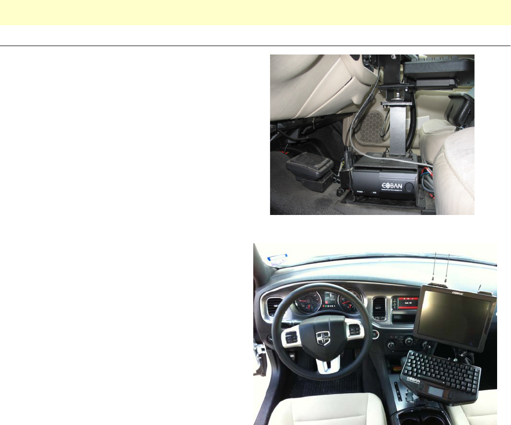
The Monitor installation procedure described in the following steps was captured during the installation of the M700
system in a Ford Crown Victoria. Different installation procedures will need to be followed for installation of the M700
system on other types of vehicles. For more information please contact COBAN Technologies for more details on
your specific vehicle type and orientation.
CAUTION: COBAN Technologies will not assume any responsibility or liability in the event that any type of damage
is caused to the windshield by a third party installer during the installation process.
Note:
1. The Department will need to use its existing
Laptop / MDC Mounts, or procure an
additional Pedestal Mount to support
COBAN’s Monitor and Keyboard mounts.
2. Department may choose to mount the
Monitor/Keyboard assembly on the
existing Laptop/MDC Mounts already in
the Vehicle
3. Department may choose to mount the
Monitor/Keyboard assembly on a
Pedestal/MDC Mount procured through,
or designed by, COBAN
NOTE:
COBAN does NOT supply any Hardware or
Mounting Components below the VMDT Monitor
and Keyboard Mounts. The Department will need
to use its existing Laptop/MDC mounts, or
procure an additional MDC/Pedestal Mount to
support COBANs’ Monitor and Keyboard
Mounts.
O
D
C
O
ptio
n
D
rive
r
Lic
e
1. COB
A
Side
d
for m
o
2. The
C
USB
som
e
Port
o
C
rash Sen
1. This
A
of th
e
‘Eme
r
Vic’s
)
the p
a
2. This
C
verti
c
fram
e
easil
y
even
t
3. The
C
COB
A
12v
P
Splic
e
Pow
e
12v
P
Splic
e
Wire
4. Depr
e
Sens
o
Syst
e
into s
n
al C
O
e
nse Card
A
N recomm
e
d
Adhesive
T
o
unting this
A
C
ard Reader
Port on the
b
e
cases, it m
a
o
n the face
o
sor
A
ccessory is
e
Vehicle, pr
e
r
gency Fuel
)
or in the co
r
a
ssenger si
d
C
omponent
m
c
al position,
a
e
work of the
V
y
located by
t
t
that it need
s
C
rash Senso
A
N Power D
i
P
ower Senso
e
s to Blue ‘S
e
r Distributio
n
P
ower – Red
e
s into Red
w
Harness
e
ss the Plun
g
o
r after insta
e
m; and befo
s
ervice.
O
BAN
Reader
e
nds ‘Dual-L
o
T
ape’ (by 3M
™
A
ccessory.
will be plug
g
b
ack of the
M
a
y be plugge
d
o
f the CPU.
best mount
e
e
ferably nea
r
Cut-Off Swit
c
r
responding
d
e.
m
ust be mo
u
a
s level as p
o
V
ehicle Cha
s
t
he Vehicle
O
s
to be reset
.
r will be wire
i
stribution W
i
r – Blue Wir
e
pare’ wire o
n
n
Wire Harn
e
Wire
w
ire on Pow
e
g
er at the to
p
llation; befo
r
re the vehicl
e
A
cce
s
o
ck’ or ‘Dou
b
™
Products)
g
ed into the
M
onitor, or in
d into the U
S
e
d in the Tru
n
r
the
c
h’ (in Crow
n
location on
u
nted in a
o
ssible, to th
e
s
sis, and be
O
perator in t
h
.
d into the
i
re Harness.
e
n
e
ss
e
r Distributio
n
p
of the Cras
r
e testing the
e
is release
d
s
sori
e
b
le
S
B
n
k
n
e
h
e
n
h
d
12VPo
w
Sen
s
12VPowe
e
s
w
er
s
or
r
Mounti
Ta
ng
bs
P
P
lunger
G
F
C
D
T
c
W
i
n
s
s
P
W
T
A
c
I
n
F
G
PS
1. This
A
anyw
locati
Dash
2. COB
A
Side
d
for m
o
3. Plug
t
of th
e
F
ixed Mou
C
able (for
W
1. This
A
on th
e
from
t
the V
bar),
A
nte
n
2. This
A
conc
e
the A
3. The
L
away
Volta
g
and
W
4. COB
A
alon
g
code
d
5. This
A
of th
e
‘RP
S
D
ual Rece
i
T
his Accesso
c
omponents;
W
ireless Spli
t
n
to the Syst
e
hould take c
a
s
pecificall
y
d
P
lu
g)
and ‘P
a
W
ireless Rec
e
T
hree Feet (
3
A
ntennae poi
c
omponents
t
n
terference,
s
F
eedback).
A
ccessory c
a
here, althou
g
on is the on
t
board of the
A
N recomm
e
d
Adhesive
T
o
unting this
A
t
he GPS int
o
e
COBAN C
P
nt Anten
n
W
ireless
U
A
ccessory s
h
e
Trunk Lid (
t
he rear Win
d
ehicle (prefe
at least one
f
n
nae, or the
L
A
ntenna ope
e
pt, and nee
d
ccess Point.
L
ow Loss Ca
from any Hi
g
g
e equipme
n
W
iring as po
s
A
N recomm
e
g
the same r
o
d
cables.
A
ccessory w
e
CPU, near
t
S
MA Male’ c
o
i
vers
ry is compo
s
TWO Wirel
e
t
ter Box, whi
c
e
m prior to s
h
a
re to note t
h
d
esi
g
nated
a
a
ssen
g
er Si
e
ivers must
b
3
’) apart from
nting upwar
d
t
oo close tog
s
tatic in the
A
a
n be mount
e
g
h the reco
m
t
he passeng
e
Vehicle.
e
nds ‘Dual-L
o
T
ape’ (by 3M
™
A
ccessory.
o
the USB P
o
P
U.
n
a with Lo
w
U
pload)
h
ould be mo
u
at least one
d
shield), or
o
rably forwar
d
f
oot (1’) fro
m
L
ight-bar.
rates on the
d
s a clear p
a
ble should b
e
g
h Frequen
c
n
t and their r
e
s
sible.
e
nds routing
t
o
ute as the
C
ill be plugge
d
t
he Pig-Tails
o
nnector.
s
ed of three
(
e
ss Receiver
s
c
h is usually
h
ipping. The
h
at the Cabl
a
s ‘Driver S
i
de’
(
Gra
y
P
l
b
e vertically
each other,
d
s, (placing t
h
ether will ca
u
A
udio Recor
d
e
d almost
m
mended
er side
o
ck’ or ‘Dou
b
™
Products)
o
rt on the fac
w
Loss
u
nted either
foot (1’) aw
a
o
n the Roof
o
d
of the Ligh
t
m
any other
“line-of-sigh
t
a
th to locate
e
routed as
f
c
y or High
e
lated Cable
t
his cable
C
OBAN color
d
into the ba
c
, utilizing an
(
3)
s
, and the
integrated
Installer
es are
i
de’
(
Black
l
u
g)
. The
placed at le
a
with the
h
ese
u
se
d
ing, and
b
le
e
a
y
o
f
t
-
t
”
f
ar
s
c
k
a
st
LowL
o
Ante
n
Ca
b
LowPr
o
Ante
Sec
C
o
ss
n
na
b
le
o
file
nna
uring
C
ollar
O‐ring

Wide Angle Camera
This Camera is often used to view the Prisoners in
the rear passenger compartment; through the rear
Windshield; or passenger side windows of the
Vehicle. It utilizes a ‘Proprietary’ Camera mount
designed by COBAN, and should be secured firmly
to the side Structural Rib, or the Roll Bar of the
Prisoner Cage (mounting locations will vary
according to Department specifications).
As this is a Wide Angle Camera, some view
adjustments will need to be made by the Technician
during the testing phase and before releasing the
vehicle back into service.
This Accessory will be plugged into the designated
Color Coded Pig-Tail on the CPU (blue), or may
possibly be routed through a ‘Multi-Camera Junction
Box’ (depending on the number of Cameras being
installed in that particular vehicle), that will be
mounted near the CPU. COBAN will have Tags on
the Cables and the Multi-Camera Junction Box to
designate Camera 1, 2, or 3, and these Cameras
will be placed in locations designated by Department
specifications.
NOTE: This equipment has been tested and found to comply with the limits for a Class A
digital device, pursuant to Part 15 of the FCC Rules. These limits are designed to provide
reasonable protection against harmful interference when the equipment is operated in a
commercial environment. This equipment generates, uses, and can radiate radio
frequency energy and, if not installed and used in accordance with the instruction manual,
may cause harmful interference to radio communications. Operation of this equipment in
a residential area is likely to cause harmful interference in which case the user will be
required to correct the interference at his own expense.
This device complies with Part 15 of the FCC Rules. Operation is subject to the following
two conditions: (1) this device may not cause harmful interference, and (2) this device
must accept any interference received, including interference that may cause undesired
operation.
FCC Caution: Any changes or modifications not expressly approved by the party
responsible for compliance could void the user's authority to operate this equipment.
This device complies with Part 15 of the FCC Rules. Operation is subject to the following
two conditions: (1) This device may not cause harmful interference, and (2) this device
must accept any interference received, including interference that may cause undesired
operation.
This device is restricted to indoor use when operated in the 5.15 to 5.25 GHz frequency
range.
FCC Radiation Exposure Statement:
This equipment complies with FCC radiation exposure limits set forth for an uncontrolled
environment. This equipment should be installed and operated with minimum distance
20cm between the radiator & your body.