COLEMAN Heater, Kerosene Manual L0601037
User Manual: COLEMAN COLEMAN Heater, Kerosene Manual COLEMAN Heater, Kerosene Owner's Manual, COLEMAN Heater, Kerosene installation guides
Open the PDF directly: View PDF ![]() .
.
Page Count: 40
HIGH EFFICIENCY SEALED COMBUSTION
DRUM HEAT EXCHANGER SERIES
MODEL: DFAA/DFAH
(Oil and Gas Conversion Burner/
Single Stage Downflow Only)
66 - 84 MBH INPUT
(19.34 - 24.62 KW) INPUT
LIST OF SECTIONS
SAFETY ................................................ 1 SAFETY CONTROLS .................................... 22
DUCTWORK ............................................ 5 START-UP AND ADJUSTMENTS ........................... 23
FILTERS .............................................. 10 WIRING DIAGRAM - OIL-FIRED FURNACE .................. 27
OIL PIPING ............................................ 11 GAS GUN BURNER ...................................... 29
ELECTRICAL POWER ................................... 13 START-UP AND ADJUSTMENTS ........................... 33
VENT/COMBUSTION AIR SYSTEM ......................... 14 WIRING DIAGRAM - GAS CONVERSION BURNER ............ 38
LIST OF FIGURES
Label Location ................................................... 4
Dimensions ...................................................... 5
Air Distribution Systems ............................................ 7
Closet To Door Clearance - 6" or Greater .............................. 7
Furnace To Closet Door Clearance - 1" To 6" .......................... 7
Furnace To Closet Door Clearance - Less Than 1" . ...................... 7
Duct Connector Dimensions ......................................... 8
Recommended Floor Cut-out ........................................ 8
Duct Connector Depth ............................................. 8
Duct Connector Screw Attachment ................................... 8
Duct Connector Tab Attachment ..................................... 9
Anti-Backftow Damper ............................................. 9
Installation of Furnace ............................................. 9
Floor Installation ................................................. 10
Furnace Air Filters ............................................... 11
Oil Pump ....................................................... 12
One-Pipe System ................................................ 13
Two-Pipe System ................................................ 13
Solenoid Wiring .................................................. 13
Line Wiring Connections ........................................... 14
Wiring for Heat Only Thermostat .................................... 14
Wiring for Electronic Heat-Cool Thermostat ............................ 14
Wiring for Standard Heat-Cool Thermostat ............................ 14
ISO 9001
Ce4_fied Quality
Managemen_ System
For Installation In:
1. Manufactured (Mobile) Homes
2. Recreational Vehicles & Park Models
3. Modular Homes & Buildings
Wiring for Btend Air Accessory ..................................... 14
Elbow Assembly ................................................ 15
Combustion Air Inlet Pipe ......................................... 16
Combustion Air Inlet Pipe Alternate .................................. 16
Flue Shield Installation ............................................ 16
Roof Jack Attachment to Furnace ................................... 16
Standard Roof Jack .............................................. 18
Roof Jack With Removable Crowns ................................. 19
Installing Roof Jack Extension ...................................... 20
Ceiling Ring .................................................... 20
Home Layout ................................................... 21
Electrode Settings ............................................... 23
Oit Pump ...................................................... 24
Wiring Diagram for DFAA - Oil-Fired Furnace .......................... 27
Wiring Diagram for DFAH - Oil Furnace .............................. 28
Gas Piping ..................................................... 29
ManuaI Shut-off Valve/Gas Piping ................................... 30
Proper Piping Practice ............................................ 30
Gas VaIve ..................................................... 35
Reading Gas Pressure ........................................... 36
Electrode Orientation and Gap ..................................... 37
Wiring Diagram for DFAA - Gas Conversion Burner ..................... 38
Wiring Diagram for DFAH - Gas Gun ................................ 39
LIST OF TABLES
Timings and Settings ............................................. 22
Burner Specifications ............................................. 23
Filter Performance - Pressure Drop Inches W.C and (kPa) ............... 25
Blower Performance CFM ......................................... 25
Replacement Parts - Non Electrical .................................. 26
Gas Line Piping Size and Length ................................... 30
Length of Standard Pipe Threads in Inches (ram) ....................... 30
High Altitude Duration Chart ....................................... 32
Gas Burner Settings ............................................. 32
Inlet Gas Pressure Range ......................................... 35
Nominal Manifold Pressure ........................................ 35
Unit Clearances to Combustibles ..................................... 4
Minimum Duct Sizing For Proper Airflow ............................... 6
Round Duct Size ................................................. 6
Externat Static Pressure Range ...................................... 9
Filter Sizes ..................................................... 10
Burner Specifications ............................................. 11
Burner Rating at Elevation Above Sea Level, gph (I/m) ................... 12
Ratings & PhysicaI /Electrical Data .................................. 13
Roof Jack Options ............................................... 17
Cad CelI Resistance When Sensing Ftame ............................ 22
SECTION h SAFETY
This is a safety alert symbol. When you see this symbol on
labels or in manuals, be alert to the potential for personal
injury.
Understand and pay particular attention to the signal words DANGER,
WARNING, or CAUTION.
DANGER indicates an imminently hazardous situation, which, if not
avoided will result in death or serious injury.
WARNING indicates a potentially hazardous situation, which, if not
avoided could result in death or serious injury.
CAUTION indicates a potentially hazardous situation, which, if not
avoided may result in minor or moderate iniurv, It is also used to
alert against unsafe practices and hazards involving only property dam-
age.
,WARNING
Improper installation may create acondition where the operation of
the product could cause personal injury or property damage.
Improper llTstallation, adjustment, alteration, service or mainte-
nance can cause injury or property damage. Refer to this manual
for assistance or for additional information, consult a qualified con-
tractor, installer or service agency.
107272-UIM-A-0905
107272-UIM-A-0905
SPECIFIC SAFETY RULES AND PRECAUTIONS
1. U.S.....No. 1 or No. 2 heating oil only (ASTM D396),
CANADA.....No. 1 stove oil or No. 2 furnace oil only are approved
for use and can be burned in this furnace. Refer to the furnace rat-
ing plate or SECTION IV of these instructions.
2. Install this furnace only in a location and position as specified in
SECTION I of these instructions.
3. An oil-fired furnace for installation in a residential garage must be
installed as specified in SECTION I of these instructions.
4. Combustion products must be discharged outdoors. The Roof
Jack vent system is the only approved vent system that can be
installed on this furnace. Install as specified in SECTION VI of
these instructions.
FIRE OR EXPLOSION HAZARD
Failure to follow the safety warnings exactly could result in serious
injury, death or property damage.
Read aft instructions before proceeding. Follow al! instructions com-
pleteljz Failure to follow these instructions could result in equipment
malfunction, causing severe personal injury, death, or substantial
property damage.
5. Test for Ieaks in the oil Iine as specified in SECTION VI!I of these
instructions.
6. Always install the furnace to operate within the furnace's intended
temperature rise range. Only connect the furnace to a duct system
which has an external static pressure within the allowable range,
as specified on the furnace rating plate.
7. The return air duct system is not required by the furnace manufac-
turer. This furnace utilizes a sealed combustion air and vent sys-
tem referred to as a roof jack. The Roof Jack must be installed as
specified in these instructions and must conform with state, local,
or regional codes.
8. It is permitted to use the furnace for heating of buildings or struc-
tures under construction. Installation must comply with all manu-
facturer's installation instructions including:
• Proper vent installation;
• Furnace operating under thermostatic control;
• Return air filter door must be sealed to the furnace;
• Air filters in place;
• Set furnace input rate and temperature rise per rating plate
marking;
• Means for providing outdoor air required for combustion;
• Return air temperature maintained between 55°F (13°C) and
80°F (27°C);
• The air filter must be replaced or thoroughly cleaned upon sub-
stantial completion of the construction process;
• Clean furnace, duct work and components upon substantial
completion of the construction process, and verify furnace
operating conditions including ignition, input rate, temperature
rise and venting, according to the manufacturer's instructions.
The following requirements to be met:
a. Clean, outside combustion air is provided to the furnace to
minimize the impact of corrosive adhesives, sealants, and
other construction materials. Drywall dust is a major concern
during construction, which can be pulled into the combustion
air path, leading to plugged heat exchangers, burners, and
inducer assemblies.
b. Filter must be installed in the furnace as specified in the
installation instructions, and must be replaced or thoroughly
cleaned prior to occupancy of the home. Again, drywall dust
is the key issue, as that dust can be pulled into the circulating
blower motor, plugging the motor vents, coating the rotors
and stators, etc. which can lead to a potential fire hazard.
c. The temperature of the return air to the furnace must not be
less than 55° F (13 ° C), with no evening setback or furnace
shutdown, to prevent condensation in the primary heat
exchangers.
d. The air temperature rise must be within the stated rise range
as indicated on the furnace rating plate, and the firing input
rate must be set to the unit nameplate value.
e. The external static pressure of the air distribution system
ductwork must be set for heating operation to be at least 0.12
(.03 kPA) to 0.30 (0.7 kPA) inches water column, based on
the input rate of the furnace, with the lower value for input
rates at 66,000 btu/hr and the upper value for units with input
rates at 84,000 btu/hr.
f. The furnace and ductwork should be thoroughly and com-
pletely cleaned prior to occupancy of the dwelling to insure
the proper operation of the furnace and to avoid potential
health concerns.
9. In Canada refer to the Oil-fired Central Furnace Installation code,
CAN B40.9.3. When installed in a Manufactured (Mobile) Home,
combustion air shall not be supplied from occupied spaces.
10. The size of the unit should be based on an acceptable heat loss
calculation for the structure. ACCA, Manual J or other approved
methods may be used.
11. Manufactured (Mobile) Home and Modular Home Installation:
This appliance must be installed in a (sealed combustion) configu-
ration using a roof jack vent system. A roof jack is the only
approved vent system that can be used to vent this appliance.
12. Modular Home Definition: Factory-built home constructed to the
state, local, or regional code where the house will be located. The
home is transported in one or more modules and joined at the
home site.
13. Manufactured (Mobile) Home Definition: Factory-built home
constructed, transported and installed under the federal building
code administered by the U.S. Department of Housing and Urban
Development (HUD Code), rather than to building codes at their
destination. The house is built, transported and installed on a non-
removable chassis.
14. This furnace is approved for installation in trailers or recreational
vehicles.
SAFETY REQUIREMENTS
•Never attempt to alter or modify this furnace or any of its com-
ponents.
• Never attempt to repair damaged or inoperable components.
Such action could cause unsafe operation, explosion, fire and/
or asphyxiation.
• ff a malfunction has occurred, or ff you fee! that the furnace is
not operating as it should, contact a qualified service agency or
oil supplier for assistance.
•A manufactured (mobile) home installation must conform with the
Manufactured Home Construction and Safety Standard, Title 24
CFR, Part 3280, Federal Manufactured Home Construction &
Safety Standard (H.U.D., Title 24, Part 3280) or when such stan-
dard is not applicable, the standard for Manufactured Home
Installations (Manufactured Home Sites, Communities, and Set-
ups) NFPA 31 Installation of Oil-Burning Equipment, CANICSA
B139 Installation Codes). This furnace has been certified to the
latest edition of standard UL 727 Standard for Safety for Oil-Burn-
ing Equipment, and for Oil-Fired Central Furnaces (Latest Edi-
tion), CSA B140.!0 (Latest Edition), and all local codes and
ordinances.
•Refer to the unit rating plate for the furnace model number, and
then see the dimensions page of these instructions for return air
door dimensions in Figure 2. The filter(s) must be installed
according to the instructions.
2 Unitary Products Group
107272-UIM-A-0905
• Provide clearances from combustible materials as listed under
Furnace Locations and Clearances.
• Provide clearances for servicing, ensuring that service access is
allowed for both the burners and blower.
• These models are ETL listed and approved for installation into a
Modular Home or a Manufactured (Mobile) Home.
•Failure to carefully read and follow all instructions in this
manual can result in furnace malfunction, death, personal
injury and/or property damage.
• Furnaces for installation on combustible flooring shall net be
installed directly on carpeting, tile or other combustible material
other than wood flooring.
• Check the rating plate and power supply to be sure that the elec-
trical characteristics match. All models use nominal !15 VAC, 1
Phase, 60-Hertz power supply. DO NOT CONNECT THIS APPLI-
ANCE TO A 50 HZ POWER SUPPLY OR A VOLTAGE ABOVE
130 VOLTS.
• Furnace shall be installed so the electrical components are pro-
tected from water.
• Installing and servicing heating equipment can be hazardous due
to the electrical components and the oil fired components. Only
trained and qualified personnel should install, repair, or service oil
heating equipment. Untrained service personnel can perform
basic maintenance functions such as cleaning and replacing the
air filters. When working on heating equipment, observe precau-
tions in the manuals and on the labels attached to the unit and
other safety precautions that may apply.
NOTICE SPECIAL REQIREMENTS
kDANGER
This equipment must be installed, adjusted, and started only by a
qualified service agency -an individual or agency, licensed and
experienced with all codes and ordinances, who is responsible for
the installation and adjustment of the equipmenL The installation
must comply with all local codes and ordinances and with the latest
revision of the National Fire Protection Association Standard
NFPA31 (or CSA B139).
These instructions cover minimum requirements and conform to exist-
ing national standards and safety codes. In some instances these
instructions exceed certain local codes and ordinances, especially
those who have not kept up with changing Modular Home and Manu-
factured (Mobile) Home construction practices. These instructions are
required as a minimum for a safe installation.
COMBUSTION AIR QUALITY
(LIST OF CONTAMINANTS)
The furnace will require OUTDOOR AIR for combustion when the fur-
nace is located in any of the following environments.
Restricted Environments
Commercial buildings
Buildings with indoor pools
Laundry rooms
Hobby or craft rooms
Near chemical storage areas
Chemical exposure
The furnace will require OUTDOOR AIR for combustion when the fur-
nace is located in an area where the furnace is being exposed to the fol-
lowing substances and /or chemicals.
Permanent wave solutions
Chlorinated waxes and cleaners
Chlorine based swimming pool chemicals
Water softening chemicals
De-icing salts or chemicals
Carbon tetrachloride
Halogen type refrigerants
Cleaning solvents (such as perchloroethylene)
Printing inks, paint removers, varnishes, etc.
Hydrochloric acid
Cements and glues
Antistatic fabric softeners for clothes dryers
Masonry acid washing materials
When outdoor air is used for combustion, the combustion air intake duct
system termination must be located external to the building and in an
area where there will be no exposure to the substances listed above.
The furnace area must not be used as a broom closet or for any
other storage purposes, as a fire hazard may be created. Never
store items, such as the following, on, near or in contact with the
furnace.
1. Spray or aerosol cans, rags, brooms, dust mops, vacuum
cleaners or other cleaning tools.
2. Soap powders, bleaches, waxes or other cleaning com-
pounds; plastic items or
3. Containers, gasoline, kerosene, cigarette lighter fluid, dry
cleaning fluids or other volatile fluid.
4. Paint thinners and other painting compounds.
5. Paper bags, boxes or other paper products
Never operate the furnace with the blower door removed. To
do so could result in serious personal injury and/or equipment
damage.
INSPECTION
As soon as the furnace and/or accessories are received, it should be
inspected for damage during transit. If damage is evident, the extent of
the damage should be noted on the carrieCs freight bill. A separate
request for inspection by the carrier's agent should be made in writing.
Also, before installation, the furnace and/or accessories should be
checked for screws or bolts which have loosened in transit, or shipping
and spacer brackets that need to be removed.
CONCEALED DAMAGE -If you discover damage to the burner or
controls during unpacking, notify carrier at once and file the appro-
priate claim.
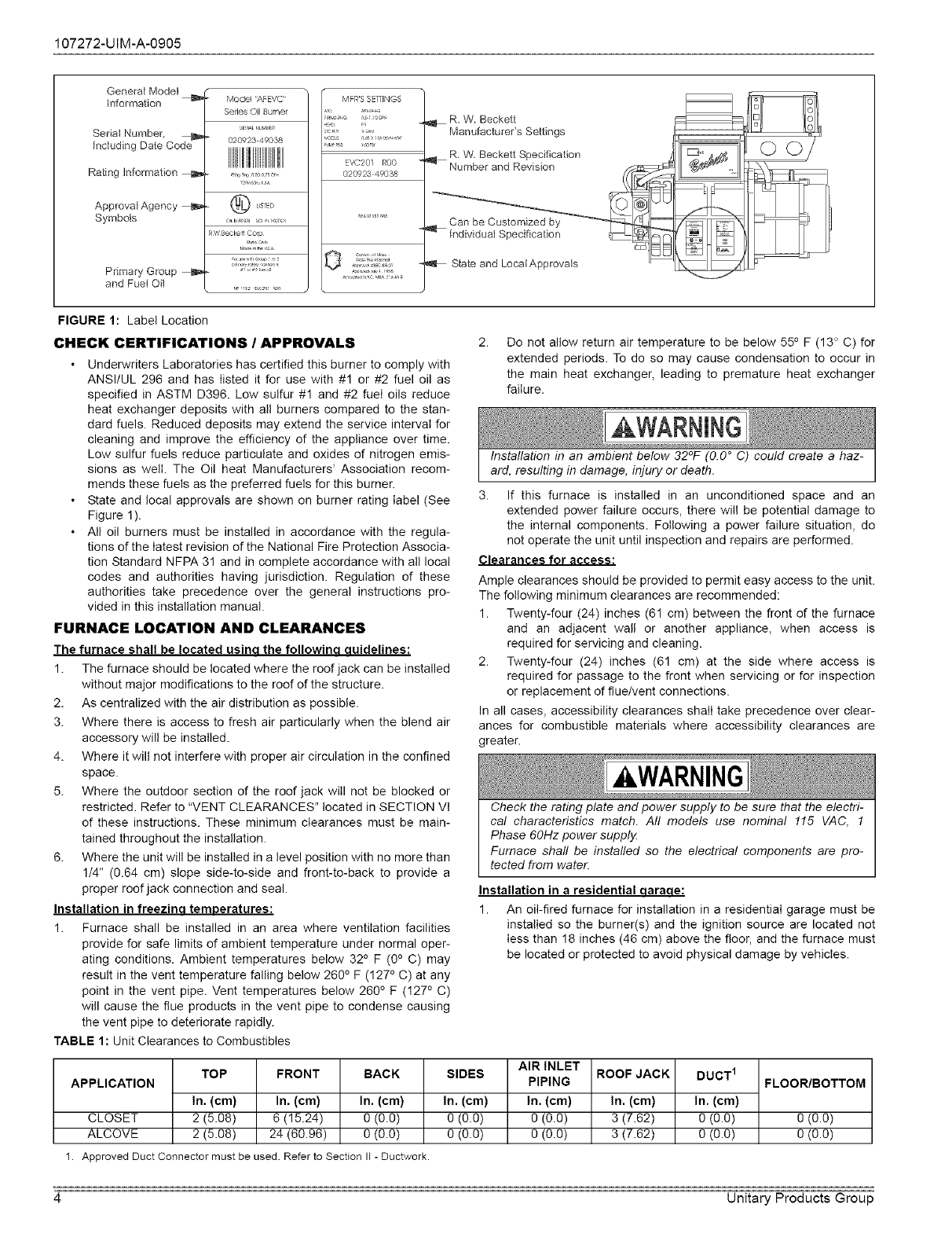
WHEN CONTACTING BECKETT FOR SERVICE INFORMATION -
Please record the burner serial number (and have available when
calling or writing). You will find the serial number on the Underwrit-
ers Laboratories label, located on the left rear of the burner, or
cover mounting plate. See Figure !.
Unitary Products Group 3
107272-UIM-A-0905
General Model
Information
Serial Number
including Date Code
Rating information
Approval Agency b,
Symbols
Primary Group b,,
and Fuet Oii
Model 'APEVC"
Series Oil Burner
sE_L,,LrJUMS_
02092349038
LIS! ED
RW BoXlike11Corp
MFR'S SETTINGS
,,J,_, s ,_/s
=VC201 R00
02g%_23 49038
o,,, s, o-_/
)
R. W, Beckett
ManufactureCs Settings
R,W, Beckett Specification
Number and Revision
Can be Customized by
Individual Specification
State and Locai Approvals
FIGURE 1: Label Location
CHECK CERTIFICATIONS /APPROVALS
• Underwriters Laboratories has certified this burner to comply with
ANSI/UL 296 and has listed it for use with #1 or #2 fuel oil as
specifed in ASTM D396. Low sulfur #1 and #2 fuel oils reduce
heat exchanger deposits with all burners compared to the stan-
dard fuels. Reduced deposits may extend the service interval for
cleaning and improve the efficiency of the appliance over time.
Low sulfur fuels reduce particulate and oxides of nitrogen emis-
sions as well. The Oil heat Manufacturers' Association recom-
mends these fuels as the preferred fuels for this burner.
• State and local approvals are shown on burner rating label (See
Figure 1).
• All oil burners must be installed in accordance with the regula-
tions of the latest revision of the National Fire Protection Associa-
tion Standard NFPA 31 and in complete accordance with all local
codes and authorities having jurisdiction. Regulation of these
authorities take precedence over the general instructions pro-
vided in this installation manual.
FURNACE LOCATION AND CLEARANCES
The furnace shall be located usina the followina auidelines:
1. The furnace should be located where the roof jack can be installed
without major modifications to the roof of the structure.
2. As centralized with the air distribution as possible.
3. Where there is access to fresh air particularly when the blend air
accessory will be installed.
4. Where it will not interfere with proper air circulation in the confined
space.
5. Where the outdoor section of the roof jack wiII not be blocked or
restricted. Refer to "VENT CLEARANCES" located in SECTION Vl
of these instructions. These minimum clearances must be main-
tained throughout the installation.
6. Where the unit will be installed in a level position with no more than
1/4" (0.64 cm) slope side-to-side and front-to-back to provide a
proper roof jack connection and seal.
Installation in freezina temoeratures:
1. Furnace shall be installed in an area where ventilation facilities
provide for safe limits of ambient temperature under normal oper-
ating conditions. Ambient temperatures below 32 ° F (0° C) may
result in the vent temperature falling below 260 ° F (127 ° C) at any
point in the vent pipe. Vent temperatures below 260 ° F (127 o C)
will cause the flue products in the vent pipe to condense causing
the vent pipe to deteriorate rapidly.
TABLE 1: Unit Clearances to Combustibles
Do not allow return air temperature to be below 550 F (13° C) for
extended periods. To do so may cause condensation to occur in
the main heat exchanger, leading to premature heat exchanger
failure.
Installation in an ambient below 32°F (0.0 °C) could create a haz-
ard, resulting in damage, injury or death.
3. If this furnace is installed in an unconditioned space and an
extended power failure occurs, there will be potential damage to
the internal components. Following a power failure situation, do
not operate the unit until inspection and repairs are performed.
Clearances for access:
Ample clearances should be provided to permit easy access to the unit.
The following minimum clearances are recommended:
1. Twenty-four (24) inches (61 cm) between the front of the furnace
and an adjacent wall or another appliance, when access is
required for servicing and cleaning.
2. Twenty-four (24) inches (61 cm) at the side where access is
required for passage to the front when servicing or for inspection
or replacement of flue/vent connections.
In all cases, accessibility clearances shall take precedence over clear-
ances for combustible materials where accessibility clearances are
greater.
kWARNING
Check the rating plate and power supply to be sure that the electri-
cal characteristics match. Al! models use nominal !15 VAC, 1
Phase 60Hz power supply
Furnace shall be installed so the electrical components are pro-
tected from water.
Installation in a residential aaraoe:
1. An oil-fired furnace for installation in a residential garage must be
installed so the burner(s) and the ignition source are located not
less than !8 inches (46 cm) above the floor, and the furnace must
be located or protected to avoid physical damage by vehicles.
APPLICATION
CLOSET
ALCOVE
TOP
In. (cm)
2 (5.08)
2 (5.08)
FRONT
In. (cm)
6 (15.24)
24 (60.96)
BACK
In. (cm)
0 (0.0)
0 (0.0)
SIDES
In. (cm)
0 (0.0)
0 (0.0)
AIR INLET
PIPING
In. (cm)
0(0.0)
o(0.0)
ROOFJACK
In, (cm)
3 (7.62)
3 (7.62)
DUCT 1
In. (cm)
0 (0.0)
0 (o.o)
FLOOR/BOTTOM
0 (0.0)
0 (0.0)
1. Approved Duct Connector must be used. Refer to Section II - Ductwork.
4Unitary Products Group
107272-UIM-A-0905
E
_'F
//
A
DFAH Series
I
__ I inches c.m.
A 59-1/2" 151.0
B- 76 '_ 193,0
C 24.3/4" 62.9
D 23" 58.4
E 19-1/2" 49.5
F 9-3/4 '_ 24.8
G- 12" 30.5
3" Etx. Static Duct Pressure --
No Coil -Std. Blower -High Speed
DFAA Series
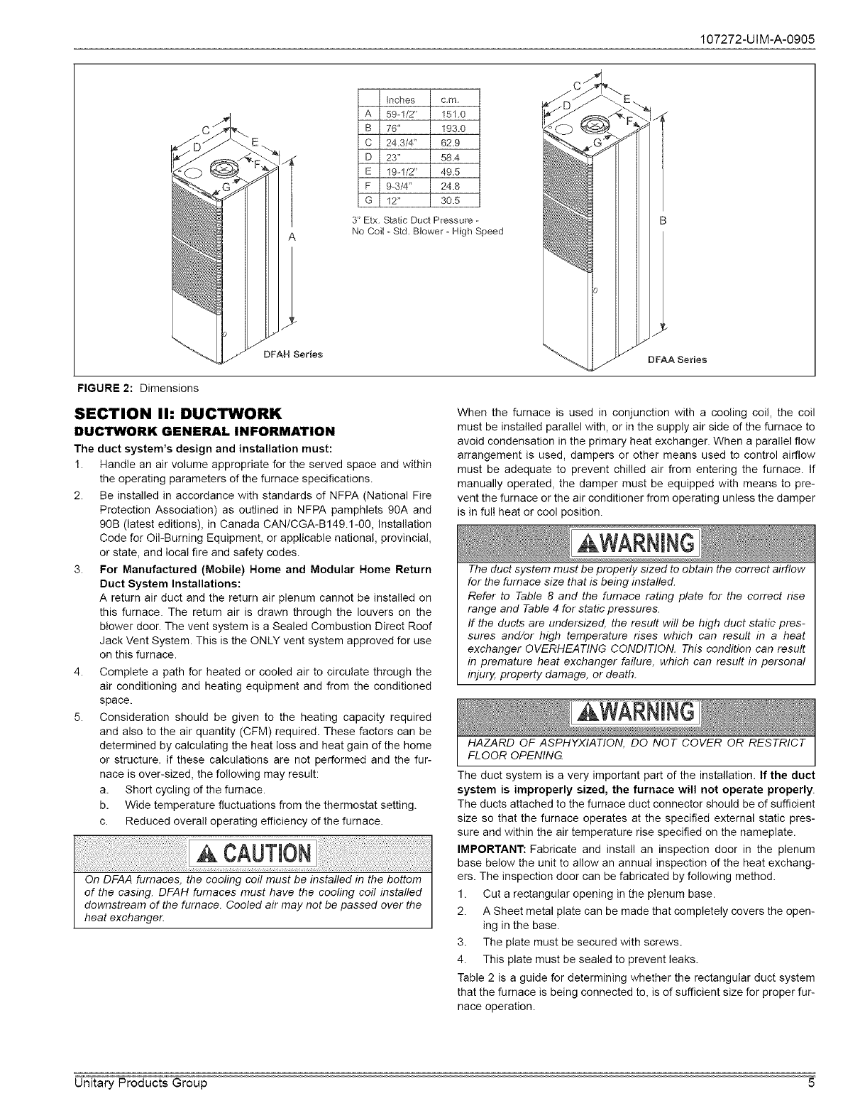
FIGURE 2: Dimensions
SECTION Ih DUCTWORK
DUCTWORK GENERAL INFORMATION
The duct system's design and installation must:
1. Handle an air volume appropriate for the served space and within
the operating parameters of the furnace specifications.
2. Be installed in accordance with standards of NFPA (National Fire
Protection Association) as outlined in NFPA pamphlets 90A and
90B (latest editions), in Canada CANiCGA-B149.1-00, Installation
Code for Oil-Burning Equipment, or applicable national, provincial,
or state, and local fire and safety codes.
3. For Manufactured (Mobile) Home and Modular Home Return
Duct System Installations:
A return air duct and the return air plenum cannot be installed on
this furnace. The return air is drawn through the louvers on the
blower door. The vent system is a Sealed Combustion Direct Roof
Jack Vent System. This is the ONLY vent system approved for use
on this furnace.
4. Complete a path for heated or cooled air to circulate through the
air conditioning and heating equipment and from the conditioned
space.
5. Consideration should be given to the heating capacity required
and also to the air quantity (CFM) required. These factors can be
determined by calculating the heat loss and heat gain of the home
or structure. If these calculations are not performed and the fur-
nace is over-sized, the following may result:
a. Short cycling of the furnace.
b. Wide temperature fluctuations from the thermostat setting.
c. Reduced overall operating efficiency of the furnace.
When the furnace is used in conjunction with a cooling coil, the coil
must be installed parallel with, or in the supply air side of the furnace to
avoid condensation in the primary heat exchanger. When a parallel flow
arrangement is used, dampers or other means used to control airflow
must be adequate to prevent chilled air from entering the furnace. If
manually operated, the damper must be equipped with means to pre-
vent the furnace or the air conditioner from operating unless the damper
is in full heat or cool position.
The duct system must be properly sized to obtain the correct airflow
for the furnace size that is being installed.
Refer to Table 8 and the fumace rating plate for the correct rise
range and Table 4 for static pressures.
If the ducts are undersized, the result wil! be high duct static pres-
sures and/or high temperature rises which can result in a heat
exchanger OVERHEATING CONDITION. This condition can result
in premature heat exchanger failure, which can result in personal
injury, property damage, or death.
HAZARD OF ASPHYXIATION, DO NOT COVER OR RESTRICT
FLOOR OPENING
The duct system is a very important part of the installation. If the duct
system is improperly sized, the furnace will not operate properly.
The ducts attached to the furnace duct connector should be of sufficient
size so that the furnace operates at the specified external static pres-
sure and within the air temperature rise specified on the nameplate.
IMPORTANT: Fabricate and install an inspection door in the plenum
base below the unit to allow an annual inspection of the heat exchang-
ers. The inspection door can be fabricated by following method.
1. Cut a rectangular opening in the plenum base.
2. A Sheet metal plate can be made that completely covers the open-
ing in the base.
3. The plate must be secured with screws.
4. This plate must be sealed to prevent leaks.
Table 2 is a guide for determining whether the rectangular duct system
that the furnace is being connected to, is of sufficient size for proper fur-
nace operation.
Unitary Products Group 5
107272-UIM-A-0905
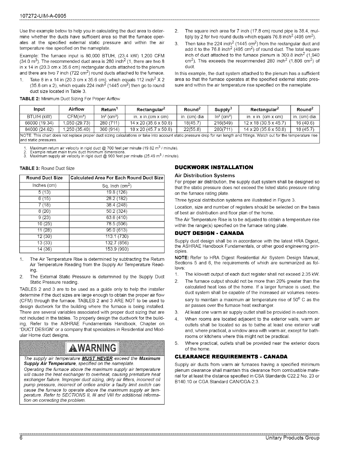
Use the example below to help you in calculating the duct area to deter-
mine whether the ducts have sufficient area so that the furnace oper-
ates at the specified external static pressure and within the air
temperature rise specified on the nameplate.
Example: The furnace input is 80,000 BTUH, (23.4 kW) 1,200 CFM
(34.0 m3). The recommended duct area is 280 inch 2 (!, there are two 8
in x 14 in (20.3 cm x 35.6 cm) rectangular ducts attached to the plenum
and there are two 7 inch (722 cm 2) round ducts attached to the furnace.
1. Take 8 in x 14 in (20.3 cm x 35.6 cm), which equals 112 inch 2X 2
(35.6 cm x 2), which equals 224 inch 2 (1445 cm 2) then go to round
duct size located in Table 3.
TABLE 2: Minimum Duct Sizing For Proper Airflow
2. The square inch area for 7 inch (!7.8 cm) round pipe is 38.4, mul-
tiply by 2 for two round ducts which equals 76.8 inch 2 (495 cm2).
3. Then take the 224 inch 2 (1445 cm2) from the rectangular duct and
add it to the 76.8 inch 2 (495 cm 2) of round duct. The total square
inch of duct attached to the furnace plenum is 300.8 inch 2 (1,940
cm2). This exceeds the recommended 280 inch 2 (1,806 cm 2) of
duct.
In this example, the duct system attached to the plenum has a sufficient
area so that the furnace operates at the specified external static pres-
sure and within the air temperature rise specified on the nameplate.
Input Airflow Return I Rectangular 2 Round 2 Supply 3 Rectangular 2Round 2
BTU/H (kW) CFM(m _) In =(cm =) in. x in.(cm x cm) in. (cm) dia In 2 (cm 2) in. x in. (cm x cm) in. (cm) dia.
66000 (19.34) 1,050 (29.73) 280 (71!) 14 x 20 (35.6 x 50.8) 18(45.7) 216(549) 12 x 18 (30.5 x 45.7) !6 (40.6)
84000 (24.62) 1,250 (35.40) 360 (914) 18 x 20 (45.7 x 50.8) 22(55.8) 280(7!1 ) 14 x 20 (35.6 x 50.8) 18 (45.7)
NOTE: This chart does not replace proper duct sizing calculations or take into account static pressure drop for rue length and fittings. Watch out for the temperature rise
and static pressures.
1. Maximum return air velocity in rigid duct @ 700 feet per minute (1982 m3 /minute).
2. Example return main trunk duct minimum dimensions.
3. Maximum supply air veIocity in rigid duct @ 900 feet per minute (2549 ms /minute).
TABLE 3: Round Duct Size
Round Duct Size Calculated Area For Each Round Duct Size
Inches (cm) Sq. Inch (cm 2)
5 (13) 19.8 (126)
6 (15) 28.2 (!82)
7 (18) 38.4 (248)
8 (20) 50.2 (324)
9 (23) 63.6 (410)
10 (25) 78.5 (5O6)
11 (28) 95.0 (613)
12 (30) 113.1 (730)
13 (33) !32.7 (856)
14 (36) !53.9 (993)
1. The Air Temperature Rise is determined by subtracting the Return
Air Temperature Reading from the Supply Air Temperature Read-
ing.
2. The External Static Pressure is determined by the Supply Duct
Static Pressure reading.
TABLES 2 and 3 are to be used as a guide only to help the installer
determine if the duct sizes are large enough to obtain the proper air flow
(CFM) through the furnace. TABLES 2 and 3 ARE NOT to be used to
design ductwork for the building where the furnace is being installed.
There are several variables associated with proper duct sizing that are
not included in the tables. To properly design the ductwork for the build-
ing, Refer to the ASHRAE Fundamentals Handbook, Chapter on
"DUCT DESIGN" or a company that specializes in Residential and Mod-
ular Home duct designs.
The supply air temperature MUST NEVER exceed the Maximum
Supply Air Temperature, specified on the nameplate.
Operating the furnace above the maximum supply air temperature
will cause the heat exchanger to overheat, causing premature heat
exchanger failure. Improper duct sizing, dirty air filters, incorrect oil
pump pressure, incorrect oil orifice and/or a faulty limit switch can
cause the furnace to operate above the maximum supply air tem-
perature. Refer to SECTIONS II, III and VIII for additional informa-
tion on correcting the problem.
DUCKWORK INSTALLATION
Air Distribution Systems
For proper air distribution, the supply duct system shaII be designed so
that the static pressure does not exceed the listed static pressure rating
on the furnace rating plate.
Three typical distribution systems are illustrated in Figure 3.
Location, size and number of registers should be selected on the basis
of best air distribution and floor plan of the home.
The Air Temperature Rise is to be adjusted to obtain a temperature rise
within the range(s) specified on the furnace rating plate.
DUCT DESIGN - CANADA
Supply duct design shall be in accordance with the latest HRA Digest,
the ASHRAE Handbook Fundamentals, or other good engineering prin-
ciples.
NOTE: Refer to HRA Digest Residential Air System Design Manual,
Sections 5 and 6, the requirements of which are summarized as fol-
lows:
1. The kilowatt output of each duct register shall not exceed 2.35 kW.
2. The furnace output should not be more than 20% greater than the
calculated heat loss of the home. If a larger furnace is used, the
duct system shall be capable of the increased air volumes neces-
sary to maintain a maximum air temperature rise of 50o C as the
air passes over the furnace heat exchanger.
3. At least one warm air supply outlet shall be provided in each room.
4. When rooms are located adjacent to the exterior walls, warm air
outlets shall be located so as to bathe at least one exterior wall
and, where practical, a window area with warm air, except for bath-
rooms or kitchens where this might not be practical.
5. Where practical, outlets shall be provided near the exterior doors
of the home.
CLEARANCE REQUIREMENTS -CANADA
Supply air ducts from warm air furnaces having a specified minimum
plenum clearance shall maintain this clearance from combustible mate-
rial for at least the distance specified in CSA Standards C22.2 No. 23 or
B 140.10 or CGA Standard CAN/CGA-2.3.
6 Unitary Products Group
107272-UIM-A-0905
A
Single trunkduct
[
B*
Dust trunk duct with crossover connector
Dual trunk duct
_, Crossover
r"_3
]
I
C
Transition Duct with Branches
Transition duct
1, Crossover Duct must be centered directly under furnace.
2. Use 12 '_(30,5 cm) Diameter Round or insulated Ftex_duct only.
3. Terminate Flex-duct (opposite furnace) in the center of the trunk duct.
4. Flex-duct material must be pulled tight -- No Loops or unnecessary dips -- Air Flow may be impeded.
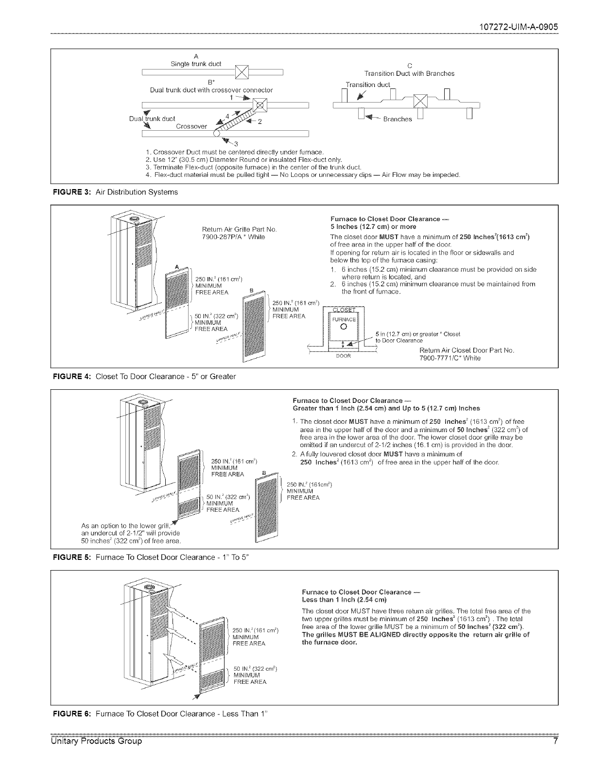
FIGURE 3: Air Distribution Systems
Return Air Grille Part No.
79gg-287P/A * White
250 IN.2 (161 cm 2)
MINIMUM
FREE AREA
50 IN.2 (322 cm 2)
MINIMUM
FREE AREA
Furnace to Closet Door Clearance --
5 Inches (12.7 cm) or more
The closet door MUST have a minimum of 250 Inches2(1613 cm 2)
of free area in the upper half of the doer.
If opening for return air is located in the floor or sidewalls and
below the top of the furnace casing:
1. 6 inches (15,2 cm) minimum clearance must be provided on side
where return is located, and
2. 6 inches (15.2 cm) minimum clearance must be maintMned from
250 IN.2(161 cm2)
>MINIMUM [
FREE AREA
5in(12.7 cm) or greater * Closet
_- to Door CI.......
\ , Return Air Closet Door Part No.
Door 7900--7771/C* White
FIGURE 4: Closet To Door Clearance - 5" or Greater
I FREE AREA
JFREE AREA
As an option to the lower grill,
an undercut of 2-1/2" wilt provide
50 inches 2 (322 cm 2) of flee area.
Furnace to Closet Door Clearance --
Greater than 1 Inch (2.54 cm) and Up to 5 (12.7 cm) Inches
1. "[he closet door MUST have a minimum of 250 Inches 2(1613 cm 2) of flee
area in the upper half of the door and a minimum of 50 Inches 2(322 cm 2) of
free area in the lower area of the door. The tower cIoset door grille may be
omitted if an undercut of 2-1/2 inches (16.1 cm) is provided in the door.
2. AfuHy louvered cIoset door MUST have a minimum of
250 Inches 2(1613 cm 2) of free area in the upper hMf of the door.
_i } 260 IN.2(161cm2)
MINIMUM
FREE AREA
FIGURE 5: Furnace To Closet Door Clearance - 1" To 5"
2501N.2(161 cm 2)
> MINIMUM
FREEAREA
Furnace to Closet Door Clearance --
Less than 1 tnch (2.54 cm}
The closet door MUST have three return air grilles, The total free area of the
two upper gdHes must be minimum of 250 Inches 2 (1613 cm_) ,The total
Freearea of the lower grille MUST be a minimum of 50 tnches 2(322 cm2).
The grilles MUST BE ALIGNED directly opposite the return air grille of
the furnace door.
501N.2(322 cm 2)
MINIMUM
FREE AREA
FIGURE 6: Furnace To Closet Door Clearance - Less Than 1"
Unitary Products Group 7
107272-UIM-A-0905
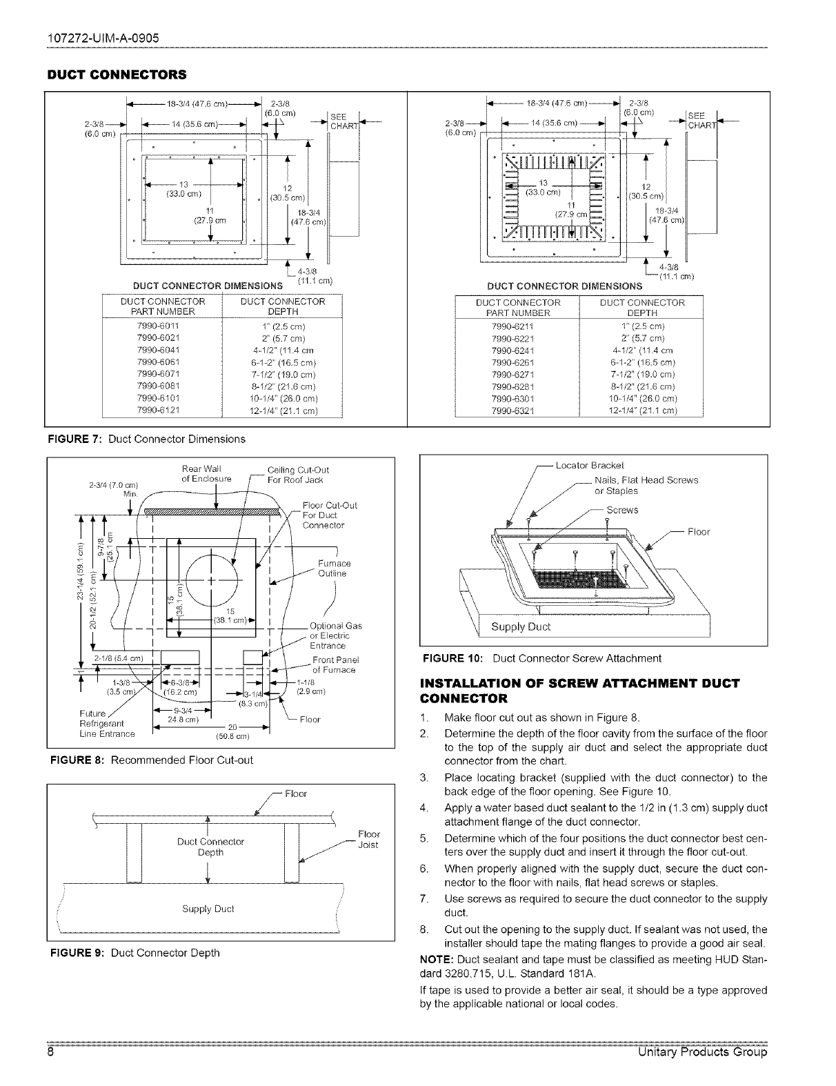
DUCT CONNECTORS
18-3/4 (47.6 cm)------_
2-3/8--
(6.0 cm)
23/8
SEE
4-3/8
(11.1 cm)
DUCT CONNECTOR DIMENSIONS
DUCTCONNECTOR
PAR]NUMBER
7990-6011
7990-6021
7990-6041
7990-6061
7990-6071
7990-6081
7990-6101
7990_6121
DUCT CONNECTOR
DEPTH
1" (2,5 cm)
2" (5.7 cm)
4-1/2" (11.4 cm
6-1-2" (16,5 cm)
7-1/2" (19.0 cm)
8-1/2" (21,6 cm)
10-1/4" (26.0 cm)
12-114" (21.1 cm)
2-3/8---_
(6.0 cm)
DUCT CONNECTOR DIMENSBONS
DUCTCONNECTOR
PAR] NUMBER
7990-6211
7990-6221
7990-6241
7990-6261
7990-6271
7990_6281
7990-6301
7990_6321
43/8
--(11.1 cm)
DUCT CONNECTOR
DEPTH
1" (25 cm)
2" (5.7 cm)
4-1/2" (11.4 cm
6-%2" (16.5 cm)
7-1/2" (19.0 cm)
8-1/2" (21.6 cm)
10-1/4" (26.0 cm)
12-1/4" (21.1 cm}
FIGURE 7: Duct Connector Dimensions
Rear Wall Ceiling Cut-Out
of Enclosure r_ For Roof Jack
2.3/4 (70 cm) I /
Min
; _ F_oor Cut-Out
\/_ For Duct
E I I Connector
_" t) i .. --
t[__ I_1"---/381 ore/*I __ Op_ona_Ga_
/ q I _ I]-- _ or Electric
{ i I _.lJ'l /Entrance
2-1/8 (54 cm) I'_l, Front Pane]
_3/fe_r __ /-_°fFumace
:: _ 1-3/8 -1-1/8
(29 cm)
Future 9-3/4
Refrige_98%4_" -- Floor
Line Entrance (508 cm)
FIGURE 8: Recommended Floor Cut-out
\
t
Duct Connector
Depth
Supply Duct
_€/_- Fioor
Jo_st
i
\
FIGURE 9: Duct Connector Depth
Locator Bracket
__Nails, Fiat Head Screws
"or Staples
Floor
t
Supply Duct
FIGURE 10: Duct Connector Screw Attachment
INSTALLATION OF SCREW ATTACHMENT DUCT
CONNECTOR
1. Make floor cut out as shown in Figure 8.
2. Determine the depth of the floor cavity from the surface of the floor
to the top of the supply air duct and select the appropriate duct
connector from the chart.
3. Place locating bracket (supplied with the duct connector) to the
back edge of the floor opening. See Figure 10.
4. Apply a water based duct sealant to the 1/2 in (1.3 cm) supply duct
attachment flange of the duct connector.
5. Determine which of the four positions the duct connector best cen-
ters over the supply duct and insert it through the floor cut-out.
6. When properly aligned with the supply duct, secure the duct con-
nector to the floor with nails, flat head screws or staples.
7. Use screws as required to secure the duct connector to the supply
duct.
8. Cut out the opening to the supply duct. If sealant was not used, the
installer should tape the mating flanges to provide a good air seal.
NOTE: Duct sealant and tape must be classified as meeting HUD Stan-
dard 3280.715, U.L. Standard 181A.
If tape is used to provide a better air seal, it should be a type approved
by the applicable national or local codes.
8 Unitary Products Group
107272-UIM-A-0905
Locator Bracket
Nails, Flat Head Screws
or Staples
Bend "Tabs Under Duct
Opening to Secure to the
Supply Duct
Floor
Supply Duct
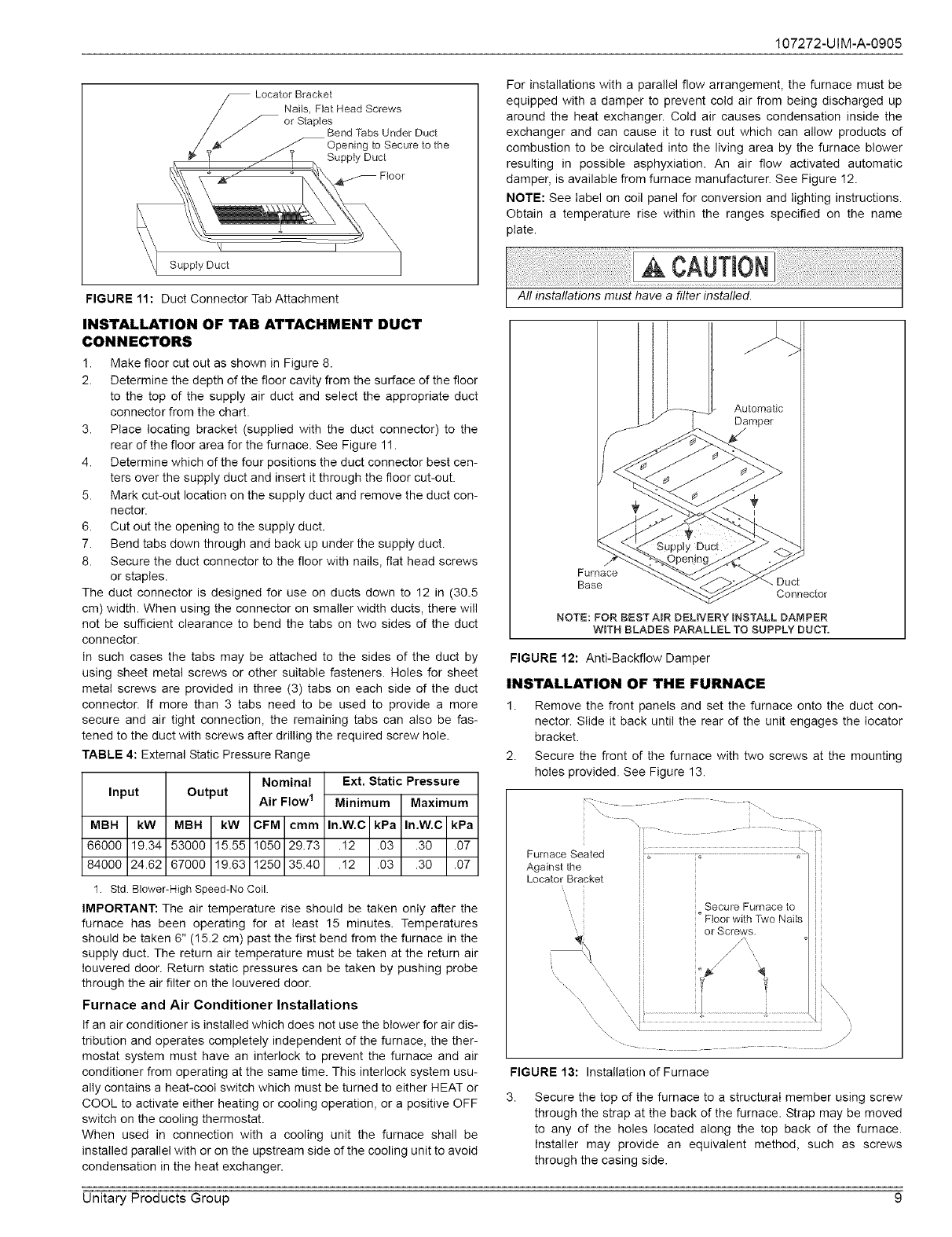
FIGURE 11: Duct Connector Tab Attachment
INSTALLATION OF TAB ATTACHMENT DUCT
CONNECTORS
1. Make floor cut out as shown in Figure 8.
2. Determine the depth of the floor cavity from the surface of the floor
to the top of the supply air duct and select the appropriate duct
connector from the chart.
3. Place locating bracket (supplied with the duct connector) to the
rear of the floor area for the furnace. See Figure 11.
4. Determine which of the four positions the duct connector best cen-
ters over the supply duct and insert it through the floor cut-out.
5. Mark cut-out location on the supply duct and remove the duct con-
nector.
6. Cut out the opening to the supply duct.
7. Bend tabs down through and back up under the supply duct.
8. Secure the duct connector to the floor with nails, fiat head screws
or staples.
The duct connector is designed for use on ducts down to 12 in (30.5
cm) width. When using the connector on smaller width ducts, there will
not be sufficient clearance to bend the tabs on two sides of the duct
connector.
In such cases the tabs may be attached to the sides of the duct by
using sheet metal screws or other suitable fasteners. Holes for sheet
metal screws are provided in three (3) tabs on each side of the duct
connector. If more than 3 tabs need to be used to provide a more
secure and air tight connection, the remaining tabs can also be fas-
tened to the duct with screws after drilling the required screw hole.
TABLE 4: External Static Pressure Range
Input
MBH kW
66000 19.34
84000 24.62
Output
MBH kW
53000 15.55
67000 19.63
Nominal
Air Flow 1
CFM cmm
1050 29.73
1250 35.40
Ext. Static Pressure
Minimum Maximum
In.W.C kPa In.W.C kPa
.!2 .03 .30 .07
.!2 .03 .30 .07
1 Std Blower-High Speed-No Coil.
IMPORTANT: The air temperature rise should be taken only after the
furnace has been operating for at least 15 minutes. Temperatures
should be taken 6" (15.2 cm) past the first bend from the furnace in the
supply duct. The return air temperature must be taken at the return air
Iouvered door. Return static pressures can be taken by pushing probe
through the air filter on the Iouvered door.
Furnace and Air Conditioner Installations
If an air conditioner is installed which does not use the blower for air dis-
tribution and operates completely independent of the furnace, the ther-
mostat system must have an interlock to prevent the furnace and air
conditioner from operating at the same time. This interlock system usu-
ally contains a heat-cool switch which must be turned to either HEAT or
COOL to activate either heating or cooling operation, or a positive OFF
switch on the cooling thermostat.
When used in connection with a cooling unit the furnace shall be
installed parallel with or on the upstream side of the cooling unit to avoid
condensation in the heat exchanger.
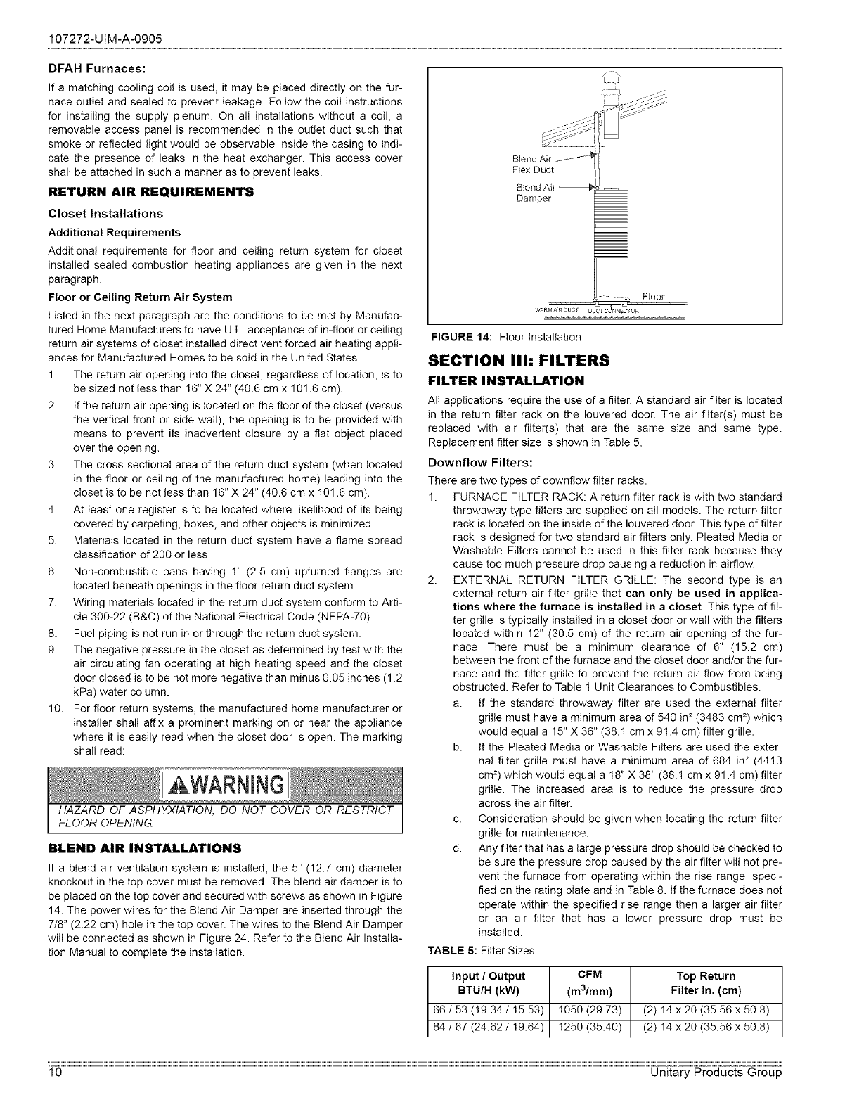
For installations with a parallel flow arrangement, the furnace must be
equipped with a damper to prevent cold air from being discharged up
around the heat exchanger. Cold air causes condensation inside the
exchanger and can cause it to rust out which can allow products of
combustion to be circulated into the living area by the furnace blower
resulting in possible asphyxiation. An air flow activated automatic
damper, is available from furnace manufacturer. See Figure 12.
NOTE: See label on coil panel for conversion and lighting instructions.
Obtain a temperature rise within the ranges specified on the name
plate.
Furnace
Base
Conneo[or
NOTE: FOR BEST AIR DELIVERY INSTALL DAMPER
WiTH BLADES PARALLEL TO SUPPLY DUCT,
FIGURE 12: Anti-Backfiow Damper
INSTALLATION OF THE FURNACE
1. Remove the front panels and set the furnace onto the duct con-
nector. Slide it back until the rear of the unit engages the Iocator
bracket.
2. Secure the front of the furnace with two screws at the mounting
holes provided. See Figure 13.
\ _
Furnace Seated
Againstthe
Locator Bracket
Secure Furnace to
° Floor with Two NaiIs
or Screws.
%
V
FIGURE 13: Installation of Furnace
3. Secure the top of the furnace to a structural member using screw
through the strap at the back of the furnace. Strap may be moved
to any of the holes located along the top back of the furnace.
Installer may provide an equivalent method, such as screws
through the casing side.
Unitary Products Group 9
107272-UIM-A-0905
DFAH Furnaces:
If a matching cooling coil is used, it may be placed directly on the fur-
nace outlet and sealed to prevent leakage. Follow the coil instructions
for installing the supply plenum. On all installations without a coil, a
removable access panel is recommended in the outlet duct such that
smoke or reflected light would be observable inside the casing to indi-
cate the presence of leaks in the heat exchanger. This access cover
shall be attached in such a manner as to prevent leaks.
RETURN AIR REQUIREMENTS
Closet Installations
Additional Requirements
Additional requirements for floor and ceiling return system for closet
installed sealed combustion heating appliances are given in the next
paragraph.
Floor or Ceiling Return Air System
Listed in the next paragraph are the conditions to be met by Manufac-
tured Home Manufacturers to have U.L. acceptance of in-floor or ceiling
return air systems of closet installed direct vent forced air heating appli-
ances for Manufactured Homes to be sold in the United States.
1. The return air opening into the closet, regardless of location, is to
be sized not less than !6" X 24" (40.6 cm x 101.6 cm).
2. If the return air opening is located on the floor of the closet (versus
the vertical front or side wall), the opening is to be provided with
means to prevent its inadvertent closure by a flat object placed
over the opening.
3. The cross sectional area of the return duct system (when located
in the floor or ceiling of the manufactured home) leading into the
closet is to be not less than 16" X 24" (40.6 cm x 101.6 cm).
4. At least one register is to be located where likelihood of its being
covered by carpeting, boxes, and other objects is minimized.
5. Materials located in the return duct system have a flame spread
classification of 200 or less.
6. Non-combustible pans having 1" (2.5 cm) upturned flanges are
located beneath openings in the floor return duct system.
7. Wiring materials located in the return duct system conform to Arti-
cle 300-22 (B&C) of the National Electrical Code (NFPA-70).
8. Fuel piping is not run in or through the return duct system.
9. The negative pressure in the closet as determined by test with the
air circulating fan operating at high heating speed and the closet
door closed is to be not more negative than minus 0.05 inches (1.2
kPa) water column.
10. For floor return systems, the manufactured home manufacturer or
installer shall affix a prominent marking on or near the appliance
where it is easily read when the closet door is open. The marking
shall read:
HAZARD OF ASPHYXIATION, DO NOT COVER OR RESTRICT
FLOOR OPENING
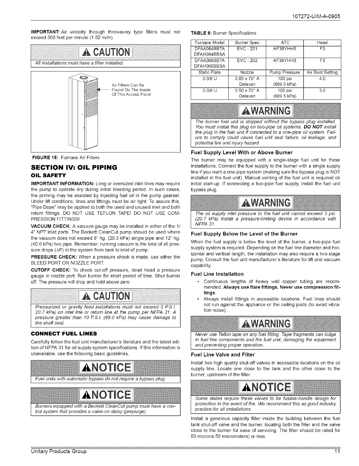
BLEND AIR INSTALLATIONS
If a blend air ventilation system is installed, the 5" (12.7 cm) diameter
knockout in the top cover must be removed. The blend air damper is to
be placed on the top cover and secured with screws as shown in Figure
14. The power wires for the Blend Air Damper are inserted through the
7/8" (2.22 cm) hole in the top cover. The wires to the Blend Air Damper
will be connected as shown in Figure 24. Refer to the Blend Air Installa-
tion Manual to complete the installation.
f ,
Flex Duct
Damper
Floor
WARM_R_UCl pKCl c:! t!_r:_g _ ........................
FIGURE 14: Floor Installation
SECTION IIh FILTERS
FILTER INSTALLATION
All applications require the use of a filter. A standard air filter is located
in the return filter rack on the Iouvered door. The air filter(s) must be
replaced with air filter(s) that are the same size and same type.
Replacement filter size is shown in Table 5.
Downflow Filters:
There are two types of dewnflow filter racks.
1. FURNACE FILTER RACK: A return filter rack is with two standard
throwaway type filters are supplied on all models. The return filter
rack is located on the inside of the leuvered door. This type of filter
rack is designed for two standard air filters only. Pleated Media or
Washable Filters cannot be used in this filter rack because they
cause too much pressure drop causing a reduction in airflow.
2. EXTERNAL RETURN FILTER GRILLE: The second type is an
external return air filter grille that can only be used in applica-
tions where the furnace is installed in a closet. This type of fil-
ter grille is typically installed in a closet door or wall with the filters
located within 12" (30.5 cm) of the return air opening of the fur-
nace. There must be a minimum clearance of 6" (15.2 cm)
between the front of the furnace and the closet door and/or the fur-
nace and the filter grille to prevent the return air flow from being
obstructed. Refer to Table 1 Unit Clearances to Combustibles.
a. If the standard throwaway filter are used the external filter
grille must have a minimum area of 540 in2 (3483 cm 2) which
would equal a 15" X 36" (38.! cm x 91.4 cm) filter grille.
b. If the Pleated Media or Washable Filters are used the exter-
nal filter grille must have a minimum area of 684 in= (4413
cm=) which would equal a 18" X 38" (38.1 cm x 91.4 cm) filter
grille. The increased area is to reduce the pressure drop
across the air filter.
c. Consideration should be given when locating the return filter
grille for maintenance.
d. Any filter that has a large pressure drop should be checked to
be sure the pressure drop caused by the air filter will not pre-
vent the furnace from operating within the rise range, speci-
fied on the rating plate and in Table 8. If the furnace does not
operate within the specified rise range then a larger air filter
or an air filter that has a lower pressure drop must be
installed.
TABLE 5: Filter Sizes
Input /Output CFM Top Return
BTU/H (kW) (m3/mm) Filter In. (cm)
66/53(19.34/15.53) !050(29.73) (2) 14 x 20 (35.56 x 50.8)
64/67(24.62/19.64) 1250(35.40) (2) 14 x 20 (35.56 x 50.6)
10 Unitary Products Group
107272-UIM-A-0905
IMPORTANT: Air velocity through throwaway type filters must not
exceed 300 feet per minute (1.52 m/m).
Air Filters Can Be
Found On The Inside
Of This Access Panel
FIGURE 15: Furnace Air Filters
SECTION IV: OIL PIPING
OIL SAFETY
IMPORTANT INFORMATION: Long or oversized inlet lines may require
the pump to operate dry during initial bleeding period. In such cases,
the priming may be assisted by injecting fuel oil in the pump gearset.
Under lift conditions, lines and fittings must be air tight. To assure this,
"Pipe Dope" may be applied to both the used and unused inlet and both
return fittings. DO NOT USE TEFLON TAPE! DO NOT USE COM-
PRESSION FITTINGS!
VACUUM CHECK: A vacuum gauge may be installed in either of the 1/
4" NPT inlet ports. The Beckett CleanCut pump should be used where
the vacuum does not exceed 6" hg. (20.3 kPa) single pipe and 12" hg.
(40.6 kPa) two pipe. Remember, running vacuum is the total of all pres-
sure drops (AP) in the system from tank to inlet of pump.
PRESSURE CHECK: When a pressure check is made, use either the
BLEED PORT OR NOZZLE PORT.
CUTOFF CHECK: To check cut-off pressure, dead head a pressure
gauge in nozzle port. Run burner for short period of time. Shut burner
off. The pressure will drop and hold above zero
TABLE 6: Burner Specifications
Furnace Model Burner Spec ATC Head
DFAA084BBTA EVC - 201 AF36YHHS F3
DFAH084BBSA
DFAA066BBTA EVC - 202 AF36YHHS F3
DFAH066BBSA
Static Plate Nozzle Pump Pressure Air Boot Setting
3-318 U 0.65 x 70 ° A 100 psi 4.0
Delavan (689.5 kPa)
3-318 U 0.50 x 70 ° A 100 psi 3.0
Delavan (689.5 kPa)
The burner fuel unit is shipped without the bypass plug installed.
You must install this plug on two-pipe oi! systems. DO NOT install
the plug in the fuel unit if connected to a one-pipe oil system. Fail-
ure to comply could cause fuel unit seal failure, oil leakage, and
potential fire and injury hazard.
Fuel Supply Level With or Above Burner
The burner may be equipped with a single-stage fuel unit for these
installations. Connect the fuel supply to the burner with a single supply
line if you want a one-pipe system (making sure the bypass plug is NOT
installed in the fuel unit). Manual venting of the fuel unit is required on
initial start-up. If connecting a two-pipe fuel supply, install the fuel unit
bypass plug.
The oil supply inlet pressure to the fuel unit cannot exceed 3 psi.
(20.7 kPa) Instafl a pressure-limiting device in accordance with
NFPA 31.
Fuel Supply Below the Level of the Burner
When the fuel supply is below the level of the burner, a two-pipe fuel
supply system is required. Depending on the fuel line diameter and hor-
izontal and vertical length, the installation may also require a two-stage
pump. Consult the fuel unit manufacturer's literature for lift and vacuum
capability.
Fuel Line Installation
• Continuous lengths of heavy wall copper tubing are recom-
mended. Always use flare fittings, Never use compression fit-
tings.
• Always install fittings in accessible locations. Fuel lines should
not run against the appliance or the ceiling joists (to avoid vibra-
tion noise).
CONNECT FUEL LINES
Carefully follow the fuel unit manufacturer's literature and the latest edi-
tion of NFPA 31 for oil supply system specifications. If this information is
unavailable, use the following basic guidelines.
Fuel units with automatic bypass do not require a bypass plug.
Never use Teflon tape on any fue! fitting. Tape fragments can lodge
in fue! line components and the fuel unit, damaging the equipment
and preventing proper operation.
Fuel Line Valve and Filter
Install two high quality shut-off valves in accessible locations on the oil
supply line. Locate one close to the tank and the other close to the
burner, upstream of the filter.
Burners equipped with a Beckett CleanCut pump must have a con-
trol system that provides a valve-on delay (prepurge).
Some states require these valves to be fusible-handle design for
protection in the event of fire. We recommend this as good industry
practice for all installations.
Install a generous capacity filter inside the building between the fuel
tank shut-off valve and the burner, locating both the filter and the valve
close to the burner for ease of servicing. The filter should be rated for
50 microns 50 micrometers) or less.
Unitary Products Group 11
107272-UIM-A-0905
NOTICE SPECIAL REQUIREMENTS
This equipment must be installed, adjusted, and started only by a
qualified service technician, an individual or agency, licensed and
experienced with al! codes and ordinances, who is responsible for
the installation and adjustment of the equipment. The installation
must comply with all local codes and ordinances and with the
National Fire Protection Standard for Liquid Fuel Equipment, NFPA
3! (or in Canada the installation must comply with CSA B139-M91).
DANGER
This fumace is designed to operate on #! FUEL-OIL or #2 FUEL-
OIL ONLX Do Not burn any other fue! in this furnace. Burning any
fue! except #1 FUEL-OIL or #2 FUEL-OIL in this furnace can cause
premature heat exchanger burnout, high levels of carbon monox-
ide, excessive sooting, a fire hazard, personal injury, property dam-
age, and/or death.
In Canada, the furnace is designed to operate on #1 STOVE OIL or
#2 FURNACE OIL ONLY
THE EFFECT OF ELEVATION ON OIL BURNER
FIRING
The elevation of the installation of a modern high-speed flame retention
oil burner affects the performance of the burner, Allowance for elevation
must be taken into consideration when choosing an oil burner and oper-
ating it above 2000 ft. (6!0m).
It is especially important in high elevation installations to adjust air set-
tings to match the burner nozzle firing rate. As elevation increases
above sea level, the ambient air contains less oxygen. Because there is
less available oxygen per cubic foot of air, the burner must deliver a
greater volume flew (cfm) of air to provide the proper amount of oxygen
for the amount of oil being burned, This is the reason that an increase in
the burner air setting may be required.
It is also important in high elevation installations to consider the maxi-
mum firing rate of the burner, so that the heat input as required by the
application is maintained. Regardless of elevation, the oil burner has a
maximum volume flow of air that it can deliver, As a result, the maxi-
mum firing rate of the oil burner decreases as the elevation increases,
because the combustion air contains less oxygen, An increase in the
size of a fixed-type retention head, or even the use of an oil burner with
a higher maximum firing rate may be necessary.
The effect of elevation up to 2000 ft. (610 m) is minimal, so no re-rate is
necessary up to 2000 ft. (610 m) elevation. Above 2000 ft. (610 m), for
every 1000 ft. (305 m) above sea level (including the first 2000 ft. (610
m), there is a 1.84% rate reduction of the burner. To assist you, we have
included the following chart and some examples: Refer to Table 7,
DANGER
The pressure regulator on the fuel pump must not be adjusted in
excess of 100 PSIG (689 kPa).
Pressures exceeding 100 PSIG (689 kPa) may cause an overheat-
ing condition which can lead to premature heat exchanger failure,
resulting in a fire or explosion, or cause damage to the furnace of
some of its components that will result in property damage and loss
of life. Refer to Figure 16 for Pressure Regulator Location.
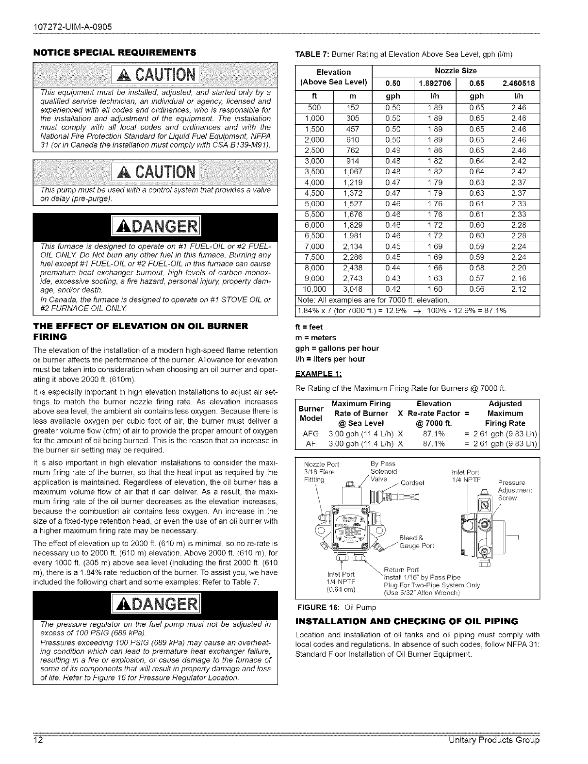
TABLE 7: Burner Rating at Elevation Above Sea Level, gph (t/m)
Elevation
(Above Sea Level)
ft m
500 !52
1,000 305
1,500 457
2,000 610
2,500 762
3,000 914
3,500 1,067
4,000 1,2!9
4,500 1,372
5,000 1,527
5,500 1,676
6,000 1,829
6,500 1,981
7,000 2,134
7,500 2,286
8,000 2,438
9,000 2,743
10,000 3,048
Nozzle Size
0.60 1.892706 0.66
gph I/h gph
0.50 ! .89 0.65
0.50 ! .89 0.65
0.50 1.89 0.65
0.50 1.89 0.65
0.49 ! .86 0.65
0.48 1.82 0.64
0.48 ! .82 0.64
0.47 1.79 0.63
0.47 1.79 0.63
0.46 ! .76 0.61
0.46 ! .76 0.61
0.46 ! .72 0.60
0.46 ! .72 0.60
0.45 ! .69 0.59
0.45 1.69 0.59
0.44 ! .66 0.58
0.43 1.63 0.57
0.42 1.60 0.56
2.460618
I/h
2.46
2.46
2.46
2.46
2.46
2.42
2.42
2.37
2.37
2.33
2.33
2.28
2.28
2.24
2.24
2.20
2.16
2.12
Note: All examples are for 7000 ft. elevation.
1.84% x 7 (for 7000 ft.) =12.9% > 100%- 12.9% =87.1%
ft = feet
m= meters
gph = gallons per hour
I/h = liters per hour
Re-Rating of the Ma×imum Firing Rate for Burners @ 7000 ft.
Maximum Firing Elevation Adjusted I
Burner
Model Rate of Burner X Re-rate Factor = Maximum I
@ Sea Level @ 7000 ft. Firing Rate I
AFG 3.00 gph (11.4 L/h) X 87.1% 2.61 gph (9.83 Lh)
AF 3.00 gph (1! .4 L/h) X 87.1% 2.61 gph (9.83 Lh)
Nozzle Port By Pass
3/16 Flare Solenoid Inlet Port
Pressure
Adjustment
Screw
1/4 NPTF Ptug ForTwo-Pipe System Only
(0.64 cm) (Use 5/32"Allen Wrench)
FIGURE 16: Oil Pump
INSTALLATION AND CHECKING OF OIL PIPING
Location and installation of oil tanks and oil piping must comply with
local codes and regulations. In absence of such codes, follow NFPA 31 :
Standard Floor Installation of Oil Burner Equipment,
12 Unitary Products Group
107272-UIM-A-0905
Follow information provided with the burner, the fuel pump, or the calcu-
lation below to determine pipe size and length.
L = Line Length in feet
H = Head in feet
Q = Firing rate in GPH
3/8" (0.95 cm) line L = (6 - 0.75 x H) /0.0086 x Q)
1/2" (1.27 cm) line L = (6- 0.75 x H) /(0.00218 x Q)
If tank is above the oil pump, then use the following calculation:
3/8" (0.95 cm) line L = (6 + 0.75 x H) /(0.0086 x Q)
1/2" (1.27 cm) line L = (6 + 0.75 x H) /(0.00218 x Q)
IMPORTANT: The recommended piping configuration is a single or two
pipe system that is inserted into the top of the tank as shown in Figure
17 or 18. The two pipe system should be used in applications where the
oil tank is considerably lower than the burner and the oil pump keeps
losing its prime. The oil line should never be connected to the bottom of
the oil tank if the oil tank is outdoors. Water in the bottom of the oil will
freeze in the winter causing the oil line to freeze.
ONE PIPE SYSTEM
DO NOT INSTALL BY-PASS PLUG! Connect inlet line to pump inlet.
Start burner. Arrange primary burner control for continuous operation
during the purging. Place a clear plastic tube on bleed valve. Open
bleed valve ! turn counterclock wise. Bleed until all air bubbles disap-
pear. Tighten bleed valve securely. Hurried bleeding will impair efficient
operation of unit. Refer to Figures 16 & 17.
Air [q L=H+R
Ven[ _ FuetUnit
n
----tt-%
FIGURE 17: One-Pipe System
TWO PIPE SYSTEM
Remove 1/16" (0.16 cm) pipe by-pass plug from plastic bag attached to
the unit. Remove 1/4" (0.635 cm) plug from return port. Insert by-pass
plug into the return port of the oil pump. The oil pump return port loca-
tion is shown in Figure 16.
Insert a 1/4" MPT x flare adaptor into the by-pass port and the inlet port.
Attach the return and inlet copper lines that go to the oil tank. Start the
burner. DO NOT open the bleed valve. The air in the oil lines will bleed
automatically.
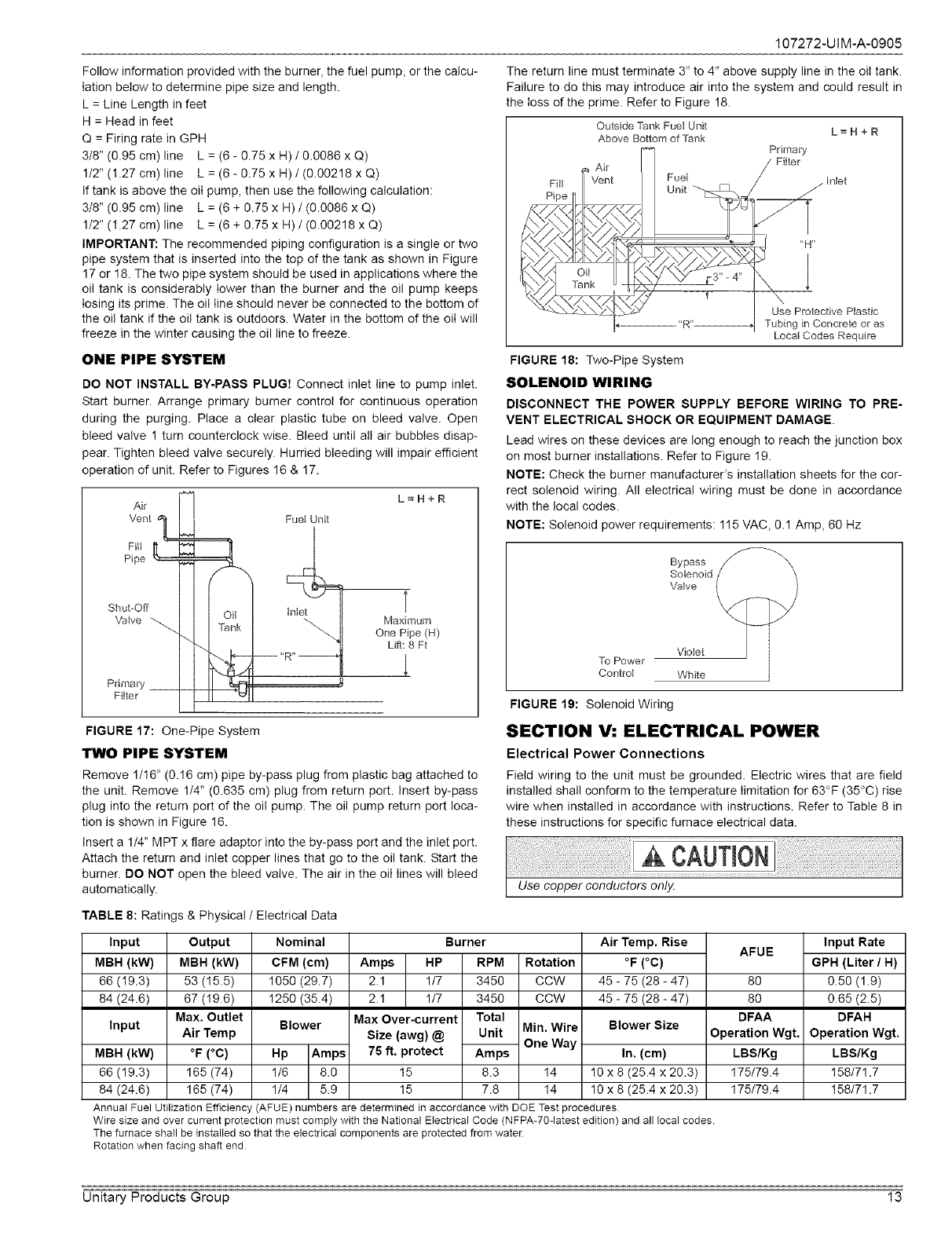
The return line must terminate 3" to 4" above supply line in the oil tank.
Failure to do this may introduce air into the system and could result in
the loss of the prime. Refer to Figure !8.
Outside Tank Fuel Unit
Above Bottom of "Tank L=H+R
Primary
'Filter
_ Inlet
"H"
1
Use Protective Ptastic
Tubing in Concrete or as
LocatCodes Require
FIGURE 18: Two-Pipe System
SOLENOID WIRING
DISCONNECT THE POWER SUPPLY BEFORE WIRING TO PRE-
VENT ELECTRICAL SHOCK OR EQUIPMENT DAMAGE.
Lead wires on these devices are long enough to reach the junction box
on most burner installations. Refer to Figure 19.
NOTE: Check the burner manufacturer's installation sheets for the cor-
rect solenoid wiring. All electrical wiring must be done in accordance
with the local codes.
NOTE: Solenoid power requirements: 1!5 VAC, 0.1 Amp, 60 Hz
To Power
Control
Bypass _
Vioiet J ]
White
FIGURE 19: Solenoid Wiring
SECTION V: ELECTRICAL POWER
Electrical Power Connections
Field wiring to the unit must be grounded. Electric wires that are field
installed shall conform to the temperature limitation for 63°F (35°C) rise
wire when installed in accordance with instructions. Refer to Table 8 in
these instructions for specific furnace electrical data.
TABLE 8: Ratings & Physical /Electrical Data
Input
MBH (kW)
66 (19.3)
84 (24.6)
Input
MBH (kW)
66 (19.3)
84 (24.6)
Output
MBH (kW)
53 (15.5)
67 (19.6)
Max, Outlet
Air Temp
°F (°C)
165 (74)
165 (74)
Nominal
CFM (cm)
1050 (29.7)
1250 (35.4)
Blower
Hp Amps
1/6 8.0
1/4 5.9
Burner Air Temp. Rise
Ampe HP RPM Rotation °F (°C)
2.1 1/7 3450 CCW 45 - 75 (28 - 47)
2.1 1/7 3450 CCW 45 - 75 (28 - 47)
Max Over-current Total
Size (awg) @ Unit Min. Wire Blower Size
One Way
75 ft. protect Ampe In. (cm)
15 8.3 14 10 x 8 (25.4 x 20.3)
15 7.8 14 10 x 8 (25.4 x 20.3)
AFUE
8O
8O
DFAA
Operation Wgt.
LBS/Kg
175/79.4
175/79.4
Input Rate
GPH (Liter /H)
0.50 (1.9)
0.65 (2.5)
DFAH
Operation Wgt.
LBS/Kg
158/71.7
!58/71.7
Annual Fuel Utilization Efficiency (AFUE) numbers are determined in accordance with DOE Test procedures
Wire size and over current protection must comply with the National Electrical Code (NFPA-70-1atest edition) and all local codes.
The furnace shall be installed so that the electrical components are protected from water
Rotation when facing shaft end
Unitary Products Group 13
107272-UIM-A-0905
NOTE: A burner with an electronic igniter or a PSC motor will have a
lower operating current. The actual load should be determined by a cur-
rent meter.
NOTE: See appliance manufacturer's burner specifications for required
outlet pressure. Pressure is !00 psig (689 kPa) unless otherwise noted.
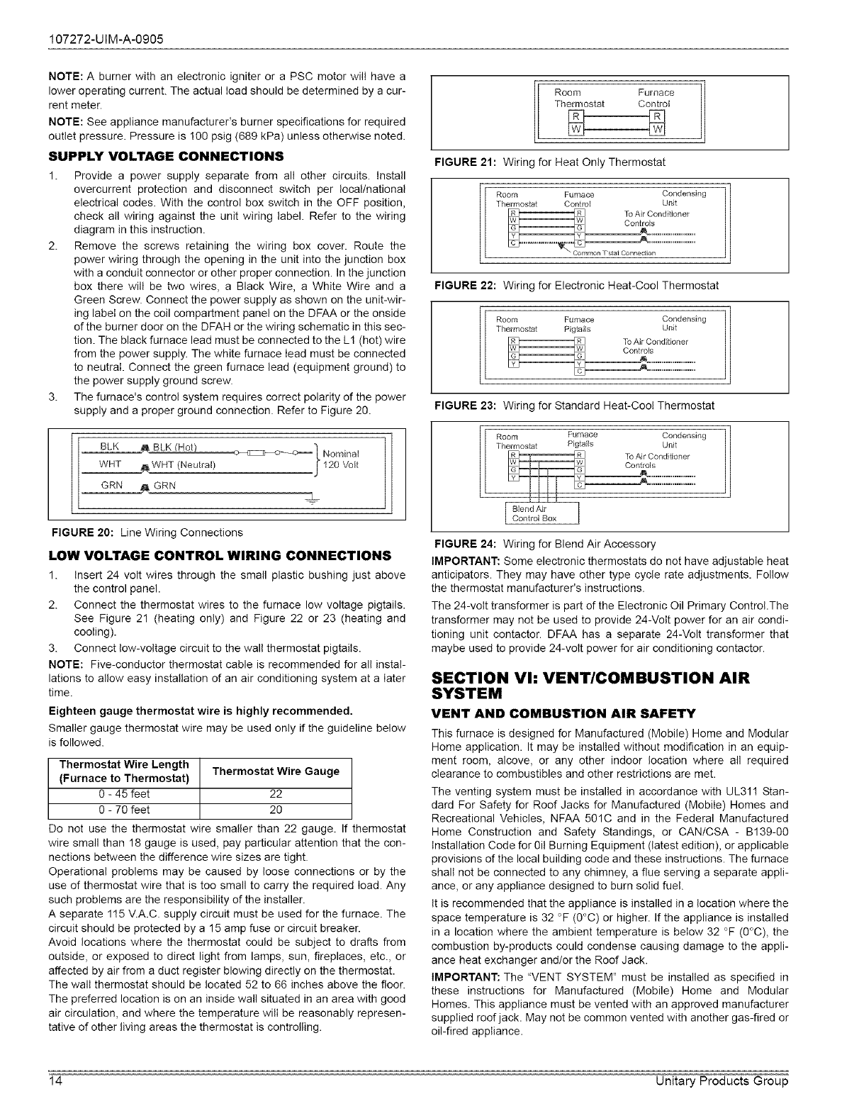
SUPPLY VOLTAGE CONNECTIONS
1. Provide a power supply separate from all other circuits. Install
overcurrent protection and disconnect switch per local/national
electrical codes. With the control box switch in the OFF position,
check all wiring against the unit wiring label. Refer to the wiring
diagram in this instruction.
2. Remove the screws retaining the wiring box cover. Route the
power wiring through the opening in the unit into the junction box
with a conduit connector or other proper connection. In the junction
box there will be two wires, a Black Wire, a White Wire and a
Green Screw. Connect the power supply as shown on the unit-wir-
ing label on the coil compartment panel on the DFAA or the onside
of the burner door on the DFAH or the wiring schematic in this sec-
tion. The black furnace lead must be connected to the L1 (hot) wire
from the power supply. The white furnace lead must be connected
to neutral. Connect the green furnace lead (equipment ground) to
the power supply ground screw.
3. The furnace's control system requires correct polarity of the power
supply and a proper ground connection. Refer to Figure 20.
Nominal
120 Volt
FIGURE 20: Line Wiring Connections
LOW VOLTAGE CONTROL WIRING CONNECTIONS
1. Insert 24 volt wires through the small plastic bushing just above
the control panel.
2. Connect the thermostat wires to the furnace low voltage pigtails.
See Figure 21 (heating only) and Figure 22 or 23 (heating and
cooling).
3. Connect low-voltage circuit to the wall thermostat pigtails.
NOTE: Five-conductor thermostat cable is recommended for all instal-
lations to allow easy installation of an air conditioning system at a later
time.
Eighteen gauge thermostat wire is highly recommended,
Smaller gauge thermostat wire may be used only if the guideline below
is followed.
Thermostat Wire Length
(Furnace to Thermostat) Thermostat Wire Gauge
0 - 45 feet 22
O - 70 feet 20
Do not use the thermostat wire smaller than 22 gauge. If thermostat
wire small than 18 gauge is used, pay particular attention that the con-
nections between the difference wire sizes are tight.
Operational problems may be caused by loose connections or by the
use of thermostat wire that is too small to carry the required load. Any
such problems are the responsibility of the installer.
A separate 115 V.A.C. supply circuit must be used for the furnace. The
circuit should be protected by a 15 amp fuse or circuit breaker.
Avoid locations where the thermostat could be subject to drafts from
outside, or exposed to direct light from lamps, sun, fireplaces, etc., or
affected by air from a duct register blowing directly on the thermostat.
The walI thermostat should be located 52 to 66 inches above the floor.
The preferred location is on an inside wall situated in an area with good
air circulation, and where the temperature will be reasonably represen-
tative of other living areas the thermostat is controlling.
Room Furnace
Thermosta[ Con[rot
FIGURE 21: Wiring for Heat Only Thermostat
Room Furnace Condensing
Thermostat Control Unit 11
FIGURE 22: Wiring for Electronic Heat-Cool Thermostat
Room Furnace Condensing
Thermostat Pigtails Unit 11
FIGURE 23: Wiring for Standard Heat-Coo! Thermostat 11
l Blend Air IControl Box
FIGURE 24: Wiring for Blend Air Accessory
IMPORTANT: Some electronic thermostats do not have adjustable heat
anticipators. They may have other type cycle rate adjustments. Follow
the thermostat manufacturer's instructions.
The 24-volt transformer is part of the Electronic Oil Primary Control.The
transformer may not be used to provide 24-Volt power for an air condi-
tioning unit contactor. DFAA has a separate 24-Volt transformer that
maybe used to provide 24-volt power for air conditioning contactor.
SECTION Vh VENT/COMBUSTION AIR
SYSTEM
VENT AND COMBUSTION AIR SAFETY
This furnace is designed for Manufactured (Mobile) Home and Modular
Home application. It may be installed without modification in an equip-
ment room, alcove, or any other indoor location where all required
clearance to combustibles and other restrictions are met.
The venting system must be installed in accordance with UL311 Stan-
dard For Safety for Roof Jacks for Manufactured (Mobile) Homes and
Recreational Vehicles, NFAA 501C and in the Federal Manufactured
Home Construction and Safety Standings, or CANICSA - B139-00
Installation Code for 0il Burning Equipment (latest edition), or applicable
provisions of the local building code and these instructions. The furnace
shall not be connected to any chimney, a flue serving a separate appli-
ance, or any appliance designed to burn solid fuel.
It is recommended that the appliance is installed in a location where the
space temperature is 32 °F (0°C) or higher. If the appliance is installed
in a location where the ambient temperature is below 32 °F (0°C), the
combustion by-products could condense causing damage to the appli-
ance heat exchanger and/or the Roof Jack.
IMPORTANT: The "VENT SYSTEM" must be installed as specified in
these instructions for Manufactured (Mobile) Home and Modular
Homes. This appliance must be vented with an approved manufacturer
supplied roof jack. May not be common vented with another gas-fired or
oil-fired appliance.
14 Unitary Products Group
107272-UIM-A-0905
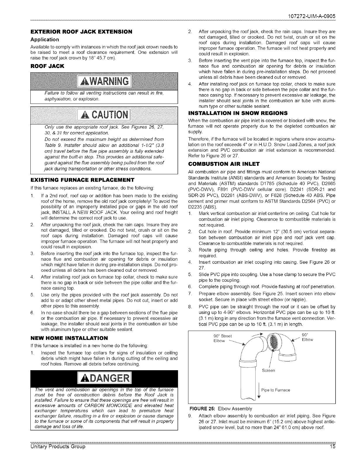
EXTERIOR ROOF JACK EXTENSION
Application
Available to comply with instances in which the roof jack crown needs to
be raised to meet a roof clearance requirement. One extension will
raise the roof jack crown by 18" 45.7 cm).
ROOF JACK
Failure to follow aft venting instructions can result in fire,
asphyxiation, or explosion.
Only use the appropriate roof jack. See Figures 26, 27,
30, & 31 for correct application.
Do not exceed the maximum height as determined from
Table 9. Installer should allow an additional 1-1/2" (3.8
cm) travel before the flue pipe assembly is fully extended
against the built-in stop. This provides an additional safe-
guard against the flue assembly being pulled from the roof
jack during transportation or other stress conditions.
EXISTING FURNACE REPLACEMENT
If this furnace replaces an existing furnace, do the following:
1. If a 2nd roof, roof cap or addition has been made to the existing
roof of the home, remove the old roof jack completely! To avoid the
possibility of an improperly installed pipe or gaps in the old roof
jack, INSTALL A NEW ROOF JACK. Your ceiling and roof height
will determine the correct roof jack to use.
2. After unpacking the roof jack, check the rain caps. Insure they are
not damaged, tilted or crooked. Do not twist, crush or sit on the
roof caps during installation. Damaged roof caps will cause
improper furnace operation. The furnace will not heat properly and
could result in explosion.
3. Before inserting the roof jack into the furnace top, inspect the fur-
nace flue and combustion air opening for debris or insulation
which might have fallen in during pre-installation steps. Do not pro-
ceed unless all debris has been cleaned out or removed.
4. After installing roof jack on furnace top collar, check to make sure
there is no gap in back or side between the pipe collar and the fur-
nace casing top.
5. Use only the pipes provided with the roof jack assembly. Do not
add to or adapt other sheet metal pipes. Do not cut, insert or add
other pipes to this assembly.
6. In no case should there be a gap between sections of the flue pipe
or the combustion air pipe. If necessary to prevent excessive air
leakage, the installer should seal joints in the combustion air tube
with aluminum type or other suitable sealant.
NEW HOME INSTALLATION
If this furnace is installed in a new home do the following:
1. Inspect the furnace top collars for signs of insulation or ceiling
debris which might have fallen in during cutting of the ceiling and
roof holes. Remove all debris before continuing.
The vent and combustion air openings in the top of the furnace
must be free of construction debris before the Roof Jack is
installed. Failure to ensure that these openings are free will result in
excessive amounts of CARBON MONOXIDE and elevated heat
exchanger temperatures which can lead to premature heat
exchanger failure, resulting in a fire or explosion or cause damage
to the furnace or some of its components that will result in property
damage and loss of life.
2. After unpacking the roof jack, check the rain caps. Insure they are
not damaged, tilted or crooked. Do not twist, crush or sit on the
roof caps during installation. Damaged roof caps will cause
improper furnace operation. The furnace will not heat properly and
could result in explosion.
3. Before inserting the vent pipe into the furnace top, inspect the fur-
nace flue and combustion air opening for debris or insulation
which have fallen in during pre-installation steps. Do not proceed
unless all debris have been cleaned out or removed.
4. After installing roof jack on furnace top collar, check to make sure
there is no gap in back or side between the pipe collar and the fur-
nace casing top. If necessary to prevent excessive air leakage, the
installer should seal joints in the combustion air tube with alumi-
num type or other suitable sealant.
INSTALLATION IN SNOW REGIONS
When the combustion air pipe inlet is covered or blocked with snow, the
furnace will not operate properly due to the depleted combustion air
supply.
Therefore, if the furnace will be located in regions where snow accumu-
lation on the roof exceeds 4" or in H.U.D. Snow Load Zones, a roof jack
extension and PVC combustion air inlet extension is recommended.
Refer to Figure 26 or 27.
COMBUSTION AIR INLET
All combustion air pipe and fittings must conform to American National
Standards Institute (ANSI) standards and American Society for Testing
and Materials (ASTM) standards D1785 (Schedule 40 PVC), D2665
(PVC-DWV), F891 (PVC-DWV cellular core). D2241 (SDR-21 and
SDR-26 PVC), D2261 (ABS-DWV), or F628 (Schedule 40 ABS. Pipe
cement and primer must conform to ASTM Standards D2564 (PVC) or
D2235 (ABS).
1. Mark vertical combustion air inlet centerline on ceiling. Cut hole for
combustion air inlet piping. Clearance to combustible materials is
not required.
2. Cut hole in roof. Provide minimum 12" (30.5 cm) vertical separa-
tion between combustion air inlet pipe and roof jack vent cap.
Clearance to combustible materials is not required.
3. Route piping through ceiling and holes. Provide firestop as
required.
4. Insert combustion air inlet coupling into casing. See Figure 26 or
27.
5. Slide PVC pipe into coupling. Use a hose clamp to secure the PVC
pipe to the coupling.
6. Complete piping through roof. Provide flashing at roof penetration.
7. Prepare elbow assembly. See Figure 25. Insert screen into elbow
socket. Secure in place with street elbow (or nipple).
8. PVC pipe can be straight through the roof or it can be offset by
using up to 4-90 ° elbows. Horizontal PVC pipe can be up to !0 ft.
(3.1 m) long in any direction from the furnace vent connection. Ver-
tical PVC pipe can be up to !0 ft. (3.! m) in length.
90 _'Street
Elbow
Screen
Pipe to Furnace
FIGURE 25: Elbow Assembly
9. Attach elbow assembly to combustion air inlet piping. See Figure
26 or 27. Inlet must be minimum 6" (15.2 cm) above highest antic-
ipated snow level, but no more than 24" 61.0 cm) above roof.
Unitary Products Group 15
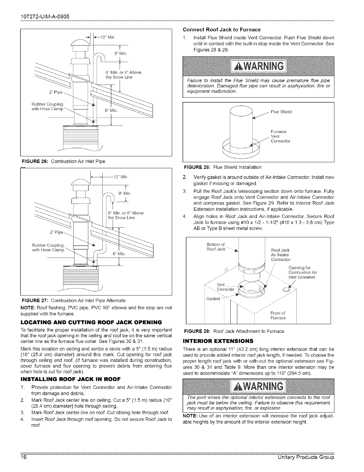
107272-UIM-A-0905
Min.
T
9" Min.
2" Pipe
Rubber Coupling
with Hose Ctamp
6" Min, or 6" Above
the Snow Line
6" Min,
FIGURE 26: Combustion Air Inlet Pipe
2" Pi
Rubber Coupling
with Hose Clan"
t
9" Min.
6" Min, or 6" Above
the Snow Line
FIGURE 27: Combustion Air Inlet Pipe Alternate
NOTE: Roof flashing, PVC pipe, PVC 90 ° elbows and fire stop are not
supplied with the furnace.
LOCATING AND CUTTING ROOF JACK OPENING
To facilitate the proper installation of the roof jack, it is very important
that the roof jack opening in the ceiling and roof be on the same vertical
center line as the furnace flue collar. See Figures 30 & 3!.
Mark this location on ceiling and scribe a circle with a 5" (1.5 m) radius
{10" (25.4 cm) diameter} around this mark. Cut opening for roof jack
through ceiling and roof. (if furnace was installed during construction,
cover furnace and flue opening to prevent debris from entering flue
when hole is cut for roof jack).
INSTALLING ROOF JACK IN ROOF
1. Provide protection for Vent Connector and Air-intake Connector
from damage and debris.
2. Mark Roof Jack center line on ceiling. Cut a 5" (1.5 m) radius {10"
(25.4 cm) diameter} hole through ceiling.
3. Mark Roof Jack center line on roof. Cut oblong hole through roof.
4. Insert Roof Jack through roof opening. Do not secure Roof Jack to
roof.
Connect Roof Jack to Furnace
1. Install Flue Shield inside Vent Connector. Push Flue Shield down
until in contact with the built-in stop inside the Vent Connector. See
Figures 28 & 29.
Failure to install the Flue Shield may cause premature flue pipe
deterioration. Damaged flue pipe can result in asphyxiation, fire or
equipment malfunction.
Flue Shield
Furnace
Vent
Connector
t//
FIGURE 28: Flue Shield Installation
2. Verify gasket is around outside of Air-Intake Connector. Install new
gasket if missing or damaged.
3. Pull the Roof Jack's telescoping section down onto furnace. Fully
engage Roof Jack onto Vent Connector and Air-Intake Connector
and compress gasket. See Figure 29. Refer to Interior Roof Jack
Extension installation instructions, if applicable.
4. Align holes in Roof Jack and Air-intake Connector. Secure Roof
Jack to furnace using #10 x 112 - 1-1/2" (#10 x ! .3 - 3.8 cm) Type
AB or Type B sheet metal screw.
Bottom of
Roof Jack
Air Intake
Connector
Opening for
CombustionAir
Inlet Grommet
.J
.J
Front of
Furnace
FIGURE 29: Roof Jack Attachment to Furnace
INTERIOR EXTENSIONS
There is an optional 11" (43.2 cm) long interior extension that can be
used to provide added interior roof jack length, if needed. To choose the
proper length roof jack with or with-out the optional extension see Fig-
ures 30 & 31 and Table 9. More than one interior extension may be
used to accommodate "A" dimensions up to 110" (284.5 cm).
The joint where the optional interior extension connects to the roof
jack must be below the ceiling. Failure to observe this requirement
may result in asphyxiation, fire, or explosion
NOTE: Use of an interior extension will increase the roof jack adjust-
able heights by the amount of the interior extension height.
16 Unitary Products Group
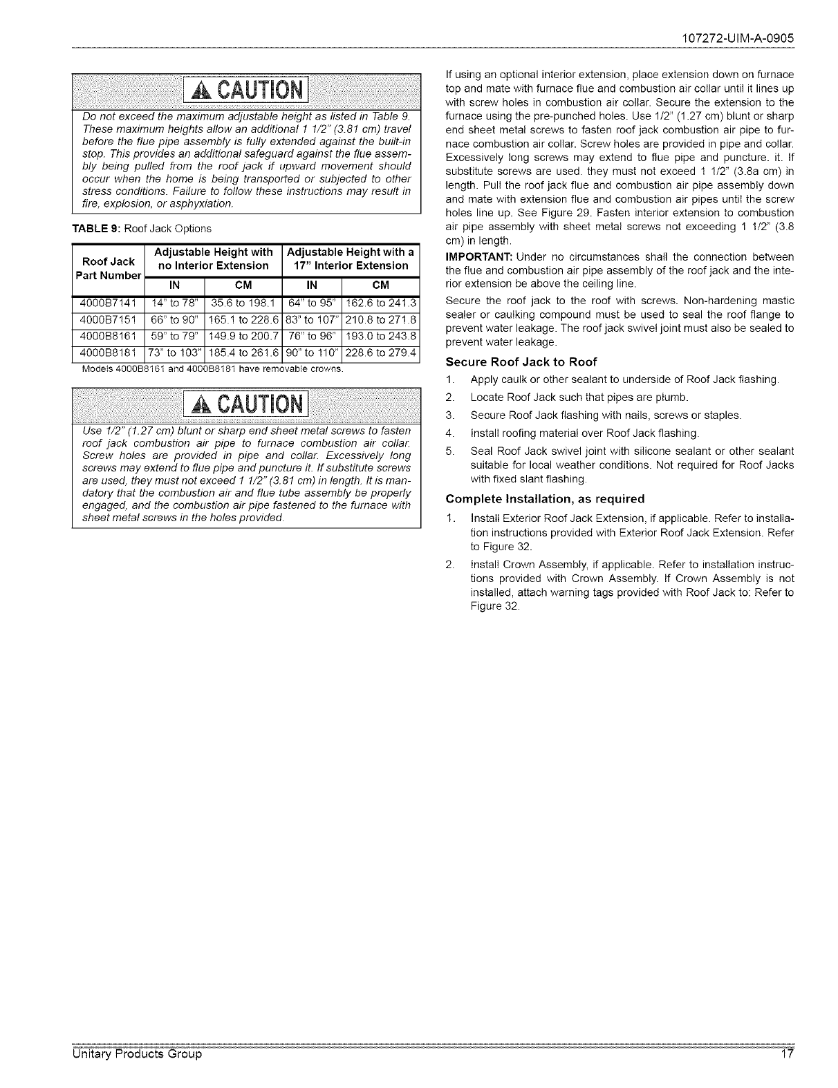
107272-UIM-A-0905
iii!!!!!i!!iiiii!!ilIiliiiii!!i!!i!!i!iii!iiii!ii!iiiili!ilJiii!ii!ii!ili!ii!ili!ii!ili!ii!ili!ii!ii!!il_ cAUTH0]i!iii!!iii!i!iliilili!i!ii!!i!i!!ii!ii!i!ii!iliii!i_iii!ilii!iili!iii!i!iii!ii!ili!i!iii!iili!iii!i!iii!ii!ii
Do not exceed the maximum adjustable height as listed in Table 9.
These maximum heights allow an additional 1 1/2" (3.81 cm) travel
before the flue pipe assembly is fully extended against the built-in
stop. This provides an additional safeguard against the flue assem-
bly being pulled from the roof jack if upward movement should
occur when the home is being transported or subjected to other
stress conditions. Failure to follow these instructions may result in
fire, explosion, or asphyxiation.
TABLE 9: Roof Jack Options
Adjustable Height with Adjustable Height with a
Roof Jack no Interior Extension 17" Interior Extension
Part Number IN CM IN CM
4000B7!41 !4" to 78" 35.6 to 198.1 64" to 95" !62.6 to 241.3
4000B7!51 66"to90" 165.1 to228.6 83"to !07" 210.8to271.8
4000B8!61 59"to79" 149.9to200.7 76"to96" 193.0to243.8
4000B8181 73" to 103" 185.4 to 261.6 90" to 110" 228.6 to 279.4
Models 4000B8161 and 4000B8181 have removabie crowns
iii!!!!!i!!iiiii!!ilIiliiiii!!i!!i!!i!iii!iiii!ii!iiiili!ilJiii!ii!ii!ili!ii!ili!ii!ili!ii!ili!ii!ii!!il_ cAuTin0]i!iii!!iii!i!iliilili!i!ii!!i!i!!ii!ii!i!ii!iliii!i_iii!ilii!iili!iii!i!:iii!ii!ili!i!iii!iili!iii!i!iii!ii!ii
Use 1/2" (1.27 cm) blunt or sharp end sheet metal screws to fasten
roof jack combustion air pipe to furnace combustion air co!lat:
Screw holes are provided in pipe and collar. Excessively long
screws may extend to flue pipe and puncture it. If substitute screws
are used, they must not exceed 1 1/2" (3.81 cm) in length. It is man-
datory that the combustion air and flue tube assembly be properly
engaged, and the combustion air pipe fastened to the furnace with
sheet metal screws in the holes provided.
If using an optional interior extension, place extension down on furnace
top and mate with furnace flue and combustion air collar until it lines up
with screw holes in combustion air collar. Secure the extension to the
furnace using the pre-punched holes. Use 1/2" (1.27 cm) blunt or sharp
end sheet metal screws to fasten roof jack combustion air pipe to fur-
nace combustion air collar. Screw holes are provided in pipe and collar.
Excessively long screws may extend to flue pipe and puncture, it. if
substitute screws are used. they must not exceed ! 1/2" (3.8a cm) in
length. Pull the roof jack flue and combustion air pipe assembly down
and mate with extension flue and combustion air pipes until the screw
holes line up. See Figure 29. Fasten interior extension to combustion
air pipe assembty with sheet metal screws not exceeding 1 1/2" (3.8
cm) in length.
IMPORTANT: Under no circumstances shall the connection between
the flue and combustion air pipe assembly of the roof jack and the inte-
rior extension be above the ceiling line.
Secure the roof jack to the roof with screws. Non-hardening mastic
sealer or caulking compound must be used to seal the roof flange to
prevent water leakage. The roof jack swivet joint must also be sealed to
prevent water leakage.
Secure Roof Jack to Roof
1. Apply caulk or other sealant to underside of Roof Jack flashing.
2. Locate Roof Jack such that pipes are plumb.
3. Secure Roof Jack flashing with nails, screws or staples.
4. Install roofing material over Roof Jack flashing.
5. Seal Roof Jack swivel joint with silicone sealant or other sealant
suitable for local weather conditions. Not required for Roof Jacks
with fixed slant flashing.
Complete Installation, as required
1. I nstalI Exterior Roof Jack Extension, if applicable. Refer to installa-
tion instructions provided with Exterior Roof Jack Extension. Refer
to Figure 32.
2. Instali Crown Assembly, if applicable. Refer to installation instruc-
tions provided with Crown Assembly. If Crown Assembly is not
installed, attach warning tags provided with Roof Jack to: Refer to
Figure 32.
Unitary Products Group 17
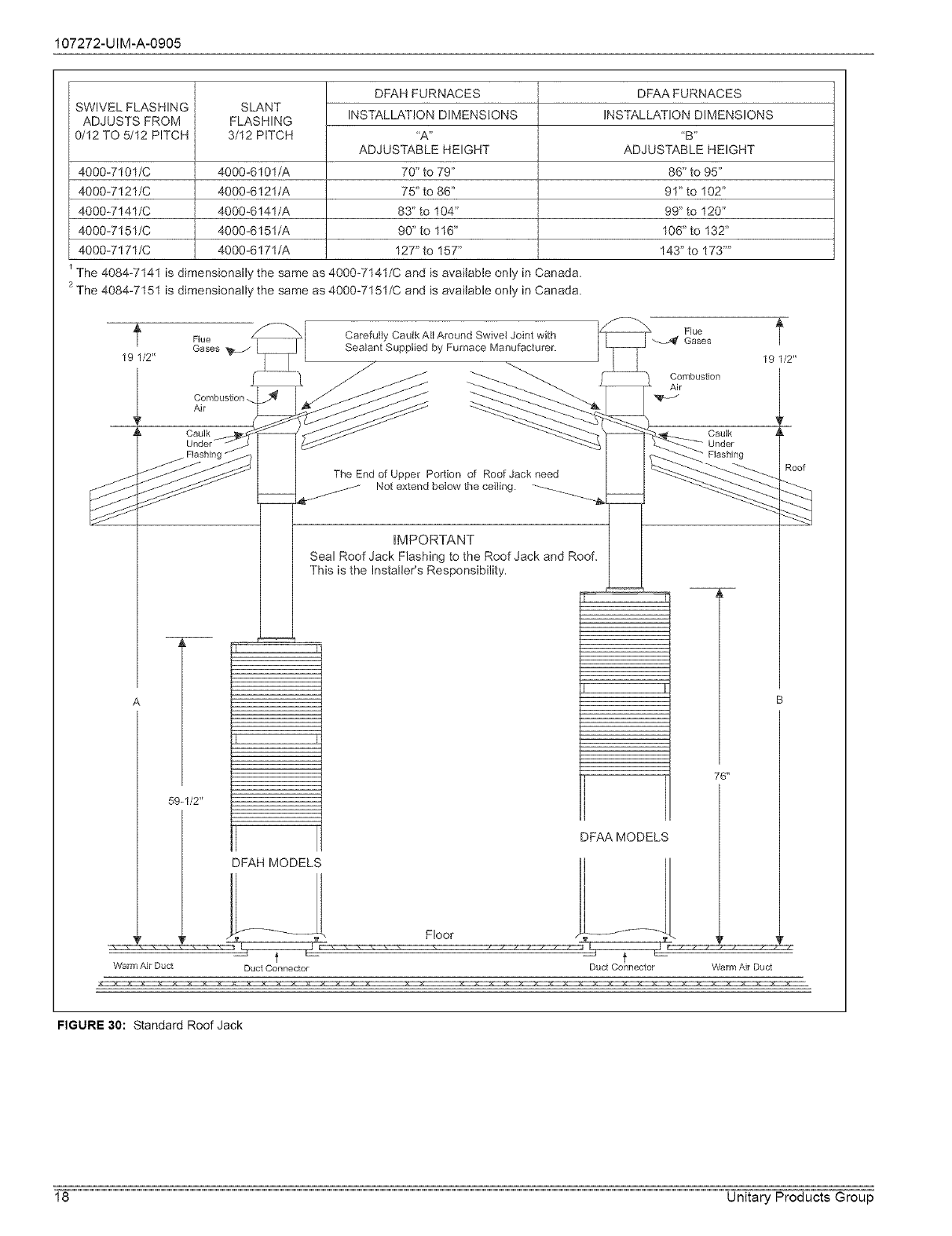
107272-UIM-A-0905
SWIVEL FLASHING
ADJUSTS FROM
0/12 TO 5/12 PITCH
4000-7101/C
4000-7121/C
4000-7141/C
4000-7151/C
4000-7171/C
SLANT
FLASHING
3/12 PITCH
4000-6101/A
4000-6121/A
4000-6141/A
4000-6151/A
4000-6171/A
DFAH FURNACES
INSTALLATION DIMENSIONS
"A"
ADJUSTABLE HEIGHT
70" to 79"
75" to 86"
83" to 104"
90" to 116"
127" to 157"
DFAA FURNACES
INSTALLATION DIMENSIONS
"B"
ADJUSTABLE HEIGHT
86" to 95"
91" to 102"
99" to 120"
106" to 132"
143" to 173 ....
The 4084-7141 is dimensionally the same as 4000-7141/C and is available only in Canada.
2 The 4084-7151 is dimensionally the same as 4000-7151/C and is available only in Canada.
f Flue
Gases
19 1/2"
Conlbustlon.
Air
Caulk
CarefuIIy Cautk AHAround Swivel Joint with
Sea_ant Supplied by Furnace Manufacturer.
The End of Upper Portion of Roof Jack need
Not extend below the ceiling. -_
Flue
"--_>_ Gases
Cjombusflon
Caulk
Unde[
..... 7_
IMPORTANT
Seal Roof Jack Flashing to the Roof Jack and Roof.
This is the Installer's Responsibility.
59-1/2"
76"
DFAA MODELS
19 1/2"
Roof
DFAH MODEL', i J----_l
Warm Air Duct Duct Connector Duct Connector Warm _,,JrDuct
FIGURE 30: Standard Roof Jack
18 Unitary Products Group
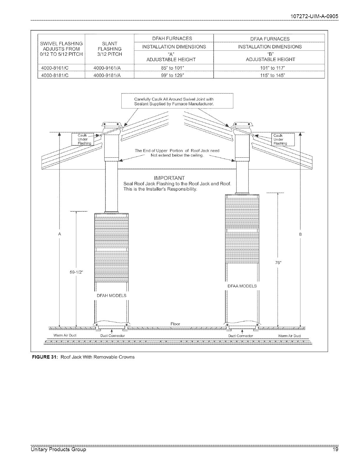
107272-UIM-A-0905
SWIVEL FLASHING
ADJUSTS FROM
0/12 TO 5/12 PITCH
SLANT
FLASHING
3/12 PITCH
4000-8161/C 4000-9161/A
4000-8181/C 4000-9181/A
DFAH FURNACES
INSTALLATION DIMENSIONS
"A"
ADJUSTABLE HEIGHT
85" to 101"
99" to 129"
DFAA FURNACES
INSTALLATION DIMENSIONS
"B"
ADJUSTABLE HEIGHT
101" to 117"
115" to 145"
Carefully Caulk Atl Around Swivei Joint with
Sealant Supplied by Furnace Manufacturer.
/
The End of Upper Portion of Roof Jack need
Not ex_end below the ceiling.
IMPORTANT
Seal Roof Jack Flashing to the Roof Jack and Roof.
This is the InstalleCs Responsibility.
59.1/2 _
76 _
DFAA MODELS
Hf------_-jjDFAHMODELS I __- _1
,_ ---\ Floor /'--" "%
T
Warm Air Duct Duct Connector Duct Connector Warm Air Duct
FIGURE 31: Roof Jack With Removable Crowns
Unitary Products Group 19
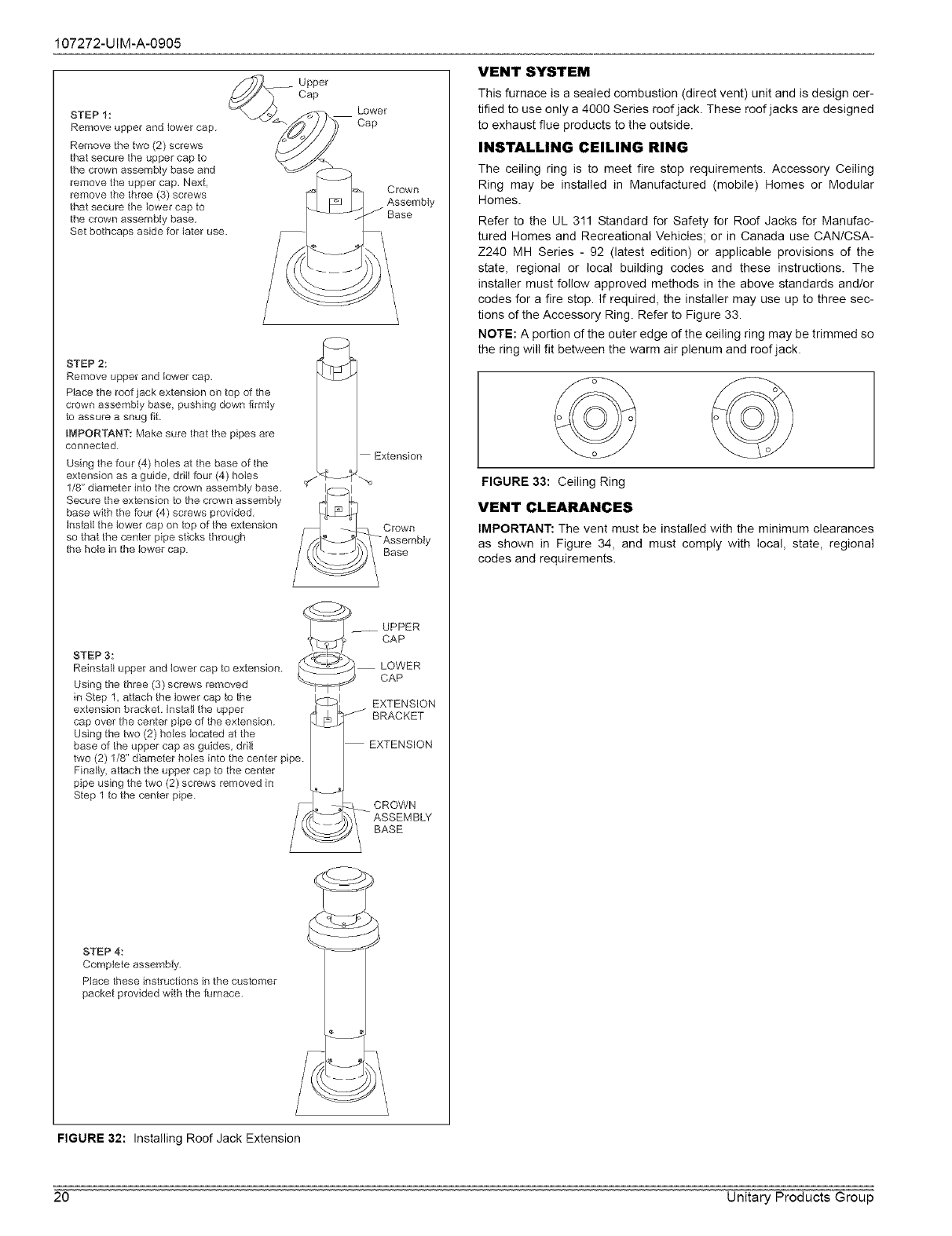
107272-UIM-A-0905
STEP 1:
Remove upper and iower cap.
Remove the two (2) screws
that secure the upper cap to
the crown assembly base and
remove the upper cap. Next,
remove the three (3) screws
that secure the lower cap to
the crown assembly base.
Set bothcaps aside for later use.
Upper
Cap
Lower
Cap
Crown
Assembly
Base
STEP 2:
Remove upper and lower cap.
Place the roof jack extension on top of the
crown assembly base pushing down firmly
to assure a snug fit.
iMPORTANT: Make sure that the pipes are
connected.
Using the four (4) holes at the base of the
extension as a guide ddti four (4) hoIes
1/8" diameter into the crown assembly base.
Secure the extension to the crown assembly
base with the four (4) screws provided.
Instalt the tower cap on top of the extension
so that the center pipe sticks through
the hole in the lower cap.
___ UPPER
cAP
STEP 3: _] LOWER
Reinstall upper and lower cap to extension. _S CAP
Using the three (3) screws removed
in Step 1 attach the tower cap to the I I
extension bracket. Insta,, the upper _j_L_- REXTAENS'ON
cap over the center pipe of the extension. _ .......
Using the two (2) holes located at the
base of the upper cap as guides, drill EXTENSION
two (2) 1/8" diameter holes into the center pipe.
Finally attach the upper cap to the center
pipe using the two (2) screws removed in L. J
step 1 to the center pipe. [_/
STEP 4:
Complete assembly.
Place these instructions in the customer
packet provided with the furnace.
VENT SYSTEM
This furnace is a sealed combustion (direct vent) unit and is design cer-
tiffed to use only a 4000 Series roof jack. These roof jacks are designed
to exhaust flue products to the outside.
INSTALLING CEILING RING
The ceiling ring is to meet fire stop requirements. Accessory Ceiling
Ring may be installed in Manufactured (mobile) Homes or Modular
Homes.
Refer to the UL 311 Standard for Safety for Roof Jacks for Manufac-
tured Homes and Recreational Vehicles; or in Canada use CANICSA-
Z240 MH Series - 92 (latest edition) or applicable provisions of the
state, regional or local building codes and these instructions. The
installer must follow approved methods in the above standards and/or
codes for a fire stop. If required, the installer may use up to three sec-
tions of the Accessory Ring. Refer to Figure 33.
NOTE: A portion of the outer edge of the ceiling ring may be trimmed so
the ring will fit between the warm air plenum and roof jack.
FIGURE 33: Ceiling Ring
VENT CLEARANCES
IMPORTANT: The vent must be installed with the minimum clearances
as shown in Figure 34, and must comply with local, state, regional
codes and requirements.
FIGURE 32: Installing Roof Jack Extension
20 Unitary Products Group

107272-UIM-A-0905
Comer Detail
[] Vent lerminal
(_ Air Supply
[] Area Where Terminal is Not Permitted
Fixed
Closed
Operable
FIGURE 34: Home Layout
Canadian Installations 1 US Installation 2
A. CIearance above grade, veranda, porch, deck, or balcony 12 inches (30 cm) 12 inches (30 cm)
12 inches (30 cm) for models <100,000 BTUH
B. CIearance to window or door that may be opened (30 kW), 36 inches (91 cm) for models > 100,000 4 Feet
BTUH (30 kW)
C Clearance to permanently ctosed window 4 Feet 4 Feet
D Vertical clearance to ventilated soffit tocated
above the terminal within a horizontal distance 4 Feet 4 Feet
of 2 feet (61 cm) from the center tine of the terminal
E. CIearance to unventilated soffit 12 Inches 12 Inches
F. Clearance to outside corner 12 Inches 12 Inches
G.Clearance to inside corner 6 Feet 6 Feet
H Clearance to each side of center line extended 3 feet (91 cm) within a height 15 feet (45 m) 3 feet (91 cm) within a height 15 feet (4.5 m)
above the
above meter/regulator assembly meter/regulator assembty above the meter/regulator assembty
I Clearance to service regulator vent outlet 3 feet (91 cm) 3 feet (91 cm)
12 inches (30 cm) for models <100,000 BTUH
J. Clearance to nonmechanical air suppty inlet to buitding (30 kW), 35 inches (91 cm) for models >100,000 4 Feet
or the combustion air inlet to any other appliance BTUH (30 kW)
3 feet (91 cm) above if within 10 feet (3 cm)
K. CIearance to a mechanical supply inlet 6 feet (1 83 m) horizontally
L CIearance above paved sidewalk or paved driveway located on
public proper_y 7 feet (213 m) € 7 feet (2.13 m) t
M.CIearance under veranda, porch, deck, or balcony 12 inches (30.4 cm) 12 inches (304 cm)
Vent Termination from any Building Surface 12" (30.4 cm) 12" (304 cm)
Above anticipated snow depth 12" (30.4 cm) 12" (304 cm)
1 In accordance with the current CSA B149 1-00, Natural Gas and Propane Installation Code
2 In accordance with the current ANSI Z223.1 /NFPA 54, National Gas Code. In accordance with the current UL 311 Standard for Safety for Roof Jacks for Manufac-
tured Homes and Recreational VeMctes.
1- A vent shalI not terminate directty above a sidewalk or paved driveway that is located between two single family dwellings and serves both dwellings.
$ Permitted only if veranda, porch, deck, or balcony is fully open on a minimum of two sides beneath the floor For clearance not specified in UL 311 Standard for
Safety for Roof Jacks for Manufactured Homes and RecreationaI Vehicles
CIearance in accordance with Iocal installation codes and the Manufacturer's Installation ManuaI
Any fresh air or make up inlet for dryer or furnace area is considered to be forced air inlet.
Avoid areas where condensate drippage may cause problems such as above planters, patios, or adjacent to windows where steam may cause fogging.
A terminus of a vent shall be either:
Fitted with a cap in accordance with the vent manufacturer's installation instructions, or In accordance with the installation instructions for a special venting system
* Does not apply to muttipte installations of this furnace mode_ Refer to "VENTING MULTIPLE UNITS" in this section of these instructions
IMPORTANT: Consideration must be given for degradation of buiIding materials by flue gases. Sidewatt termination may require sealing or shielding of buitding surfaces
with a corrosion resistant materiai to protect against combustion product corrosion. Consideration must be given to wind direction in order to prevent flue
products and/or condensate from being blown against the buitding surfaces If a metal shieId is used it must be a stainless steet matedai at a minimum
dimension of 20" (508 cm) tt is recommended that a retaining type collar be used that is attached to the buitding surface to prevent movement of the vent
pipe.
Responsibility for the provision of proper adequate venting and air supply for application shall rest with the installer
Vent shall extend high enough above building, or a neighboring obstruction, so that wind from any direction will not create a positive pressure in the vicinity of the vent
Also in accordance with the current UL 727 Standard for safety for oil-fired central furnaces.
Unitary Products Group 21
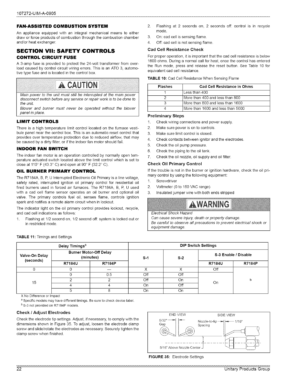
107272-UIM-A-0905
FAN-ASSISTED COMBUSTION SYSTEM
An appliance equipped with an integral mechanical means to either
draw or force products of combustion through the combustion chamber
and/or heat exchanger.
SECTION VII: SAFETY CONTROLS
CONTROL CIRCUIT FUSE
A 3-amp fuse is provided to protect the 24-volt transformer from over-
load caused by control circuit wiring errors. This is an ATO 3, automo-
tive type fuse and is located in the control box.
Main power to the unit must still be interrupted at the main power
disconnect switch before any service or repair work is to be done to
the unit.
Blower and burner must never be operated without the blower
panel in place.
LIMIT CONTROLS
There is a high temperature limit control located on the furnace vesti-
bule panel near the control box. This is an automatic reset control that
provides over temperature protection due to reduced airflow, that may
be caused by a dirty filter, or if the indoor fan motor should fail.
INDOOR FAN SWITCH
The indoor fan motor is an operation controlled by normally open tem-
perature actuated switch located above the limit control which is set to
close at 110° F (43.3 ° C) and open at 90 ° F (32.2 ° C).
OIL BURNER PRIMARY CONTROL
The R7184A, B, P, U Interrupted Electronic Oil Primary is a line voltage,
safety rated, interrupted ignition oil primary control for residential oil
fired burners used in forced air furnaces. The R7184A, B, P, U used
with a cad cell flame sensor operates an oil burner and optional oil
valve. The primary controls fuel oil, senses flame, controls ignition
spark and notifies a remote alarm circuit when in lockout.
The indicator light on the oil primary control provides lockout, recycle,
and cad cell indications as follows:
1. Flashing at 1/2 second on, 1/2 second off: system is locked out or
in restricted mode.
2. Flashing at 2 seconds on, 2 seconds off: controi is in recycle
mode.
3. On: cad cell is sensing flame.
4. Off: cad cell is not sensing flame.
Cad Cell Resistance Check
For proper operation, it is important that the cad cell resistance is below
1600 ohms. During a normal call for heat, once the controI has entered
the Run mode, press and release the reset button. See Table !0 for
equivalent cad cell resistance.
TABLE 10: Cad Cell Resistance When Sensing Ftame
Flashes Cad Cell Resistance in Ohms
1 Less than 400
2 More than 400 and less than 800
3 More than 800 and less than 1600
4 More than 1600 and less than 5000
Preliminary Steps
1. Check wiring connections and power supply.
2. Make sure power is on to controls.
3. Make sure limit control is closed.
4. Check contacts between ignitor and the electrodes.
5. Check the oil pump pressure.
6. Check the piping to the oil tank.
7. Check the oil nozzle, oil supply and oil filter.
Check Oil Primary Control
If the trouble is not in the burner or ignition hardware, check the oil pri-
mary control by using the following equipment:
1. Screwdriver
2. Voltmeter (0 to 150 VAC range)
3. Insulated jumper wire with both ends stripped
Electrical Shock Hazard
Can cause severe injury, death or property damage.
Be careful to observe all precautions to prevent electrical shock or
equipment damage.
Valve-On Delay
(seconds)
TABLE 11: Timings and Settings
Delay Timings a
Burner Motor-Off Delay
(minutes)
15
X No Difference or Impact
R7184U
0
0
2
4
5
R7184P
0.5
2
4
8
a Specific models may havedifferent timings. Be sure to check device labet.
b S-3 not provided on R7184P models.
Check /Adjust Electrodes
Check the electrode tip settings. Adjust, if necessary, to comply with the
dimensions shown in Figure 35. To adjust, loosen the electrode clamp
screw and slide/rotate the electrodes as necessary. Securely tighten the
clamp screw when finished.
S-1
X
Off
Off
On
On
DIP Switch Settings
S-2
X
Off
On
Off
On
S-3 Enable /Disable
R7184U R7184P
Off
b
On
END ViEW
Gap
SiDE VIEW
Nozzle--to-ti
Spacing
5/16 '_Above Nozzte Center
FIGURE 35: Electrode Settings
22 Unitary Products Group
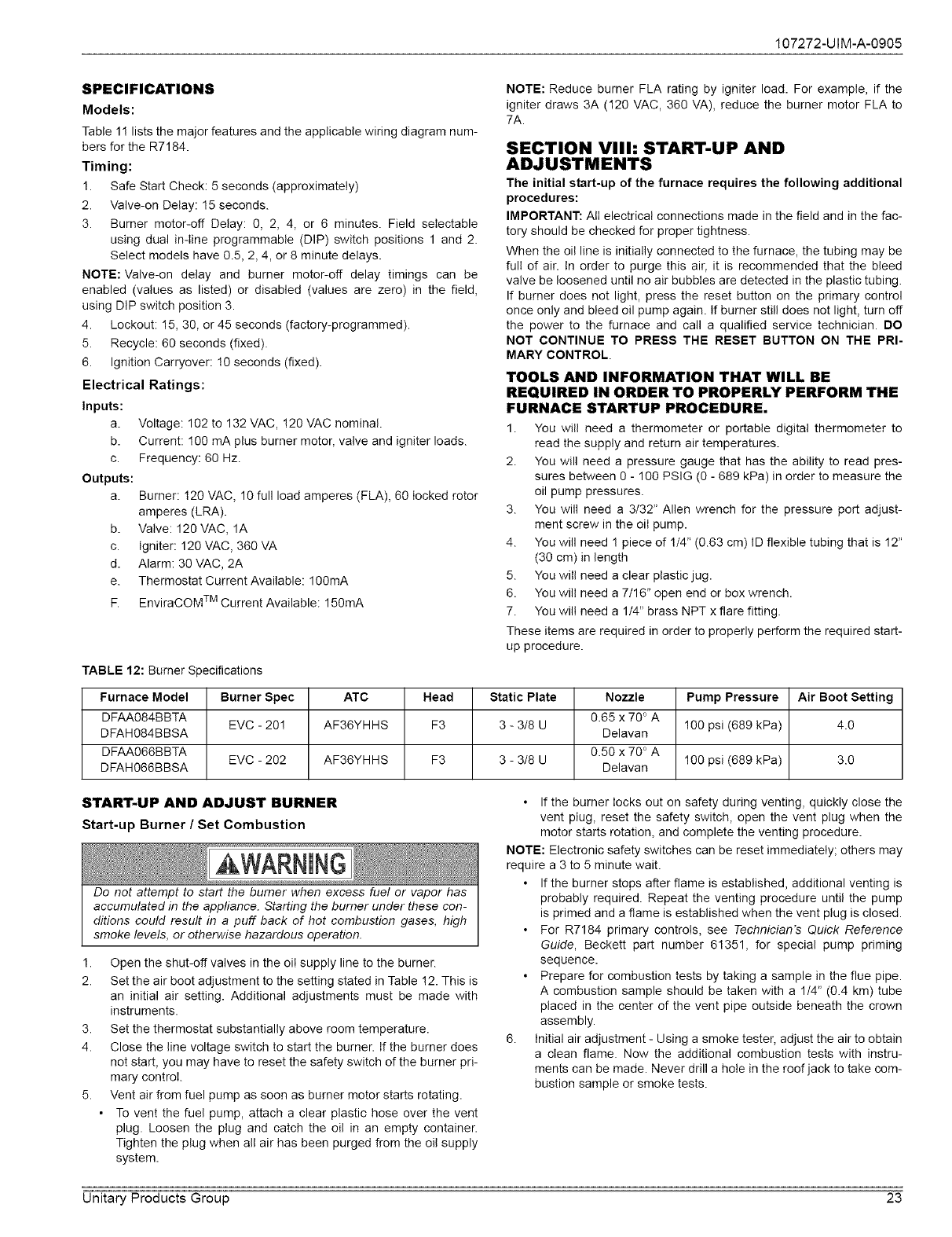
107272-UIM-A-0905
SPECIFICATIONS
Models:
Table 1! lists the major features and the applicable wiring diagram num-
bers for the R7184.
Timing:
1. Safe Start Check: 5 seconds (approximately)
2. Valve-on Delay: 15 seconds.
3. Burner motor-off Delay: 0, 2, 4, or 6 minutes. Field seIectable
using dual in-line programmable (DIP) switch positions 1 and 2.
Select models have 0.5, 2, 4, or 8 minute delays.
NOTE: Valve-on delay and burner motor-off delay timings can be
enabled (values as listed) or disabled (values are zero) in the field,
using DiP switch position 3.
4. Lockout: 15, 30, or 45 seconds (factory-programmed).
5. Recycle: 60 seconds (fixed).
6. Ignition Carryover: !0 seconds (fixed).
Electrical Ratings:
Inputs:
a.
b.
C.
Outputs:
a.
Voltage: 102 to 132 VAC, !20 VAC nominal.
Current: 100 mA plus burner motor, valve and igniter loads.
Frequency: 60 Hz.
Burner: 120 VAC, 10 full load amperes (FLA), 60 locked rotor
amperes (LRA).
b. Valve: 120 VAC, 1A
c. Igniter: 120 VAC, 360 VA
d. Alarm: 30 VAC, 2A
e. Thermostat Current Available: 100mA
F. EnviraCOM TM Current Available: 150mA
TABLE 12: Burner Specifications
NOTE: Reduce burner FLA rating by igniter load. For example, if the
igniter draws 3A (120 VAC, 360 VA), reduce the burner motor FLA to
7A.
SECTION Vllh START-UP AND
ADJUSTMENTS
The initial start-up of the furnace requires the following additional
procedures:
IMPORTANT: All electrical connections made in the field and in the fac-
tory should be checked for proper tightness.
When the oil line is initially connected to the furnace, the tubing may be
full of air. In order to purge this air, it is recommended that the bleed
valve be loosened until no air bubbles are detected in the plastic tubing.
If burner does not light, press the reset button on the primary control
once only and bleed oil pump again. If burner still does not light, turn off
the power to the furnace and call a qualified service technician. DO
NOT CONTINUE TO PRESS THE RESET BUTTON ON THE PRI-
MARY CONTROL.
TOOLS AND INFORMATION THAT WILL BE
REQUIRED IN ORDER TO PROPERLY PERFORM THE
FURNACE STARTUP PROCEDURE•
1. You will need a thermometer or portable digital thermometer to
read the supply and return air temperatures.
2. You will need a pressure gauge that has the ability to read pres-
sures between 0 - 100 PSlG (0 - 689 kPa) in order to measure the
oil pump pressures.
3. You will need a 3/32" Allen wrench for the pressure port adjust-
ment screw in the oil pump.
4. You will need 1 piece of 1/4" (0.63 cm) ID flexible tubing that is 12"
(30 cm) in length
5. You will need a clear plastic jug.
6. You will need a 7/16" open end or box wrench.
7. You will need a 1/4" brass NPT x flare fitting.
These items are required in order to properly perform the required start-
up procedure.
Furnace Model Burner Spec ATC Head Static Plate Nozzle Pump Pressure Air Boot Setting
DFAA084BBTA 0.65 x 70 ° A
DFAH084BBSA EVC - 20! AF36YHHS F3 3 - 3/8 U Delavan 100 psi (689 kPa) 4.0
DFAA066BBTA 0.50 x 70 ° A
DFAH066BBSA EVC - 202 AF36YHHS F3 3 - 3/8 U Delavan 100 psi (689 kPa) 3.0
START-UP AND ADJUST BURNER
Start-up Burner /Set Combustion
Do not attempt to start the burner when excess fuel or vapor has
accumulated in the appliance. Starting the burner under these con-
ditions could result in a puff back of hot combustion gases, high
smoke levels, or otherwise hazardous operation.
1.
2.
3.
4.
5.
Open the shut-off valves in the oil supply line to the burner.
Set the air boot adjustment to the setting stated in Table !2. This is
an initial air setting. Additional adjustments must be made with
instruments.
Set the thermostat substantially above room temperature.
Close the line voltage switch to start the burner. If the burner does
not start, you may have to reset the safety switch of the burner pri-
mary control.
Vent air from fuel pump as soon as burner motor starts rotating.
To vent the fuel pump, attach a clear plastic hose over the vent
plug. Loosen the plug and catch the oil in an empty container.
Tighten the plug when all air has been purged from the oil supply
system.
• If the burner locks out on safety during venting, quickly close the
vent plug, reset the safety switch, open the vent ptug when the
motor starts rotation, and complete the venting procedure.
NOTE: Electronic safety switches can be reset immediately; others may
require a 3 to 5 minute wait.
• If the burner stops after flame is established, additional venting is
probably required. Repeat the venting procedure until the pump
is primed and a flame is established when the vent plug is closed.
• For R7184 primary controls, see Technician's Quick Reference
Guide, Beckett part number 61351, for special pump priming
sequence.
• Prepare for combustion tests by taking a sample in the flue pipe.
A combustion sample should be taken with a 114" (0.4 km) tube
placed in the center of the vent pipe outside beneath the crown
assembly.
6. Initial air adjustment - Using a smoke tester, adjust the air to obtain
a clean flame. Now the additional combustion tests with instru-
ments can be made. Never drill a hole in the roof jack to take com-
bustion sample or smoke tests.
Unitary Products Group 23
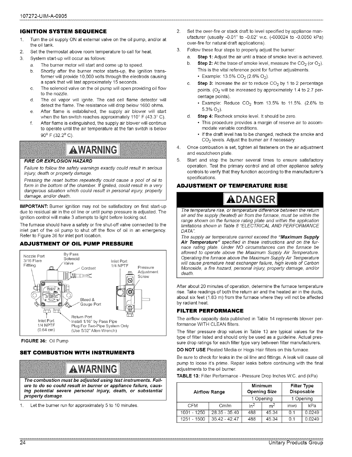
107272-UIM-A-0905
IGNITION SYSTEM SEQUENCE
1. Turn the oil supply ON at external valve on the oil pump, and/or at
the oil tank.
2. Set the thermostat above room temperature to call for heat.
3. System start-up will occur as follows:
a. The burner motor will start and come up to speed.
b. Shortly after the burner motor starts-up, the ignition trans-
former will provide 10,000 volts through the electrods causing
a spark that will last approximately 15 seconds.
c. The solenoid valve on the oil pump will open providing oil flow
to the nozzle.
d. The oil vapor will ignite. The cad cell flame detector will
detect the flame. The resistance will drop below 1600 ohms.
e. After flame is established, the supply air blower will start
when the fan switch reaches approximately 110 ° F (43.3 ° C).
f. After flame is extinguished, the supply air blower will continue
to operate until the air temperature at the fan switch is below
90° F (32.2 ° C).
FIRE OR EXPLOSION HAZARD
Failure to follow the safety warnings exactly could result in serious
injury, death or property damage.
Pressing the reset button repeatedly could cause a pool of oil to
form in the bottom of the chamber. If ignited, could result in a very
dangerous situation which could result in personal injury, property
damage, and/or death.
IMPORTANT: Burner ignition may not be satisfactory on first start-up
due to residual air in the oil line or until pump pressure is adjusted. The
ignition control will make 3 attempts to light before locking out.
The furnace should have a safety or fire shut-off valve connected to the
inlet part of the oil pump to shut off the flow of oil in an emergency.
Refer to Figure 36 for inlet port location.
ADJUSTMENT OF OIL PUMP PRESSURE
Nozzle Port By Pass
3/16 Flare Solenoid Inlet Pert
1/4 NPTF
(0.64 cm) Plug For Two-Pipe System Only
(Use 5/32" Alien Wrench)
FIGURE 36: Oil Pump
SET COMBUSTION WITH INSTRUMENTS
kWARNING
The combustion must be adjusted using test instruments. Fail-
ure to do so could result in burner or appliance failure, caus-
ing potential severe personal injury, death, or substantial
property damage.
1. Let the burner run for approximately 5 to 10 minutes.
2. Set the over-fire or stack draft to level specified by appliance man-
ufacturer (usually -0.01" to -0.02" w.c. (-000024 to -0.0050 kPa)
over-fire for natural draft applications).
3. Follow these four steps to properly adjust the burner:
a. Step 1: Adjust the air until a trace of smoke level is achieved.
b. Step 2: At the trace of smoke level, measure the CO 2(or 02).
This is the vital reference point for further adjustments.
• Example: 13.5% CO2 (2.6% 02).
c. Step 3: Increase the air to reduce CO 2 by 1 to 2 percentage
points. (02 will be increased by approximately ! .4 to 2.7 per-
centage points).
• Example: Reduce CO 2 from 13.5% to 1!.5%. (2.6% to
5.3% 02).
d. Step 4: Recheck smoke level. It should be zero.
• This procedure provides a margin of reserve air to accom-
modate variable conditions.
• If the draft level has to be changed, recheck the smoke and
CO 2 levels. Adjust the burner air if necessary.
4. Once combustion is set, tighten all fasteners on the air adjustment
and escutcheon plate.
5. Start and stop the burner several times to ensure satisfactory
operation. Test the primary control and all other appliance safety
controls to verify that they function according to the manufacturer's
specifications.
ADJUSTMENT OF TEMPERATURE RISE
kDANGER
The temperature rise, or temperature difference between the return
air and the supply (heated) air from the furnace, must be within the
range shown on the furnace rating plate and within the application
limitations shown in Table 8 "ELECTRICAL AND PERFORMANCE
DATA".
The supply air temperature cannot exceed the "Maximum Supply
Air Temperature" specified in these instructions and on the fur-
nace rating plate. Under NO circumstances can the furnace be
allowed to operate above the Maximum Supply Air Temperature.
Operating the furnace above the Maximum Supply Air Temperature
will cause premature heat exchanger failure, high levels of Carbon
Monoxide, a fire hazard, personal injury, property damage, and/or
death.
After about 20 minutes of operation, determine the furnace temperature
rise. Take readings of both the return air and the heated air in the ducts,
about six feet (1.83 m) from the furnace where they will not be affected
by radiant heat.
FILTER PERFORMANCE
The airflow capacity data published in Table 14 represents blower per-
formance WITH CLEAN filters.
The filter pressure drop values in Table 13 are typical values for the
type of filter listed and should only be used as a guideline. Actual pres-
sure drop ratings for each filter type vary between filter manufacturers.
DO NOT USE Pleated Media or Hogs Hair filters on this furnace.
Be sure to check for leaks in the oil line and fittings. A leak wiii cause oil
pump to loose it's prime. Repair leaks before continuing with the final
adjustments to the oil burner.
TABLE 13: Filter Performance - Pressure Drop Inches W.C. and (kPa)
Airflow Range
CFM Cm/m
1001 -!250 28.35- 35.40
1251 -!500 35.42- 42.47
Minimum
Opening Size
1 Opening
in2 m2
488 45.34
488 45.34
Filter Type
Disposable
1 Opening
inwc kPa
0.1 0.0249
0.1 0.0249
24 Unitary Products Group
107272-UIM-A-0905
APPLYING FILTER PRESSURE DROP TO
DETERMINE SYSTEM AIRFLOW
Example: For a 84,000 BTUH (38.06 kW) furnace with 1 return open-
ings and operating on high-speed blower, it is found that total system
static is 0.30" w.c. (0.075 kPa). To determine the system airflow, com-
plete the following steps:
Obtain the airflow values at 0.!0 w.c. (125 Pa) & 0.20 w.c. (150 Pa)
ESR
Airflow @ 0.!0": 1175 CFM (60.17 m3/min)
Airflow @ 0.20": !110 CFM (57.62 m3/min)
Subtract the airflow @ 0.10 w.c. (!25 Pa) from the airflow @ 0.20 w.c.
(150 Pa) to obtain airflow difference.
1175 - 11!0 = -65 CFM (2.55 m3/min)
Subtract the total system static from 0.10 w.c. (125 Pa) and divide this
difference by the difference in ESP values in the table, 0.20 w.c.
(150 Pa) - 0.10 w.c. (125 Pa), to obtain a percentage.
(0.30 - 0.10) /(0.20 - 0.10) = 0.5
Multiply percentage by airflow difference to obtain airflow reduction.
(0.5) X (-65) = -32.5
Subtract airflow reduction value to airflow @ 0.10 w.c. (125 Pa) to
obtain actual airflow @ 0.30 wc (144 Pa) ESP.
1050 - 32.5 = 1017.5
FINAL PROCEDURE
Install Furnace Doors
Install the lower door first by sliding the bottom of the door down until
the tabs on the casing base engage the slots in the bottom door end
cap. Then push the top of the lower door in until the door clips snap into
place. Install the upper door in a similar manner, first engaging the slots
in the top of the upper door on the tabs on the casing top. Then snap
the bottom of the upper door into place against the casing.
Finish and Trim
Alcove and Closet Installations may now be finished and trimmed as
necessary.
TABLE 14: Blower Performance CFM
Blower Speed
Single Speed - No Coii
Single Speed - With Dry Coil
BLOWER PERFORMANCE CFM - DFAA066
FACTORY EQUIPPED WITH STANDARD BLOWERS AND FILTERS
BTU/H (kW)
Input /Output
66(19.34) /53(15.55)
66(19.34) /53(15.55)
CFM
(m3/min)
1050(29.73)
!050(29.73)
EXTERNAL STATIC PRESSURE, INCHES WC (kPa)
0.1 (0,025) 0.2 (0,050) 0.3 (0,075) 0.4 (0,099) 0.5 (0,124)
cfm cm/m cfm cm/m cfm cm/m cfm cm/m cfm cm/m
1175 33.3 1110 3! .4 1050 29.7 1000 28.3 950 26.9
1125 31.9 !070 30.3 !020 28.9 960 27.2 910 25.8
BLOWER PERFORMANCE CFM -DFAA084
Blower Speed
Single Speed - No Coil
Single Speed - With Dry Coil
EXTERNAL STATIC PRESSURE,
BTU/H (kW) CFM 0.1 (0,025) 0.2 (0,050) 0.3 (0,075)
Input /Output (m 3 /min) cfm cm/m cfm cm/m cfm cm/m
84(24.62) /67(19.63) 1250(35.39) 1370 38.8 1305 37.0 1245 35.3
84(24.62) /67(19.63) !250(35.39) !265 35.8 1195 33.8 1120 31.7
BLOWER PERFORMANCE CFM -DFAH066
INCHES WC (kPa)
0.4 (0,099) 0.5 (0,124)
cfm cm/m cfm cm/m
!175 33.3 !100 31.1
!045 29.6 !015 28.7
Blower Speed
Single Speed - No Coil
EXTERNAL STATIC PRESSURE,
BTU/H (kW) CFM 0.1 (0.025) 0.2 (0.050) 0.3 (0.075)
Input /Output (m 3 /min) cfm cm/m cfm cm/m cfm cm/m
66(!9.34)/53(15.55 1050(29.73) !155 32.7 1111 31.5 1055 29.9
BLOWER PERFORMANCE CFM -DFAH084
INCHES WC (kPa)
0.4 (0.099) 0.5 (0.124)
cfm cm/m cfm cm/m
995 28.2 920 26. !
EXTERNAL STATIC
BTU/H (kW) CFM 0.1 (0.025) 0.2 (0.050) 0.3 (0.075)
Blower Speed Input /Output (m 3 /min) cfm cm/m cfm cm/m
Single Speed - No CoiI 84(24.62) /67(19.63) 1250(35.39) 1127 31.9 1062 30.1
NOTES:
1. Airflow expressed in standard cubic feet per minute (cfm) and in cubic meters per minute (cm!m)
2. Return air is through Iouvered filter door only.
3. Motor voltage at 1!5V
PRESSURE, INCHES WC (kPa)
0.4 (0.099) 0.5 (0.124)
cfm cm/m cfm cm/m cfm cm/m
1005 28.5 952 27.0 887 25.1
Unitary Products Group 25
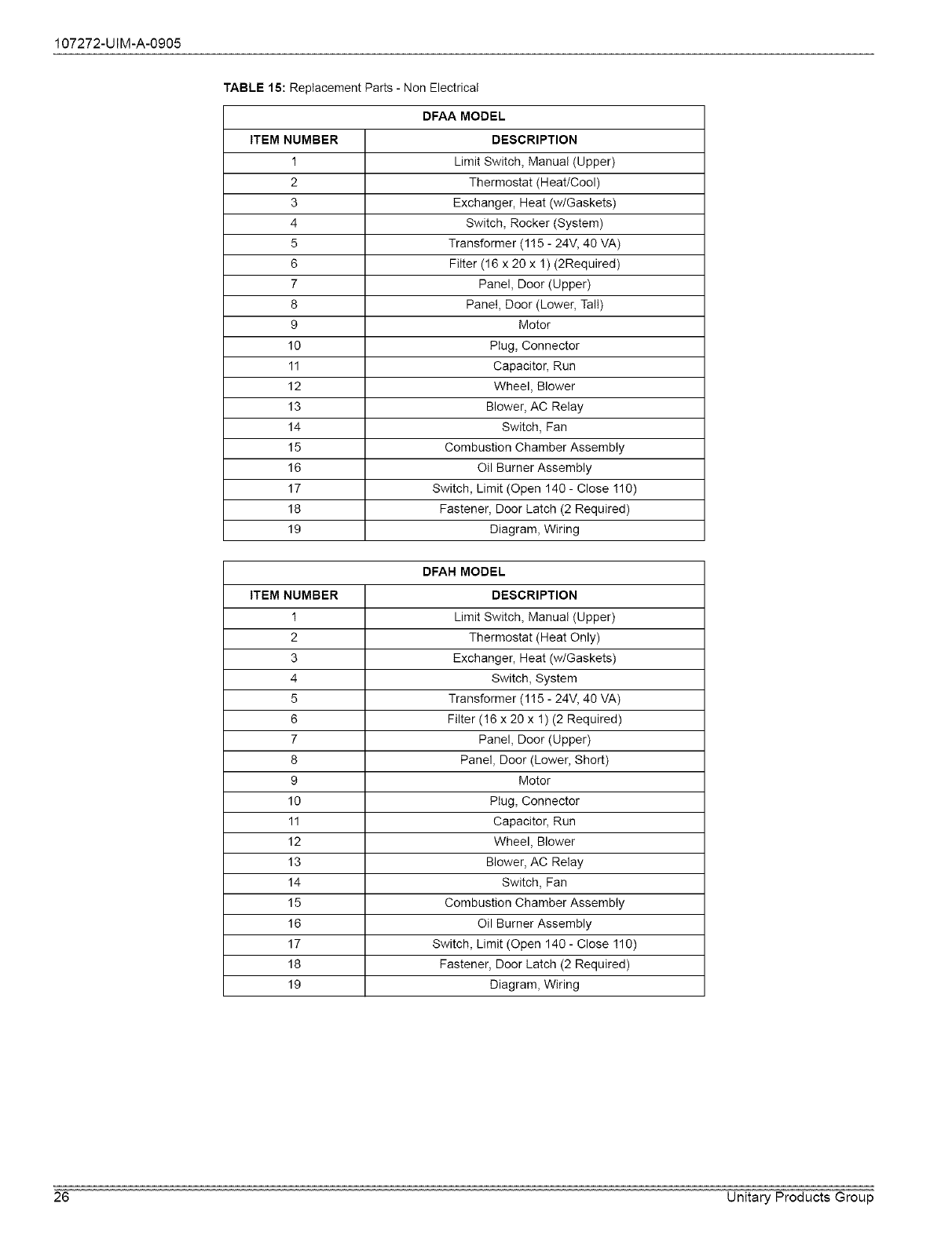
107272-UIM-A-0905
TABLE 15: Replacement Parts - Non Electrical
DFAA MODEL
ITEM NUMBER DESCRIPTION
1 Limit Switch, Manual (Upper)
2 Thermostat (Heat/Cool)
3 Exchanger, Heat (w/Gaskets)
4 Switch, Rocker (System)
5 Transformer (115 - 24V, 40 VA)
6 Filter (16 x 20 x !) (2Required)
7 Panel, Door (Upper)
8 Panel, Door (Lower, Tall)
9 Motor
10 Plug, Connector
11 Capacitor, Run
12 Wheel, Blower
13 Blower, AC Relay
14 Switch, Fan
15 Combustion Chamber Assembly
16 Oil Burner Assembly
17 Switch, Limit (Open 140 - Close !10)
18 Fastener, Door Latch (2 Required)
19 Diagram, Wiring
DFAH MODEL
ITEM NUMBER DESCRIPTION
1 Limit Switch, Manual (Upper)
2 Thermostat (Heat Only)
3 Exchanger, Heat (w/Gaskets)
4 Switch, System
5 Transformer (115 - 24V, 40 VA)
6 Filter (!6 x 20 x !) (2 Required)
7 Panel, Door (Upper)
8 Panel, Door (Lower, Short)
9 Motor
10 Plug, Connector
11 Capacitor, Run
12 Wheel, Blower
13 Blower, AC Relay
14 Switch, Fan
15 Combustion Chamber Assembly
16 Oil Burner Assembly
17 Switch, Limit (Open 140 - Close !10)
18 Fastener, Door Latch (2 Required)
19 Diagram, Wiring
26 Unitary Products Group
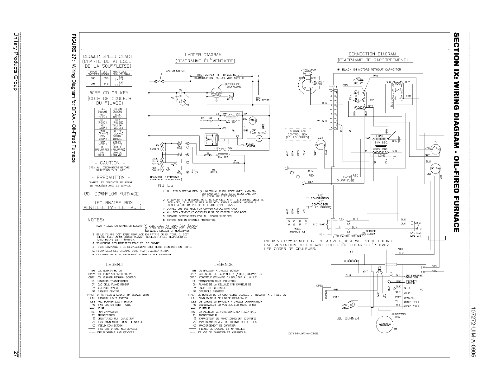
"13
C
nl
¢€
g
3
_>
i
_o.
3-
77
77
C
3
o
BLOWER SPEED CHART
(CHARTE DE VITEBBE
DE LA BOUFFLERIE]
z_ 24v CONNECTIONROOMTHERMOSTAT
0 FIELD CONNECTION
FACTORYWIRING ANO OEVICES
FIELO WIRING AND OEWCES
LADDER DIAGRAM
(DIADRAMME ELEMENTAZRE)
z_ 2€v RACCOROEMENTOU THERMOSTATDE PIECE
0 RACCOROEMENTDE CHANTIER
FILAGE OE L'USINE ET APPAREILS
FILAGE DE CHANTIER ET APPAREILS
CONNECTION DIAGRAM
{DIAGRAMME DE RACCORDEMENT)
e+ BLACK ON MOTORS WITHOUT CAPACITOR
OZL BURNER
o
c
,>
o
o
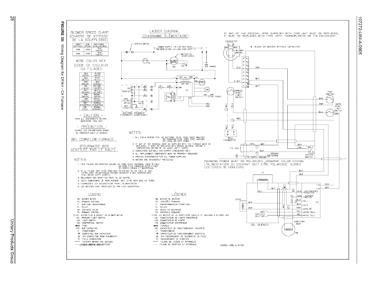
'1rll
5
C_
m
O0
B
I
&
3
0
BLOWER SPEED CHART
CHARTE DE VITESSE
DE LA SOUFFLERIE)
WIRE COLOR KEY
(CODE DE COULEUR
DU FILAGE)
BLACK
CNOIR]
BLUE
(BLEU) [BLEU]
RED
(ROUGE)
YELLOW
(JAUN] (JAUNE)
_T WHITE
(BLANC) (BLANC)
BRN BRO_N
(BRUN) [BRUN}
8RN GREEN
(VERT) (VERT]
PRP PURPLE
(POURPRE) (POURPRE)
ORN ORANGE
(ORA) IORANBE)
CAUTION
OPEN ALL DISCONNECTS BEFORE
SERVICING THIS UNIT
PRECAUTION
OUVREZ LES DISJONCTEURS AVANT
DE PROC£DER AVEC LE SERVICE
80+ DOWNFLOW FURNACE
(FOURNAISE 80X
VENTILEE PAR LE HAUTI
LADDER DIAGRAM
(DIAGRAMME ELEMENTAIRE)
SYSTEM _ POWER SUPPLY 115 I 60 SEE NOTE I _ I
SWITCH
IALIMENTATION 115 I 60 VO[R NOTE I]
@FS
L --J
HEAT/COOL THERWOSTAT
ITHERMOSTAT CL[MA/CHAUF)
NOTES=
I, ALL FIELD WIRING PER: [A) NATIONAL ELEC, COBE [NEC} AND/OR/
(B) CANADIAN ELEC CODE {CEC) AND/OR/
[C) LOCAL OR CITY GODE_
2, [F ANY OF THE ORIGINAL WIRE AS SUPPLIED WITH THE FURNACE MUST BE
REPLACED, IT MUST BE REPLACED WITH _R]NG MATERIAL HAVING A
TEMPERATURE RATING OF AT LEAST Z21"F {105"C)
3 CONNECTORS SUITABLE FOR COPPER CONDUCTORS ONLY
4 ALL REPLACEMENT COMPONENTS MUST BE PROPERLY GROUNDED,
5, PROVIDE DISCONNECTS FOR ALL POWER SUPPLIES,
NOTES= _. MOTORSARE_NHERENTLYPROTECTED.
I, TOUT F[LAGE EN CHANT]ER SELON, (A} CODE ELEC,,NAT[ONAL (GEN} ET/OU/
/_/COOLELECCANAO_E.COEC_ET/OU/
CODES LOCAUX ET MUN[CIPAUX,
Z, S( LE F[LAGE DOIT ET_E REMPLACE EN P_TRIE OU EN TOUT, Ih DOIT
L'ETRE AVEC UN MATERIAUX POUVANT RESISTER A DES TEMPERATURES
D'AU MO[N5 Z21"F (lOS"C).
5, SEULEMENT DES MARETTES POUR FIE DE CU[VRE,
€, TOUTE COMPOSANTE DE REMPLACEMENT DOIT [ETRE BIEN M[SE EN TERRE,
B, FOURN[£SEZ LES D[SJONCTEURS POUR L'AL[MENTA]TON
6, LES MOTEURS SONT PROTEGES' DE PAR LEUR CONCEPTION,
IF ANY OF THE ORIGINAL WIRE SUPPLIED WITH THIS UNIT MUST BE REPLACED,
IT MUST BE REPLACED WITH TYPE IOB'C THERMQPLASTIC OR ITS EQUIVALENT.
CAPACITOR
BLACK ON MOTORS WITHOUT CAPACITOR
WALL
ORG
VCqT
WHT
[
NEU_ WHT
SYSTEM
SWZTCH
INCOMING POWER MUST BE POLARIZED. OBSERVE COLOR COOZNG.
L'ALIMENTATION DU COURANT DOIT E_RE POLARIBEE." SUIVEZ
LES CODES DE COULEURB.
WHT
LEGEND LE'GENDE
BM BURNER MOTOR BM MOTEUR DU BRU_EUR OPSV
PC PRIMARY CONTROL PC CONTR_LE PRIMAIRE
[T IGNITION TRANSFORMER [T TRANSFORMATEUR D'IGN[T]ON
RI RELAY RI RELA]£
SV SOL[NO[D VALVE SV SOUPE DU SOLENO[DE
PC PRIMARY CONTROL PC CONTROLE PRIMA(RE
PI/SI 9 PIN PLUG & SOCKET ON BLO_R MOTOR PI/SI LE MOTEUR DE LA SOUFFLER[E OOUILLE ET BOUCHON A 9 P[GES BUR
LSI PRIMARY LIMIT £W]TGH LSI COMMUTATEUR DE L[M[TE PR[NGIPALE
LS2 LIMIT £W[TCH LS2 GOMMUTATEUR DE LIM[TE
CS CENTRIFICAL SWITCH CS COMMUTATEUR CENTRIF[QUE
FUSE _ FUSIBLE
IRC RUN CAPACITOR IRC CAPAC[TEUR DE FONCT[ONNEMENT (DENT(FIE
IT TRANSFORMER IT TRANSFORMEUR
(_ IDENTIFIED RUN CAPACITOR (_ CAPACITEUR DE FONCT[ONNEMENT I[3ENTIFIE
Z4V CONNECT(ON ROOM THERMOSTAT _ Z4V RACCOROEMENT DU THERMOSTAT DE PIECE
O FIELD CONNECT(ON O RACCORDEMENT DE CHANTER
FACTORY WIRING AND DEVICES FILA_E DE L'USINE ET APPAREILS
1_2_1_!_ _N_ _EV[CES F]LAGE BE CHANT[ER ET APPARE[LS 1589_1 UWD A ©705
_T
wHT
PRP
OIL BURNER
JUNCTION
_OX
_ IBM
FAN
SWITCH
ORG
PRP AUTO
RESET
BLU _ _H
,>
g
o
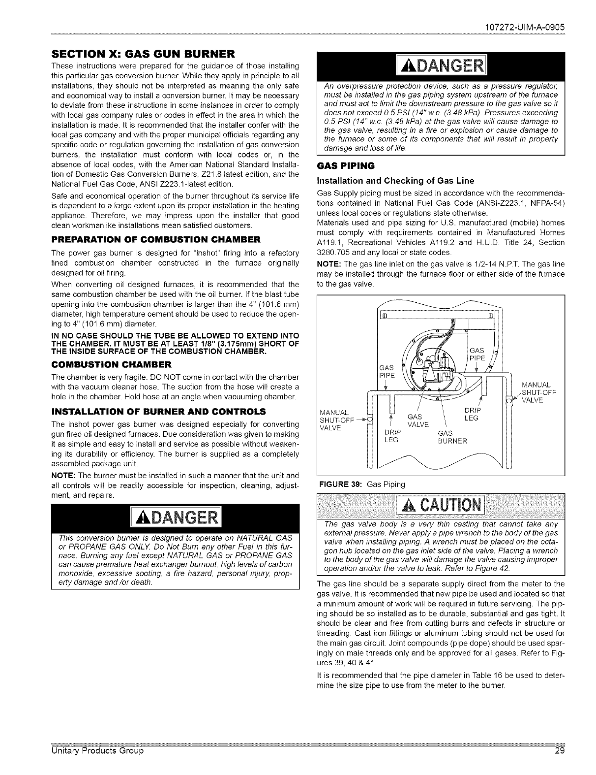
107272-UIM-A-0905
SECTION X: GAS GUN BURNER
These instructions were prepared for the guidance of those installing
this particular gas conversion burner. While they apply in principle to all
installations, they should not be interpreted as meaning the only safe
and economical way to install a conversion burner. It may be necessary
to deviate from these instructions in some instances in order to comply
with local gas company rules or codes in effect in the area in which the
installation is made. It is recommended that the installer confer with the
local gas company and with the proper municipal officials regarding any
specific code or regulation governing the installation of gas conversion
burners, the installation must conform with local codes or, in the
absence of local codes, with the American National Standard Installa-
tion of Domestic Gas Conversion Burners, Z21.8 latest edition, and the
National Fuel Gas Code, ANSI Z223. l-latest edition.
Safe and economical operation of the burner throughout its service life
is dependent to a large extent upon its proper installation in the heating
appliance. Therefore, we may impress upon the installer that good
clean workmanlike installations mean satisfied customers.
PREPARATION OF COMBUSTION CHAMBER
The power gas burner is designed for "inshot" firing into a refactory
lined combustion chamber constructed in the furnace originally
designed for oil firing.
When converting oil designed furnaces, it is recommended that the
same combustion chamber be used with the oil burner. If the blast tube
opening into the combustion chamber is larger than the 4" (101.6 mm)
diameter, high temperature cement should be used to reduce the open-
ing to 4" (101.6 mm) diameter.
IN NO CASE SHOULD THE TUBE BE ALLOWED TO EXTEND INTO
THE CHAMBER, IT MUST BE AT LEAST 1/8" (3,175mm) SHORT OF
THE INSIDE SURFACE OF THE COMBUSTION CHAMBER.
COMBUSTION CHAMBER
The chamber is very fragile. DO NOT come in contact with the chamber
with the vacuum cleaner hose. The suction from the hose will create a
hole in the chamber. Hold hose at an angle when vacuuming chamber.
INSTALLATION OF BURNER AND CONTROLS
The inshot power gas burner was designed especially for converting
gun fired oil designed furnaces. Due consideration was given to making
it as simple and easy to install and service as possible without weaken-
ing its durability or efficiency. The burner is supplied as a completely
assembled package unit.
NOTE: The burner must be installed in such a manner that the unit and
all controls will be readily accessible for inspection, cleaning, adjust-
ment, and repairs.
This conversion burner is designed to operate on NATURAL GAS
or PROPANE GAS ONLX Do Not Burn any other Fue! in this fur-
nace. Burning any fue! except NATURAL GAS or PROPANE GAS
can cause premature heat exchanger burnout, high levels of carbon
monoxide, excessive sooting, a fire hazard, personal injury, prop-
erty damage and/or death.
ADANGER
An overpressure protection device, such as a pressure regulator,
must be installed in the gas piping system upstream of the fumace
and must act to limit the downstream pressure to the gas valve so it
does not exceed 0.5 PSI (!4" w.c. (3.48 kPa). Pressures exceeding
0.5 PSI (14" w.c. (3.48 kPa) at the gas valve wil! cause damage to
the gas valve, resulting in a fire or explosion or cause damage to
the furnace or some of its components that will result in property
damage and loss of life.
GAS PIPING
Installation and Checking of Gas Line
Gas Supply piping must be sized in accordance with the recommenda-
tions contained in National Fuel Gas Code (ANSI-Z223.1, NFPA-54)
unless local codes or regulations state otherwise.
Materials used and pipe sizing for U.S. manufactured (mobile) homes
must comply with requirements contained in Manufactured Homes
Al19.1, Recreational Vehicles A!19.2 and H.U.D. Title 24, Section
3280.705 and any local or state codes.
NOTE: The gas line inlet on the gas valve is 1/2-14 N.P.T. The gas line
may be installed through the furnace floor or either side of the furnace
to the gas valve.
MANUAL
SHUT-OFF
VALVE
LEG
DRIP GAS
LEG BURNER
MANUAL
,_/SHUT-OFF
VALVE
FIGURE 39: Gas Piping CAUTt0]
The gas valve body is a very thin casting that cannot take any
external pressure. Never apply a pipe wrench to the body of the gas
valve when installing piping. A wrench must be placed on the octa-
gon hub located on the gas inlet side of the valve. Placing a wrench
to the body of the gas valve wil! damage the valve causing improper
operation and/or the valve to leak. Refer to Figure 42.
The gas line should be a separate supply direct from the meter to the
gas valve. It is recommended that new pipe be used and located so that
a minimum amount of work will be required in future servicing. The pip-
ing should be so installed as to be durable, substantial and gas tight. It
should be clear and free from cutting burrs and defects in structure or
threading. Cast iron fittings or aluminum tubing should not be used for
the main gas circuit. Joint compounds (pipe dope) should be used spar-
ingly on male threads only and be approved for all gases. Refer to Fig-
ures 39, 40 & 41.
It is recommended that the pipe diameter in Table 16 be used to deter-
mine the size pipe to use from the meter to the burner.
Unitary Products Group 29
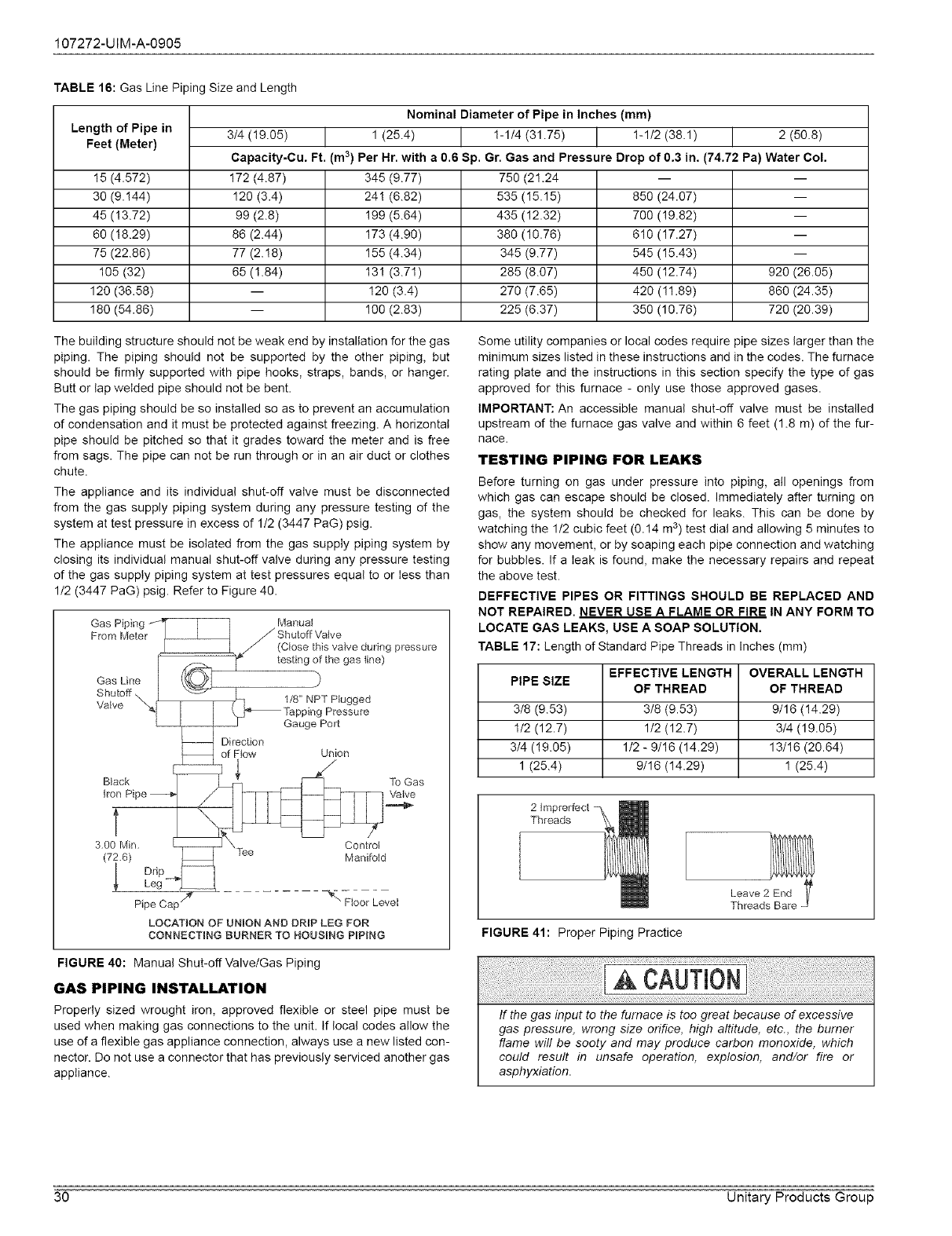
107272-UIM-A-0905
TABLE 16: Gas Line Piping Size and Length
Nominal Diameter of Pipe in Inches (mm)
Length of Pipe in 3/4 (!9.05) 1 (25.4) !-1/4 (31.75) !-1/2 (38.1) 2 (50.8)
Feet (Meter) Capacity-Cu. Ft. (m3) Per Hr. with a 0.6 Sp. Gr. Gas and Pressure Drop of 0.3 in. (74.72 Pa) Water Col.
15 (4.572) 172 (4.87) 345 (9.77) 750 (21.24 -- --
30 (9.!44) 120 (3.4) 24! (6.82) 535 (15.15) 850 (24.07) --
45 (!3.72) 99 (2.8) !99 (5.64) 435 (!2.32) 700 (!9.82) --
60 (18.29) 86 (2.44) 173 (4.90) 380 (10.76) 610 (17.27) --
75 (22.86) 77 (2.!8) 155 (4.34) 345 (9.77) 545 (15.43) --
105 (32) 65 (1.84) 13! (3.71) 285 (8.07) 450 (12.74) 920 (26.05)
120 (36.58) -- 120 (3.4) 270 (7.65) 420 (!1.89) 860 (24.35)
180 (54.86) -- 100 (2.83) 225 (6.37) 350 (10.76) 720 (20.39)
The building structure should not be weak end by installation for the gas
piping. The piping should not be supported by the other piping, but
should be firmly supported with pipe hooks, straps, bands, or hanger.
Butt or lap welded pipe should not be bent.
The gas piping should be so installed so as to prevent an accumulation
of condensation and it must be protected against freezing. A horizontal
pipe should be pitched so that it grades toward the meter and is free
from sags. The pipe can not be run through or in an air duct or clothes
chute.
The appliance and its individual shut-off valve must be disconnected
from the gas supply piping system during any pressure testing of the
system at test pressure in excess of 1/2 (3447 PaG) psig.
The appliance must be isolated from the gas supply piping system by
closing its individual manual shut-off valve during any pressure testing
of the gas supply piping system at test pressures equal to or Iess than
1/2 (3447 PaG) psig. Refer to Figure 40.
Gas Line
Shutoff,
Valve
ManuaI
Shutoff Valve
(Close this valve during pressure
testing of the gas line)
1/8" NPT Plugged
Pressure
Gauge Port
Direction
of Flow Union
Black
t
3.00 Min.
Pipe
To Gas
Valve
LOCATION OF UNION AND DRiP LEG FOR
CONNECTING BURNER TO HOUSING PiPiNG
Some utility companies or local codes require pipe sizes larger than the
minimum sizes listed in these instructions and in the codes. The furnace
rating plate and the instructions in this section specify the type of gas
approved for this furnace - only use those approved gases.
IMPORTANT: An accessible manual shut-off valve must be installed
upstream of the furnace gas valve and within 6 feet (1.8 m) of the fur-
Race.
TESTING PIPING FOR LEAKS
Before turning on gas under pressure into piping, atl openings from
which gas can escape should be closed. Immediately after turning on
gas, the system should be checked for leaks. This can be done by
watching the 1/2 cubic feet (0.14 m 3) test dial and allowing 5 minutes to
show any movement, or by soaping each pipe connection and watching
for bubbles. If a Ieak is found, make the necessary repairs and repeat
the above test.
DEFFECTIVE PIPES OR FITTINGS SHOULD BE REPLACED AND
NOT REPAIRED. NEVER USE A FLAME OR FIRE IN ANY FORM TO
LOCATE GAS LEAKS, USE A SOAP SOLUTION.
TABLE 17: Length of Standard Pipe Threads in Inches (mm)
EFFECTIVE LENGTH OVERALL LENGTH
PIPE SIZE OF THREAD OF THREAD
3/8 (9.53) 3/8 (9.53) 9/16 (!4.29)
1/2 (12.7) 1/2 (12.7) 3/4 (19.05)
3/4 (!9.05) 1/2 - 9/16 (14.29) 13/16 (20.64)
1 (25.4) 9/16 (14.29) 1 (25.4)
2 Imprerfect
Threads
FIGURE 41: Proper Piping Practice
Leave2 End I/
Threads Bare J
FIGURE 40: Manual Shut-offValve/Gas Piping
GAS PIPING INSTALLATION
Properly sized wrought iron, approved flexible or steel pipe must be
used when making gas connections to the unit. If local codes allow the
use of a flexible gas appliance connection, always use a new listed con-
nector. Do not use a connector that has previously serviced another gas
appliance.
........
If the gas input to the furnace is too great because of excessive
gas pressure, wrong size orifice, high altitude, etc., the burner
flame will be sooty and may produce carbon monoxide, which
could result in unsafe operation, explosion, and/or fire or
asphyxiation.
30 Unitary Products Group
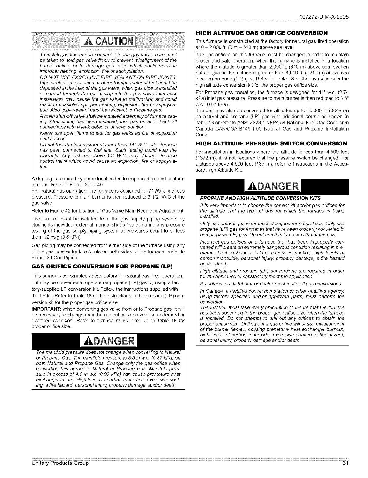
107272-UIM-A-0905
To install gas line and to connect it to the gas valve, care must
be taken to hold gas valve firmly to prevent misalignment of the
burner orifice, or to damage gas valve which could result in
improper heating, explosion, fire or asphyxiation.
DO NOT USE EXCESSIVE PIPE SEALANT ON PIPE JOINTS.
Pipe sealant, metal chips or other foreign material that could be
deposited in the inlet of the gas valve, when gas pipe is installed
or carried through the gas piping into the gas valve inlet after
installation, may cause the gas valve to malfunction and could
result in possible improper heating, explosion, fire or asphyxia-
tion. Also, pipe sealant must be resistant to Propane gas.
A main shut-off valve shaft be installed externally of furnace cas-
ing. After piping has been installed, turn gas on and check all
connections with a leak detector or soap solution.
Never use open flame to test for gas leaks as fire or explosion
could occur.
Do not test the fuel system at more than !4" W. C. after furnace
has been connected to fuel line. Such testing could void the
warranty. Any test run above !4" tAZC. may damage furnace
control valve which could cause an explosion, fire or asphyxia-
tion.
A drip leg is required by some local codes to trap moisture and contam-
inations. Refer to Figure 39 or 40.
For natural gas operation, the furnace is designed for 7" W.C. inlet gas
pressure. Pressure to main burner is then reduced to 3 1/2" W.C at the
gas valve.
Refer to Figure 42 for location of Gas Valve Main Regulator Adjustment.
The furnace must be isolated from the gas supply piping system by
closing its individual external manual shut-oft valve during any pressure
testing of the gas supply piping system at pressures equal to or less
than 1/2 psig (3.5 kPa).
Gas piping may be connected from either side of the furnace using any
of the gas pipe entry knockouts on both sides of the furnace. Refer to
Figure 39 Gas Piping.
GAS ORIFICE CONVERSION FOR PROPANE (LP)
This burner is constructed at the factory for natural gas-fired operation,
but may be converted to operate on propane (LP) gas by using a fac-
tory-supplied LP conversion kit. Follow the instructions supplied with
the LP kit. Refer to Table 18 or the instructions in the propane (LP) con-
version kit for the proper gas orifice size.
IMPORTANT: When converting gas valve from or to Propane gas, it will
be necessary to change main burner orifice to prevent an underfired or
overfired condition. Refer to furnace rating plate or to Table 18 for
proper orifice size.
,&DANGER
The manifold pressure does not change when converting to Natural
or Propane Gas. The manifold pressure is 3.5 in w.c. (0.87 kPa) on
both Natural and Propane Gas. Change only the gas orifice when
converting this burner to Natural or Propane Gas. Manifold pres-
sure in excess of 4.0 in w.c (0.99 kPa) can cause premature heat
exchanger failure. High levels of carbon monoxide, excessive soot-
ing, a fire hazard, personal injury, property damage, and/or death.
HIGH ALTITUDE GAS ORIFICE CONVERSION
This furnace is constructed at the factory for natural gas-fired operation
at 0 - 2,000 ft. (0 m - 610 m) above sea level.
The gas orifices on this furnace must be changed in order to maintain
proper and safe operation, when the furnace is installed in a location
where the altitude is greater than 2,000 ft. (616 m) above sea level on
natural gas or the altitude is greater than 4,000 ft. (1219 m) above sea
level on propane (LP) gas. Refer to Table 18 or the instructions in the
high altitude conversion kit for the proper gas orifice size.
For Propane gas operation, the furnace is designed for 11" w.c. (2.74
kPa) inlet gas pressure. Pressure to main burner is then reduced to 3.5"
w.c. (0.87 kPa).
The unit may also be converted for altitudes up to 10,000 ft. (3048 m)
on natural and propane (LP) gas with additional derate as shown in
Table 18 or refer to ANSI Z223.1 NFPA 54 National Fuel Gas Code or in
Canada CAN/CGA-B149.1-00 Natural Gas and Propane Installation
Code.
HIGH ALTITUDE PRESSURE SWITCH CONVERSION
For installation in locations where the altitude is less than 4,500 feet
(1372 m), it is not required that the pressure switch be changed, For
altitudes above 4,500 feet (137 m), refer to Instructions in the Acces-
sory High Altitude Kit.
A.DANGER
PROPANE AND HIGH ALTITUDE CONVERSION KITS
It is very important to choose the correct kit and/or gas orifices for
the altitude and the type of gas for which the furnace is being
installed.
Only use natural gas in furnaces designed for natural gas. Only use
propane (LP) gas for furnaces that have been properly converted to
use propane (LP) gas. Do not use this furnace with butane gas.
Incorrect gas orifices or a furnace that has been improperly con-
vetted wil! create an extremely dangerous condition resulting in pre-
mature heat exchanger failure, excessive sooting, high levels of
carbon monoxide, personal injury, property damage, a fire hazard
and/or death.
High altitude and propane (LP) conversions are required in order
for the appliance to satisfactory meet the application.
An authorized distributor or dealer must make all gas conversions.
In Canada, a certified conversion station or other qualified agency,
using factory specified and/or approved parts, must perform the
conversion.
The installer must take every precaution to insure that the furnace
has been converted to the proper gas orifice size when the furnace
is installed. Do not attempt to drill out any orifices to obtain the
proper orifice size. Drilling out a gas orifice will cause misalignment
of the burner flames, causing premature heat exchanger burnout,
high levels of carbon monoxide, excessive sooting, a fire hazard,
personal llW04 property damage and/or death.
Unitary Products Group 31
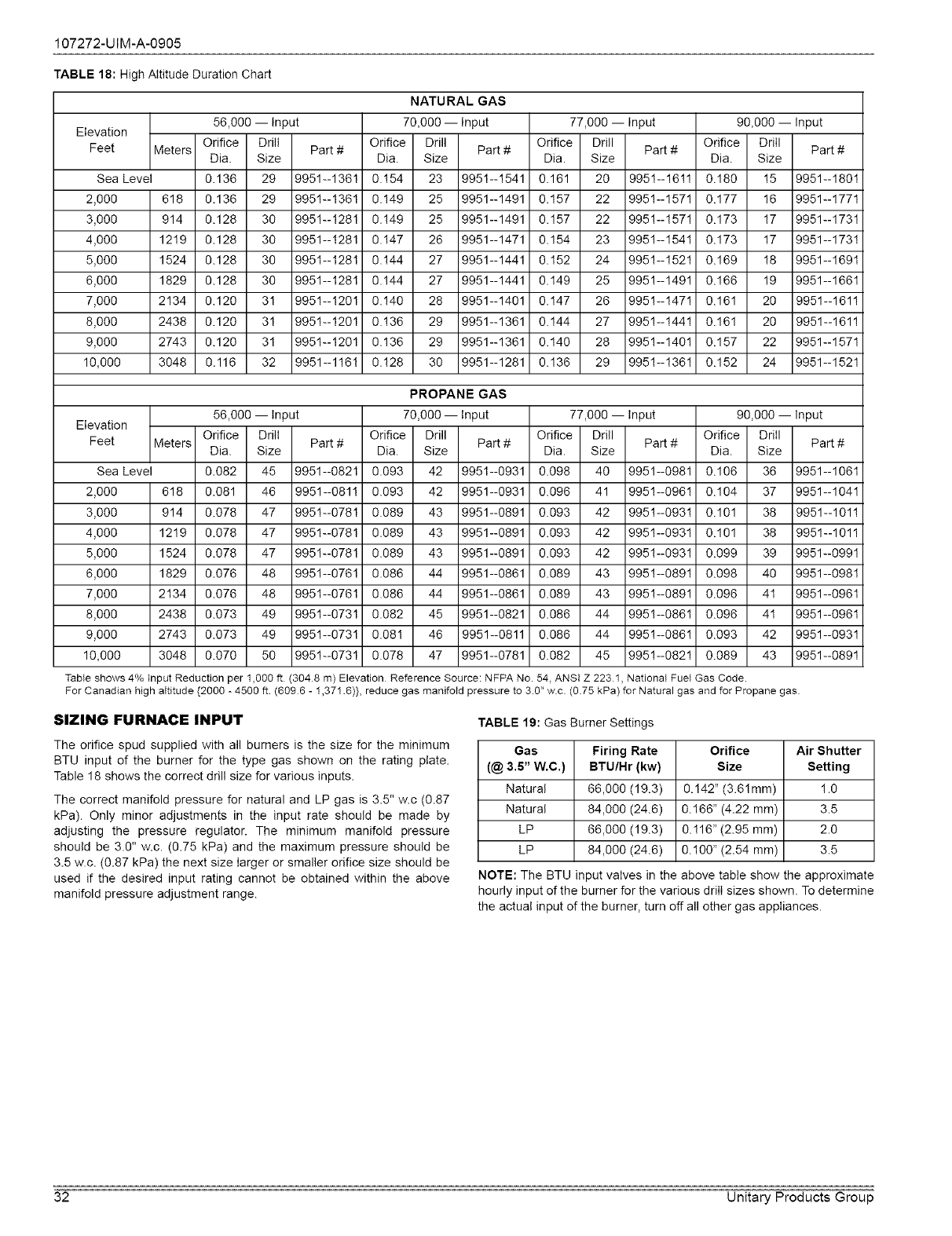
107272-UIM-A-0905
TABLE 18: High Attitude Duration Chart
NATURAL GAS
56,000 -- Input 70,000 -- Input 77,000 -- Input 90,000 -- Input
Elevation
Feet Meters Orifice Drill Part # Orifice Drill Part # Orifice Drill Part # Orifice Drill Part #
Dia. Size Dia. Size Dia. Size Dia. Size
Sea Level 0.136 29 9951--1361 0.!54 23 9951--1541 0.161 20 9951--16!1 0.180 !5 9951--1801
2,000 618 0.136 29 9951--1361 0.149 25 9951--1491 0.157 22 995!--157! 0.177 16 9951--1771
3,000 914 0.128 30 9951--1281 0.!49 25 9951--1491 0.157 22 995!--!57! 0.173 !7 9951--1731
4,000 1219 0.128 30 9951--!281 0.147 26 9951--1471 0.154 23 9951--1541 0.173 17 9951--173!
5,000 1524 0.128 30 9951--1281 0.!44 27 9951--1441 0.152 24 995!--!52! 0.169 !8 9951--1691
6,000 1829 0.128 30 9951--1281 0.144 27 9951--1441 0.149 25 995!--149! 0.166 19 9951--1661
7,000 2134 0.120 31 9951--1201 0.!40 28 9951--1401 0.147 26 995!--!47! 0.161 20 9951--161!
8,000 2438 0.120 31 9951--1201 0.!36 29 9951--1361 0.144 27 995!--!44! 0.161 20 9951--161!
9,000 2743 0.120 31 9951--1201 0.136 29 9951--1361 0.140 28 995!--140! 0.157 22 9951--1571
10,000 3048 0.116 32 9951--116! 0.!28 30 9951--1281 0.136 29 995!--!36! 0.152 24 9951--1521
PROPANE GAS
56,000 -- Input 70,000 -- Input 77,000 -- Input 90,000 -- Input
Elevation
Feet Meters Orifice Drill Part # Orifice Drill Part # Orifice Drill Part # Orifice Drill Part #
Dia. Size Dia. Size Dia. Size Dia. Size
Sea Level 0.082 45 9951--0821 0.093 42 9951--0931 0.098 40 9951--0981 0.106 36 9951--1061
2,000 618 0.081 46 9951--081! 0.093 42 9951--0931 0.096 41 995!--096! 0.104 37 9951--1041
3,000 914 0.078 47 9951--0781 0.089 43 9951--0891 0.093 42 995!--093! 0.101 38 9951--101!
4,000 1219 0.078 47 9951--0781 0.089 43 9951--0891 0.093 42 9951--0931 0.101 38 9951--1011
5,000 1524 0.078 47 9951--0781 0.089 43 9951--0891 0.093 42 995!--093! 0.099 39 9951--0991
6,000 1829 0.076 48 9951--0761 0.086 44 9951--0861 0.089 43 995!--089! 0.098 40 9951--0981
7,000 2134 0.076 48 9951--0761 0.086 44 9951--0861 0.089 43 995!--089! 0.096 41 9951--0961
8,000 2438 0.073 49 9951--0731 0.082 45 9951--0821 0.086 44 9951--0861 0.096 41 9951--0961
9,000 2743 0.073 49 9951--0731 0.081 46 9951--0811 0.086 44 995!--086! 0.093 42 9951--0931
10,000 3048 0.070 50 9951--0731 0.078 47 9951--0781 0.082 45 995!--082! 0.089 43 9951--0891
Tabte shows 4% Input Reduction per 1,000 ft (3048 m) Elevation Reference Source: NFPA No. 54, ANSI Z 2231, National Fuet Gas Code.
For Canadian high aItitude {2000 - 4500 ft (6096 - 1,371.6)}, reduce gas manifotd pressure to 3.0" w.c. (0.75 kPa) for Natural gas and for Propane gas
SIZING FURNACE INPUT
The orifice spud supplied with all burners is the size for the minimum
BTU input of the burner for the type gas shown on the rating plate.
Table 18 shows the correct drill size for various inputs.
The correct manifold pressure for natural and LP gas is 3.5" w.c (0.87
kPa). Only minor adjustments in the input rate should be made by
adjusting the pressure regulator. The minimum manifold pressure
should be 3.0" w.c. (0.75 kPa) and the maximum pressure should be
3.5 w.c. (0.87 kPa) the next size larger or smaller orifice size should be
used if the desired input rating cannot be obtained within the above
manifold pressure adjustment range.
TABLE 19: Gas Burner Settings
Gas Firing Rate Orifice Air Shutter
(@ 3.5" W.C.) BTU/Hr (kw) Size Setting
Natural 66,000 (19.3) 0.142" (3.61mm) ! .0
Natural 84,000 (24.6) 0.166" (4.22 mm) 3.5
LP 66,000 (19.3) 0.!16" (2.95 ram) 2.0
LP 84,000 (24.6) 0.100" (2.54 mm) 3.5
NOTE: The BTU input valves in the above table show the approximate
hourly input of the burner for the various drill sizes shown. To determine
the actual input of the burner, turn off all other gas appliances.
32 Unitary Products Group
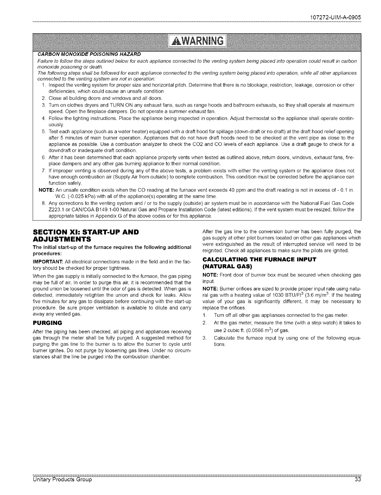
CARBON MONOXIDE POISONING HAZARD
107272-UIM-A-0905
Failure to follow the steps outlined below for each appliance connected to the venting system being placed into operation could result in carbon
monoxide poisoning or death.
The following steps shaft be followed for each appliance connected to the venting system being placed into operation, while aft other appliances
connected to the venting system are not in operation:
1. Inspect the venting system for proper size and horizontal pitch. Determine that there is no blockage, restriction, leakage, corrosion or other
deficiencies, which could cause an unsafe condition
2. Close all building doors and windows and all doors.
3. Turn on clothes dryers and TURN ON any exhaust fans, such as range hoods and bathroom exhausts, so they shall operate at maximum
speed. Open the fireplace dampers. Do not operate a summer exhaust fan.
4. Follow the lighting instructions. Place the appliance being inspected in operation. Adjust thermostat so the appliance shall operate contin-
uously.
5. Test each appliance (such as a water heater) equipped with a draft hood for spillage (down-draft or no draft) at the draft hood relief opening
after 5 minutes of main burner operation. Appliances that do not have draft hoods need to be checked at the vent pipe as close to the
appliance as possible. Use a combustion analyzer to check the CO2 and CO levels of each appliance. Use a draft gauge to check for a
downdraft or inadequate draft condition.
6. After it has been determined that each appliance properly vents when tested as outlined above, return doors, windows, exhaust fans, fire-
place dampers and any other gas burning appliance to their normal condition.
7. If improper venting is observed during any of the above tests, a problem exists with either the venting system or the appliance does not
have enough combustion air (Supply Air from outside) to complete combustion. This condition must be corrected before the appliance can
function safely.
NOTE: An unsafe condition exists when the CO reading at the furnace vent exceeds 40 ppm and the draft reading is not in excess of - 0.! in.
W.C. (-0.025 kPa) with all of the appliance(s) operating at the same time.
8. Any corrections to the venting system and /or to the supply (outside) air system must be in accordance with the National FueI Gas Code
Z223.1 or CAN/CGA B149.1-00 Natural Gas and Propane Installation Code (latest editions). If the vent system must be resized, follow the
appropriate tables in Appendix G of the above codes or for this appliance.
SECTION Xh START-UP AND
ADJUSTMENTS
The initial start-up of the furnace requires the following additional
procedures:
IMPORTANT: All electrical connections made in the field and in the fac-
tory should be checked for proper tightness.
When the gas supply is initially connected to the furnace, the gas piping
may be full of air. In order to purge this air, it is recommended that the
ground union be loosened until the odor of gas is detected. When gas is
detected, immediately retighten the union and check for leaks. Allow
five minutes for any gas to dissipate before continuing with the start-up
procedure. Be sure proper ventilation is available to dilute and carry
away any vented gas.
PURGING
After the piping has been checked, all piping and appIiances receiving
gas through the meter shall be fully purged. A suggested method for
purging the gas Iine to the burner is to allow the burner to cycle until
burner ignites. Do not purge by loosening gas lines. Under no circum-
stances shall the Iine be purged into the combustion chamber.
After the gas line to the conversion burner has been fully purged, the
gas supply at other pilot burners located on other gas appliances which
were extinguished as the result of interrupted service will need to be
reignited. Check all appliances to make sure the pilots are ignited.
CALCULATING THE FURNACE INPUT
(NATURAL GAS)
NOTE: Front door of burner box must be secured when checking gas
input.
NOTE: Burner orifices are sized to provide proper input rate using natu-
ral gas with a heating value of 1030 BTU/Ft 3 (3.6 mj/m 3. If the heating
value of your gas is significantly different, it may be necessary to
replace the orifices.
1. Turn off all other gas appliances connected to the gas meter.
2. At the gas meter, measure the time (with a stop watch) it takes to
use 2 cubic ft. (0.0566 m3) of gas.
3. Calculate the furnace input by using one of the following equa-
tions.
Unitary Products Group 33
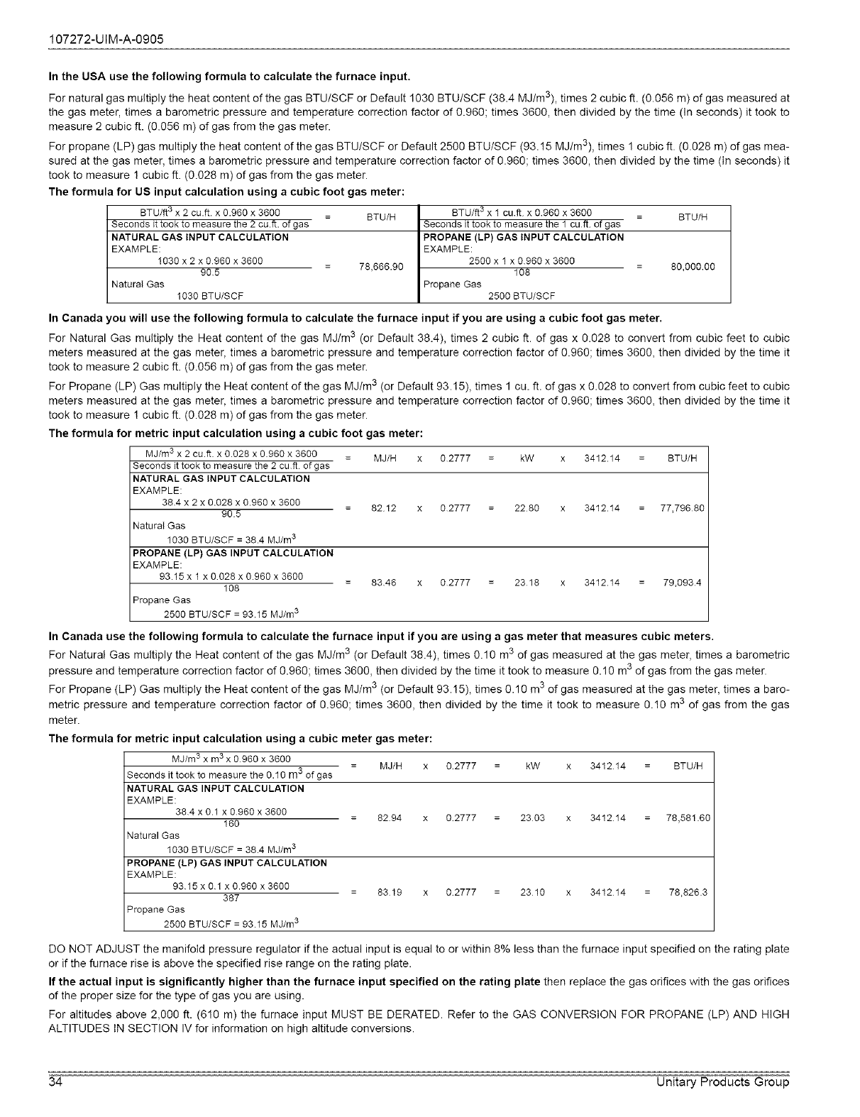
107272-UIM-A-0905
In the USA use the following formula to calculate the furnace input,
For natural gas multiply the heat content of the gas BTU/SCF or Default 1030 BTU/SCF (38.4 M j/m3), times 2 cubic ft. (0.056 m) of gas measured at
the gas meter, times a barometric pressure and temperature correction factor of 0.960; times 3600, then divided by the time (in seconds) it took to
measure 2 cubic ft. (0.056 m) of gas from the gas meter.
For propane (LP) gas multiply the heat content of the gas BTU/SCF or Default 2500 BTU/SCF (93. !5 Mj/m3), times 1 cubic ft. (0.028 m) of gas mea-
sured at the gas meter, times a barometric pressure and temperature correction factor of 0.960; times 3600, then divided by the time (In seconds) it
took to measure 1 cubic ft. (0.028 m) of gas from the gas meter.
The formula for US input calculation using a cubic foot gas meter:
BTU/ft 3 x 2 cu.ft, x 0.960 x 3600 BTU/H
Seconds it took to measure the 2 cu.ft, of gas
NATURAL GAS INPUT CALCULATION
EXAMPLE:
1030 x 2 x 0960 x 3600
905 78,666.90
Natural Gas
1030 BTU/SCF
I BTU/ft 3 x 1 cuft x 0960 x 3600 = BTU/H
Seconds it took to measure the 1 cuft of gas
PROPANE (LP) GAS INPUT CALCULATION
EXAMPLE:
2500 x 1 x 0960 x 3600
108 = 80,000 00
Propane Gas
2500 BTU/SCF
In Canada you will use the following formula to calculate the furnace input if you are using acubic foot gas meter.
For Natural Gas multiply the Heat content of the gas MJ/m 3 (or Default 38.4), times 2 cubic ft. of gas x 0.028 to convert from cubic feet to cubic
meters measured at the gas meter, times a barometric pressure and temperature correction factor of 0.960; times 3600, then divided by the time it
took to measure 2 cubic ft. (0.056 m) of gas from the gas meter.
For Propane (LP) Gas multiply the Heat content of the gas MJ/m 3 (or Default 93.15), times 1 cu. ft. of gas x 0.028 to convert from cubic feet to cubic
meters measured at the gas meter, times a barometric pressure and temperature correction factor of 0.960; times 3600, then divided by the time it
took to measure ! cubic ft. (0.028 m) of gas from the gas meter.
The formula for metric input calculation using a cubic foot gas meter:
MJ/m 3 x 2 cu.ff, x 0.028 x 0.960 x 3600 = MJ/H x
Seconds it took to measure the 2 cu ft of gas
NATURAL GAS INPUT CALCULATION
EXAMPLE:
384 x 2 x 0.028 x 0.960 x 3600 = 8212 x
90.5
Natural Gas
1030 BTU/SCF = 38.4 MJ/m 3
PROPANE (LP) GAS INPUT CALCULATION
EXAMPLE:
93.15 x 1 x 0028 x 0.960 x 3600 = 8346 x
108
Propane Gas
2500 BTU/SCF = 93.15 MJ/m 3
02777 kW 3412.14
02777 2280 3412.14
02777 2318 3412.14
BTU/H
77,79680
79,0934
In Canada use the following formula to calculate the furnace input if you are using agas meter that measures cubic meters.
For Natural Gas multiply the Heat content of the gas MJ/m 3 (or Default 38.4), times 0.10 m3 of gas measured at the gas meter, times a barometric
pressure and temperature correction factor of 0.960; times 3600, then divided by the time it took to measure 0.10 m3 of gas from the gas meter.
For Propane (LP) Gas multiply the Heat content of the gas M Jim 3 (or Default 93.!5), times 0.10 m 3of gas measured at the gas meter, times a baro-
metric pressure and temperature correction factor of 0.960; times 3600, then divided by the time it took to measure 0.10 m3 of gas from the gas
meter.
The formula for metric input calculation using a cubic meter gas meter:
MJ/m 3 x m 3x 0960 x 3600 3 MJ/H
Seconds it took to measure the 0.10 m of gas
NATURAL GAS INPUT CALCULATION
EXAMPLE:
384 x 0.1 x 0960 x 3600 8294
160
Natural Gas
1030 BTU/SCF = 38.4 MJ/m 3
PROPANE (LP) GAS INPUT CALCULATION
EXAMPLE:
9315 x 01 x 0.960 x 3600 8319
387
Propane Gas
2500 BTU/SCF = 93.15 MJ/m 3
02777 kW 341214
02777 2303 341214
02777 2310 341214
BTU/H
78,581.60
78,826.3
DO NOT ADJUST the manifold pressure regulator if the actual input is equal to or within 8% less than the furnace input specified on the rating plate
or if the furnace rise is above the specified rise range on the rating plate.
If the actual input is significantly higher than the furnace input specified on the rating plate then replace the gas orifices with the gas orifices
of the proper size for the type of gas you are using.
For altitudes above 2,000 ft. (610 m) the furnace input MUST BE DERATED. Refer to the GAS CONVERSION FOR PROPANE (LP) AND HIGH
ALTITUDES IN SECTION IV for information on high altitude conversions.
34 Unitary Products Group
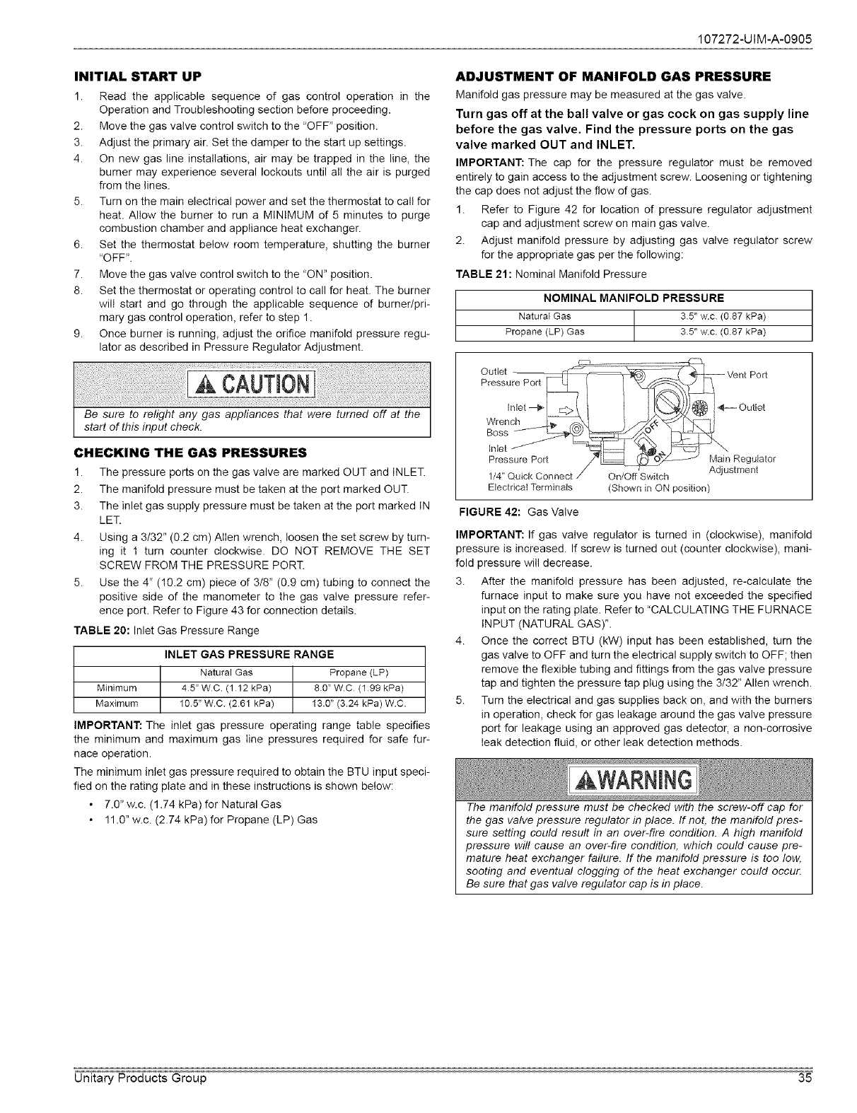
107272-UIM-A-0905
INITIAL START UP
1. Read the applicable sequence of gas control operation in the
Operation and Troubleshooting section before proceeding.
2. Move the gas valve control switch to the "OFF" position.
3. Adjust the primary air. Set the damper to the start up settings.
4. On new gas line installations, air may be trapped in the line, the
burner may experience several lockouts until all the air is purged
from the lines.
5. Turn on the main electrical power and set the thermostat to call for
heat. Allow the burner to run a MINIMUM of 5 minutes to purge
combustion chamber and appliance heat exchanger.
6. Set the thermostat below room temperature, shutting the burner
"OFF".
7. Move the gas valve control switch to the "ON" position.
8. Set the thermostat or operating control to call for heat. The burner
will start and go through the applicable sequence of burner/pri-
mary gas control operation, refer to step 1.
9. Once burner is running, adjust the orifice manifold pressure regu-
lator as described in Pressure Regulator Adjustment.
ADJUSTMENT OF MANIFOLD GAS PRESSURE
Manifold gas pressure may be measured at the gas valve.
Turn gas off at the ball valve or gas cock on gas supply line
before the gas valve. Find the pressure ports on the gas
valve marked OUT and INLET.
IMPORTANT: The cap for the pressure regulator must be removed
entirely to gain access to the adjustment screw. Loosening or tightening
the cap does not adjust the flow of gas.
1. Refer to Figure 42 for location of pressure regulator adjustment
cap and adjustment screw on main gas valve.
2. Adjust manifold pressure by adjusting gas valve regulator screw
for the appropriate gas per the following:
TABLE 21: Nominal Manifold Pressure
NOMINAL MANIFOLD PRESSURE
Natural Gas _ 35" w.c (087 kPa)
Propane (LP) Gas T35" w.c. (0.87 kPa)
CHECKING THE GAS PRESSURES
1. The pressure ports on the gas valve are marked OUT and INLET.
2. The manifold pressure must be taken at the port marked OUT.
3. The inlet gas supply pressure must be taken at the port marked IN
LET.
4. Using a 3/32" (0.2 cm) Alien wrench, loosen the set screw by turn-
ing it 1 turn counter clockwise. DO NOT REMOVE THE SET
SCREW FROM THE PRESSURE PORT.
5. Use the 4" (10.2 cm) piece of 3/8" (0.9 cm) tubing to connect the
positive side of the manometer to the gas valve pressure refer-
ence port. Refer to Figure 43 for connection details.
TABLE 20: inlet Gas Pressure Range
INLET GAS PRESSURE RANGE
Natural Gas Propane (LP)
Minimum 45" WC (112 kPa) 80 _W.C (199 kPa)
Maximum 105 _W.C (261 kPa) 130" (3.24 kPa) W.C.
IMPORTANT: The inlet gas pressure operating range table specifies
the minimum and maximum gas line pressures required for safe fur-
nace operation.
The minimum inlet gas pressure required to obtain the BTU input speci-
fied on the rating plate and in these instructions is shown below:
• 7.0" w.c. (1.74 kPa) for Natural Gas
• 11.0" w.c. (2.74 kPa) for Propane (LP) Gas
Electrical Terminals (Shown in ON position)
FIGURE 42: Gas Valve
IMPORTANT: If gas valve regulator is turned in (clockwise), manifold
pressure is increased. If screw is turned out (counter clockwise), mani-
fold pressure will decrease.
3. After the manifold pressure has been adjusted, re-calculate the
furnace input to make sure you have not exceeded the specified
input on the rating plate. Refer to "CALCULATING THE FURNACE
INPUT (NATURAL GAS)".
4. Once the correct BTU (kW) input has been established, turn the
gas valve to OFF and turn the electrical supply switch to OFF; then
remove the flexible tubing and fittings from the gas valve pressure
tap and tighten the pressure tap plug using the 3/32" Allen wrench.
5. Turn the electrical and gas supplies back on, and with the burners
in operation, check for gas leakage around the gas valve pressure
port for leakage using an approved gas detector, a non-corrosive
leak detection fluid, or other leak detection methods.
The manifold pressure must be checked with the screw-off cap for
the gas valve pressure regulator in place. If not, the manifold pres-
sure setting could result in an over-fire condition. A high manifold
pressure will cause an over-fire condition, which could cause pre-
mature heat exchanger failure. If the manifold pressure is too low,
sooting and eventual clogging of the heat exchanger could occur.
Be sure that gas valve regulator cap is in place.
Unitary Products Group 35
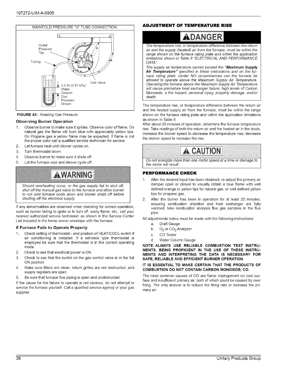
107272-UIM-A-0905
MAINFOLD PRESSURE "U" TUBE CONNECTION
F_
Outlet
Pressure
Tap
Tubing
Gas Valve
3.5 IN (0.87 kPa)
Water
Cotumn
Gas
Pressure
Shown
FIGURE 43: Reading Gas Pressure
Observing Burner Operation
1. Observe burner to make sure it ignites. Observe color of flame. On
natural gas the flame will burn blue with appreciably yellow tips.
On Propane gas a yellow flame may be expected. If flame is not
the proper color call a qualified service technician for service.
2. Let furnace heat until blower cycles on.
3. Turn thermostat down.
4. Observe burner to make sure it shuts off.
5. Let the furnace cool and blower cycle off.
Should overheating occur, or the gas supply fail to shut off,
shut off the manual gas valve to the furnace and allow burner
to run until furnace cools down and blower shuts off before
shutting off the electrical supply.
If any abnormalities are observed when checking for correct operation,
such as burner failing to ignite or to turn off, sooty flame, etc., call your
nearest authorized service technician as shown in the Service Center
List included in the home owner envelope with the furnace.
If Furnace Fails to Operate Properly
1. Check setting of thermostat - and position of HEAT/COOL switch if
air conditioning is installed. If a set-back type thermostat is
employed be sure that the thermostat is in the correct operating
mode.
2. Check to see that electrical power is ON.
3. Check to see that the switch on the gas control valve is in the full
ON position.
4. Make sure filters are clean, return grilles are not obstructed, and
supply registers are open.
5. Be sure that furnace flue piping is open and unobstructed.
If the cause for the failure to operate is not obvious, do not attempt to
service the furnace yourself. Call a qualified service agency or your gas
supplier.
ADJUSTMENT OF TEMPERATURE RISE
The temperature rise, or temperature difference between the return
air and the supply (heated) air from the furnace, must be within the
range shown on the furnace rating plate and within the application
limitations shown in Table 8 "ELECTRICAL AND PERFORMANCE
DATA".
The supply air temperature cannot exceed the "Maximum Supply
Air Temperature" specified in these instructions and on the fur-
nace rating plate. Under NO circumstances can the furnace be
allowed to operate above the Maximum Supply Air Temperature.
Operating the furnace above the Maximum Supply Air Temperature
will cause premature heat exchanger failure, high levels of Carbon
Monoxide, a fire hazard, personal injury, property damage, and/or
death.
The temperature rise, or temperature difference between the return air
and the heated supply air from the furnace, must be within the range
shown on the furnace rating plate and within the application limitations
as shown in Table 8.
After about 20 minutes of operation, determine the furnace temperature
rise. Take readings of both the return air and the heated air in the ducts.
Increase the blower speed to decrease the temperature rise; decrease
the blower speed to increase the rise.
PERFORMANCE CHECK
1. After the desired input has been obtained, re-adjust the primary air
damper open or closed to visually obtain a blue flame with welt
defined orange or yellow tips for natural gas, or well defined yellow
tips for propane gas.
2. After the burner has been in operation for at least 20 minutes,
assuring combustion chamber and heat exchanger are fully
warmed, take combustion analysis flue gas samples in the flue
pipe.
All adjustments below must be made with the following instructions:
a. Draft Gauge
b. 02 or CO 2 Analyzer
c. CO Tester
d. Water Column Gauge
NOTE: ALWAYS USE RELIABLE COMBUSTION TEST INSTRU-
MENTS. BEING PROFICIENT IN THE USE OF THESE INSTRU-
MENTS AND INTERPRETING THE DATA IS NECESSARY FOR
SAFE, RELIABLE AND EFFICIENT BURNER OPERATION
IT IS ESSENTIAL TO MAKE CERTAIN THAT THE PRODUCTS OF
COMBUSTION DO NOT CONTAIN CARBON MONOXIDE, CO.
The most common causes of CO are flame impingement on cool sur-
face and insufficient primary air, both of which could be caused by over
firing. The only answer is to reduce the firing rate or increase the pri-
mary air.
36 Unitary Products Group
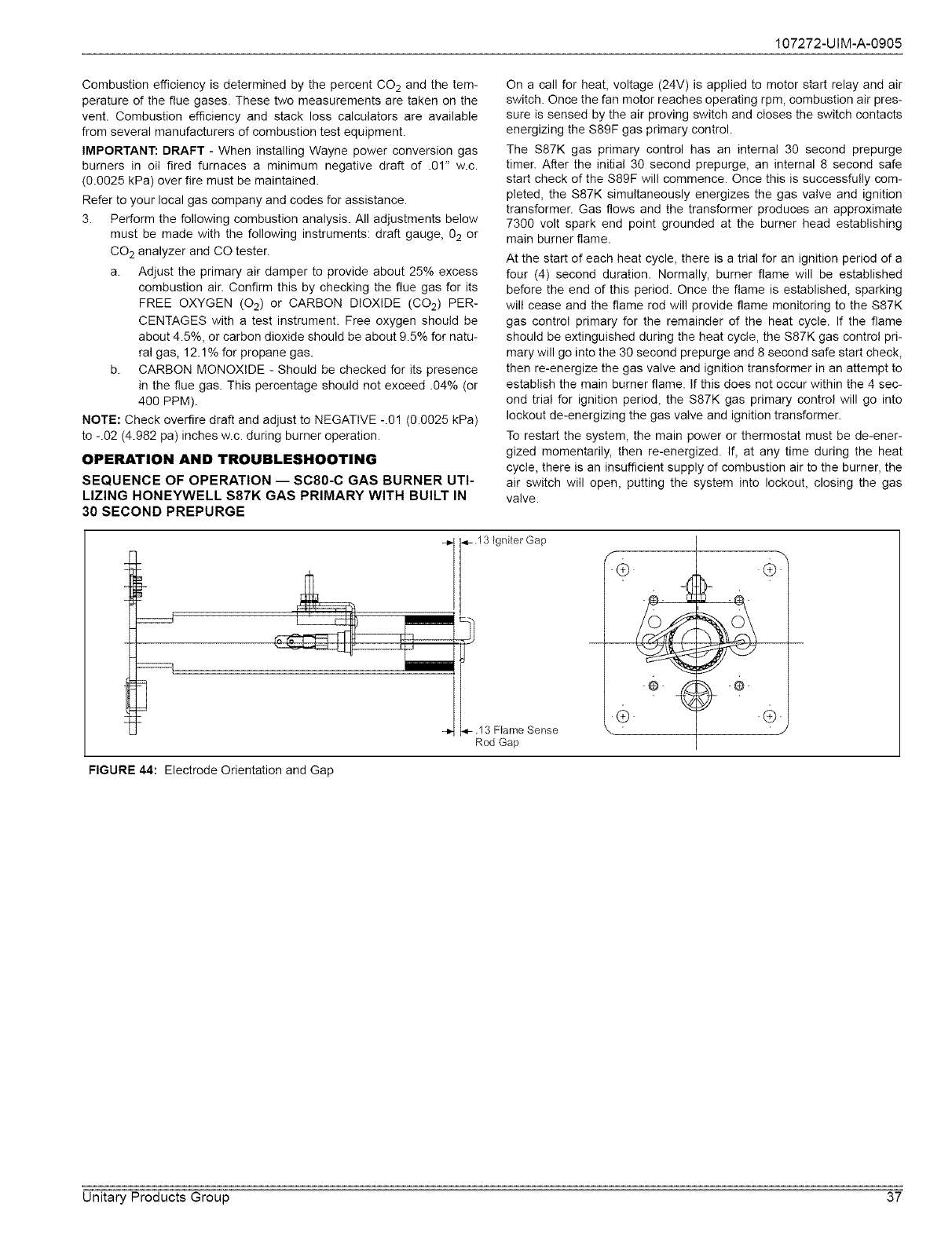
107272-UIM-A-0905
Combustion efficiency is determined by the percent CO 2 and the tem-
perature of the flue gases. These two measurements are taken on the
vent. Combustion efficiency and stack loss calculators are available
from several manufacturers of combustion test equipment.
IMPORTANT: DRAFT - When installing Wayne power conversion gas
burners in oil fired furnaces a minimum negative draft of .01" w.c.
(0.0025 kPa) over fire must be maintained.
Refer to your local gas company and codes for assistance.
3. Perform the following combustion analysis. All adjustments below
must be made with the following instruments: draft gauge, 02 or
CO 2 analyzer and CO tester.
a. Adjust the primary air damper to provide about 25% excess
combustion air. Confirm this by checking the flue gas for its
FREE OXYGEN (02) or CARBON DIOXIDE (CO2) PER-
CENTAGES with a test instrument. Free oxygen should be
about 4.5%, or carbon dioxide should be about 9.5% for natu-
ral gas, 12.1% for propane gas.
b. CARBON MONOXIDE - Should be checked for its presence
in the flue gas. This percentage should not exceed .04% (or
400 PPM).
NOTE: Check overfire draft and adjust to NEGATIVE -.01 (0.0025 kPa)
to -.02 (4.982 pa) inches w.c. during burner operation.
OPERATION AND TROUBLESHOOTING
SEQUENCE OF OPERATION -- SC80-C GAS BURNER UTI-
LIZING HONEYWELL S87K GAS PRIMARY WITH BUILT IN
30 SECOND PREPURGE
On a call for heat, voltage (24V) is applied to motor start relay and air
switch. Once the fan motor reaches operating rpm, combustion air pres-
sure is sensed by the air proving switch and closes the switch contacts
energizing the $89F gas primary control.
The S87K gas primary control has an internal 30 second prepurge
timer. After the initial 30 second prepurge, an internal 8 second safe
start check of the S89F will commence. Once this is successfully com-
pleted, the S87K simultaneously energizes the gas valve and ignition
transformer. Gas flows and the transformer produces an approximate
7300 volt spark end point grounded at the burner head establishing
main burner flame.
At the start of each heat cycle, there is a trial for an ignition period of a
four (4) second duration. Normally, burner flame will be established
before the end of this period. Once the flame is established, sparking
will cease and the flame rod will provide flame monitoring to the $87K
gas control primary for the remainder of the heat cycle. If the flame
should be extinguished during the heat cycle, the $87K gas control pri-
mary will go into the 30 second prepurge and 8 second safe start check,
then re-energize the gas valve and ignition transformer in an attempt to
establish the main burner flame. If this does not occur within the 4 sec-
ond trial for ignition period, the S87K gas primary control will go into
lockout de-energizing the gas valve and ignition transformer.
To restart the system, the main power or thermostat must be de-ener-
gized momentarily, then re-energized. If, at any time during the heat
cycle, there is an insufficient supply of combustion air to the burner, the
air switch will open, putting the system into lockout, closing the gas
valve.
<-.13 Igniter Gap
..13 FIame Sense
Rod Gap
FIGURE 44: Electrode Orientation and Gap
Unitary Products Group 37
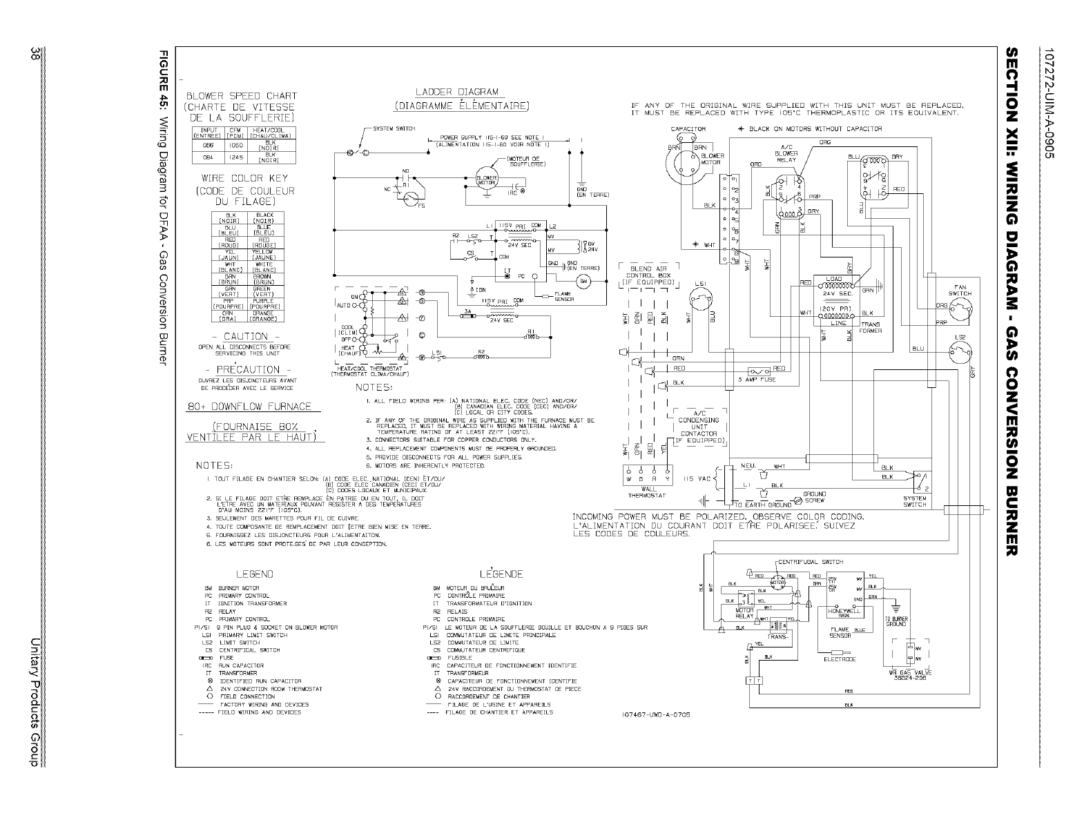
6_
C
po
m
01
B
>
J
©
©
©
<
@
03
3
@
BLOWER SPEED CHART
(CHARTE DE VITESSE
DE LA SOUFFLERIE)
WIRE COLOR KEY
(CODE DE COULEUR
DU FILAGE)
BLACK
(NOIR)
BLUE
[BLEU) [BLEU)
RED RED
IROUG} [ROUGE)
YELLOW
{JAUNE}
WHITE
[BLANC) [BLANC)
BRN BROWN
[BRUN} [BRUN)
GRN GREEN
(VERT} {VERT)
PRP PURPLE
{POURPRE] {POURPRE[
ORN ORANGE
(ORA} {ORANGE)
CAUTION
OPEN ALL DISCONNECTS BEFORE
SERVICING THIS UNIT
PRE'CAUTION
OUVREZ LES DISJONCTEURS AVANT
DE PROCEDER AVEC LE SERVICE
80+ DOWNFLOW FURNACE
(FOURNAISE BOX
VENTILEE PAR LE HAUTI
NOTES=
I TOUT F[LAGE EN CHANTIER SELON: CA[ CODE ELEC .NATIONAL (CEN[ ET/OU/
/_/CODEELECCA.ADENCOEC_ET_OUJ
CODES LOCAUX ET MUNIC[PAUX
Z. S[ LE F[LABE DOlT ET_E REMPLACE EN P_TRIE OU EN TOUT, [L DOIT
L'ETRE AVEC UN MATER[AUX POUVANT RESISTER A DES TEMPERATURES
D'AU MO[NS ZZI"F (105"C).
3, SEULEMENT DES MARETTES POUR FIE DE CUIVRE
#. TOUTE COMPOSANTE DE REMPLACEMENT DOlT [ETRE BEN M[SE EN TERRE.
5 FOURN[SSEZ LE£ D[SJONCTEURS POUR L'AL[MENTAITON.
6, LES MOTEURS SONT PROTE,GES DE PAR LEUR CONCEPTION.
LADDER DIAGRAM
(DIAGRAMME ELEMENTAIRE) IF ANY OF THE ORIGINAL WIRE SUPPLIED WITH THIS UNIT MUST BE REPLACED,
IT MUST BE REPLACED WITH TYPE IO5'C THERMOPLASTIC OR ITS EQUIVALENT.
ee BLACK ON MOTORS WITHOUT CAPACITOR
ORG
LI L2
R2 LSZ MV 1_24v ÷ *.T
GNU GND
II(EN TERRE) F BLEND AIR
(IF EQUIPPED) LSI
_ SEC _1@1@1_1 • •
Ic_k_ i I i i
L __ :3 liarN
HEAT/COOL THERMOSTAT I [_ RED
(THERMOSTAT CLIMA/CHAUF)
NOTES: I III _1 BLK
I. ALL FIELD _[R[NG PER: (A) NATIONAL ELEC. CODE [NEC} AND/OR/
{B) CANADIAN ELEC. CODE (CEC) AND/OR/ I'
[C} LOCAL OR CITY CODESI I I L_ _/_
2. IF ANY OF THE OR[SINAL WIRE AS SUPPLIED WITH THE FURNACE MUST BE i II CONDENSING
UNITREPLACED, IT MUST BE REPLACED WITH WIRING MATERIAL HAVING A I i I
TEMPERATURE RATING OF AT LEAST 221"F (lOS"C). ICONTACTORi
3. CONNECTORS SUITABLE FOR COPPER CONDUCTORS ONLY. I r_i
_I z I a •_F EQUIPPED
41 ALL REPLACEMENT COMPONENTS MUST BE PROPERLY 8ROUNDED. _z _ m m
5. PROVIDE D[SgONNEgT5 FOR ALL POWER SUPPLIES _"
6. MOTORS ARE INHERENTLY PROTECTED
WALL
THERMOSTAT
ORG U
FORIER
BLK
GRaUND
INCOMING POWER MUST BE POLARIZEOI OBSERVE COLOR COOINGI
L'ALIMENTATION DU COURANT DOIT E_RE POLARISEE[ SUIVEZ
LES CODES DE COULEURS.
SYSTEM
SWITCH
LEGEND
BM BURNER MOTOR
PC PRIMARY CONTROL
IT IGNITION TRANSFORMER
R2 RELAY
PC PRIMARY CONTROL
PI/SI 9 PIN PLUG &SOCKET ON BLOWER MOTOR
LSI PRIMARY LIMIT S_ITCH
LS2 LIMIT SWITCH
CS CENTR[FICAL SWITCH
FUSE
IRC RUN CAPACITOR
IT TRANSFORMER
@ IDENTIFIED RUN CAPACITOR
2#V CONNECTION ROOM THERMOSTAT
0 FIELD CONNECTION
FACTORY WIRING AND DEVICES
FIELD WIRING AND DEVICES
LE'GENBE
BM MOTEUR DU BRU_EUR
pC CONTRO_LE pRIMA[RE
IT
R2
PC
PI/SI
L£1
LS2
CS
IRC
IT
®
0
TRANSFORMATEUR D'[GNITION
RELA[S
CONTROLE PR[MAIRE
LE MOTEURDE LA SOUFFLER[E DOUILLE ET BOUCHONA 9 P[OES BUR
COMMUTATEURDE LIM[TE PR[NC[PALE
COMMUTATEURDE LIM[TE
COMMUTATEURCENTRIF[QUE
FUSIBLE
CAPACITEUR DE FONCT[ONNEMENT [DENT[FIE
TRANSFORMEUR
CAPACITEUR DE FONCT[ONNEMENT [DENTIFIE
2¢V RAgCORDEMENT DU THERMOSTAT DE PIECE
RACCORDEMENTDE CHANTER
F[LABE DE L'USiNE ET APPARE[LS
FILAGE DE CHANTIER ET APPARE[LS 107#67 UWO A 0705
WR GAS VALVE
BLK
,>
g
o
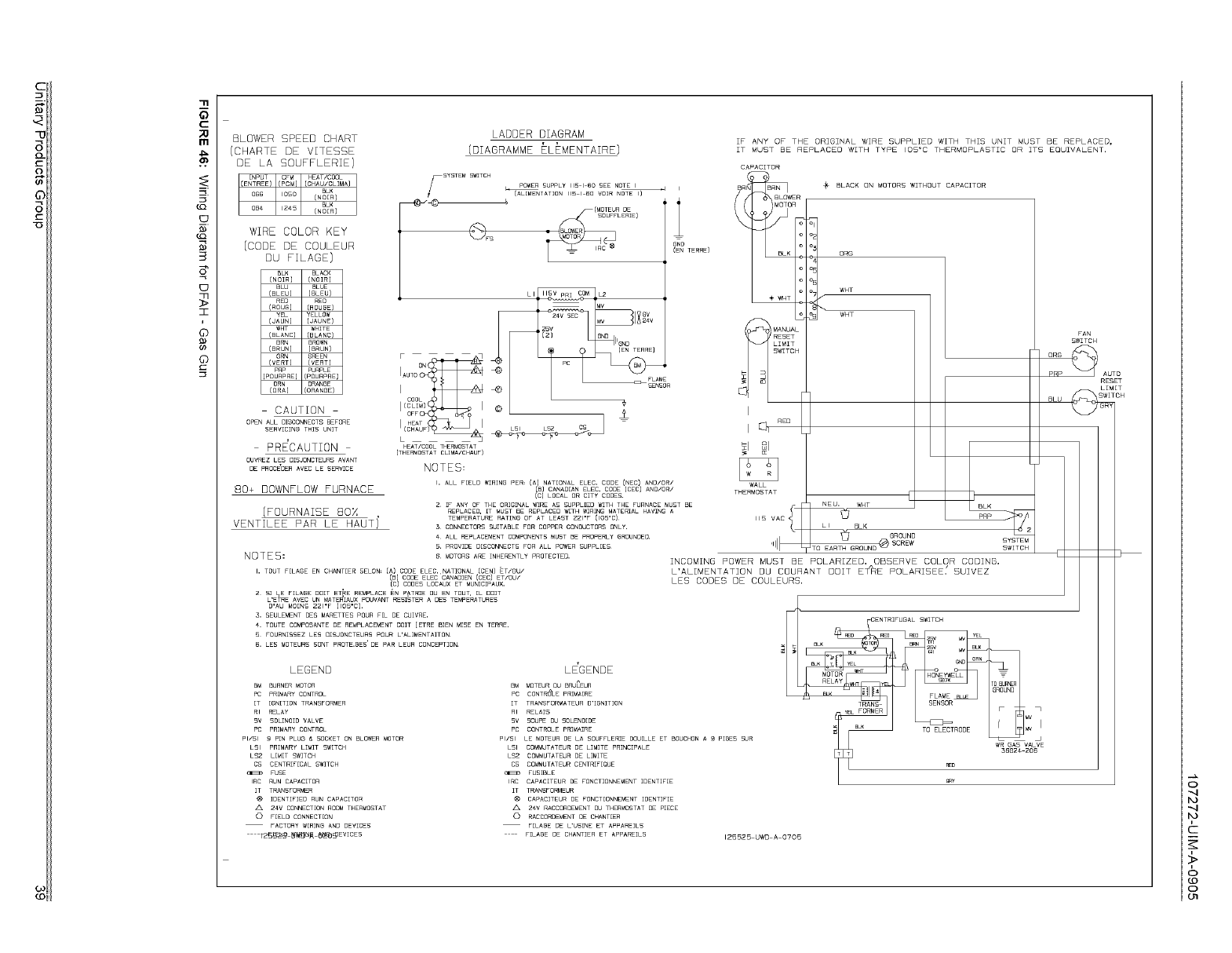
11
5
C
m
tQ
_o.
B)
3
:I
J
©
B)
©
BLOWER SPEED CHART
(CHARTE DE VITESSE
DE LA SOUFFLERIE)
WIRE COLOR KEY
{CODE DE COULEUR
DU FILAGE)
BLACK
(NOIR}
BLUE
(BLEU) (BLEU)
RED
(ROUGE}
YELLOW
(JAUN) (JAUNE)
WHT WHITE
(BLANC) (BLANC)
BROWN
{BRUN)
GREEN
! VpER_T) (VERT)
PURPLE
:POURPRE) (POURPRE)
ORN ORANBE
CORAl CORANGEI
CAUTION
OPEN ALL DISCONNECTS BEFORE
SERVICINB THIS UNIT
PRE'CAUTION
OUVREZ LES DISJONCTEURS AVANT
DE PROCEDER AVEC LE SERVICE
80+ DOWNFLOW FURNACE
(FOURNAISE 80X
VENTILEE PAR LE HAUT I
NOTES=
LADDER DIAGRAM
(DIAGRAMME ELEMENTAIRE)
FSYSTEM POWER SUPPLY 115 I 6O SEE NOTE I
S_]TCH
_" (ALIMENTATIeN 115 I 60 VOIR NOTE I)
4
L I L2
M_ GV
IX24v
8ND IIGNo
4_} SENSOR
L 3
HEAT/COOL THERMOSTAT
[THERMOSTAT CLIMA/CHAUF)
NOTES:
I. aLL FIELD WIRING PER, (a) NATIONAL ELEC. CODE (NEC) aND/OR/
(B) CANAO[AN ELEC. COOE (CEC) ANO/OR/
(C) LOCAL OR CiTY CODES,
2 IF ANY OF THE ORIGINAL WIRE AS SUPPLED WITH THE FURNACE MUST BE
REPLACEO, IT MUST BE REPLACEO WITH WIRING MATERIAL HAVING A
TEMPERATUREaATINGOr ATLEAST221"F (105'C)
5 CONNECTORS £UITABLE FOR COPPER CONDUCTORS ONLY
4 ALL REPLACEMENTCOMPONENTSMUSTBE PnOPERLYGROUNOED.
5. PROVIDE D[SCONNECT£ FOR ALL POWER SUPPLIES
I
GNO
(EN TERRE)
IF ANY OF THE ORIGINAL WIRE SUPPLIED WITH THIS UNIT MUST BE REPLACED•
IT MUST BE REPLACED WITH TYPE I©5_6 THERMOPLASTIC OR ITS EQUIVALENT.
CAPACITOR
BLACK ON MOTORS WITHOUT CAPACITOR
ORG
WHT
WHT
BLK
GROUND SYSTEM
EARTH GROUND _SCREw SWITCH
& MOTORSARE iNHERENTLY PROTECTED.
INCOMING POWER MUST BE POLARIZED. OBSERVE COLOR CODING.
I. TOUT F[LAGE EN CHANT[ER 5ELON: (A) CODE ELEC. NATIONAL (FEN} ET/OU/ L'ALIMENTATION DU COURANT DOIT ET_RE POLARISEE. SUIVEZ
LES CODES DE COULEURG.
CENTRIFUGAL SWITCH
REO _L
BL_
LE'GENDE _
MOTEUR DU BRU_EUR
CONTR_LE PRIMA{RE
TRANSFORMATEUR D'[BNITION _ TRANS
RELAIS YEL FORMER WV 7
SOUPE DU SOLENOIDE /
CONTROLE PRIMAIRE
LE MOTEUR DE LA SOUFFLERIE DOU[LLE ET BOUCHON A 9 P[GES SUR
CAPACITEuRCOMMUTATEuRCOMMUTATEURFus[BLEDECENTRIF[QuEDEFoNCTIONNEMENTL[MITEIDENT[FE _ _D:i W_3662¢G_ ......206
TRANSFORMEUR
CAPACITEUR DE FONCT[ONNEMENT iDENTIFIE
2€V RACCORDEMENT DU THERMOSTAT DE PIECE
RACCOROEMENT DE CHANTER
F[LAGE DE L'US[NE ET APPAREILS
F[LAGE DE CHANTIER ET APPAREILS 125525 UWD A 0705
B CODE ELEC CANADIEN (CEC) ET/OU/
14........................
• Sl _E rILA_E DGIT ET_E _M_ _ _ _ _ _, _ _
_ET_E A_EC U_ _ATE_AU× POU_A_T RE_TE_ _ DE_ TE_PE_ATU_E_
D_AU M_ _ I_CI_
_ _EU_EME_T DE_ _ETTE_ _U_ _ DE _U_E_
_ TOUTE COMPO_A_TE DE _EM_ACEME_T _O_T [ET_E _E_ M_E E_ TER_E_
_U_E_ _E_ O_TEU_ _OUR _A_E_T_T_
_ _E_ _OTEUR_ _O_T P_OTE_E_ _ _E PA_ _EU_ CO_CE_T_O_
LEGEND
BM BURNER MOTOR BM
PC PRIMARY CONTROL PC
[T IGNITION TRANSFORMER IT
RI RELAY RI
SV SBLINO[D VALVE SV
PC PRIMARY CONTROL PC
PI/SI 9 PIN PLUG & SOCKET ON BLO_R MOTOR PI/SI
LSI PRIMARY LiMiT SWITCH LSI
LS2 L[_[T SWITCH LS2
CS CENTR[F[CAL SWITCH CS
FUSE
IRC RUN CAPACITOR IRC
IT TRANSFORMER IT
IDENTIFIED RUN CAPACITOR
24V CONNECT{ON ROOM THERMOSTAT
0 FIELD CONNECT{ON 0
FACTORY WIRING AND DEVICES
FAN
SWITCH
ORB
PRP AUTO
RESET
LIM
BLU _SW[1
o
,12
c
,>
g
g
NOTES
Subject to change without notice. Printed in U.S.A.
Copyright st by York International Corp. 2005. All rights reserved.
Unitary
Product
Group
5OO5
York
Drive
107272-UIM-A-0905
Supersedes: 035-16393-001 Rev. B (0304)
Norman
OK
73069
