COLEMAN / EVCON IND. Air Conditioner/heat Pump(outside Unit) Manual L0611519
User Manual: COLEMAN COLEMAN / EVCON IND. Air conditioner/heat pump(outside unit) Manual COLEMAN / EVCON IND. Air conditioner/heat pump(outside unit) Owner's Manual, COLEMAN / EVCON IND. Air conditioner/heat pump(outside unit) installation guides
Open the PDF directly: View PDF ![]() .
.
Page Count: 8
R-22
OUTDOOR SPLIT-SYSTEM
AIR CONDITIONING
MODELS: 13 SEER - ERCQ SERIES
2 TO 4 TONS
Certification applies only ISO 9001
when the complete Certified Quality
system ls listed Management System
with ARI
LIST OF SECTIONS
GENERAL .............................................. 1 ELECTRICAL CONNECTIONS .............................. 5
SAFETY ................................................ 1 INDICATIONS OF PROPER OPERATION ..................... 6
UNIT INSTALLATION ..................................... 2
LIST OF FIGURES
Typical Installation ........................................ 2
Oil Trap ................................................ 3
Minimum Suction Line Form ................................ 3
Excess Tube ............................................ 3
Installation dVapor Line ................................... 4
Quick Connect Refrigerant Line .............................. 4
Ouick Connect Coupling .................................... 4
Outdoor Unit Control Box ................................... 5
Typical Furnace Thermostat Wiring ........................... 5
Typical Field Wiring (Air Handler/Electrical Heat) ................ 6
LIST OF TABLES
Application Limitations ..................................... 2
SECTION h GENERAL
These outdoor condensing units are designed to be connected to a
matching UPG indoor coil. They are equipped with a filter-drier located
in the liquid line.
Units with quick-connect coupling connections are factory charged with
refrigerant to be matched with the appropriate precharged line set, and
UPG indoor soil.
The outdoor unit is designed to be placed near the perimeter of the
home, typically alongside or at the back of the home, remote from the
indoor coil. The outdoor unit has been factory run-tested and all compo-
nents of the system are ready for easy, immediate installation.
SECTION Ih SAFETY
[_ This is a safety alert symbol. When you see this symbol on
labels or in manuals, be alert to the potential for personal
injury.
Understand and pay particular attention to the signal words DANGER,
WARNING, or CAUTION.
DANGER indicates an imminently hazardous situation, which, if not
avoided, will result in death or serious injury.
WARNING indicates a potentially hazardous situation, which, if not
avoided could result in death or serious injury.
CAUTION indicates a potentially hazardous situation, which, if not
avoided may result in minor or moderate iniurv. It is also used to
alert against unsafe practices and hazards involving only property dam-
age
AWARNING
Improper installation may create acondition where the operation of
the product could cause personal injury or property damage.
Improper installation, adjustment, alteration, service or mainte-
nance can cause injury or property damage. Refer to this manual
for assistance or for additional information, consult a qualified con-
tractor, instafler or service agency.
A CAUTION
This product must be installed in strict compliance with the
enclosed installation instructions and any applicable local, state,
and national codes including, but not limited to building, electrical,
and mechanical codes.
INSPECTION
As soon as a unit is received, it should be inspected for possible dam-
age during transit. If damage is evident, the extent of the damage
should be noted on the carrieCs delivery receipt. A separate request for
inspection by the carrier's agent should be made in writing. See Local
Distributor for more information.
LIMITATIONS
The unit should be installed in accordance with all National, State and
Local Safety Codes and the limitations listed below:
1. Limitations for the indoor unit, coil, and appropriate accessories
must also be observed.
2. The outdoor unit must not be installed with any duct work in the air
stream. The outdoor fan is the propeller type and is not designed
to operate against any additional external static pressure.
172266-UIM-A-0106
172266-UIM-A-0106
3. The maximum and minimum conditions for operation must be
observed to assure a system that will give maximum performance
with minimum service.
TABLE 1: Application Limitations
4.
Ambient Air Temperature Air Temperature on
on Outdoor Coil Indoor Coil
Min. DB |Max. DB Min. WB | Max. WB
50 °F T !15 °F 57 °F T 72 °F
The unit should not be operated at outdoor temperatures below
50 ° F without an approved low ambient operation accessory kit
installed.
SECTION IIh UNIT INSTALLATION
LOCATION
Before starting the installation: select and check the suitability of the
location for both the indoor and outdoor unit. Observe all limitations and
clearance requirements.
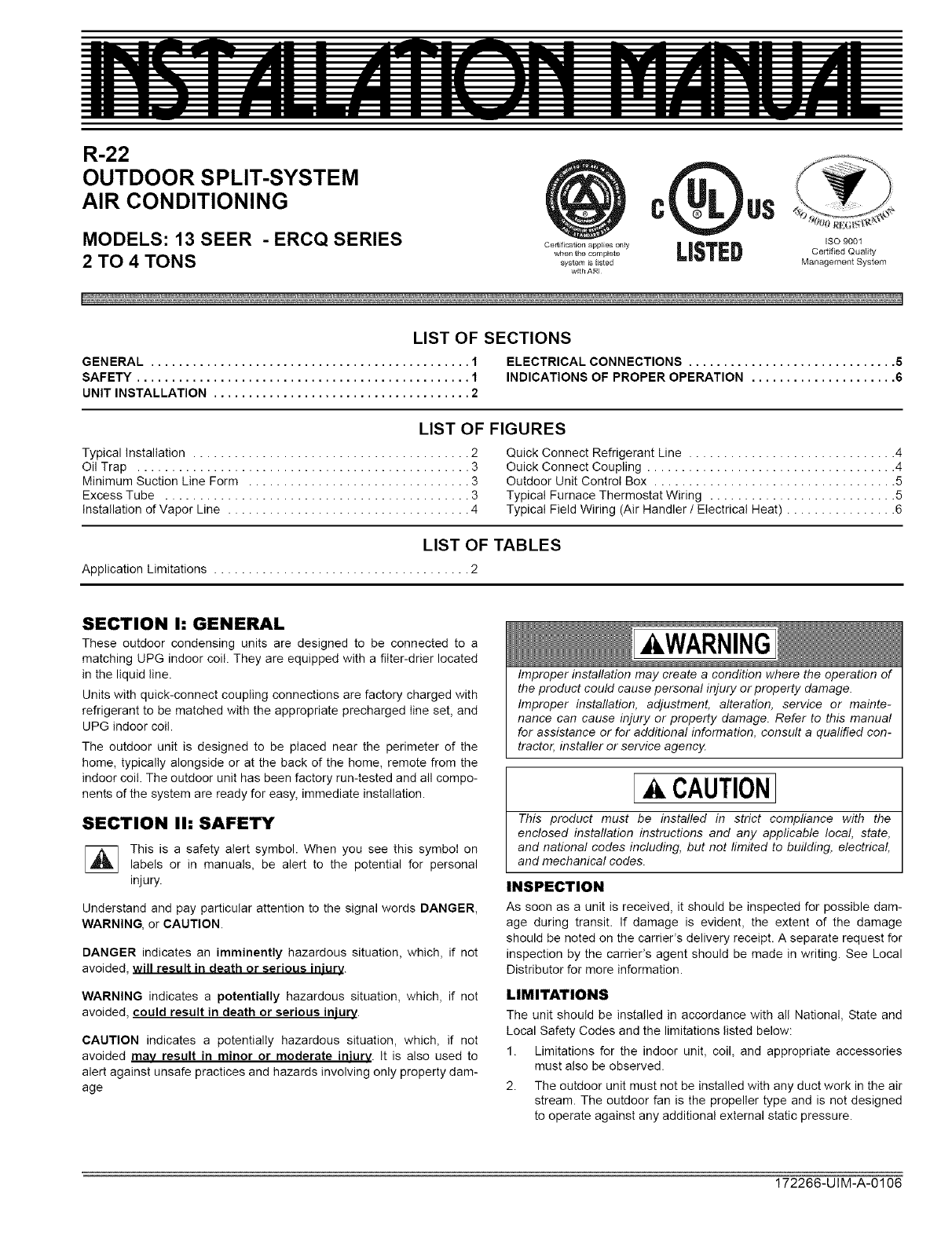
The outdoor unit must have sufficient clearance for air entrance to the
condenser coil, air discharge, and service access. See Figure !.
NOTE: For multiple unit installations, units must be spaced a minimum
of !8 inches apart (coil face to coil face).
If the unit is to be installed on a hot sun exposed roof or a black-topped
ground area, the unit should be raised sufficiently above the roof or
ground to avoid taking the accumulated layer of hot air into the outdoor
unit.
Provide an adequate structural support.
ADD-ON REPLACEMENT/RETROFIT
The following steps should be performed in order to insure proper sys-
tem operation and performance.
1. Change-out the indoor coil, if required, to an approved R-22 coil/
condensing unit combination with the appropriate metering device.
2. If the outdoor unit is being replaced due to a compressor burnout,
then installation of a 100% activated alumina suction-line filter
drier in the suction-line is required, in addition to the factory
installed liquid-Iine drier. Operate the system for 10 hours. Monitor
the suction drier pressure drop. If the pressure drop exceeds 3
psig, replace both the suction-Iine and liquid-line driers. After a
total of 10 hours run time where the suction-line pressure drop has
not exceeded 3 psig, replace the liquid line drier, and remove the
suction-line drier. Never leave a suction-Iine drier in the system
longer than 50 hours of run time.
CLEARANCE
10"CLEARANCE
COILAREA _ j_ ....
/.J"
J
\
MINIMUM 24" SERVICE ACCESS
CLEARANCE ON ONE SIDE
CONTROL WEATHERPROOF
ACCESS DISCONNECT
PANEL SWITCH
THERMOSTAT TO FURNACE OR
AIR HANDLER
TERMINAL BLOCK
NEC CLASS 1 WIRING
NEC CLASS 2 WIRING
TO INDOOR COIL
NOTE: ALL OUTDOOR WIRING
FIGURE 1: Typical Installation
GROUND INSTALLATION
The unit should be installed on a solid base that is 2" above grade and
will not shift or settle, causing strain on the refrigerant lines and possible
leaks. Maintain the clearances shown in Figure 1 and install the unit in a
level position. The base pad should not come in contact with the foun-
dation or side of the structure because sound may be transmitted to the
residence.
The length of the refrigerant tubing between the outdoor unit and indoor
coil should be as short as possible to avoid capacity and efficiency
losses. Excessive spacing of the outdoor unit from the home can result
in the refrigerant lines being restricted by trampling or being punctured
by lawn mowers. Locate the outdoor unit away from bedroom windows
or other rooms where sound might be objectionable.
SEAL OPENING(S) WITH
PERMAGUM OR EQUIVALENT
POSSIBLE OUTDOOR THERMOSTAT KIT LOCATIONS
(UNIT MOUNTING NOT AVAILABLE ON ALL MODELS)
Adverse effects of snow or sleet accumulating on the outdoor coiI can
be eliminated by placing the outdoor unit where the prevailing wind
does not blow across the unit. Trees, shrubs, corners of buildings, and
fences standing off from the coil can reduce capacity Ioss due to wind
chill effect.
Provide ample clearance from shrubs to allow adequate air to pass
across the outdoor coil without leaves or branches being pulled into the
coil.
ROOF INSTALLATION
When installing units on a roof, the structure must be capable of sup-
porting the total weight of the unit, including a pad, lintels, rails, etc.:
which should be used to minimize the transmission of sound or vibra-
tion into the conditioned space.
2 Unitary Products Group
172266-UIM-A-0106
LIQUID LINE FILTER-DRIER
The air conditioning unit's copper spun filter/dryer is located on the liq-
uid line.
NOTE: Replacements for the liquid line drier must be exactlv the same
as marked on the original factory drier. See Source 1 for O.E.M.
replacement driers.
CAUTION
Failure to do so or using a substitute drier or a granular type may
result in damage to the equipment.
PIPING CONNECTIONS
The outdoor condensing unit must be connected to the indoor evapora-
tor coil using field supplied refrigerant grade (ACR) copper tubing that is
internally clean and dry. Units should be installed only with the tubing
sizes for approved system combinations as specified in tabular data
sheet. The charge given is applicable for total tubing lengths up to 15
feet. See Application Data Part Number 036-61920-000 for installing
tubing of longer lengths and elevation differences.
NOTE: Using a larger than specified line size could result in oil return
problems. Using too small a line will result in loss of capacity and other
problems caused by insufficient refrigerant flow. SloPe horizontal vauor
lines at least !" every 20 feet toward the outdoor unit to facilitate proper
oil return.
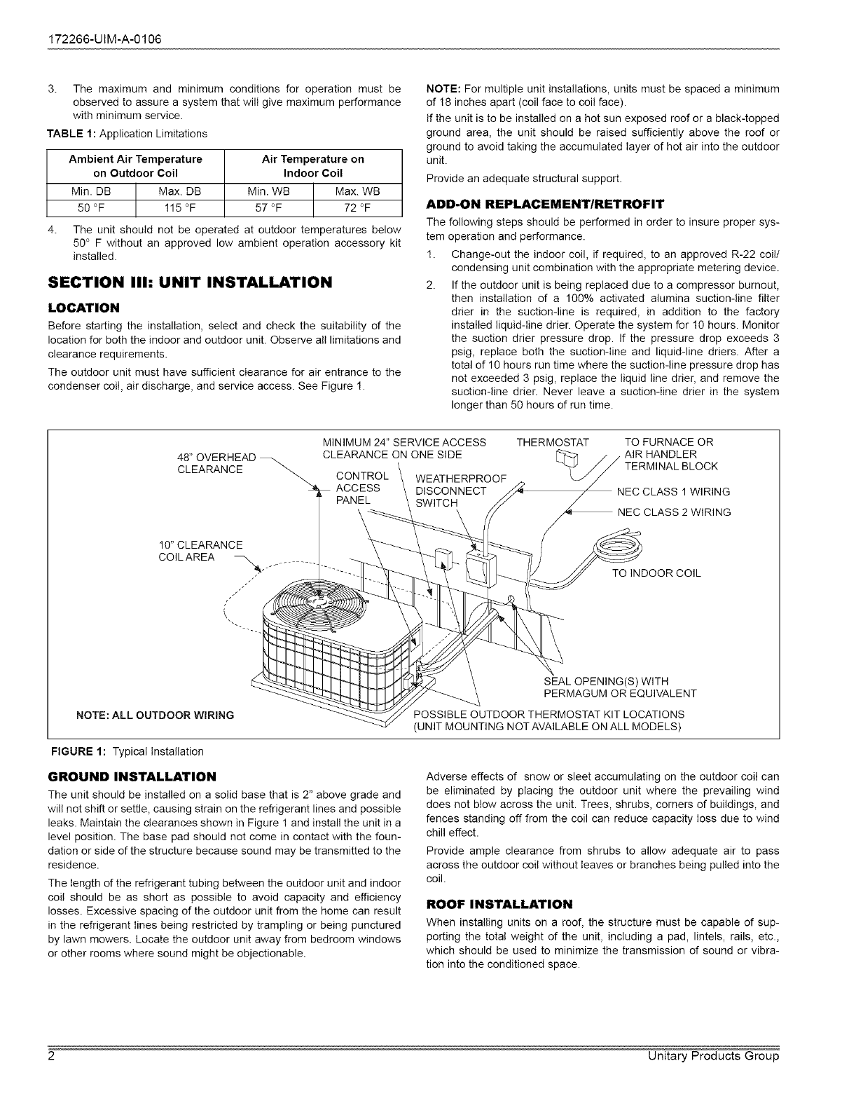
OIL TRAPPING
When the outdoor unit is above the indoor coil oil trapping is necessary.
An oil trap should be provided for every 20 ft. of rise. See Figure 2.
OUTDOOR COIL
I
, ooo i I +-
CO,L o;t.
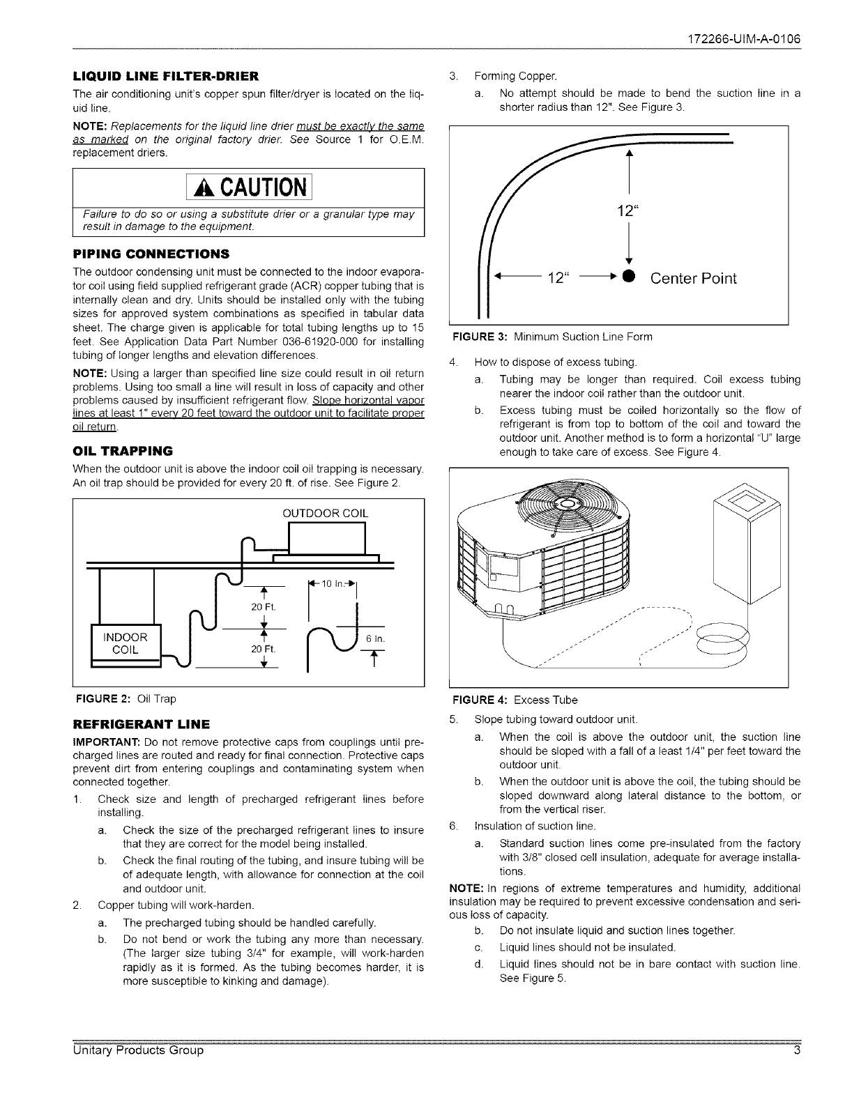
3. Forming Copper.
a. No attempt should be made to bend the suction Iine in a
shorter radius than 12". See Figure 3.
12" _• Center Point
FIGURE 3: Minimum Suction Line Form
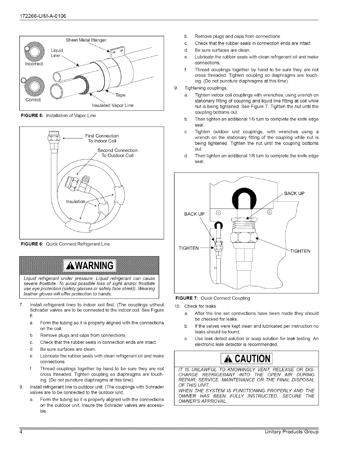
4. How to dispose of excess tubing.
a. Tubing may be longer than required. Coil excess tubing
nearer the indoor coil rather than the outdoor unit.
b. Excess tubing must be coiled horizontally so the flow of
refrigerant is from top to bottom of the coil and toward the
outdoor unit. Another method is to form a horizontal "U" large
enough to take care dexcess. See Figure 4.
FIGURE 2: Oil Trap
REFRIGERANT LINE
IMPORTANT: Do net remove protective caps from couplings until pre-
charged lines are routed and ready for final connection. Protective caps
prevent dirt from entering couplings and contaminating system when
connected together.
1. Check size and length of precharged refrigerant lines before
installing.
a. Check the size of the precharged refrigerant lines to insure
that they are correct for the model being installed.
b. Check the final routing of the tubing, and insure tubing will be
of adequate length, with allowance for connection at the coil
and outdoor unit.
2. Copper tubing will work-harden.
a. The precharged tubing should be handled carefully.
b. Do not bend or work the tubing any more than necessary.
(The larger size tubing 3/4" for example, will work-harden
rapidly as it is formed. As the tubing becomes harder, it is
more susceptible to kinking and damage).
FIGURE 4: Excess Tube
5. Slope tubing toward outdoor unit.
a. When the coil is above the outdoor unit, the suction line
should be sloped with a fall of a least 1/4" per feet toward the
outdoor unit.
b. When the outdoor unit is above the coil, the tubing should be
sloped downward along lateral distance to the bottom, or
from the vertical riser.
6. insulation of suction line.
a. Standard suction lines come pre-insulated from the factory
with 3/8" closed ceil insulation, adequate for average installa-
tions.
NOTE: In regions of extreme temperatures and humidity, additional
insulation may be required to prevent excessive condensation and seri-
ous loss of capacity.
b. Do not insulate liquid and suction lines together.
c. Liquid lines should not be insulated.
d. Liquid lines should not be in bare contact with suction line.
See Figure 5.
Unitary Products Group 3
172266-UIM-A-0106
Incorrect
Sheet Metal Hanger
Liquid
Line
]'ape
Correct
Insulated Vapor Line
FIGURE 5: Installation of Vapor Line
First Connection
To Indoor Coil
Second Connection
To Outdoor Coil
FIGURE 6: Quick Connect Refrigerant Line
,&.WARNING
Liquid refrigerant under pressure. Liquid refrigerant can cause
severe frostbite. To avoid possible loss of sight and/or frostbite
use eye protection (safety glasses or safety face shield). Wearing
leather gloves will offer protection to hands.
7. Install refrigerant lines to indoor coil first. (The couplings without
Schrader valves are to be connected to the indoor coil. See Figure
6.
a. Form the tubing so it is properly aligned with the connections
on the coil.
b. Remove plugs and caps from connections.
c. Check that the rubber seals in connection ends are intact.
d. Be sure surfaces are clean.
e. Lubricate the rubber seals with clean refrigerant oil and make
connections.
f. Thread couplings together by hand to be sure they are not
cross threaded. Tighten coupling so diaphragms are touch-
ing. (Do not puncture diaphragms at this time).
8. Install refrigerant line to outdoor unit. (The couplings with Schrader
valves are to be connected to the outdoor unit.
a. Form the tubing so it is properly aligned with the connections
on the outdoor unit. insure the Schrader valves are accessi-
ble.
b. Remove plugs and caps from connections.
c. Check that the rubber seals in connection ends are intact.
d. Be sure surfaces are clean.
e. Lubricate the rubber seals with clean refrigerant oil and make
connections.
f. Thread couplings together by hand to be sure they are not
cross threaded. Tighten coupling so diaphragms are touch-
ing. (Do not puncture diaphragms at this time).
Tightening couplings.
a. Tighten indoor coil couplings with wrenches; using wrench on
stationary fitting of coupling and liquid line fitting at coil while
nut is being tightened. See Figure 7. Tighten the nut until the
coupling bottoms out.
b. Then tighten an additional 1/6 turn to complete the knife edge
seal.
c. Tighten outdoor unit couplings, with wrenches using a
wrench on the stationary fitting of the coupling while nut is
being tightened. Tighten the nut until the coupling bottoms
out.
d. Then tighten an additional 1/6 turn to complete the knife edge
seal.
BACK UP
\
UP
TIGHTEN-- "-TIGHTEN
FIGURE 7: Ouick Connect Coupling
10. Check for leaks.
a. After the line set connections have been made they should
be checked for leaks.
b. If the valves were kept clean and lubricated per instruction no
leaks should be found.
c. Use leak detect solution or soap solution for leak testing. An
electronic leak detector is recommended.
CAUTION
IT IS UNLAWFUL TO KNOWINGLY VENT, RELEASE OR DIS-
CHARGE REFRIGERANT INTO THE OPEN AIR DURING
REPAIR, SERVICE, MAINTENANCE OR THE FINAL DISPOSAL
OF THIS UNIT
WHEN THE SYSTEM IS FUNCTIONING PROPERLY AND THE
OWNER HAS BEEN FULLY INSTRUCTED, SECURE THE
OWNER'S APPROVAL.
4 Unitary Products Group
172266-UIM-A-0106
SECTION IV: ELECTRICAL CONNECTIONS
GENERAL INFORMATION & GROUNDING
Check the electrical supply to be sure that it meets the values specified
on the unit nameplate and wiring label.
Power wiring, control (low voltage) wiring, disconnect switches and over
current protection must be supplied by the installer. Wire size should be
sized per NEC requirements.
CAUTION
All field wiring must USE COPPER CONDUCTORS ONLY and be
in accordance with Local National Fire, Safety & Electrical Codes.
This unit must be grounded with a separate ground wire in accor-
dance with the above codes.
The complete connection diagram and schematic wiring label is located
on the inside surface of the unit service access panel.
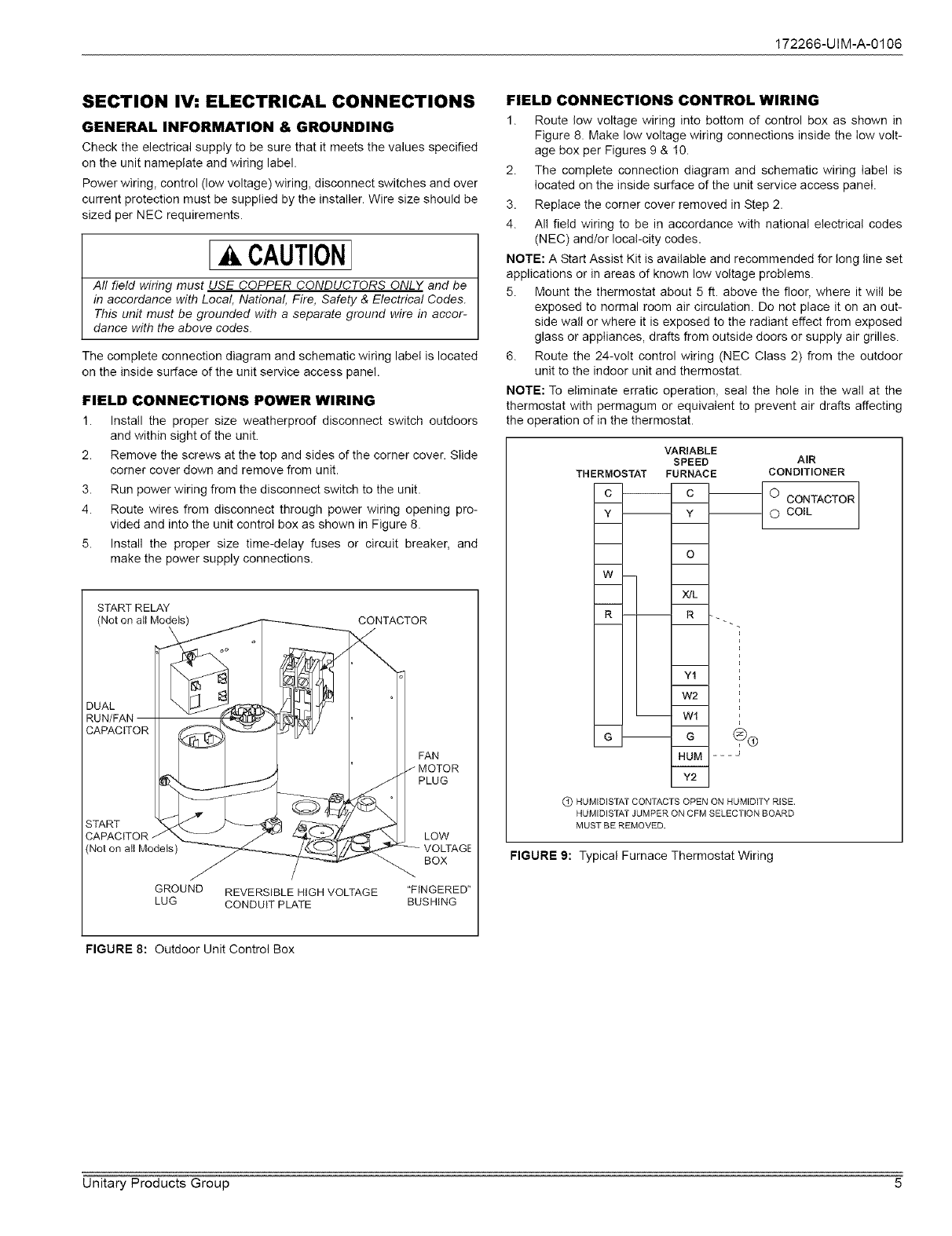
FIELD CONNECTIONS POWER WIRING
1. Install the proper size weatherproof disconnect switch outdoors
and within sight of the unit.
2. Remove the screws at the top and sides of the corner cover. Slide
corner cover down and remove from unit.
3. Run power wiring from the disconnect switch to the unit.
4. Route wires from disconnect through power wiring opening pro-
vided and into the unit control box as shown in Figure 8.
5. Install the proper size time-delay fuses or circuit breaker, and
make the power supply connections.
1START RELAY
(Not on aIt Models) CONTACTOR
DUAL
FAN
PLUG
LOW
) VOLTAGE
BOX
GROUND REVERSIBLE HIGH VOLTAGE "FINGERED"
LUG CONDUIT PLATE BUSHING
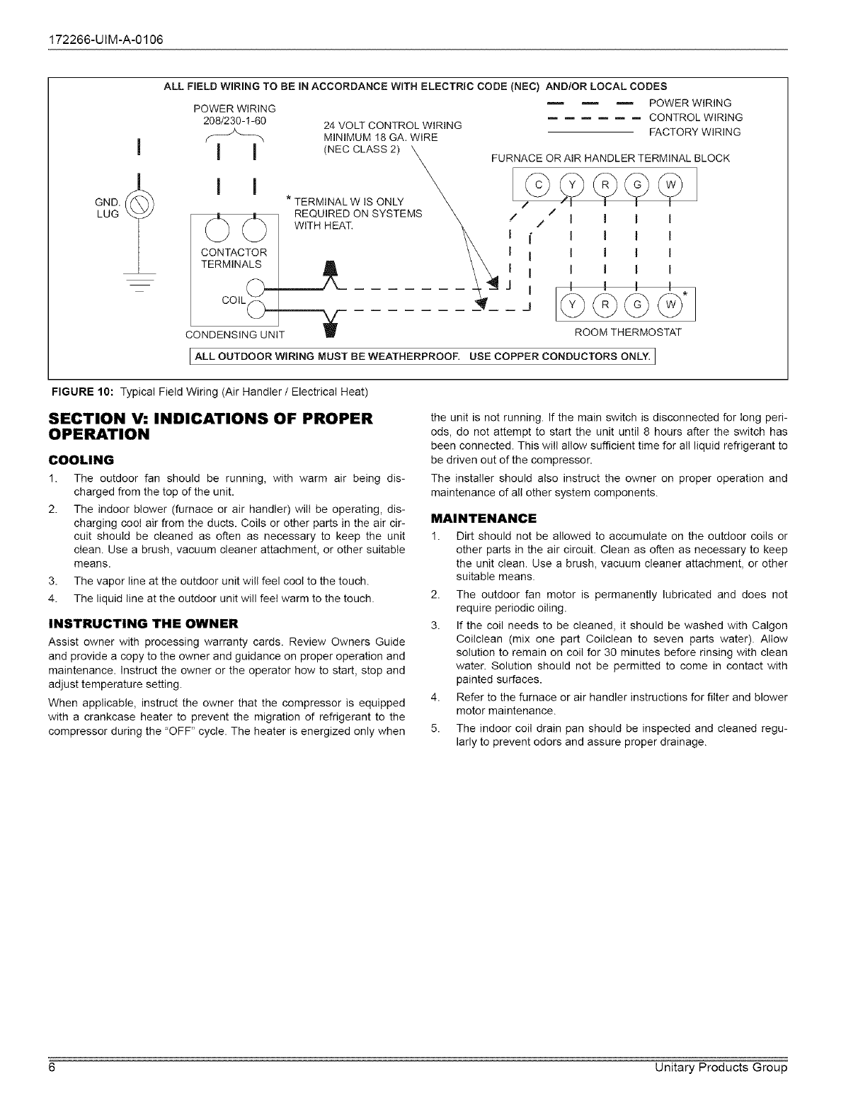
FIELD CONNECTIONS CONTROL WIRING
1. Route low voltage wiring into bottom of control box as shown in
Figure 8. Make low voltage wiring connections inside the Iow volt-
age box per Figures 9 & 10.
2. The complete connection diagram and schematic wiring label is
located on the inside surface of the unit service access panel.
3. Replace the corner cover removed in Step 2.
4. All field wiring to be in accordance with national electrical codes
(NEC) and/or local-city codes.
NOTE: A Start Assist Kit is available and recommended for long line set
applications or in areas of known low voltage problems.
5. Mount the thermostat about 5 ft. above the floor, where it wilI be
exposed to normal room air circulation. Do not place it on an out-
side wall or where it is exposed to the radiant effect from exposed
glass or appliances, drafts from outside doors or supply air grilles.
6. Route the 24-volt control wiring (NEC Class 2) from the outdoor
unit to the indoor unit and thermostat.
NOTE: To eliminate erratic operation, seal the hole in the watl at the
thermostat with permagum or equivalent to prevent air drafts affecting
the operation of in the thermostat.
VARIABLE
SPEED
THERMOSTAT FURNACE
c
w
HUM - -- J
i
V2
Q HUMIDISTAT CONTACTS OPEN ON HUMIDITY RISE.
HUMIDISTAT JUMPER ON CFM SELECTION BOARD
MUST BE REMOVED.
AIR
CONDITIONER
O CONTACTOR
O COIL
FIGURE 9: Typical Furnace Thermostat Wiring
FIGURE 8: Outdoor Unit Control Box
Unitary Products Group 5
172266-UIM-A-0106
GND.
LUG
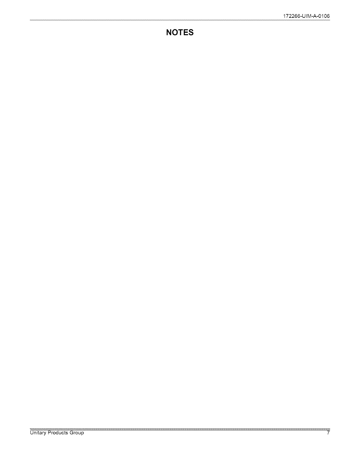
ALL FIELD WIRING TO BE IN ACCORDANCE WITH ELECTRIC CODE (NEC) AND/OR LOCAL CODES
POWER WIRING POWER WIRING
CONTROL WIRING
208/230-1-60 24 VOLT CONTROL WIRING
K--_--_'_ MINIMUM 18 GA, WIRE FACTORY WIRING
I I (NEC CLASS 2) FURNACE OR AiR HANDLER TERMINAL BLOCK
I I I
OO
CONTACTOR
TERMINALS
COIL_
CONDENSING UNIT
*TERMINAL W IS ONLY
REQUIRED ON SYSTEMS
WITH HEAT.
ROOM THERMOSTAT
ALL OUTDOOR WIRING MUST BE WEATHERPROOF. USE COPPER CONDUCTORS ONLY. 1
FIGURE 10: Typical Field Wiring (Air Handler/Electrical Heat)
SECTION V: INDICATIONS OF PROPER
OPERATION
COOLING
1. The outdoor fan should be running, with warm air being dis-
charged from the top of the unit.
2. The indoor blower (furnace or air handler) will be operating, dis-
charging cool air from the ducts. Coils or other parts in the air cir-
cuit should be cleaned as often as necessary to keep the unit
ciean. Use a brush, vacuum cleaner attachment, or other suitable
means.
3. The vapor line at the outdoor unit will feel cool to the touch.
4. The liquid line at the outdoor unit will feet warm to the touch.
INSTRUCTING THE OWNER
Assist owner with processing warranty cards. Review Owners Guide
and provide a copy to the owner and guidance on proper operation and
maintenance. Instruct the owner or the operator how to start, stop and
adjust temperature setting.
When applicable, instruct the owner that the compressor is equipped
with a crankcase heater to prevent the migration of refrigerant to the
compressor during the "OFF" cycle. The heater is energized only when
the unit is not running. If the main switch is disconnected for long peri-
ods, do not attempt to start the unit until 8 hours after the switch has
been connected. This will allow sufficient time for all liquid refrigerant to
be driven out of the compressor.
The installer should also instruct the owner on proper operation and
maintenance of all other system components.
MAINTENANCE
1. Dirt should not be allowed to accumulate on the outdoor coils or
other parts in the air circuit. Clean as often as necessary to keep
the unit clean. Use a brush, vacuum cleaner attachment, or other
suitable means.
2. The outdoor fan motor is permanently lubricated and does not
require periodic oiling.
3. If the coil needs to be cleaned, it should be washed with Calgon
Coilclean (mix one part Coilclean to seven parts water). Allow
solution to remain on coil for 30 minutes before rinsing with clean
water. Solution should not be permitted to come in contact with
painted surfaces.
4. Refer to the furnace or air handler instructions for filter and blower
motor maintenance.
5. The indoor coil drain pan should be inspected and cleaned regu-
larly to prevent odors and assure proper drainage.
6 Unitary Products Group
NOTES
172266-UIM-A-0106
Unitary Products Group 7
Subjecttochangewithoutnotice.PrintedinU.S.A.
Copyright_ byYorkInternationalCorp.2006.Allrightsreserved.
Unitary
Product
Group
5005
York
Drive
172266-UIM-A-0106
Supersedes: Nothing
Norman
OK
73069
