COLEMAN / EVCON IND. Controls And HVAC Accessories Manual L0612103
User Manual: COLEMAN COLEMAN / EVCON IND. Controls and HVAC Accessories Manual COLEMAN / EVCON IND. Controls and HVAC Accessories Owner's Manual, COLEMAN / EVCON IND. Controls and HVAC Accessories installation guides
Open the PDF directly: View PDF ![]() .
.
Page Count: 2
:? 6" :?_ "-- ) 'J-
Z44 , 700 t & ,2,455,-,, 00g
+A{_ APTEV Kg']+S
DIVlPORTANT NOTICE
These instructions are intended for the use of qualified indi-
viduals specially trained and experienced in installation of
this type of equipment and related system components,
Installation and service personnel are required by some
states to be licensed.
Persons not qualified shall not install this equipment or
interpret these instructions.
NOTE
The words "Shall" or "Must" indicate a requirement which is
essential to satisfactory and safe product performance.
The words "Should" or "May" indicate a recommendation
or advice which is not essential and not required but which
may be useful or helpful.
WARNINGJ
1. IMPROPER INSTALLATION OR SERVICE MAY DAM-
AGE EQUIPMENT, CAN CREATE A HAZARD AND
WILL VOID THE WARRANT_.
2. WHEN WORKING WITH HIGH PRESSURE GASES
AND REFRIGERANTS USE PROTECTIVE GOGGLES
- OR FACE SHIELD - TO AVOID INJURY AND/OR
POSSIBLE LOSS OF VISION. LIQUID REFRIGER_
ANTS CAN CAUSE SERIOUS INJURIES BY FREEZ-
ING AFFECTED AREAS,
iMPORTANT
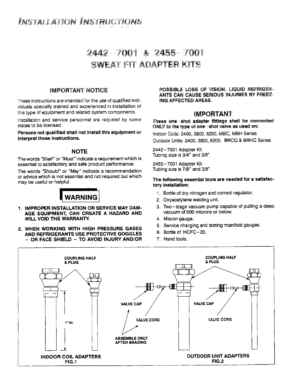
These one shot adapter fittings shall be connected
ONLY to the type o| one, shot valve as used on:
Indoor Coils: 2400, 3800, 6200, MBC, MBH Series
Outdoor Units: 2400, 3800, 6200, BRCQ & BRHQ Series
2442-7001 Adapter Kit
Tubing size is 3/4" and 3/8".
2455- 7001 Adapter K_
Tubing size is 7/8" and 3/8".
The following essential tools are needed for a satisfac-
tory installation:
1. Bottle of dry nitrogen and correct regulator.
2. Oxyacetylene welding unit.
3. Two-stage vacuum pump capable of pulling adeep
vacuum of 500 microns or below.
4. Micron gauge.
5. Service charging and testing manifold gauges.
6. Bottleof HCFC-22.
7. Hand tools.
COUPLING HALF
& PLUG COUPLING HALF
& PLUG
OUTDOOR UNIT ADAPTERS
FIG.2
u
(
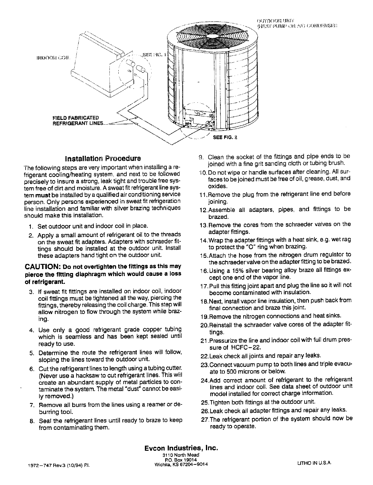
FIELD FABRICATED
J
"_.. J SEE FIG, 2
Unstallation Procedure
The following steps are very important when installings re-
frigerant cooling/heating system, and next to be followed
precisely to insure a strong, leak tight and trouble free sys-
tem free of dirt and moisture. A sweat fit refrigerantline sys-
tern must be installed by a qualified airconditioningservice
person. Only persons experienced in sweat fit refrigeration
line installation and familiar with silver brazing techniques
should make this installation.
1. Set outdoor unit and indoor coil in place.
2. Apply a small amount of refrigerant oil to the threads
on the sweat fit adapters. Adapters with schraeder fit-
tings should be installed at the outdoor unit. Install
these adapters hand tight on the outdoor unit.
CAUTION: Do not overtighten the fittings as this may
pierce the fitting diaphragm which would cause a loss
of refrigerant.
3. If sweat fit fittings are installed on indoor coil, indoor
coil fittings must be tightened allthe way, piercing the
fittings, thereby releasing the coil charge. This step will
allow nitrogen to flow through the system while braz-
ing.
4. Use only a good refrigerant grade copper tubing
which is seamless and has been kept sealed until
ready to use.
5. Determine the route the refrigerant lines will follow,
sloping the lines toward the outdoor unit,
6. Cut the refrigerant lines to length using a tubing cutter.
(Never use a hacksaw to cut refrigerant lines. This will
create an abundant supply of metal particles to con-
taminate the system, The metal "dust" cannot be easi-
ly removed.)
7. Remove all burrs from the lines using a reamer or de-
burring tool.
8. Seal the refrigerant lines until ready to braze to keep
from contaminating them.
9. Clean the socket of the fittings and pipe ends to be
joined with a fine grit sanding cloth or tubing brush,
•1O,Do not wipe or handle surfaces after cleaning. All sur-
faces to be joined must be free of oil, grease, dust, and
oxides.
11,Remove the plug from the refrigerant line end before
joining,
12,Assemble all adapters, pipes, and fittings to be
brazed.
13,Remove the cores from the schraeder valves on the
adapter fittings.
14,Wrap the adapter fittings with a heat sink, e,g. wet rag
to protect the "0" ring when brazing.
15.Attach the hose from the nitrogen drum regulator to
the schraeder valve on the adapter fitting to be brazed.
16.Using a 15% silver bearing alloy braze all fittings ex-
cept one end of the vapor line.
17. Pull this fitting joint apart and plug the line so it will not
become contaminated with insulation.
18. Next, installvapor line insulation, then push back from
final connection and braze this joint.
19.Remove the nitrogen connections and heat sinks.
20.Reinstall the schraeder valve cores of the adapter fit-
tings.
21.Pressurize the line and indoor coil with full drum pres-
sure of HCFC-22,
22.Leak check all joints and repair any leaks.
23.Connect vacuum pump to both lines and triple evacu-
ate to 500 microns or below.
24.Add correct amount of refrigerant to the refrigerant
lines and indoor coil. See data sheet of outdoor unit
model installed for correct charge information.
25.Tighten both fittings at the outdoor unit.
26. Leak check all adapter fittings and repair any leaks.
27.The refrigerant portion of the system should now be
ready to operate.
1972 --747 Rev.3 (10/94) RI.
Evcon Industries, Inc.
3! 10 North Mead
RO, Box 19014
Wichita, KS 67204-9014 LITHO iN U.S.A,
