User Manual
Home Network User Manual
1
Table of Contents
Introduction ....................................................................................................................................................... 3
Part name .................................................................................................................................................. 3
Display composition ............................................................................................................................ 4
1 Screen Saver ........................................................................................................................................... 5
1.1. Information provided from the screen saver .......................................................... 5
2 Home Display ........................................................................................................................................ 6
3 Notice ........................................................................................................................................................ 7
4 Control ...................................................................................................................................................... 8
4.1. FCU Control ............................................................................................................................. 8
5 Application ............................................................................................................................................ 10
5.1. Intercom .................................................................................................................................. 11
5.2. Security .................................................................................................................................... 18
5.3. Home History ....................................................................................................................... 20
5.4. Complex Service ................................................................................................................. 24
5.5. ETC ............................................................................................................................................. 26
6 Scene/Scenario control ................................................................................................................... 31
7 Appendix ................................................................................................................................................ 38
7.1. Using the Owner mobile app ....................................................................................... 38
7.2. Using the Guest mobile app ........................................................................................ 42
7.3. Etc............................................................................................................................................... 45
7.4. Name Search(LOBBY PHONE)....................................................................................... 46
8 Specification ......................................................................................................................................... 38
2
Introduction
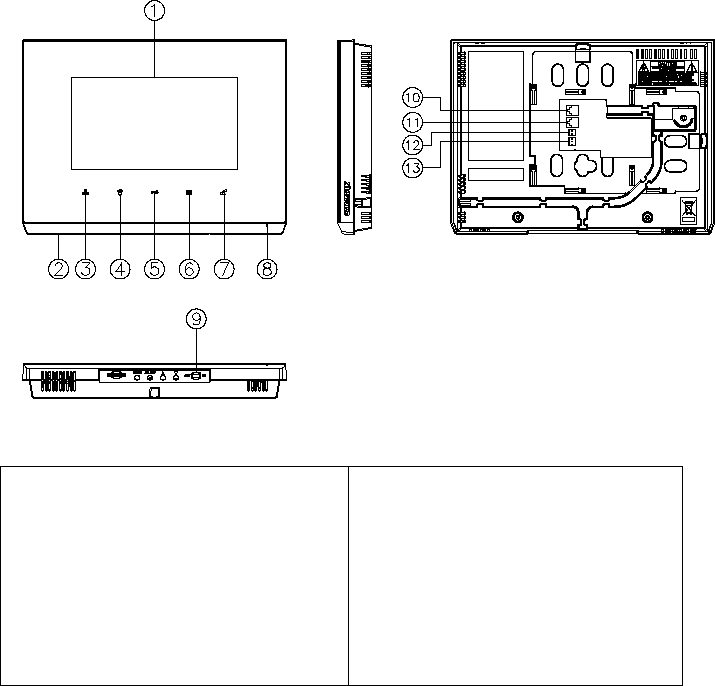
Part name
① LCD
② Speaker
③ Monitoring individual entrance
④ Call guard station
⑤ Door release button
⑥ Call button
⑦ Home Button
⑧ Microphone
⑨ Power Switch
⑩ PoE + LAN
⑪ Camera connector
⑫ EM
⑬ RS-485
3
Display composition
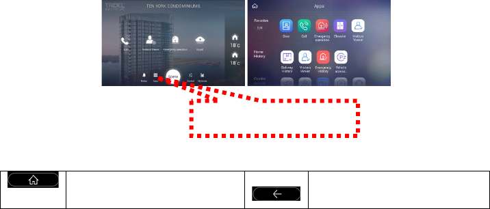
Buttons at the Bottom
Go to Home Back
Press the button
4
1 Screen Saver
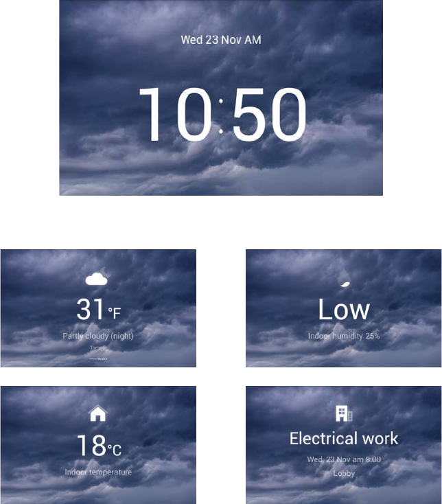
We will provide information on the screen sequentially
Press the screen saver to go to the home screen.
1.1. Information provided from the screen saver
[Today's weather information] [Indoor humidity]
[Indoor temperature] [Notice]
※ It is not provided when there is no information.
※ Weather information should be connected to the external Internet to the server.
5
2 Home Display
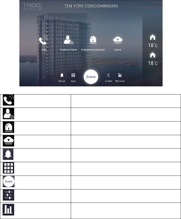
Call Unit-to-unit call
Visitors Viewer Check recorded images of visitors
Emergency operation Panic alert
Guard Calling the guard station
Notice Notice
Apps The list of all installed apps
Scene Scene/Scenario control
Control Device control
My home
Display list of value information of external
environment and our house
6
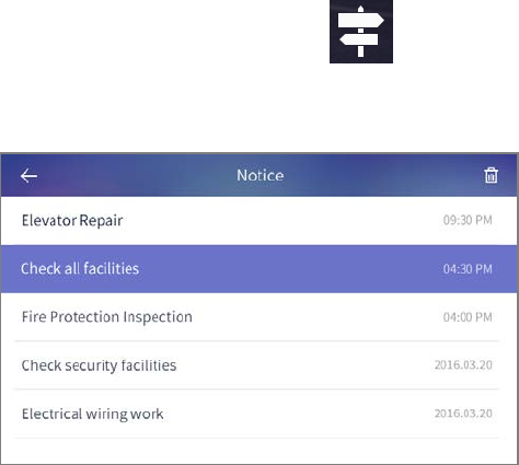
3 Notice
You can check the notices
[Notices]
7
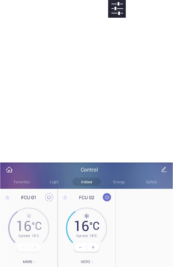
4 Control
4.1. FCU Control
FCU Control
1) Go to the [Indoor] tab.
2) If cold/heating is in operation, the activated image is displayed, and if it
do not work, the disabled image is displayed.
3) You can turn on / off all cooling / heating machines by pressing the power
button of "whole air conditioning / heating".
4) You can enable or disable all cold / heater exit mode by pushing "go out"
button of "whole air conditioning / heating".
5) You can turn on / off the cooling / heating by pressing the power (1)
button of the controlling cold / heater.
6) You can set temperature at one degree difference by pressing the
button(②) .
7) The current temperature is displayed.
[FCU Control]
FCU Away mode
1) Go to the [Indoor] tab
2) Press the ‘More’ button
8
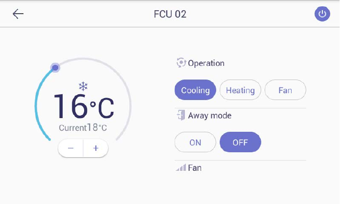
3) Press the "ON" button in the go-out mode to set the go-out mode. Both
the cold / heater will be turned off.
4) Pressing the "OFF" button in the go-out mode releases the go-out mode.
The cold / heating machine will return to the status before going out.
(When you turn on / off the power from away mode setting, you will be
automatically unlocked.)
Change the FCU mode
1) Press the "cooling" button to set the mode for cooling.
2) Press the "Heating" button, the mode is set for heating.
9

5 Application
10
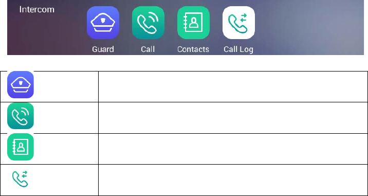
5.1. Intercom
Guard Calling the security guard station
Call call to security guard, call between household
Contacts Contacts
Call Log Call log
11
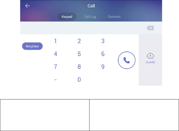
[Call Screen]
① Keypad
② Call Log
③ Contacts
④ Neighbor
⑤ Call
⑥ Entered a phone number
⑦ Delete
⑧ Calling a guard station
①
② ③
④
⑤
⑥ ⑦
⑧
12
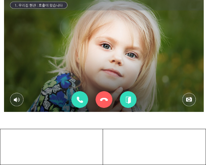
[The screen of calling connection and calling screen]
① Active Call and Call Waiting
② Display of calling connection
③ Volume
④ Call Start
⑤ Call refusal, Cancel
⑥ Door Open
⑦ Save of Visitor image
※ ‘Call display’ can be displayed differently by each type of call from guard station
and entrance
※ Some equipment does not provide CID function.
※ Visitors image can be saved in the storage space.
Images can be stored by 128 cuts. (188MByte standards)
※ The file is same space for visitors image and CCTV Image.
※ Internet telephone cannot be used
①
②
③ ④ ⑤ ⑥ ⑦
13

5.1.1. Common entrance
Open the door for common entrance
1) During the called of individual and common entrance please press
(Door Open) the button.
Recording visitor’s image from common entrance
1) Press ‘Capture an image’ button while paging or calling.
2) If successfully recorded, the visitor's photos which are confirmed visitors
on the home screen will be displayed.
Pick up the phone from Common Entrance
1) The visitor will be displayed on the screen with bell sounds
2) If pick up the phone please press button or please reject button.
3) If hang up the phone please press the button.
14

5.1.2. Guard station
Calling a guard station
Calling a guard station
1) To call a guard station, touch ‘Guard station’ icon or touch ‘Guard station’
button in dialing mode
2) To hang up a call, touch ‘End call’ button.
Receiving a call from a guard station
1) When the call is received from a guard station, the touch panel rings and
displays a guard station icon on the screen.
2) To receive a call, touch (Call) button. To reject a call, touch ‘Cancel’
button.
3) To hang up a call, touch ‘End call’ button.
※ Security office and management office cannot see the user’s image.
※ The guard video call is only available for products with video call cameras
※ If you use the call transfer function during the guard station call, the guard
station call is automatically terminated
※ Setting of security office -> Connect to COMMAX and control -> setting to
number -> Security and management office can be settled.
15
5.1.3. Make a Phone
Calling between household
Calling a guard station
Making a household unit-to-unit call
1) Touch ’ Neighbor’ button
2) Enter the number of a household unit (including a building number if
more than one building exists) and touch Call) button.
(When you enter the unit number, ‘*’ should be inserted between the
building number and the unit number. Ex. Building# 3, Unit# 102 →
3*102)
3) Connecting tone sound is ringing and an indication of connecting is
displayed.
4) To hang up a call, touch ‘End call’ button
Receiving a household unit-to-unit call
1) When you received call from another household unit, the touch pad rings
and indicates a call type.
2) To receive a call, touch (Call) button. To reject a call, touch ‘Cancel’
button.
3) To hang up a call, touch ‘End call’ button.
16

Making a video call for a household unit-to-unit (Option)
1) Same as making a unit-o-to-unit- call.
2) As a connection is made, touch button to send your live video.
※ Video call is enabled only if the household unit device has a built-in camera.
※ The call recipient can see your video only if you allow it by touching the ‘Video
call’ button.
※ There is only one communication channel available. It means the touch panel can
receive a page from another location while talking to another resident however,
once you receive the second call the previous connection will automatically be
disconnected.
Call switching function
1) If someone calls you during a calling, it will be displayed on the screen.
2) Touch (Switch call) button to answer the call. The previous call is
disconnected as you switch the call
※ Some devices do not provide CID functionality (Caller ID).
※ Call transfer is not supported on some calls
17
5.2. Security
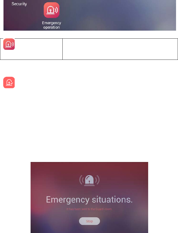
Emergency
operation
Emergency in emergency situation
6.2.1. Emergency
Emergency occurrence
Emergency sensing
An emergency occurs by the user or occurs automatically by the sensor
Touch ‘Emergency’ button to send a notice of an emergency to Guard station. The
emergency notice is processed in three steps such as ‘On’, ‘Off’, and ‘Reset’
Emergency on
1) Emergency can be generated by pressing the emergency icon or by
pressing the emergency button on the front of the product. Or
automatically by the sensor
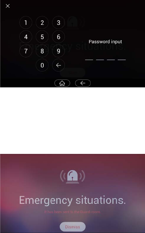
2) Emergency type is displayed at the top of the screen with a siren sound
[Emergency]
18
Emergency stop
1) Touch ‘Stop’ button located at the bottom of Emergency screen.
2) Put the password (default password is ‘1234) and then press enter’.
[Password input]
Emergency reset
1) If password accepted, the ‘Off’ button is changed to ‘Reset’.
2) Touch ‘Reset’ button.
3) The emergency is off and reset to normal.
[Emergency Reset]
19
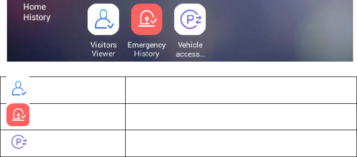
5.3. Home History
Visitors Viewer Viewing recorded images of visitors
Emergency History Emergency History
Vehicle access History Vehicle access History
20
5.3.1. Visitors Viewer
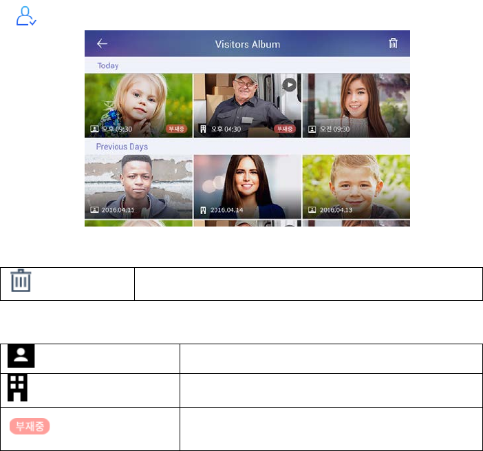
Viewing recorded images of visitors from common entrance.
[Viewing recorded images of visitors]
Delete Delete selected images
You can see where the picture was taken with the icon.
My house Picture taken at my house
Common entrance Images taken from an common entrance
Out In case of go-out
(Go out mode settings)
Viewing recorded images
In viewing a visitor mode, all recorded images from a common entrance can be
checked including time and date information. You can also check visitors if you set
out.
Deleting recorded images
1) Touch ‘Delete’ button.
2) Select images or all the images by checking ‘Select all’ box.
3) Touch once more to uncheck the images or ‘Select all’ box.
4) Touch ‘Delete’ button to delete selected images.
21
5.3.2. Emergency History
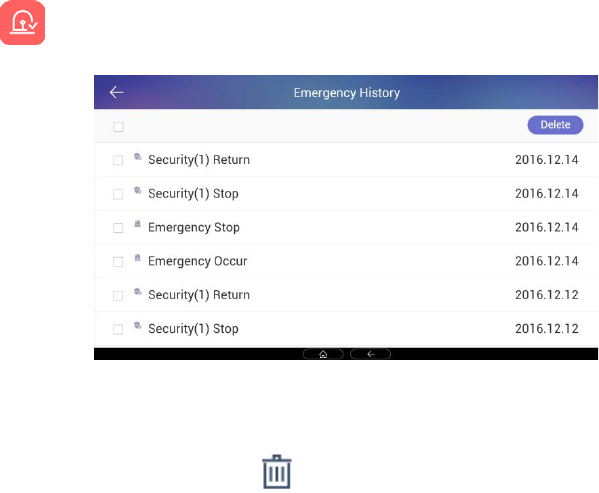
Emergency History
[Emergency History
Display]
Deleting emergency History
1) Touch ‘Delete’ button to delete the emergency history.
22
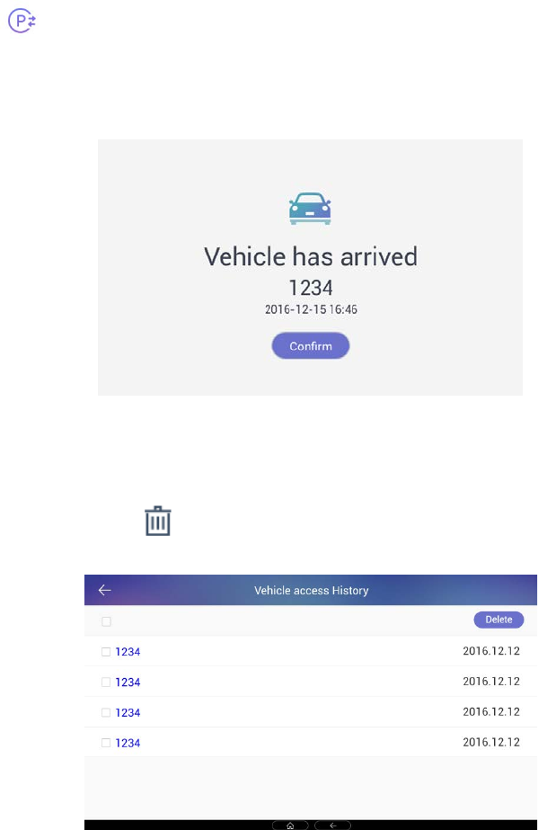
5.3.3. Vehicle access History
Vehicle access alert
Vehicle access History
When the vehicle arrives, an image of the arrival notice of the vehicle is displayed
on the screen together with the notification sound.
When you click 'confirm' button, the arrival image of the vehicle disappears.
[Vehicle access alert]
Vehicle access History
1) You can check Vehicle access History
2) Press the 'Delete' button to delete the Vehicle access history.
[Vehicle access History]
23
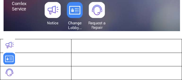
5.4. Complex Service
Notice You can check the notices
Change Lobby Password Change Lobby Password
Request a Repair Request a Repair
24
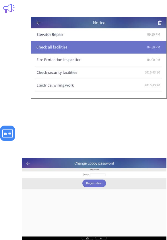
5.4.1. Notice
You can check the notices
[Notices]
5.4.2. Change Lobby Password
1) Enter your lobby password and touch ‘Registration’ button.
2) Changing lobby password is completed
[Change Lobby Password
25
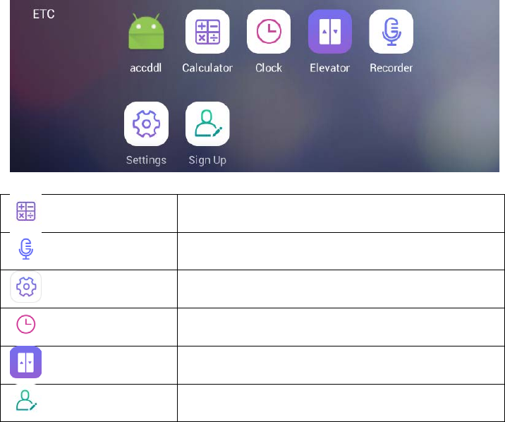
5.5. ETC
Calculator Calculator
Recorder Sound recorder
Settings Settings
Clock Alarm and clock
Elevator Call elevator is available.
Sign Up User registration
26
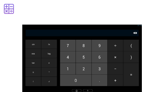
5.5.1. Calculator
Calculator
The calculator funinctions are provided
[Calculator]
27
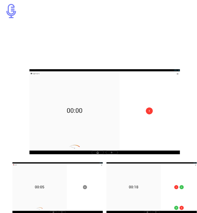
5.5.2. Sound recorder
Voice recorder
Recording a voice message
1) Touch ‘Record (①)’ button.
2) Touch ‘Stop (②)’ button to stop recording and select ‘Finish recording’ to
complete recording or ‘Delete’ to delete the message.
3) Touch ‘Play (③)’ button to listen to the recorded message
[Voice recorder]
①
②
③
28
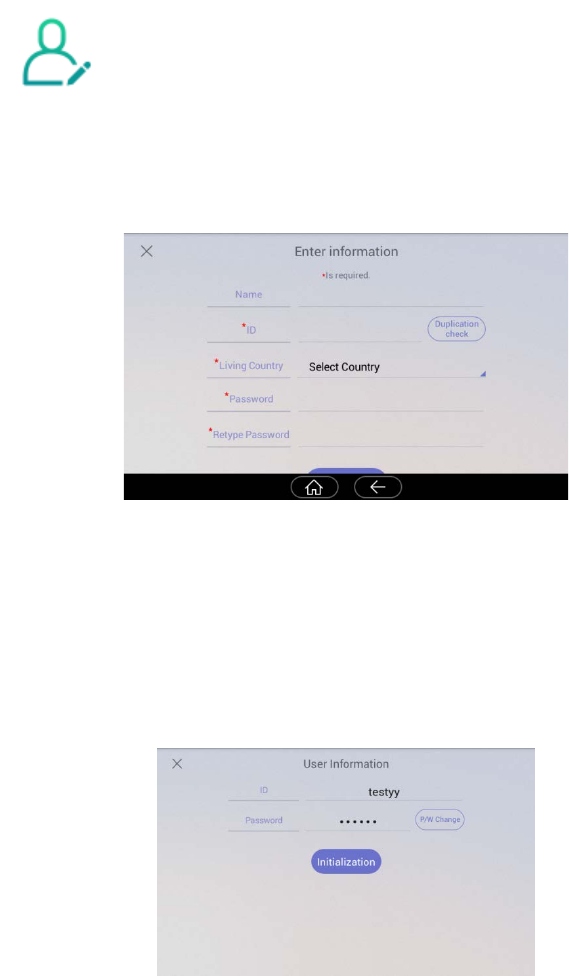
5.5.3. Sign Up
User registration/ Edit / Reset
1) Enter your ID and touch ‘ID check’ button to check for validity
2) Select your country
3) Enter your password and touch ‘Confirm’ button.
[Sign Up]
Renew, initialize
1) If membership has been registered, items of member information will be
displayed. To change the password, you can change the password by pressing
the "P/W change" button.
2) If membership has been registered, pressing the "Initialization" button deletes
the registered member information.
29
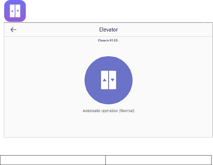
5.5.4. Elevator
Call elevator is available.
[ELEVATOR CALLER]
① Display time limit ② Elevator call
Elevator call
1) Call elevator to click image ② (elevator)
2) After the display time limit (2 minutes), the program is ended
※ The function of elevator interlocking can only be used in the field where elevator
status check and call service is available
①
②
30
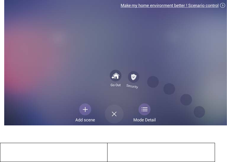
6 Scene/Scenario control
[Scene/Scenario control]
① Go to home screen
② Add scene
③ View the details of the scene
④ Scenario control
①
②
③
④
31
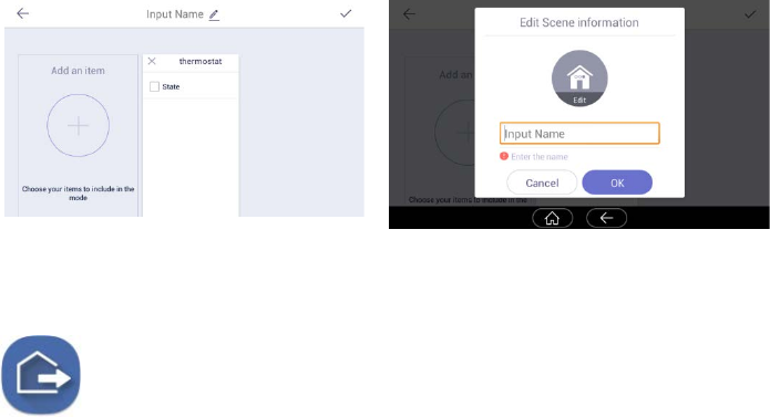
6.1.1. Add scene
1) Press the 'Add Scene' button on the 'Add Scene Main Screen'.
2) Press the 'Create scene directly on selected device', the device selection
dialog window will be displayed.
3) Select the setting device and press the 'OK' button in the upper right.
4) Setting Select and set the properties of the device.
5) Press the Enter Names button at the top of the screen center to set the
name and icon.
[set properties of the device]
[set the name and icon.]
6.1.2. Go Out
Go out /on
The status display of going out setting
When you go out, you can set up these functions security sensor, visitor recording,
light off, close gas valve, indirect call etc.
Go out mode setting
1) Press the icon, away mode will be started.
2) The Go out(away) mode will be executed automatically after the specified
Go out delay time.
3) If you want to cancel go-out mode, press ‘CANCEL’ button.
32
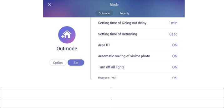
[Go Out mode set-up]
1.Delayed time for go-out 3.Start go-out(away) mode
2.Action item when going out
※ If security mode is on, away mode cannot be started.
※ Return home sensor delay setting is set by setting -> user option -> delayed
from adjusted go out time.
Set Go Out mode
1) Set items to be executed when go out mode
2) Press the ‘Option’ button on the setting screen of go out mode, the
setting screen of go out mode is displayed.
3) Check the use security sensor and execution item to use.
4) Press ‘confirm’ button to save.
Restore Go Out mode
1) Press “Go Out mode“ button
2) When it appears on the password input screen, enter the password and
click the 'confirm' button.
3) If the passwords match, go out mode will be canceled.
②
③
①
33
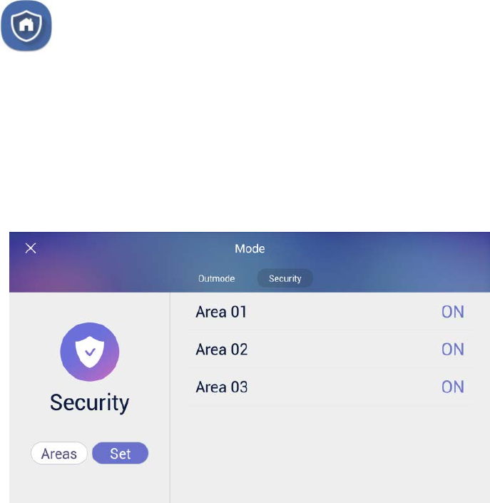
6.1.3. Burglar sensor settings
burglar sensor settings on
burglar sensor settings off
※ This function will be activated when the security devices have been installed.
※ You can set the using security sensors in ‘Setting>Connections COMMAX>
Sensors’.
Burglar sensor settings
1) Check the security sensor to be set by pressing the 'Areas (②)' button.
2) After settings, press ①(set) and the burglar sensor in adjusted area will be
started.
[Burglar sensor settings]
※ The number of burglar sensor settings images will be displayed as many as the
number of adjusted sensors.
Restore the burglar sensor
1) Press the 'Burglar sensor settings' button
2) Input the password and press the 'confirms'
3) If password is correct, the security mode will be restored
① ②
34
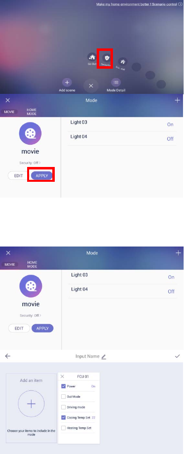
6.1.4. Scene control
1) Press the scene to be executed
in the list.
2) The set device is controlled all
at once.
3)
Press the "Mode Detail"
button on the main screen of
scene / scenario control.
4)
Press the "Apply" button to
control the set device at once.
6.1.5. Scene Edit
1) Press the
"Security: on>"
button to enable or disable
crime prevention when
executing that scene.
2) Press the "Edit" button to edit
the scene.
3)
You can add and edit device
type, device properties, scene
name and icon in the edit
screen.
35
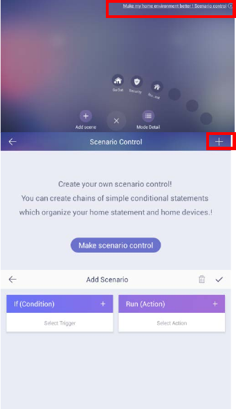
6.1.6. Set scenario control (Mode)
You can operate the desired function according to the conditions set by the
scenario control
Example) Lighting in the living room when going out is ON
※ Depending on the status of the server, the control time may take up to 1
minute, it may take up to 5 minutes.
6.1.7. Add scenario control
1) Press the "Scenario control" button
in the upper right.
2)
Press the "Create Scenario Control"
button or the "+" button at the top.
3)
Press the "+" button at the upper
right of "Condition".
36
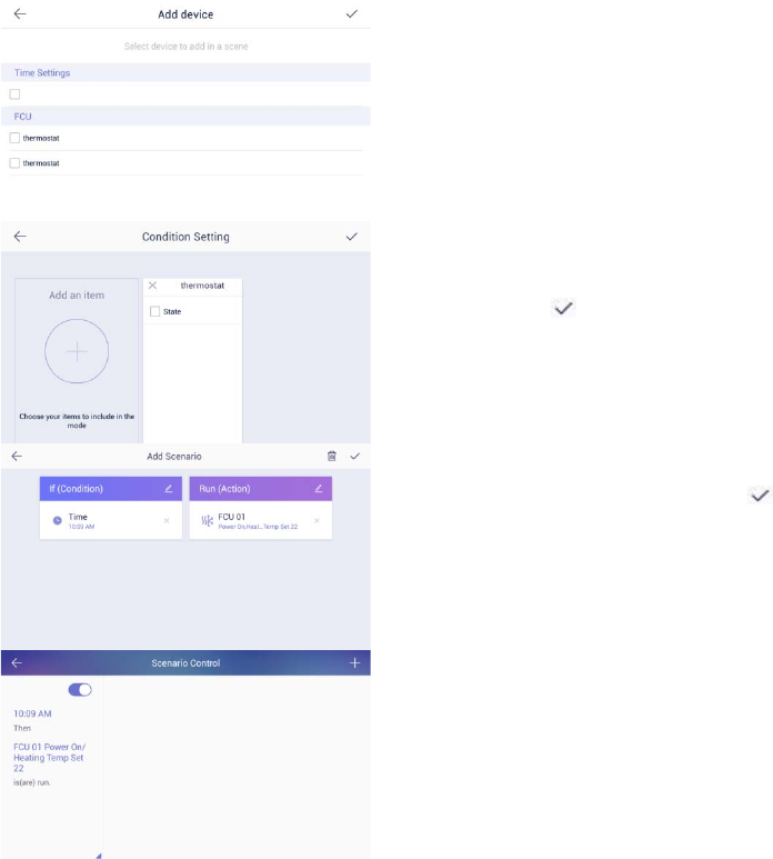
4) Select the setting device.
5)
Select the item of the selected
device.
6) Press the ‘ ’ button at the top
right to save.
7) Set the "Action" setting as 4) ~ 6) in
the same way as "Condition".
8)
When setting of "condition" and
"Action" is completed, press the ‘ ’
button in the upper right to save.
9) The generate
d scenario control is
displayed.
37
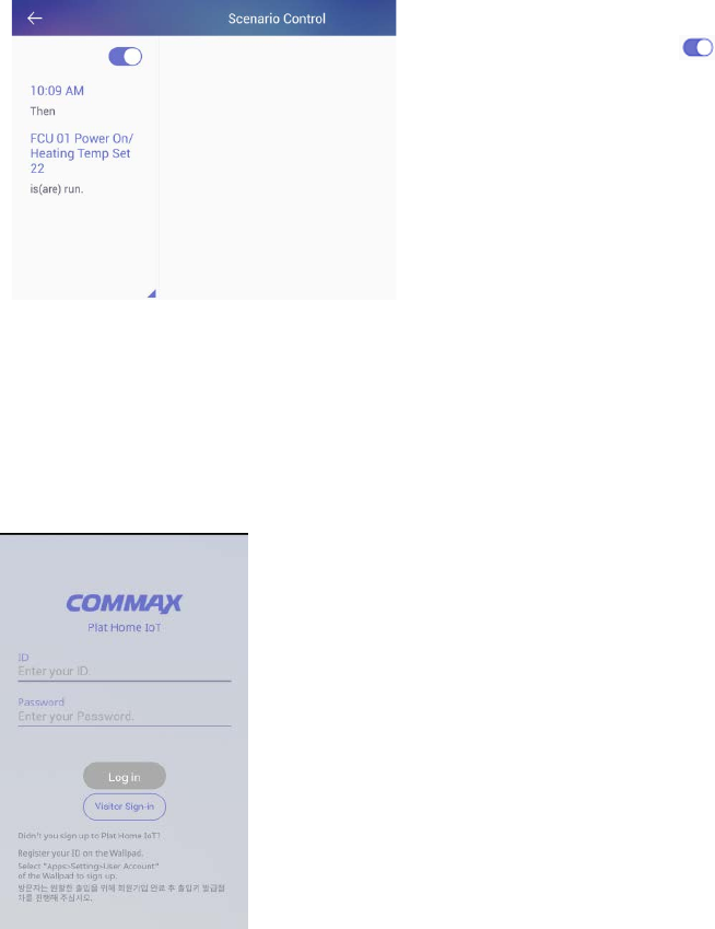
6.1.8. Set whether to use reservation control
1) Go to the reservation control screen.
2) Use the toggle buttons (‘ ’) from
the list to enable or disable the
features you want to use
7 Appendix
7.1. Using the Owner mobile app
Login
1) Enter the ID and password that you registered
to in the Wallpad
2) Press the "Login" button.
3) Enter your nickname and Press the 'OK' button.
38
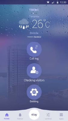
4) In the home screen, you can select "Call Log",
"Checking visitors", and "Setting".
39
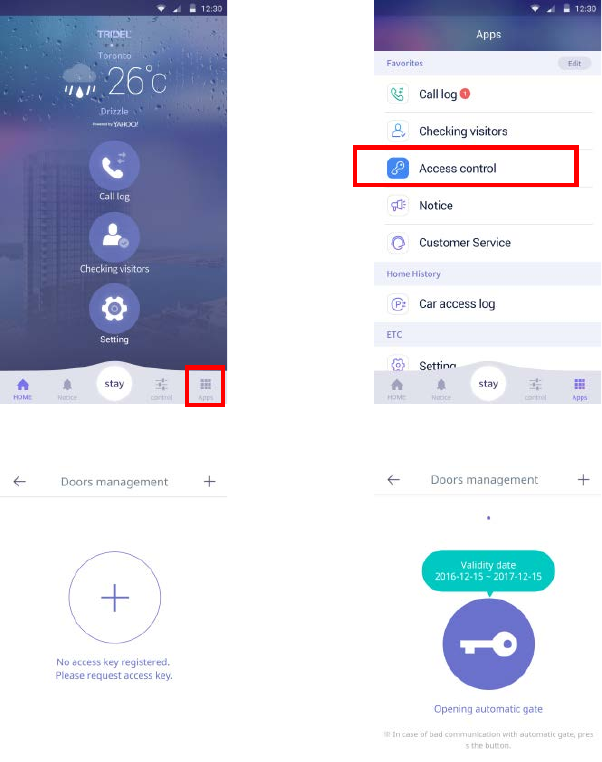
Issuing Access Keys
1)
Press the 'Apps' button on the
home screen.
2) Press the ‘Access Control’ button.
3) Press the ‘Doors management’ button.
4) Press the "+" button
and the
access key will be issued.
5) “①”If there is more than one key that
has been issued
, you can move it by
checking the left / right page.
6) “②”The expiration date of the access
key is displayed.
7) “③”If
not recognized automatically,
press the "Open d
oor" button to open
the door.
①
②
③
40
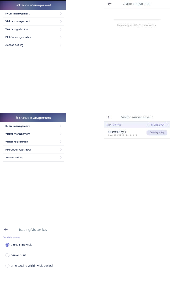
Guest Visit Key Issued
1) Press the ‘Visitor registration’
button.
2) Press the ‘Request’ button.
3) The issued authentication key will
be notified by phone or SMS to the
guest within 3 minutes.
4) When the validity time has elapsed,
the authentication key is reissued.
5) Press the ‘Visitor management’
button.
6) After the guest registers, if you
enter the authentication key, Guest
is displayed in ‘Visitor
management’.
7) Press the ‘Issuing a key’ button
8) You can set the visitor's visit time.
- One-time visit
- Period visit
- Time setting within a period
41

7.2. Using the Guest mobile app
Login
1) Press the ‘Visitor Sign-in’ button.
2) Enter ‘Visitor Name’, ‘ID’, ‘Password’, ‘Retype
password’.
3) Press the ‘Next’ button.
4) Press the ‘Login’ button when the registration is
completed.
42
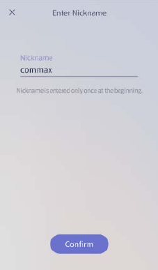
5)
Enter the nickname to use and Press the
‘Confirm’ button.
43

Request a visit key
1) Press the "+" button to request a visit key.
2) Enter the authentication
key received from the
owner.
3)
When the owner confirms and releases the
access key, the access key is displayed.
4) “①”The expiration date of the
access key is
displayed.
5) “②”
If not recognized automatically, press the
"Open door" button to open the door.
①
②
44

7.3. Etc
Door Open
1) Touch the keypad on the door lock (DDL).
2) If the "Auto Setup" is set, the door automatically
opens.
3) If "Auto Access" has not been set, you can press the
"Door open" button on the Mobile Appliance to enter
or exit.
Door lock(DDL) setting
Setting Manual Lock
1) Touch the keypad of the door lock (DDL).
2) Enter the password for the door lock. (Ex)) password:
2580)
3) Enter #+#+7.
(Ex: 2580##7)
Setting Auto Lock
1) Touch the keypad of the door lock (DDL).
2) Enter the password for the door lock. (Ex)) password:
2580)
3) Enter #+#+4.
(Ex: 2580##4)
※ If you set the door lock (DDL) manually, you must touch the keypad to
lock the door when closing the door lock
45
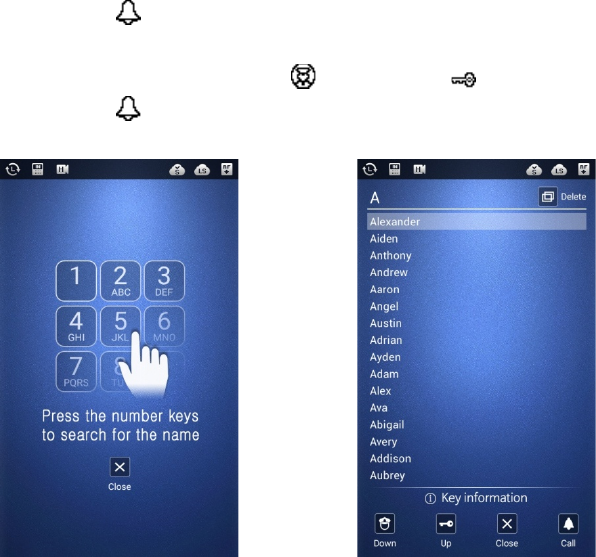
7.4. Name Search(LOBBY PHONE)
①Press the (Call) button.
②Input the name by using keypad.
③Select the user name by using (Guard)”Down”, (Key)”Up” button.
④Press the (Call) button, than Call the house.
[Keypad input display] [ Name input display]
※ Name Search function is available only English version. (Key Timeout: is about
25s)
※ To press the alphabet on same keypad, input the key in 2 seconds.
※ (In case 2 seconds over, color of alphabet will change.)
46

8. Specification
Model
Spec CIP-700SW
Transmission Lobby : LAN, RS-485 : 3 wires
Voltage PoE 36V ~ 54V
Power Consumption Standby :5W , Max :12W
Telecommunication VoIP
Call Tone Lobby : Wave Melody
General : Wave Melody
Wireless ZigBee, HA 1.2
Call Distance UTP Cat5.e / 100m
Temperature 0℃ ∼ +40℃
47
FCC Statement
15.19:
This device complies with part 15 of the FCC rules. Operation is subject to the following two
conditions: (1) This device may not cause harmful interference, and (2) This device must accept any
interference received, including interference that may cause undesired operation.
15.21:
Note: The grantee is not responsible for any changes or modifications not expressly approved by
the party responsible for compliance. Such modifications could void the user’s authority to operate
the equipment.
15.105(b):
Note: This equipment has been tested and found to comply with the limits for a Class B digital device,
pursuant to part 15 of the FCC Rules. These limits are designed to provide reasonable protection
against harmful interference in a residential installation. This equipment generates uses and can
radiate radio frequency energy and, if not installed and used in accordance with the instructions,
may cause harmful interference to radio communications. However, there is no guarantee that
interference will not occur in a particular installation. If this equipment does cause harmful interference
to radio or television reception, which can be determined by turning the equipment off and on,
the user is encouraged to try to correct the interference by one or more of the following measures:
- Reorient or relocate the receiving antenna.
- Increase the separation between the equipment and receiver.
- Connect the equipment into an outlet on a circuit different from that to which the receiver is connected.
- Consult the dealer or an experienced radio/TV technician for help.
The manufacturer, importer, and distributor shall not be liable for damages including accidental and
personal injury due to the improper use or operation of this product. The information in this
user manual was written based on current product specifications. The manufacturer, iriver Limited,
is adding new complementary features and will continue to apply new technologies in the future.
Product specifications may be changed without prior notice.
iriver is not responsible for data loss due to product use.
Disclaimers
48
The transmitter must not be co-located or operated in conjunction with any other antenna or
transmitter. This equipment complies with the FCC RF radiation exposure limits set forth for an
uncontrolled environment. This equipment should be installed and operated with a minimum
distance of 20cm between the radiator and any part of your body
RF Exposure statement