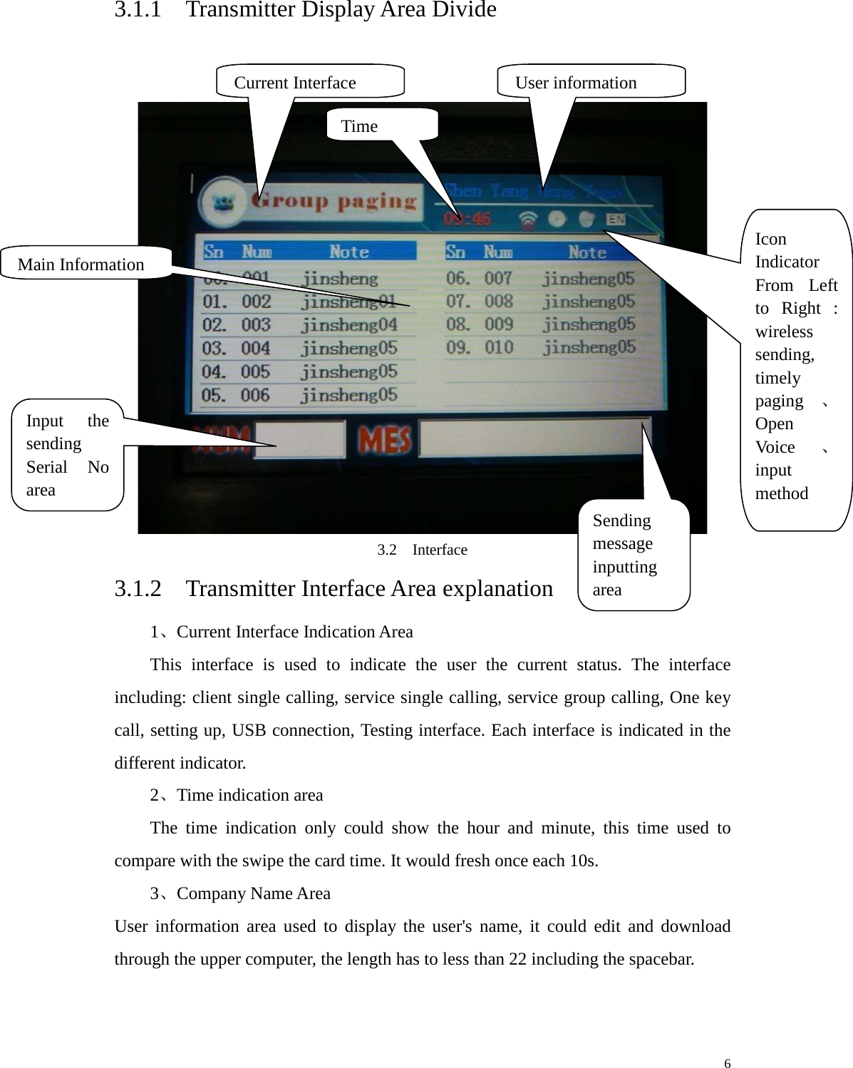
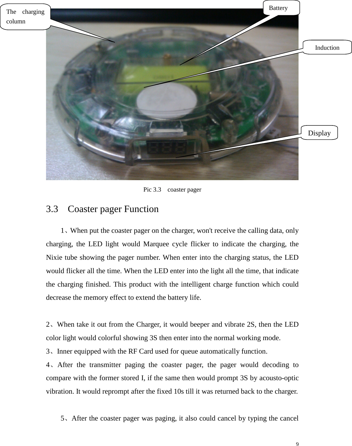
CONSTANT ELECTRONICS T21 Paging Transmitter User Manual qif

SHENZHEN CONSTANT ELECTRONICS CO., LTD. Paging Transmitter qif

User Manual

       T21 User Manual                         1
                       Content 1  Product Outline ................................................................................................ 1 2  System Parameter............................................................................................. 1 2.1  Transmitter Parameter ........................................................................... 1 3  Product appearance .......................................................................................... 4 3.1  Transmitter Appearance ........................................................................ 4 3.1.1    Transmitter Display Area Divide ............................................... 6 3.1.2  Transmitter Interface Area explanation ...................................... 6 3.2  Transmitter Function ............................................................................. 7 3.2.1    Transmitter Special function Introduction ................................. 7 3.3................................................................................................................... 8 3.3    Coaster pager Function ......................................................................... 9 3.4    Coaster Pager ID arrangement ............................................................ 11 4  Operation Guide ............................................................................................. 12 4.1    Transmitter operation Guide ............................................................... 12 4.1.1  Paging Customer Interface ....................................................... 12 4.1.2    Staff Single Paging interface .................................................... 13 4.1.3    Staff Group Paging Interface ................................................... 15 4.1.4   interface set up ....................................................................... 16 4.1.5    Single key paging interface ...................................................... 20 4.2    Coaster Pager Operation Instruction ................................................... 20 4.2.1  Entering Information ................................................................ 20 4.2.2  Queue ....................................................................................... 21 4.2.3  charge ....................................................................................... 21 5  Application ..................................................................................................... 21 5.1  Wait Meal ............................................................................................ 21 5.1.1  Prepare work ............................................................................ 21 5.1.2  Queue ....................................................................................... 22 5.1.3 Customer wait ............................................................................. 22 5.1.4    Delete the wait meal information ............................................. 23     2
    5.2  Staff Paging ......................................................................................... 23 5.3    other special function .......................................................................... 24 6  Breakdown & Solution .................................................................................. 24 7. FCC Important Note ........................................................................................ 25 FCC Part 15.19 Warning Statement ............................................................. 25 FCC Part 15.21 Warning Statement ............................................................. 26 FCC Part 15.105(b) Warning Statement ...................................................... 26 RF EXPOSURE ........................................................................................... 26     3
  1  Product Outline Guest Paging System including: Transmitter+Coaster Pagers. When using, dispatch the Coaster Pager which with the Exclusive Code to the customers. The customer could find a seat to relax or go outside stroll about. When the Dishes are ready or have the empty seat, the staff would input the coaster pager No to notice the customer return. The Customer would notice this by Coaster pager ring, light or vibrate prompt.   Extended Function: The system except work with the Coaster pager but compatible with the pager which with LCD display which wore by the manager or staff to fulfill the inner calling communication function.   Special Function:   We added the swipe the card function to fulfill the convenient queue function. In the coaster pager we could install the RFC, and Reader Module in the Transmitter. When Customer need queue Function, just swipe the Coaster Pager in the Transmitter, then it would be in queue state. When Calling the customer, just find that number in the queue and press the send key is ok. Which decrease the Waiters work greatly to improve the efficiency.   2  System Parameter 2.1  Transmitter Parameter Type Parameter Overall Size 220mm × 130mm ×45mm Display Resolution 400×240 Keypad T9(letter and numeric)     1
  Power Supply 12V/ 3A Interface type USB、RS485(Ethernet available) Frequency Customization available Paging number in cache 40 Queuing display 3 digit LED nixie tube   Card type RF Card Transmitting Power 0-2W adjustable Antenna External BNC Socket System Capacity Coaster Pager —999 Waiter Numbers——999 Default single key paging ——10 Timely paging ——10 Table 2.1  Transmitter Parameter    2.2  Coaster Pager Parameter      Overall size 112mm(Diameter) × 17mm(Thickness) Frequency Customization available Sensitivity -110DBm Decoding POCSAG ,Support 7 group ID code     2
  Coaster pager number 3 digit,001-999 Alert mode Vibration and sound,with LED flashes Out of Range Alert Alarm when out of the transmitter range Lower Power Prompt Buzzer sounds “didi” Water resistant design Surface water resistant Power supply 2.4V/600mAH Standby Current 500uA Temperature -0℃—+65℃ Table 2.2  Coaster Pager Parameter     2.3  Charger Parameter    Overall size 112mm(diameter) × 17mm(thickness) Input DC-12V/1.5A Output DC-5V Rechargeable Coaster pager capability 15 Efficiency 65% Standby Current 500uA Temperature -0℃—+65℃     3
   Table 2.3  Charger Parameter    3  Product appearance 3.1  Transmitter Appearance The Transmitter Panel including the display area, key area, swipe card area and   The Buzzer speaker mouth. For function please refer to:  ESC  ——  Return   ENT  ——  Confirm F1    ——  Switch Client/Service Paging interface F2    ——  In Service Paging Interface switch Single Paging/Group Paging   F3    ——  Enter/Exit Single key Paging interface F4    ——  Enter Setup Interface   0~9   ——  T9 *     ——  Delete Key( press shortly to delete one Character, press long time to clear all of the cursor position Characters) #     ——  Switch typewriting(Number inputting, Small Letter, Capital form of the english inputting)           4
   3.1 Transmitter    Transmitter Interface picture 3.2     3.2  Transmitter Port keypad Display area Swipe Card Buzzer speaker mouth Power   485   internet USB antenna     5
  3.1.1  Transmitter Display Area Divide    3.2  Interface 3.1.2  Transmitter Interface Area explanation 1、Current Interface Indication Area This interface is used to indicate the user the current status. The interface including: client single calling, service single calling, service group calling, One key call, setting up, USB connection, Testing interface. Each interface is indicated in the different indicator.   2、Time indication area   The time indication only could show the hour and minute, this time used to compare with the swipe the card time. It would fresh once each 10s.   3、Company Name Area   User information area used to display the user's name, it could edit and download through the upper computer, the length has to less than 22 including the spacebar.    Current Interface User information Time  Icon Indicator From Left to Right : wireless sending, timely paging 、Open Voice 、input method Main Information Input the sending Serial No area Sending message inputting area     6
  3.2  Transmitter Function   1、Single Call   Single call one coaster pager or pager receiver, won't page the other receivers. 2、Class Call Could call in class. One is call the staff pagers, the other is call the staff coaster pager. Once call, the class pagers would ring.   3、Group call It could edit and make a group through the PC software in advance, name the same group pagers in 1 group, then send the message to the transmitter. When operate the group call, the transmitter would send the same message to the group members one by one. 4、One key call   In one key call interface, it could fulfill the one key calling through the number in the keypad, send the fixed message to the fixed pager.   5、Set up Function   Could set up the transmitter message parameter. 16、Program backup and restore function   To prevent there's some problem occurred during the program upgrade, we use the program automatical backup function. When there's program upgrade, it would backup the original program automatically. When there's some problem occurred in the new program, it could restore to the original program manually.   17、Induction Card Swipe Card function   The system with the induction card recognition module which could fulfill the swipe the card to queue function.   3.2.1  Transmitter Special function Introduction    1、Program backup Automatically function For the transmitter with the program backup automatically function, even in the     7
  special situation the upgrade failed, the system won't be broken down, it could return back to the program code before the upgradation following the below step:  In the power cut off status, press the F1 and F2 key simultaneously, then plug the power in, the screen would turn black, then appear the yellow font. When the first line displaying:  Reply_original_program...., it indicates that could restore the original backup program. Then release F1, F2 , it would restore to the former system after the backup finished. At this time it could download the new program in the correct manner again.     Remark:This backup program could be used only after the upgradation of the new program, or the operation won't be valid. 3.3                    8
   Pic 3.3  coaster pager 3.3  Coaster pager Function 1、When put the coaster pager on the charger, won't receive the calling data, only charging, the LED light would Marquee cycle flicker to indicate the charging, the Nixie tube showing the pager number. When enter into the charging status, the LED would flicker all the time. When the LED enter into the light all the time, that indicate the charging finished. This product with the intelligent charge function which could decrease the memory effect to extend the battery life.    2、When take it out from the Charger, it would beeper and vibrate 2S, then the LED color light would colorful showing 3S then enter into the normal working mode.   3、Inner equipped with the RF Card used for queue automatically function. 4、After the transmitter paging the coaster pager, the pager would decoding to compare with the former stored I, if the same then would prompt 3S by acousto-optic vibration. It would reprompt after the fixed 10s till it was returned back to the charger.      5、After the coaster pager was paging, it also could cancel by typing the cancel Battery  Induction  Display The charging column     9
  command in the transmitter. The prompt voice is long Di...Di and vibration, and the LED flashing. It would enter into the standby status after the acousto-optic vibration Ended.       6、 When the queue number prompt function open, it would send the queue number message when sending the heart beat protocol data. When the queue number decreased, it would prompt by showing current queue number and the pager ID, Long Di....Di and vibration, LED light would flash twice. It would enter into the standby status after the acousto-optic vibration prompt.   7、Swing show function. In order to save the power, the coaster pager would enter into the low consumption standby status after 10 s without touch. When the customer want to see the queue number or the pager ID, just by swing silently the Nixie tube would be light automatically to show the prompt message 10s then enter into the low power consumption status.   8、In the side of the pager, there's a 3 digits Nixie tube display. It would show its ID number in the fetch dish mode. In the Queue Mode, it would show the queue number. Such as : n-2, it means there're two persons before are waiting. The Max queue number is 9. Over 9 persons it would show "Full". The NiXie Tube adopts dynamic scroll mode, the Pager ID number and the queue number switch showing each 3S.   10、Support the cross the border prompt,. The pager would warm when the pager doesn't receive the heart beat data after the setup interval, to prompt the customer return within the signal coverage. If the customer won't return back, the warning would ring all the time. The overtime interval could be modified through the PC software.     11、Wireless Distance testing function. When the transmitter enter into the testing status, it would send out one testing command each 10s, the pager would DiDi prompt when receive the message. This function used for testing the distance during installation.   12、Low Power inspecting function. When the single-chip detect the battery is too low, it would prompt the user by the beeper warning from high to low volume,     10
  and flash showing "LLL" .    At this time, the user has to charge immediately.   13、Communicate with the PC software function. The parameter could be set up through the PC software. By the special burning connector download the data into the coaster pager memory.     14、In the transmitter testing mode, all of the coaster pagers receive the testing data. the pager would flash twice for 0.5s in colorful light after got the data. In  the coaster pager it could store as much as 7 addresses. It named ADDR1-ADDR7. But the address numbers in the pager decided by the users situation. 3.4  Coaster Pager ID arrangement 1、Group address ADDR1 as group address. In this status, all of the coaster pagers and staff pagers ring at the same time.   2、Category Address ADDR2 as category address. It including two types: one is call for the staff. The other is call for the customer coaster pagers. 3、Pager ID  ADDR3 as the Single coaster pager calling,when the transmitter choosing the coaster pager Id to page, the transmitter would send the code according to this ADDR3 ID.             11
  4  Operation Guide     4.1  Transmitter operation Guide 4.1.1  Paging Customer Interface Sn is the queue serial No.  ,Num is the customer's Serial No. In the waiting for fetching the dish mode, Pn stand for persons numbers.In the fetching the dish mode, Pn stand for order message, Cn is the status, wheen it is in green, it means the message has been sent out.    Time is the queue record time.  4.1  paging customer interface 1、Page the coaster Pager   In the customer paging interface, the cursor would stay in the inputting code area, there're two methods to input the code:      1:use the key 0-9 type the number,in inputting the system with the index automatically function. Such as: to page the 008 coaster pager, you could input 008, 08, 8 are all ok. And the     12
  system would position the chosen message automatically, and pitch on, at this time you could   Press the SEND key to send. If in the fetching the dish mode, if inputting the SN, it would search according to it, if typing # plus order No. It would search according to the order #. Such as to search the order 1234, just input#1234,if input #125, then it would turn to red which means the wrong typing.   2:use the upper key to move the cursor to the middle message area, the message would be inverse. It could modify the SN through the Up & Dn keys, the corresponding SN would be displayed in the SN area. By Pressing ESC, the cursor would returned back to the SN inputting interface, at the same time the SN area would be cleared.   If the SN inputting wrong, it would display X in the SN area. Remark:in paging the customer interface, could input the edited message in the message edit area, but it won't as the sending content. The sending content has been fixed in the system. 2、Send the cancel command The SN of the coaster pager small icon would turn green after paging finished. If you want to stop this paging, use the cursor choose this message, then click on "Confirm" , then it would bounce up a dialogue box to prompt: whether you confirm to cancel. Press "Confirm" to cancel.   3、Group calling   Put the cursor in the SN area, input "0", then press "SEND" key, at this time the screen would bounce up a dialogue to confirm whether send the Group Calling command. This Group Calling means all of the coaster pagers, click ENT to send out.   The times of clicking ENT, means the sending out times. It would exit till ESC was clicked.    4.1.2  Staff Single Paging interface Staff Calling Interface  picture4.2,Sn(Serial Number),Num(Number),Note(Remark).     13
   picture 4.2  Staff Calling interface In the staff calling interface, the method of inputting SN is the same as paging the customer. The only difference is that the message input in this interface message input box as the sending message. After the number was input, press the "ENT" to enter into the message edition interface, in this interface it would show the fixed message. When the cursor move to the fixed message, it could page turn. The chosen message SN would be shown in the message inputting area, at this time, click the "SEND" key, the SN+ message SN would be sent out. If want to send the message, after chosen the message, click "ENT" , then the chosen message would be shown in the message area, at this time, you could edit the message through the keys. Press the SEND, the message would be sent. If the message exceed the message area capacity, it would show part content. At the same time, could page turn the message through the pg up & pg dn. When pg up to the top,press the pg up, the cursor would turn to the fixed message area, and the message display area message would be cleared and show the fixed message Number.     Class Paging    It support the class paging operation in the staff single calling interface. The class Paging in this interface are all of the staff which stored the parameter in the transmitter. The operation is the same as customer class paging, Number "0" as class       14
  Paging indicator to send.    Picture 4.3  input message interface  4.1.3  Staff Group Paging Interface SendList (All of the staff numbers)       15
  Picture 4.4  Staff Group Paging Interface The staff group paging interface is the same as the single paging. The only difference is that the display content in the main display area. The group displayed in the screen is edited by the operator in advance, and download it in the transmitter. After chosen the group number, the middle area would show the group members number , click "Send" the message would be sent to all of the chosen members. There's automatic group function in the group paging(with the same baud rate, Polar) . If all the same, it would send out as one message, or would reclass then send out separately.   Remark:In the Group Paging interface won't support the class paging function 4.1.4   interface set up The set up interface mainly set up the transmitter parameter. The setup parameter including: transmitting power, backlight brightness, voice, time sending, heartbeat, sending interval, system time, password modification, testing mode, restore factory setting. All of these setting operated in the setting interface. Only the administrator could enter which need the password.           16
   Picture 4.5  Setting interface In the setup interface, the bottom two input boxes would turn gray. The yellow cursor is valid. Just as the picture shown: the left area is setting item, the right area is the concrete setting content. Using ENT enter the setting content area, ESC to return back to the setting up item.   Picture 4.6 is the power setting up interface. Choosing the setting up item,then click ENT to enter into the concrete setting item, then the position which need modified would turn yellow. Then through the Left right key to adjust power value. There're 10 grades.      Pic 4.6  Power Setting up   Pic 4.7 voice setting up interface,Use "ENT" to modify the tick color. White     17
  "Close the voice", Yellow "Open the voice"              Pic 4.7 voice setting up interface  The cursor position is blue inverse.    Pic 4.8 time set up interface   Call Space (send interval)   ,Call Power  ,these all could modify through the direction key.        18
  Pic 4.10 is the testing interface  In this interface, the green menu is the work mode choosing position. Current mode is TakeMeal. To modify the mode, according to the > guide, press the right key, it would turn to the other waitmeal mode. The indicator before the waitmeal mode turn into < , it means you could switch to take meal mode through left key.    Pic 4.11  working Mode Remark:Working mode setting is valid only operate before there's no any swipe card operation. Pic 4.12 setting up whether delete the returned coaster pager message If setted up, there would bounce up a tip box to ask the user whether delete the swipe card record. Otherwise, would delete the message directly when swipe the card without any tip.      Pic 4.12  Tip box choosing       19
   4.1.5  Single key paging interface  Pic 4.13  Single key paging interface Single key paging interface is shortcut manner. To page directly through one key, the one key page list is downloaded in the equipment in advance, these information are edited by the operator. In this interface, could page turn to check the paging Number and Paging content through pg up and pg dn. Through F3 key to enter or exit operation.   4.2  Coaster Pager Operation Instruction   4.2.1  Entering Information You should enter information through upper computer for the first time using. Plug the matched down-loader four pin in the Serial Port write data position, then edit the download data. After the edition, swaying the coaster pager to wake, then click download. When the coaster pager flicking twice, it means the download successfully.   And there's prompt in the the upper computer.         20
   Pic 4.14  Download Parameter Position Remark:pls make sure the coaster pager in wake status before download. If it isn't in the wake status, pls swaying the coaster pager to light the Nixie tube to be in the working status.   4.2.2  Queue There's a induction card area in the coaster pager upper cover. Put this part in the transmitter swipe card area(within 2cm), there would be a short beep tip, then the pager information would be shown in the transmitter display area, at this time, this coaster pager could work.   4.2.3  charge Put the coaster pager onto the charger, make sure the charging polar aim at. When charging, the coaster pager would light the color light in Marquee manner. When charging enter into the trickle status, the marquee speed would turn slow. After   20 mins, the Marquee stop and stopped in one color light, that means the charge finished.   5  Application   5.1  Wait Meal   5.1.1  Prepare work 1、power on the charger, to check whether the indicator light is on. If the charge light in on, then it could work normally.       21
  2、Check whether there's battery in the coaster pager. 3、Charge the coaster pager to full.   4、Power on the transmitter. 5、Transmitter parameter setting. There's memory function in the transmitter setup part. It would remember the last time saved setting information.Unnecessary to set it up each time, if any modification, pls enter into the set up interface to modify.   6、Enter the coaster pager data into the transmitter, and download it into the transmitter through the data wire. 5.1.2  Queue When taking out one coaster pager from the charger, it would make a self inspection, voice and vibration 3s, the color light light 5s, showing 10s.     Then swipe the card in the transmitter swipe card area. If this pager has been entered, then its information would be shown in the screen. At the same time, within one heart beat interval, it would receive the queue information which sent from the transmitter ( the premise is that the heart beat queue number function is open), at this time, the customer could take the pager to wait the transmitter paging.   Remark: When Swiping if in the wait meal mode, and open the input table , people number, then the tip box would be bounced up, the number range is 0-99. If don't want to input, press the ENT, it would default the people number as 0.   When Swiping in the take meal mode, and open the inputting order number function, then the tip box would be bounced up, the number range is 0-9999. If don't want to input, press the ENT, it would default the people number as 0.   5.1.3 Customer wait 1、To check the queue number  (Open the queue number sending function) During the waiting, customer could swing the coaster pager to check the NiXie tube display. It is the coaster pager number (001-999); P-n  (n>0,n<9),n is the queue number.   2、Wait mean number decrease 1(Open the queue number sending function) During waiting, if long DiDi with vibration and all the light flicking, to turn it that the queue number decrease one, at the same time the queue number would show in the NiXie     22
  tube.   Remark:This function only valid when the queue number within 9.   3、Out of the range warning 5.1.4  Delete the wait meal information When the customer take back the paging coaster pager, firstly to delete the number in the transmitter then put the pager onto the charger. At this time the pager would stop paging and enter into the charging.     5.2  Staff Paging       1、in the customer paging interface, press"F1" enter into the staff paging interface. At this time, the display would show all edited staff corresponding number and message. The BP number 0-999. 2、choose the paging number. 3、After the number inputting, Press the ENT key to switch to the message inputting box.    At this time, could send the message through the pg up& pg dn key      23
  If the BP is a digit, it would send the corresponding code. Otherwise, you could press the ENT ,the message would be chosen, it is editable.    5.3  other special function 1、If the staff want to delete the unuseful message, follow the following process: (1)Chosen the message would to be deleted (2)Press“*”key,a tip box would be bounced up (3)press ENT to delete,otherwise press ESC  6  Breakdown & Solution 1、When Swiping there's warning tone but there's no queue message in the screen. Reason:this coaster pager message didn't enter into the transmitter, or didn't download the edited coaster pager message into the transmitter.   2、Sending the corresponding paging but the coaster pager without response. Reason:try to page the other coaster pager to confirm whether this pager in question. If so, to check whether the number and ID in the software correspond with the coaster pager, or redispatch the coaster pager address and upgrade the transmitter.   3、The transmitter couldn't starting up reason:To check whether the power is on and make sure the 12V/ supply. Whether the program entered fail. Plug the power on, the screen would show "No to update the program" for 1s, to prompt there's no program to be updated. At this time, close the     24
  transmitter then press  “F1+F2”key,Then restart up,after the prompt letter then release F1、F2,then start up again. 4、Transmitter paging lose message Reason:During paging, check the paging icon position, which would display the queue number. The treatment Max number is 40pcs. The data over 40 would be discarded. 5、The transmitter sending message too slowly Reason:Pay attention to the sending time interval and the heart beat data setting. The heartbeat interval sending should slow at least 3 times of the normal sending data interval. Otherwise, it would resend only after the heartbeat sending many times later. 6、The coaster pager couldn't light Reason: (1) Put the coaster pager onto the charger to check whether the coaster pager electricity.   (2) If the electricity is enough, swing the coaster pager (NiXie Tube dead against yourself) (3)To check whether the battery is aging 7、The coaster pager couldn't charge Reason: (1)The coaster pager would only charge when the electricity is lower than 80%.   (2)check whether the charging power is on, and the red indicator light in the charger is on.   (3)Check whether it put correctly. 7. FCC Important Note FCC Part 15.19 Warning Statement   THIS DEVICE COMPLIES WITH PART 15 OF THE FCC RULES. OPERATION IS SUBJECT TO THE FOLLOWING TWO CONDITIONS: (1) THIS DEVICE MAY NOT CAUSE HARMFUL INTERFERENCE, AND (2) THIS DEVICE MUST     25
  ACCEPT ANY INTERFERENCE RECEIVED, INCLUDING INTERFERENCE THAT MAY CAUSE UNDESIRED OPERATION. FCC Part 15.21 Warning Statement NOTE:   THE GRANTEE IS NOT RESPONSIBLE FOR ANY CHANGES OR MODIFICATIONS NOT EXPRESSLY APPROVED BY THE PARTY RESPONSIBLE FOR COMPLIANCE. SUCH MODIFICATIONS COULD VOID THE USER’S AUTHORITY TO OPERATE THE EQUIPMENT. FCC Part 15.105(b) Warning Statement NOTE: This equipment has been tested and found to comply with the limits for a Class B digital device, pursuant to part 15 of the FCC Rules.  These limits are designed to provide reasonable protection against harmful interference in a residential installation.    This equipment generates, uses and can radiate radio frequency energy and, if not installed and used in accordance with the instructions, may cause harmful interference to radio communications.  However, there is no guarantee that interference will not occur in a particular installation.    If this equipment does cause harmful interference to radio or television reception, which can be determined by turning the equipment off and on, the user is encouraged to try to correct the interference by one or more of the following measures: - Reorient or relocate the receiving antenna. - Increase the separation between the equipment and receiver. -Connect the equipment into an outlet on a circuit different from that to which the receiver is connected. -Consult the dealer or an experienced radio/TV technician for help. RF EXPOSURE This equipment complies with the FCC RF radiation exposure limits set forth for an uncontrolled environment. This equipment should be installed and operated with a minimum distance of 20 cm between the radiator and any part of your body.     26

Navigation menu