CORNEA TECHNOLOGY CT1704 LCD Monitor User Manual 1 intro1 1904
CORNEA TECHNOLOGY CO., LTD. LCD Monitor 1 intro1 1904
UserManual.wiki
>
CORNEA TECHNOLOGY
>
CT1704 User Manual
User Manual
Navigation menu
Upload a User Manual
Namespaces
Wiki Guide
HTML
PDF
Info
Views
User Manual
Discussion / Help
Navigation
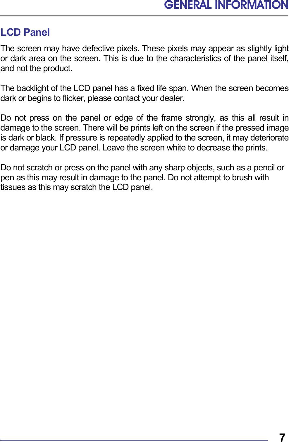
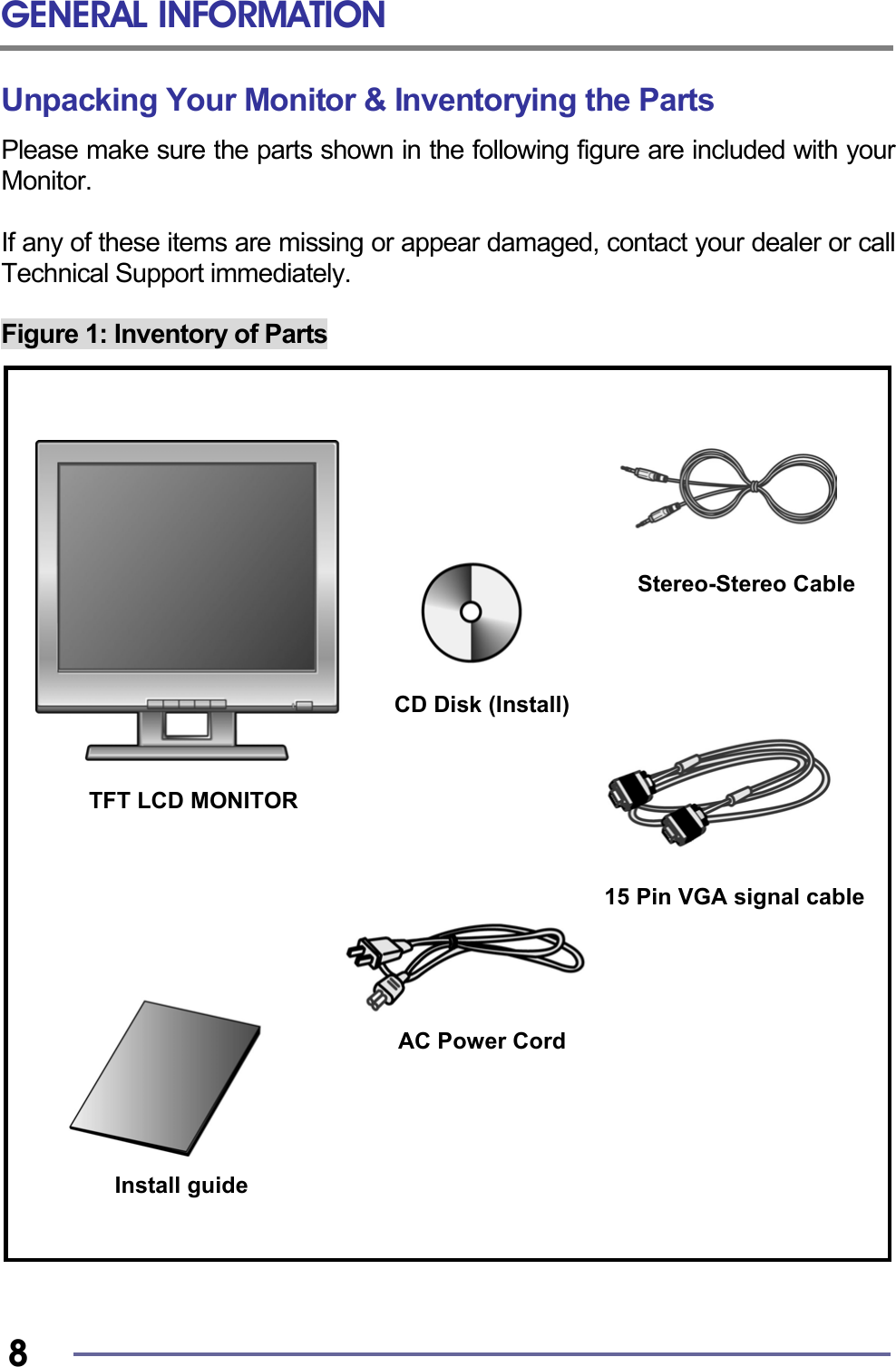

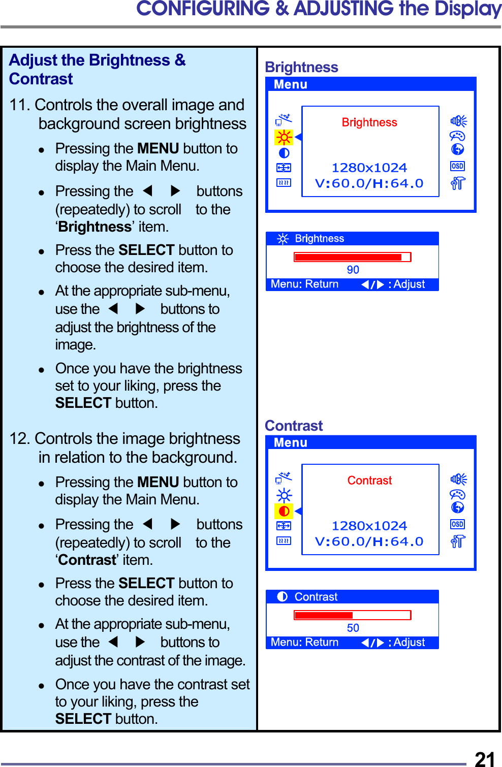
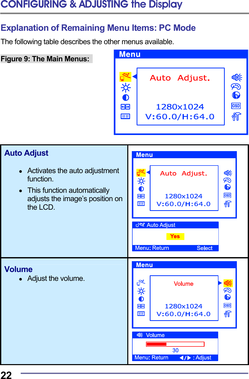
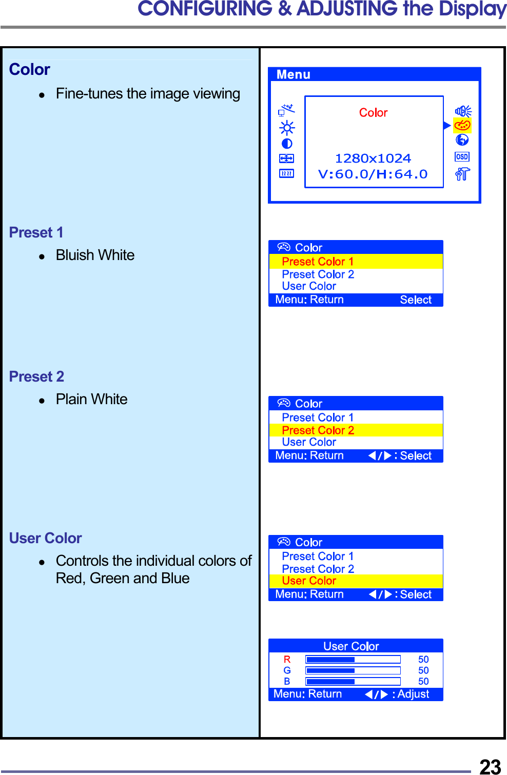
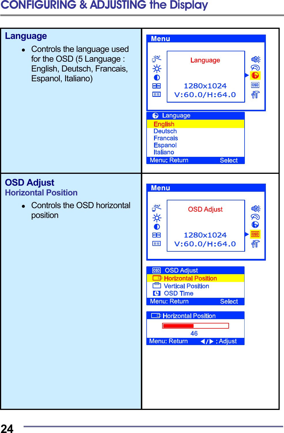
![APPENDIX 30 CT1704 Specifications (Type : S0H) Type 17" (43.18Cm) viewable diagonal TFT type, HT17E11(Hydis) Pixel pitch 0.264 mm (H) x 0.264 mm (V) Viewable angle (CR ≥ 5) Horizontal : ± 80˚ (Left/Right), TN Wide Angle Vertical : +50˚ / -70˚ (Up/Down) LCD viewable size Glass surface Anti-Glare, Hard-Coating (3H) Contrast ratio 500:1 (Typical) Response time 20ms (6ms [Rising] + 14ms [Falling]) Display mode Normally white Brightness 280 cd/ m2 (Max) INPUT VGA RGB Analog, H/V Separate (LVDS) Fh : 31 to 82 KHz Fv : 56 to 75 Hz Input resolution From VGA up to 1280 x 1024 at 60Hz I/O Connectors VGA 15-pin D-sub, DC Power in Stereo Audio In / Out Power AC 100~240V, 50/60Hz Input 12V, 5A Max DC Output User controls Brightness, Contrast, Color, Color Temperature, Auto-Adjustment, Clock, Phase, H/V Position, 5 OSD Language , Volume , Reset Displayable color 16.7 M (Full Color) Displayable area 337.92mm (H) x 270.336mm (V) Operation 0°C ~ 40°C (32°F ~ 104°F) Temperature Storage -20°C ~ 60°C (-4°F ~ 140°F) Dimensions Physical 402.5mm (W) x 420.0mm (H) x 181.0mm (D) Net 5.1Kg (11.24lbs) Weight Gross 6.9Kg (15.21lbs) Regulations MIC, UL/cUL, CE, FCC-B, VCCI, TCO95, ISO13406-II, EPA Energy Star Plug & play VESA DDC 2B Power management VESA DPMS Compatible Option -](https://usermanual.wiki/CORNEA-TECHNOLOGY/CT1704/User-Guide-275044-Page-32.png)