COSMED Srl COSMED-K5 Wearable metabolic system User Manual
COSMED Srl Wearable metabolic system
User Manual
COSMED does not assume any liability for end user interpretation of this user manual or for casual or consequential damages in connection with the
provision, representation or use of this documentation.
No parts of this manual may be reproduced or transmitted in any form without the expressed written permission of COSMED Srl.
Each copy of the COSMED Software can only be installed on one computer.
Excel is a registered trademark of Microsoft Corporation.
DBIII is a registered trademark of Bordland International Inc.
Lotus 123 is a registered trademark of Lotus Development Corporation.
K5 User manual, I Edition
05/2015
Copyright © 2014 COSMED
COSMED Srl - Italy
http://www.cosmed.com
Part N. C04255-02-91

Table of contents
Table of contents .................................................................................................................................................................................. 3
Getting started ..................................................................................................................................................................................... 9
Important notices .............................................................................................................................................................................................. 10
Intended use ............................................................................................................................................................................................... 10
Warnings .................................................................................................................................................................................................... 10
Contraindications .............................................................................................................................................................................................. 12
Contraindications for Exercise testing .......................................................................................................................................................... 12
Absolute contraindications.......................................................................................................................................................................... 12
Relative contraindications ........................................................................................................................................................................... 12
Environmental condition of use ......................................................................................................................................................................... 13
EMC ................................................................................................................................................................................................................... 14
Overview of the manual..................................................................................................................................................................................... 18
System overview ............................................................................................................................................................................................... 19
Portable unit ............................................................................................................................................................................................... 19
Bluetooth PC module (option)..................................................................................................................................................................... 19
Battery charger and batteries ...................................................................................................................................................................... 20
Turbine flowmeter, optoelectronic reader and wind cover .......................................................................................................................... 20
Face mask and head cap.............................................................................................................................................................................. 20
Optoelectronic reader and wind cover ......................................................................................................................................................... 21
HR probe ..................................................................................................................................................................................................... 21
Oximeter (option) ....................................................................................................................................................................................... 21
Pressure regulator for calibration (option) .................................................................................................................................................. 21
USB cable .................................................................................................................................................................................................... 22
Earphones ................................................................................................................................................................................................... 22
O2 sensor ..................................................................................................................................................................................................... 22
Power supply .............................................................................................................................................................................................. 22
System warm-up ............................................................................................................................................................................................... 23
Installation ........................................................................................................................................................................................ 25
Before starting................................................................................................................................................................................................... 26
Checking the packing contents .................................................................................................................................................................... 26
Device packaging ........................................................................................................................................................................................ 26
K5 standard packaging................................................................................................................................................................................ 26
Optional modules........................................................................................................................................................................................ 27
Packaging of optional modules ................................................................................................................................................................... 27
Long Distance bluetooth module standard packaging ................................................................................................................................. 27
Options/Accessories/Spare parts ........................................................................................................................................................................ 28
Preliminary operations ...................................................................................................................................................................................... 29
Battery charger ........................................................................................................................................................................................... 29
Safety warnings .......................................................................................................................................................................................... 29
Use the charger ........................................................................................................................................................................................... 29

Charging batteries ....................................................................................................................................................................................... 29
Recharge time ............................................................................................................................................................................................. 29
Recalibration ............................................................................................................................................................................................... 30
What is recalibration and why is it needed? ................................................................................................................................................. 30
Portable unit ............................................................................................................................................................................................... 30
Powering ..................................................................................................................................................................................................... 30
Top side ....................................................................................................................................................................................................... 30
Front side .................................................................................................................................................................................................... 31
Bottom side ................................................................................................................................................................................................. 31
Installation .................................................................................................................................................................................................. 31
Turning on and off the unit .......................................................................................................................................................................... 31
Warm up ..................................................................................................................................................................................................... 31
Calibration gas cylinder ............................................................................................................................................................................... 31
Install / replace the O2 sensor ............................................................................................................................................................................. 32
Installation .................................................................................................................................................................................................. 32
Replacement ............................................................................................................................................................................................... 32
Install / replace the battery ................................................................................................................................................................................ 33
Installation .................................................................................................................................................................................................. 33
Replacement ............................................................................................................................................................................................... 33
Patient’s preparation ......................................................................................................................................................................................... 34
Assemble the mask and the flowmeter ........................................................................................................................................................ 34
Fixing the K5 to the subject ......................................................................................................................................................................... 34
Fixing HR elastic belt on the subject ............................................................................................................................................................. 35
Fixing the mask to the subject’s face ............................................................................................................................................................ 35
Positioning ECG electrodes (if an ecg is used) ............................................................................................................................................... 35
Connecting the K5 to the PC ............................................................................................................................................................................... 37
Bluetooth connection .................................................................................................................................................................................. 37
USB connection ........................................................................................................................................................................................... 37
How to contact COSMED ..................................................................................................................................................................................... 38
Complaints, feedback and suggestions ........................................................................................................................................................ 38
K5 Operation ...................................................................................................................................................................................... 39
K5 Operating modes ........................................................................................................................................................................................... 40
Holter Data Recorder ................................................................................................................................................................................... 40
Telemetry Data Transmission ....................................................................................................................................................................... 40
Laboratory Station ....................................................................................................................................................................................... 40
User interface ..................................................................................................................................................................................................... 41
The four keys ............................................................................................................................................................................................... 41
Settings.............................................................................................................................................................................................................. 42
International ............................................................................................................................................................................................... 42
System ........................................................................................................................................................................................................ 42
IntelliMET (option) ...................................................................................................................................................................................... 42
Utility ................................................................................................................................................................................................................. 43
Database ..................................................................................................................................................................................................... 43
Search into the database ............................................................................................................................................................................. 43
Backup the database ................................................................................................................................................................................... 43
Erase the database ...................................................................................................................................................................................... 43
Consult the database status ......................................................................................................................................................................... 43
4 - Table of contents - Important notices

Control Panel .............................................................................................................................................................................................. 43
Navigation .................................................................................................................................................................................................. 43
Calibration ......................................................................................................................................................................................................... 45
Calibration frequency .................................................................................................................................................................................. 45
Flowmeter calibration ................................................................................................................................................................................. 45
Perform a turbine calibration ...................................................................................................................................................................... 45
Preface to the analyzers calibration ............................................................................................................................................................. 45
Reference Gas calibration ............................................................................................................................................................................ 46
Room Air calibration ................................................................................................................................................................................... 46
Delay calibration ......................................................................................................................................................................................... 46
Recommendations for exercise testing .............................................................................................................................................................. 48
Evaluation of the cardiorespiratory function ................................................................................................................................................ 48
Precautions ................................................................................................................................................................................................. 48
Laboratory .................................................................................................................................................................................................. 48
Ending the test............................................................................................................................................................................................ 48
Preparing the patient .................................................................................................................................................................................. 48
Before testing ............................................................................................................................................................................................. 48
Patient assent ............................................................................................................................................................................................. 48
Ending the test............................................................................................................................................................................................ 48
Performing a test ............................................................................................................................................................................................... 49
Download a test on the PC ................................................................................................................................................................................. 50
GPS .................................................................................................................................................................................................................... 51
GPS initialisation ......................................................................................................................................................................................... 51
System maintenance .......................................................................................................................................................................... 53
System maintenance ......................................................................................................................................................................................... 54
Cleaning and disinfecting .................................................................................................................................................................................. 55
Prevention of infection transmission ........................................................................................................................................................... 55
Transmission to technicians ........................................................................................................................................................................ 55
Cross-contamination ................................................................................................................................................................................... 55
Tuberculosis ................................................................................................................................................................................................ 55
Haemoptysis and oral lesions ...................................................................................................................................................................... 55
Other known transmissible infectious diseases............................................................................................................................................ 55
Disposable in-line filters.............................................................................................................................................................................. 55
Other precautions and warnings ................................................................................................................................................................. 55
Introduction ................................................................................................................................................................................................ 56
Cleaning...................................................................................................................................................................................................... 56
Cleaning Agents/supplies............................................................................................................................................................................ 56
Standard cleaning procedure ...................................................................................................................................................................... 56
Disinfection ................................................................................................................................................................................................. 57
Preparing the disinfecting solution ............................................................................................................................................................. 57
The turbine flowmeter ................................................................................................................................................................................ 57
Cleaning the turbine ................................................................................................................................................................................... 57
Disinfecting the ID28 turbine ...................................................................................................................................................................... 57
Precautions to take when cleaning, disinfecting and drying the turbine...................................................................................................... 58
VO2max mask .............................................................................................................................................................................................. 58
Disassembling the mask .............................................................................................................................................................................. 58
Cleaning the mask ...................................................................................................................................................................................... 58
Table of contents - Important notices - 5

Disinfecting the mask .................................................................................................................................................................................. 58
Sterilizing the mask ..................................................................................................................................................................................... 59
Reassembling the mask and components .................................................................................................................................................... 59
Cleaning the headcap assembly ................................................................................................................................................................... 59
Sampling line maintenance (Permapure) ........................................................................................................................................................... 60
Inspections ......................................................................................................................................................................................................... 61
Appendix ........................................................................................................................................................................................... 63
Declaration of conformity ................................................................................................................................................................................... 64
Service - Warranty.............................................................................................................................................................................................. 65
Warranty and limitation of liability .............................................................................................................................................................. 65
Return goods policy for warranty or non warranty repair ............................................................................................................................. 65
Repair Service Policy .................................................................................................................................................................................... 65
Privacy Information ............................................................................................................................................................................................ 67
Personal data treatment and purposes ........................................................................................................................................................ 67
How your personal data is treated ............................................................................................................................................................... 67
Consent ....................................................................................................................................................................................................... 67
Holder of the personal data ......................................................................................................................................................................... 67
Customer rights ........................................................................................................................................................................................... 67
Disposing of electrical equipment ...................................................................................................................................................................... 68
Safety and conformity ........................................................................................................................................................................................ 69
Safety .......................................................................................................................................................................................................... 69
EMC ............................................................................................................................................................................................................. 69
Telemetry .................................................................................................................................................................................................... 69
Quality Assurance ........................................................................................................................................................................................ 69
Medical Device Directive (CE mark) .............................................................................................................................................................. 69
FCC .............................................................................................................................................................................................................. 69
Technical features .............................................................................................................................................................................................. 70
Portable Unit ............................................................................................................................................................................................... 70
Battery charger Unit .................................................................................................................................................................................... 70
Flowmeter ................................................................................................................................................................................................... 70
Oxygen Sensor (O2) ...................................................................................................................................................................................... 70
Carbon Dioxide Sensor (CO2) ....................................................................................................................................................................... 70
Humidity absorber ....................................................................................................................................................................................... 70
Power Supply (mains AC/DC adapter) .......................................................................................................................................................... 70
Power Supply (battery charger) ................................................................................................................................................................... 71
Battery ........................................................................................................................................................................................................ 71
Environmental Sensors ................................................................................................................................................................................ 71
Wireless Connectivity .................................................................................................................................................................................. 71
Navigation & Motion Sensors ....................................................................................................................................................................... 71
Calculations references....................................................................................................................................................................................... 72
VO2 and VCO2 ............................................................................................................................................................................................... 72
Anaerobic Threshold (modified V-Slope) ..................................................................................................................................................... 72
References ................................................................................................................................................................................................... 72
Oxygen Kinetics ........................................................................................................................................................................................... 72
References ......................................................................................................................................................................................................... 73
Gas Exchange............................................................................................................................................................................................... 73
Indirect Calorimetry ..................................................................................................................................................................................... 73
6 - Table of contents - Important notices

Sub-maximal exercise testing ..................................................................................................................................................................... 73
Oximeter ..................................................................................................................................................................................................... 73
Table of contents - Important notices - 7
Getting started

Important notices
Intended use
The measurement of oxygen uptake during sport or real life activities is of great interest for the development of training programs and the study of
their effects on elite athletes or for assessing the efficacy of a rehabilitation therapy.
A common method for assessing the effects of endurance training is the monitoring of various respiratory parameters during submaximal exercise.
One difficulty to achieve this goal during sport that cannot be simulated in the laboratory is to use a reliable and valid portable system to measure
VO2 and VCO2 in a field setting.
Such a portable apparatus may also be useful to determine the energy cost of many sport and real life activities.
K5 is an electrical medical device designed for the measurement of cardio respiratory and physiological parameters at rest and during exercise on
spontaneously breathing human subjects from the age of 3 and older and animals within compatible measurement ranges.
Note: When used on animals, K5 is not considered a medical device according to the current regulations. In case,
please contact COSMED in order to obtain further information about the use of the device and accessories (masks,
flowmeters, etc…).
It is to be used by physicians or by trained personnel on a physician responsibility.
Note: K5 have not to be intended as a monitoring device. It is not intended to be used for continuous surveillance of
vital physiological processes, but only to obtain readings of different physiological signals and parameters in routine
check-ups.
Caution: Federal law restricts this device to be sold by the order of a physician.
This equipment is intended to be used for the following applications:
• Formulating of a lung pathology diagnosis.
• Assisting with human physiology studies.
• Contributing to sports medicine applications.
COSMED Srl is not responsible for incidents which occur due to improper use of this device. Examples include:
• Operation of the device by unqualified individuals.
• Use of the device not indicated by this manual.
• Not complying with the precautions and instructions described in this manual.
Warnings
The device, program algorithms and presentation of the measured data has been developed in accordance with the specifications outlined by the
ATS (American Thoracic Society) and ERS (European Respiratory Society). Additional international references have also been applied where
applicable. All bibliography references are reported in the Appendix.
This User Manual has been developed in accordance with the Class IIa European Medical Device Directive requirements.
The precautions listed below should be noted before operating the device to ensure the safety of the user.
1. This User Manual should always be available as a reference when testing.
2. The following standards should be applied to ensure the accuracy of individual test results:
• Accessories should only be used as described in this manual. The manufacturer does not warranty any non-authorized accessories used by
the end user. The manufacturer may offer suggestions while using such accessories and the complications they could cause;
• Repairs or modifications of the device should ONLY be carried out by qualified and trained personnel;
• Environmental and electrical conditions in which the device operates should be in compliance with the specifications of this manual.
• Equipment maintenance, inspections, disinfection and cleaning should be as described in this manual.
3. Before powering on the system, the power cords and plugs should be inspected. Damaged electrical parts must be replaced immediately by
authorized personnel.
4. Large gas cylinders provided by the manufacturer or purchased by the customer must be secured with cylinder safety chains or safety stands as
required by local law.
5. After removing the protective cap of the cylinder you should inspect the cylinder valve for damaged threads, dirt, oil and/or grease. Any dust or
dirt should be removed and the cylinder should not be used if oil or grease is present.
10 - Getting started - Important notices
6. You should ensure that the pressure regulator is chemically and physically compatible with the intended gas cylinder before installation. The
regulator must be properly connected. Note the pressure gauge for the regulator. The physical condition of the regulator, threads and fittings
should also be examined prior to installation. Any dust or dirt on the regulator or cylinder valve should be removed with a clean cloth. The
regulator should not be installed on a cylinder valve if grease or oil is present.
7. The cylinder and pressure regulator must be closed before disconnecting the cylinder from the device.
8. Batteries must be removed from the device when it is not used for a long time.
9. Internal backup battery can be replaced by trained authorized personnel only. The user can only replace the external battery as described in the
dedicated section. Risk of excessive temperatures, fire or explosion.
10. Residue and other contaminants in the breathing circuit pose a safety risk to the patient during testing procedures. Aspiration of contaminants
can be potentially life-threatening. If the recommended disposable anti-bacterial filters are not used, you must disinfect each part coming into
contact with the patient and patient’s breath prior to each test.
11. The cleaning procedures and inspections in the System Maintenance section should be performed prior to each test.
12. This device should not be used in the presence of flammable anaesthetics. This is not an AP or APG device (according to the EN 60 601-1
definitions).
13. The device should not come near any heat or flame sources, flammable or inflammable liquids or gases and explosive properties.
14. The device should not be used in conjunction with any other medical device unless that device is recommended by the manufacturer.
15. The device should be used with a computer with electromagnetic compatibility, CE marking and low radiation emission displays.
16. The PC connected to the device must be compliant with EN 60601-1 by means of an isolation transformer.
17. Precautions regarding EMC should be taken prior to installation and can be noted in the section EMC.
18. Portable and mobile RF communication equipment may interfere with the performance of the device.
19. Only the cable and accessories supplied with the equipment should be used with the device. The use of accessories and/or cables other than
those supplied may result in increased emissions or decreased immunity of the equipment.
20. The device should not be used adjacent to or stacked with other equipment. If this is necessary, you must verify that the device continues to
operate normally in the configuration in which it will be used.
21. The operator cannot simultaneously touch the battery charger and the subject.
22. The TTL ecg connector is not optically insulated: an external device (ecg) can be connected to K5 only through the optional cable C04109-01-12.
Do not use other cables since they cannot guarantee this insulation and they can cause serious injuries to the patient.
23. If the product is damaged (e.g. as a result for a free fall), the IP degree of the device itself can be altered. Please do not use K5 and send it back
to COSMED or to an authorized center for a technical service.
24. The graphical symbols used with the device are described below:
Applied part type BF (EN60601-1) Locked
Class II device (EN60601-1)
Unlocked
CE mark (compliance with MDD 93/42) Recording
Device code
ON/OFF
/
Serial number
BACK/CHECK key
HR probe / TTL connector HOME/MARKER key
USB connector
Read the user manual
Power connector (dc)
Warning
Getting started - Important notices- 11

Contraindications
Performing forced expiratory manoeuvres involved in spirometry testing may be contraindicated in certain conditions.
Contraindications for Exercise testing
Absolute contraindications
• Acute MI (within 2 days)
• High-risk unstable angina
• Uncontrolled cardiac arrhythmias causing symptoms of hemodynamic compromise
• Active endocarditis
• Symptomatic severe aortic stenosis
• Decompensated symptomatic heart failure
• Acute pulmonary embolus or pulmonary infarction
• Acute noncardiac disorder that may affect exercise performance or be aggravated by exercise (eg, infection, renal failure, thyrotoxicosis)
• Acute myocarditis or pericarditis
• Physical disability that would preclude safe and adequate test performance
• Inability to obtain consent
Relative contraindications
• Left main coronary stenosis or its equivalent
• Moderate stenotic valvular heart disease
• Electrolyte abnormalities
• Tachyarrhythmias or bradyarrhythmias
• Atrial fibrillation with uncontrolled ventricular rate
• Hypertrophic cardiomyopathy
• Mental impairment leading to inability to cooperate
• High-degree AV block
Note: Relative contraindications can be superseded if benefits outweigh risks of exercise.
Read carefully the exercise testing chapter.
12 - Getting started - Contraindications

Environmental condition of use
COSMED units should not be operated near explosive substances.
Equipment should not be installed near electrical or magnetic devices such as x-ray equipment, transformers or power lines. These devices could
create electrical interferences when performing testing procedures. COSMED devices are not AP or APG units (according to EN 60601-1) and should
never be operated in the presence of flammable anaesthetic mixtures.
COSMED equipment should be operated under normal environmental temperatures and conditions which are defined as follows [IEC 60601-1/EN
60601-1]:
• Temperatures range: 10°C (50°F) and 40°C (104°F).
• Relative humidity range: 30% to 99%.
• Atmospheric Pressure range: altitude from sea level to 4850m.
Note: The K5 Power Supply AC/DC Adapter (C04118-01-30) can be used up to 3000m, the Dual Battery Charger
AC/DC Adapter (C04267-01-10) can be used up to 2000m.
• Avoid operating equipment in the presence of noxious fumes or in dusty environments.
• Do not place units near heat sources.
• Cardiopulmonary resuscitation equipment should be accessible in the case of an emergency.
• Adequate floor space and easy access to the patient during exercise testing is necessary.
• Adequate ventilation should be maintained in the room the testing is performed.
Getting started - Environmental condition of use- 13

EMC
Guidance and manufacturer’s declaration - electromagnetic emissions
The device is intended for use in the electromagnetic environment specified below. The customer or the user of the device should assure that it
is used in such an environment.
Emissions test Compliance Electromagnetic environment – guidance
RF emissions
CISPR 11
Group 1 The device
uses RF energy only for its internal function. Therefore, its RF emissions are very
low and are not likely to cause any interference in nearby electronic equipment.
RF emissions
CISPR 11
Class B The device is suitable for use in all establishments, including domestic establishments and
those directly connected to the public low-voltage power supply network that supplies
buildings used for domestic purposes.
Harmonic Emission
IEC 61000-3-2
Class A
Voltage
Fluctuations /
Flicker Emission
IEC 61000-3-3
Complies
14 - Getting started - EMC

Guidance and manufacturer’s declaration - electromagnetic immunity
The device is intended for use in the electromagnetic environment specified below. The customer or the user of the device should assure that it
is used in such an environment.
Immunity test Test level
IEC 60601-1
Compliance level Electromagnetic environment – guidance
Electrostatic discharge
(ESD)
IEC 61000-4-2
±6 kV contact
±8 kV air
±6 kV contact
±8 kV air
Floors should be wood, concrete or ceramic tile. If floors are
covered with synthetic material, the relative humidity should
be at least 30%.
Electrical fast
transient/burst
IEC 61000-4-4
±2 kV for power
supply lines
±1 kV for
input/output lines
±2 kV for power
supply lines
±1 kV for
input/output lines
Mains power quality should be that of a typical commercial or
hospital environment.
Surge
IEC 61000-4-5
±1 kV differential
mode
±2 kV common
mode
±1 kV differential
mode
±2 kV common mode
Mains power quality should be that of a typical commercial or
hospital environment.
Voltage dips, short
interruptions and voltage
variations on power supply
input lines
IEC 61000-4-11
<5% UT
(>95% dip in UT) for
0.5 cycles
40% UT
(60% dip in UT) for 5
cycles
70% UT
(30% dip in UT) for 25
cycles
<5% UT
(>95% dip in UT) for
5 sec
<5% UT
(>95% dip in UT) for
0.5 cycles
40% UT
(60% dip in UT) for 5
cycles
70% UT
(30% dip in UT) for 25
cycles
<5% UT
(>95% dip in UT) for
5 sec
Mains power quality should be that of a typical commercial or
hospital environment. If the user of the device requires
continued operation during power mains interruptions, it is
recommended that the device
be powered from an
uninterruptible power supply or a battery.
Power frequency (50/60
Hz) magnetic field
IEC 61000-4-8
3 A/m 3 A/m
Power frequency magnetic fields should be at levels
characteristic of a typical location in a typical commercial or
hospital environment.
Nota: UT is the a.c. mains voltage prior to application of the test level.
Getting started - EMC- 15
Guidance and manufacturer’s declaration - electromagnetic immunity
The device is intended for use in the electromagnetic environment specified below. The customer or the user of the device should assure that it
is used in such an environment.
Immunity test Test level
IEC 60601-1
Compliance level Electromagnetic environment – guidance
Conducted RF
IEC 61000-4-6
Radiated RF
IEC 61000-4-3
3 Veff
150 kHz to
80 MHz
3 V/m
80 MHz to
2.5 GHz
3 V
3 V/m
Portable and mobile RF communications equipment should be
used no closer to any part of the device, including cables, than
the recommended separation distance calculated from the
equation applicable to the frequency of the transmitter
Recommended separation distance
d=1.17
P
d=1.17
P
80 MHz to 800 MHz
d=2.33
P
800 MHz to 2.5 GHz
where P
is the maximum output power rating of the
transmitter in watts (W) according to the transmitter
manufacturer and d
is the recommended separation distance in
metres (m).
Field stre
ngths from fixed RF transmitters, as determined by an
electromagnetic site surveya
, should be less than the
compliance level in each frequency rangeb.
Interference may occur in the vicinity of equipment marked
with the following symbol:
Notes:
(1) At 80 MHz, the higher frequency range applies.
(2) These guidelines may not apply in all situations. Electromagnetic propagation is affected by absorption and reflection from structures,
objects and people.
a Field strengths from fixed transmitters, such as base
stations for radio (cellular/cordless) telephones and land mobile radios, amateur radio,
AM and FM radio broadcast and TV broadcast cannot be predicted theoretically with accuracy. To assess the electromagnetic environment
due to fixed RF transmitters, an
electromagnetic site survey should be considered. If the measured field strength in the location in which the
device is used exceeds the applicable RF compliance level above, the device should be observed to verify normal operation. If abnormal
performance is observed, additional measures may be necessary, such as reorienting or relocating the device.
b Over the frequency range 150 kHz to 80 MHz, field strengths should be less than 3 V/m
16 - Getting started - EMC

Recommended separation distances between portable and mobile RF communications equipment and the device
The device is intended for use in an environment in which radiated RF disturbances are controlled. The customer or the user of the device can
help prevent electromagnetic interference by maintaining a minimum distance between portable and mobile RF communications equipment
(transmitters) and the device as recommended below, according to the maximum output power of the communications equipment.
Rated maximum output
power of transmitter
(W)
Separation distance according to frequency of transmitter
(m)
150 kHz to 80 MHz
d=1.17
P
80 MHz to 800 MHz
d=1.17
P
800 MHz to 2.5 GHz
d=2.33
P
0.01 0.12 0.12 0.23
0.1 0.37 0.37 0.74
1 1.17 1.17 2.33
10 3.70 3.70 7.38
100 11.70 11.70 23.33
For transmitters rated at a maximum output power not listed above, the recommended separation distance d in metres (m) can be determined
using the equation applicable to the frequency of the transmitter, where P is the maximum outp
ut power rating of the transmitter in watts (W)
according to the transmitter manufacturer.
Notes:
(1) At 80 MHz and 800 MHz, the separation distance for the higher frequency range applies.
(2) These guidelines may not apply in all situations. Electromagnet
ic propagation is affected by absorption and reflection from structures,
objects and people.
Getting started - EMC- 17

Overview of the manual
This manual is organized in the following chapters:
Getting started. Describes the intended use of the device, how to properly use it and features of the unit and accessories.
Installation. Lists the steps required to properly install the device.
K5 Operation: illustrates the functions of the device including managing data and test performance.
System maintenance. Describes system maintenance procedures.
Appendix. Contains information regarding the warranty, treatment of personal data, reference standards, technical features, predicted values and
bibliographic references.
Software and test execution are described in the Software Manual. We recommend to read both manuals before using this device.
18 - Getting started - Overview of the manual
System overview
The K5 consists of the following main parts:
• Portable unit
• Batteries
• Battery charger
• Flowmeter
• Additional external sensors and devices (HR, oximeter, face masks, etc.).
Some of the parts described below are options and are not included in the standard packaging.
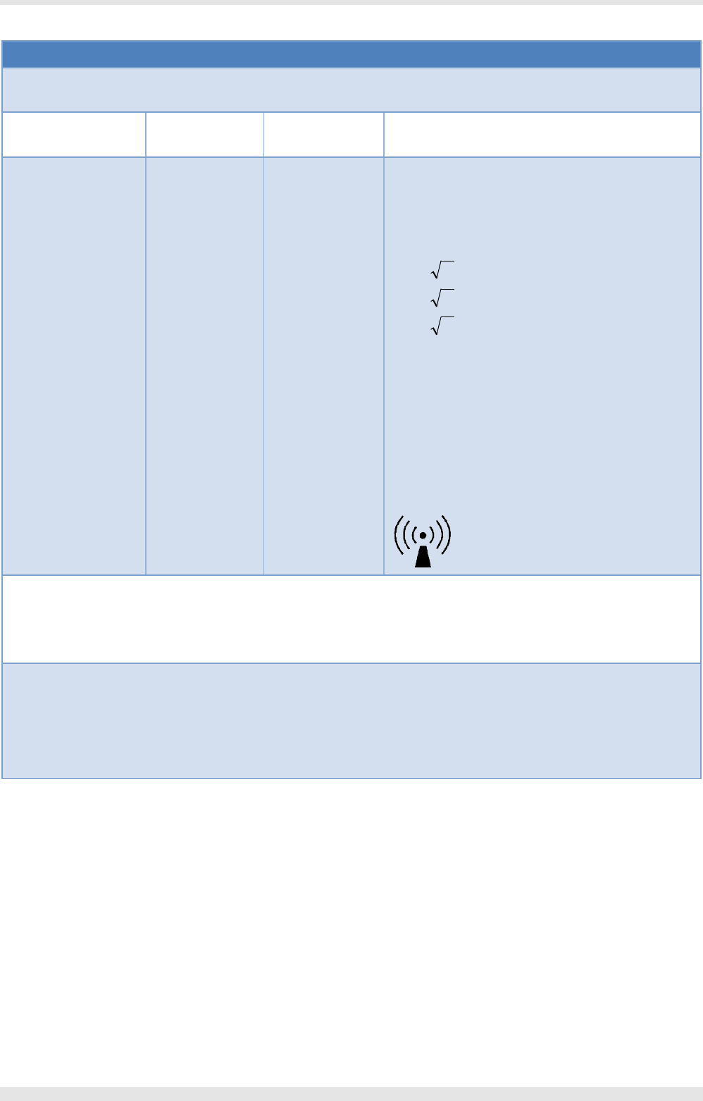
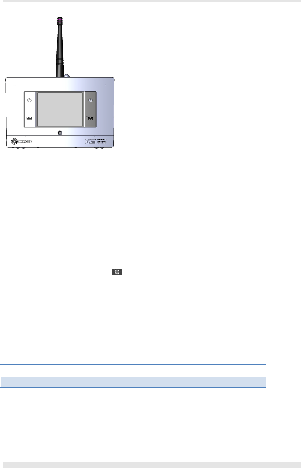
Portable unit
It is fixed to the patient during the test by an anatomic harness. In this configuration, the distance between subject’s body and the transmitting
antenna is more than 25mm. The PU contains the O2 and CO2 analyzers, sampling pump, transmitter, barometric sensors and electronics. It is
powered by the rechargeable battery inside it.
The K5 is provided with a 3.5” touch-screen LCD display with LED-back-lit TFT for optimal viewing in all lighting conditions. The LCD user interface
allows full control on all features under any environment. The touchscreen technology is resistive, so it can be used in outdoor conditions with
either gloves or wet fingers.
Bluetooth PC module (option)
The bluetooth PC module is an option for the K5 Long distance module, and it is used together its antenna on the PC for receiving data from the K5
unit if the standard Bluetooth transmission range cannot be met (approximately over 30-50 meters). It allows communication between the devices
up to 900 meters in line-of-sight)
Getting started - System overview- 19
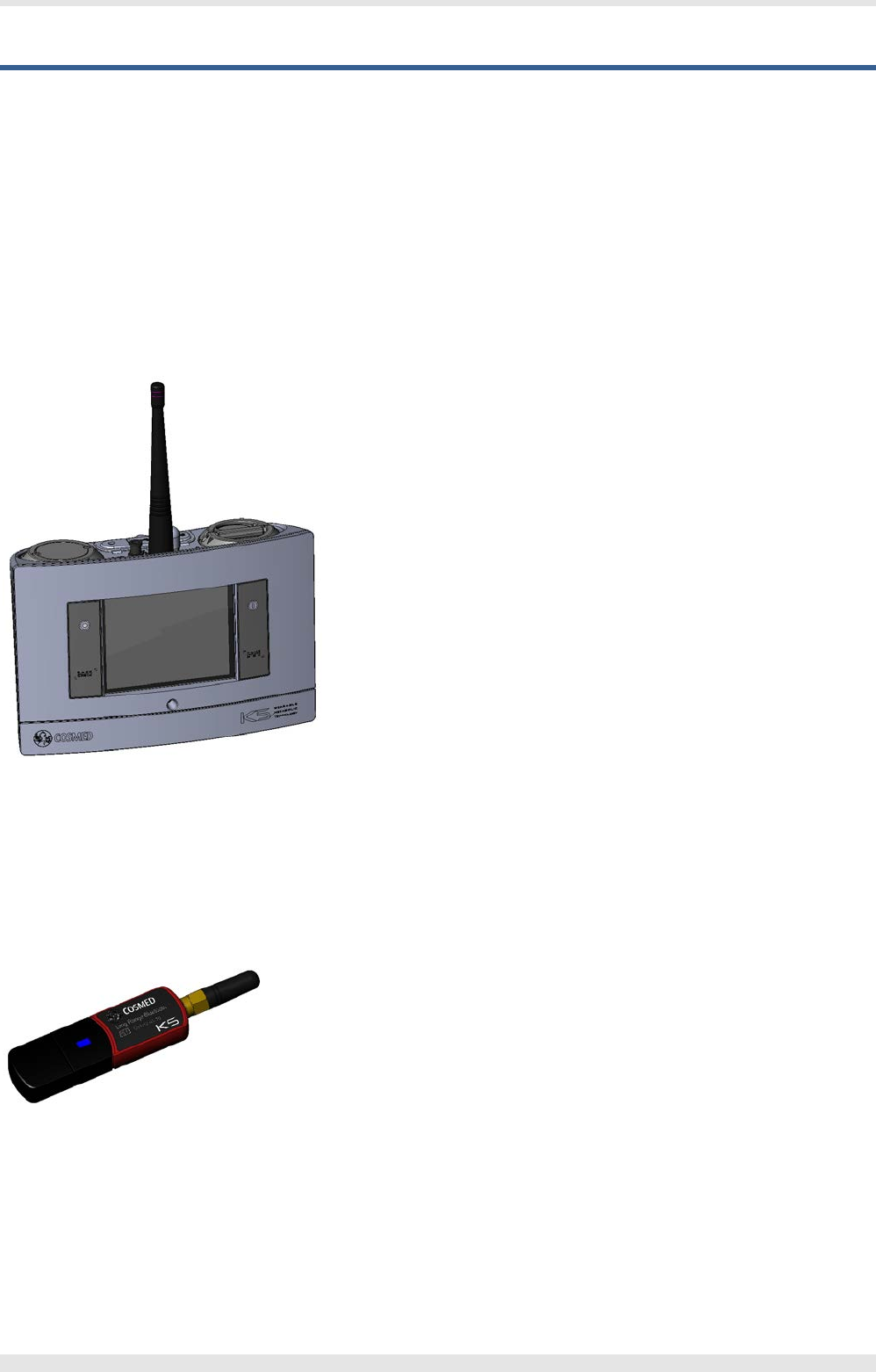
Battery charger and batteries
The battery charger allows the simultaneous charge of two batteries. Each battery can power the portable unit for about 4 hours.
Turbine flowmeter, optoelectronic reader and wind cover
The turbine flowmeter assembly consists of a bidirectional turbine, an optoelectronic reader and an optional wind cover. The reader measures
infrared light interruptions caused by the spinning blade inside the turbine. The device may be used to measure a wide flow range and is not
affected by ambient conditions (pressure, humidity, room temperature, exhaled gas composition). Daily calibration of the turbine is not necessary,
but calibrations should be performed regularly to assure accurate measurements.
The wind cover is mounted on the reader and it is used for protecting the turbine from the wind (for outdoor applications), in order to avoid errors
due to the wind entering into the turbine.
The flowmeter can be used for all tests.
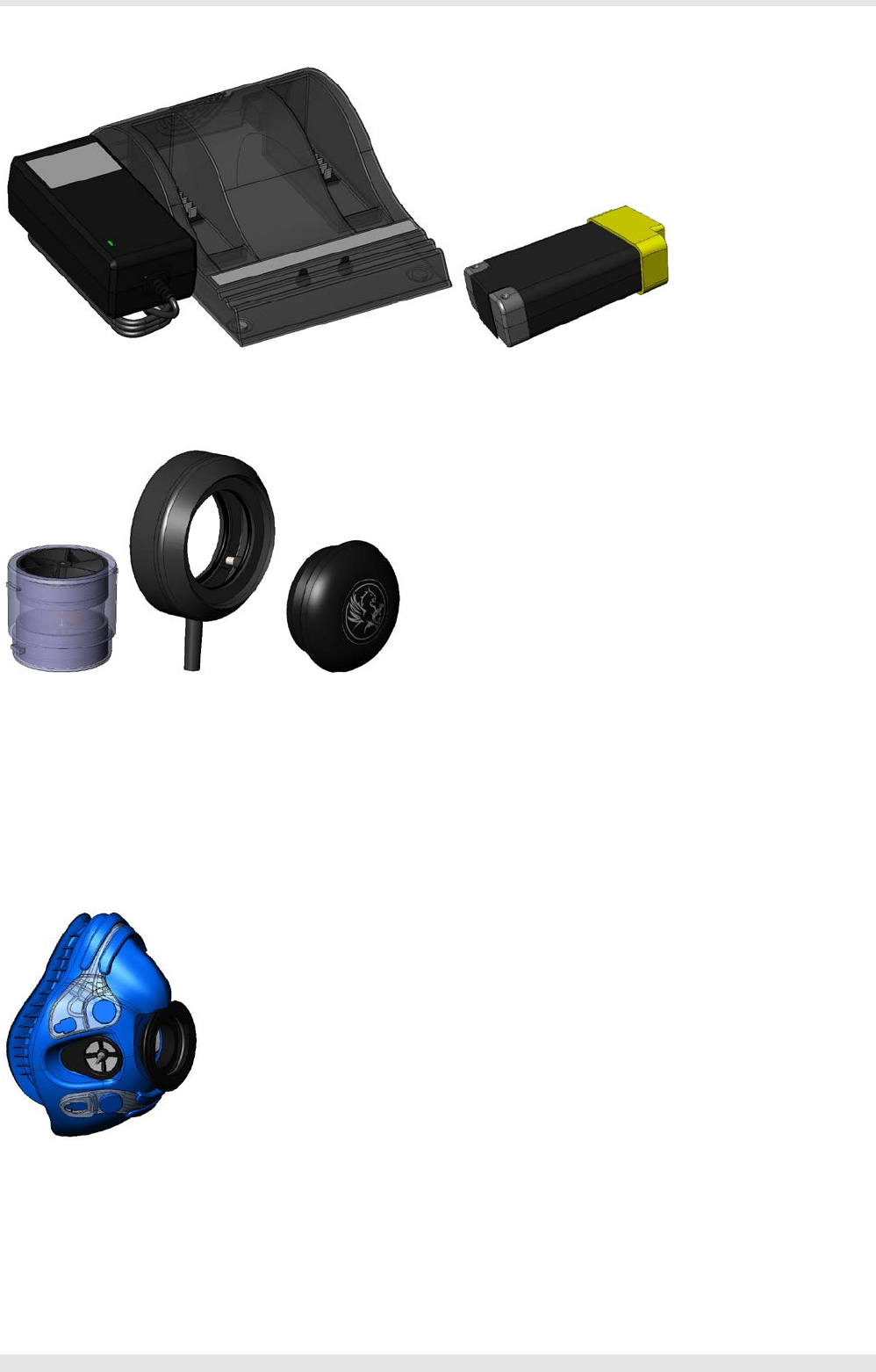
Face mask and head cap
The exercise test masks are made of silicone and may be reused after proper disinfection (see the chapter Maintenance).
These blue masks are available in different sizes and should be assembled the included head cap as shown in the chapter Exercise testing.
20 - Getting started - System overview
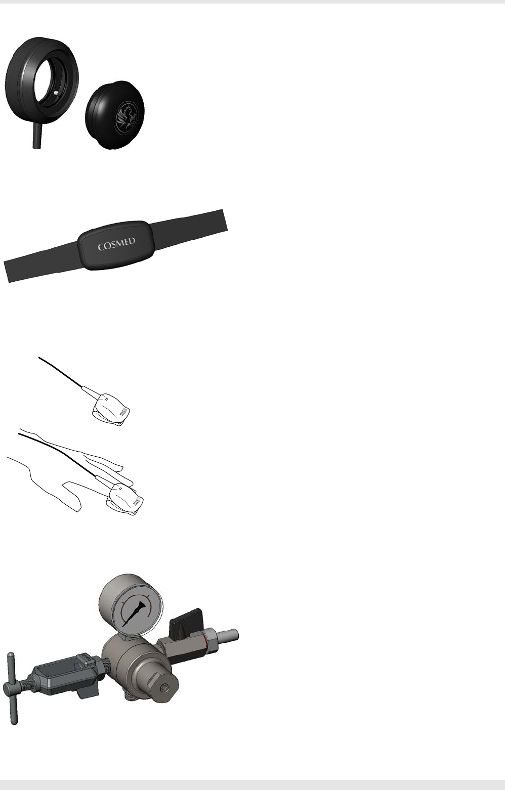
Optoelectronic reader and wind cover
The optoelectronic reader
HR probe
The HR probe consists of two parts that can be fixed by means of automatic buttons: the elastic belt and the transmitter. The belt should be placed
as close as possible to the K5 unit to acquire the most effective communication signal.
Oximeter (option)
The oximeter probe should be placed on the patient’s finger to measure oxygen saturation at rest or during exercise.
Pressure regulator for calibration (option)
The pressure regulator is connected to the calibration cylinder for the calibration of the K5 unit. The gas exiting from the regulator enters directly
into the unit, which measures its concentration and adjust its correction factors in order to achieve the best accuracy.
Getting started - System overview- 21
There are two different pressure regulators, depending on the cylinder connection: CGA 973 and UNI 4410.
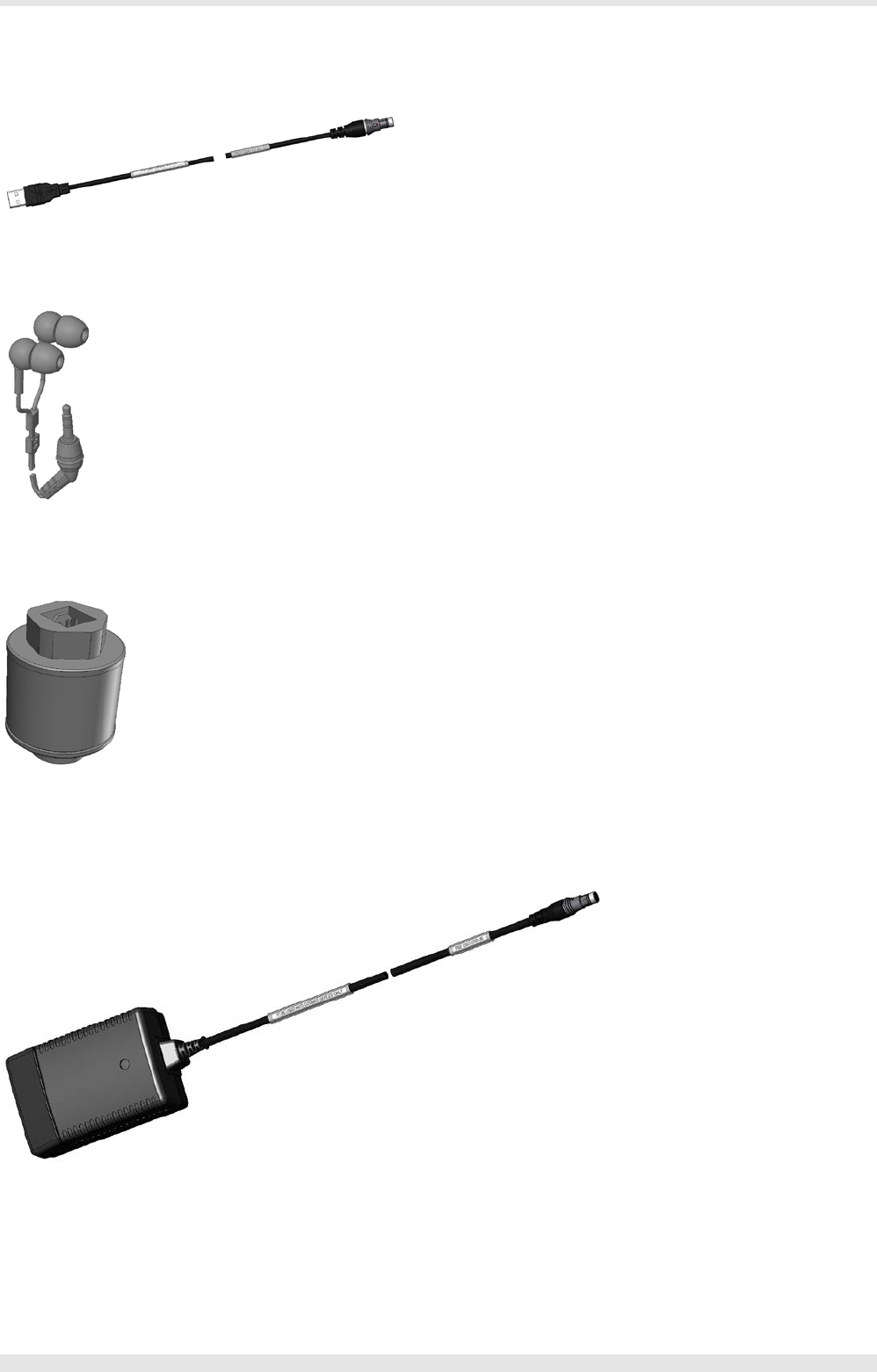
USB cable
The USB cable is used to connect the K5 unit to the PC, for downloading tests or for use the device in laboratory mode.
Earphones
The earphones are used for communicating with the subject in outdoor telemetric applications.
O2 sensor
The O2 sensor (included in the packaging as a spare part) must be installed by the user before starting using the device, and it must be replaced
periodically when exhausted. It measures the O2 concentration in the gas sampled by the device.
Power supply
The power supply AC/DC adapter allows the usage of the device without batteries or while the batteries are charging.
22 - Getting started - System overview

System warm-up
Before using the K5 unit, it must be warmed up for the required amount of time. The warm-up time duration depends on which test is being
performed. The following table displays the warm-up time required for each test:
Test Warm-up time (minutes)
CPET (exercise test) 45
During the warm-up period the device must be powered on, but the software does not need to be open.
Calibration and/or testing procedures should never be performed until the warm-up period has been completed.
Getting started - System warm-up- 23
Installation

Before starting
Before operating the K5 you should inspect the equipment and complete the product registration.
Checking the packing contents
When opening your product you should assure that the package contains all items listed below. If there are any missing or damaged parts you
should contact Cosmed’s technical assistance.
Device packaging
The device is made of a main unit and one or more optional modules. The content of the main unit is listed in the following, the content of the
modules at the end of this section.
K5 standard packaging
Code Quantity Description
C04162-01-04 1 K5 Unit
C04020-01-04 1 K5 Optoelectronic Reader
C04311-01-10 2 K5 Turbine with case (C02120-01-05 turbine, A-170-700-005 case)
C02107-02-08 1 Wind cover
C04254-01-08 2 K5 Permapure Line
C04273-01-05 2 K5 Rechargeable Battery
C04267-01-10 1 Dual Battery Charger AC/DC Adapter
C04118-01-30 1 K5 Power Supply AC/DC Adapter
A-497-900-00x 1 Plug for the power supply adapter (x=2 Australia, x=3, Europe, x=4 USA, x=5 UK)
A-661-200-071 1 HR Belt
A-661-200-070 1 HR Monitor
C04370-01-05 1 K5 Harness Adult
C04117-01-12 1 K5 USB cable
A-471-300-001 1 Waterproof Flex Earphone
C04324-01-10 1 VO2max mask (small)
C04324-02-10 1 VO2max mask (medium)
A-800-900-023 2 VO2max Headgear Adult (Small, Medium)
A-558-250-005 1 O2 sensor
C04286-01-20 1 O2 Sensor Key
C04300-01-20 1 O2 Cap Key
C04309-01-04 1 K5 Case
C04060-01-11 1 PC software
C04255-02-91 1 User manual
26 - Installation - Before starting

Optional modules
Note: The codes and the packaging shown in the tables below refer to the module if purchased together with the K5
unit. If you wish to purchase an optional module separately from the unit, please contact our sales department or our
distributor.
Code Description
C04270-01-11 Long Distance bluetooth module
C04271-02-11 IntelliMet upgrade to BxB gas sampling module
C04272-01-11 Ant+ engine module
Packaging of optional modules
Long Distance bluetooth module standard packaging
Code Quantity Description
C04262-01-10 1 BlueTooth USB Receiver
A-462-100-003 1 Telematic Antenna
Installation - Before starting- 27

Options/Accessories/Spare parts
The following options are available with the K5:
Code Quantity Description
A 860 000 004 1 Calibration cylinder (5% CO2, 16% O2, balance N2)
A-870-150-012 1 Pressure regulator for calibration (CGA 973)
A-870-600-001 1 Pressure regulator for calibration (UNI 4410)
C00600-01-11 1 Calibration syringe 3 litres
C04108-01-06 1 HR Polar receiver
C04109-01-12 1 Optoisolated HR interface (for TTL ecg)
A-497-500-004 1 Battery charger (cigar light adapter)
C04380-01-08 1 K5 Harness Paediatric
C04320-01-08 1 K5 Harness (frontal)
Main spare parts:
Code Quantity Description
C04273-01-05 1 K5 Rechargeable Battery
C04254-01-08 1 K5 Permapure Line
A-558-250-005 1 O2 sensor
C04158-01-10 1 CO2 absorber assembly
28 - Installation - Options/Accessories/Spare parts
Preliminary operations
Before operating the system you should make sure that environmental and operational conditions have been met (see Chapter 1).
Note: The first time you use the device, charge the battery until they are completely charged (see below).
Battery charger
Note: The USB connection (to PC or any other USB devices) doesn’t charge the battery.
Safety warnings
1. Do not expose the charger or power supply to water or liquids. The case it not sealed.
2. Do not open the charger or power supply case. No user serviceable parts are inside.
3. Do not cover the fan exhaust or obstruct the airflow, this will cause overheating.
4. User only the manufacturer’s power supply and observe terminal polarity.
5. Place the charger in a cool spot, away from external heat sources.
6. CAUTION: during recalibration the charger may become warm.
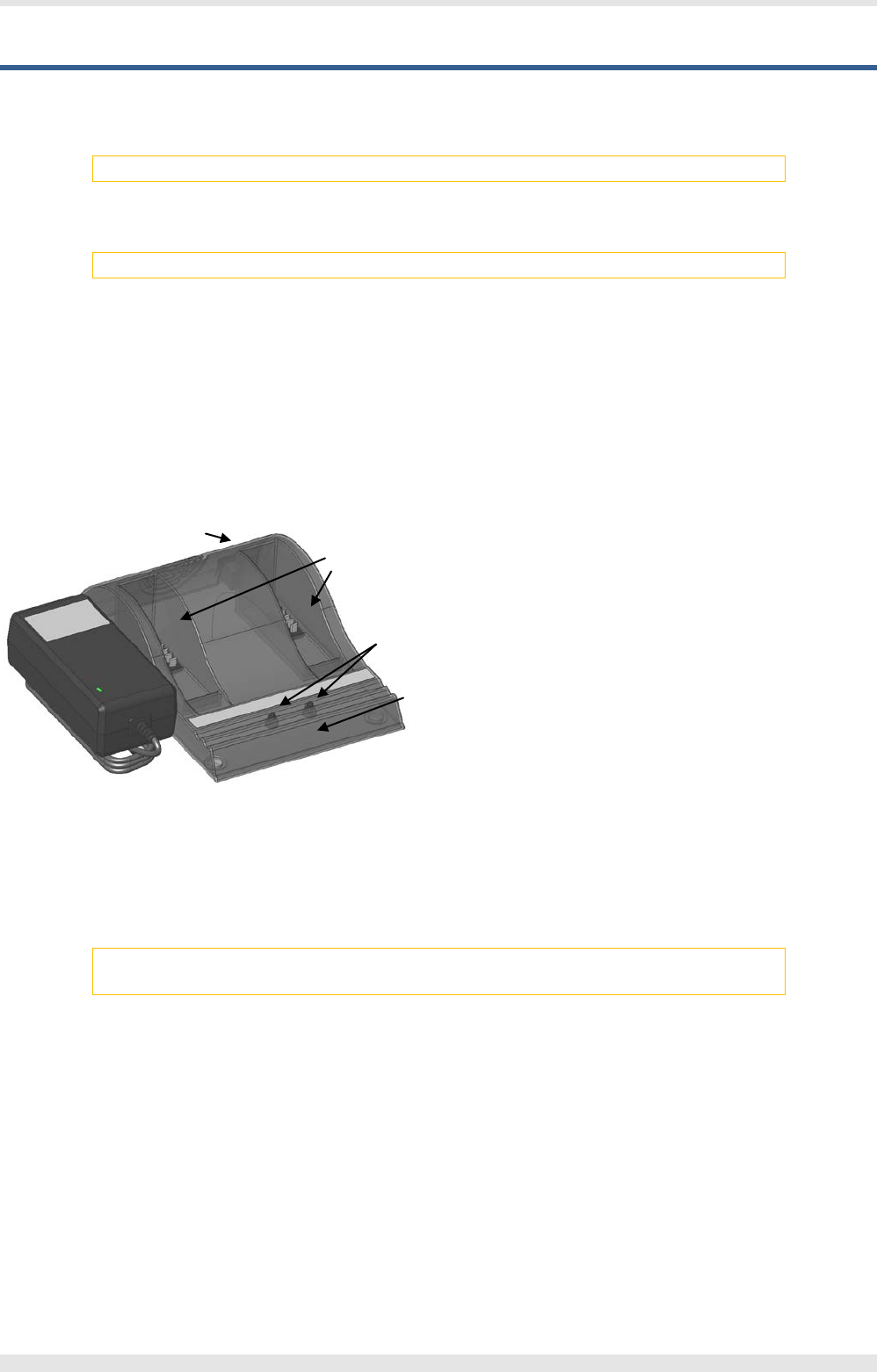
Use the charger
1. DC connector 2. Battery bays 3. Calibration buttons 4. Status window
Place the charger on a flat, level surface, away from source of heat and moisture.
Plug the DC/AC adapter connector from the power supply into the back of the charger and connect the power supply to the mains AC supply using
the cable supplied. All the LEDs will flash momentarily to let you know that power is present.
Charging batteries
Note: The batteries must be replaced when they do not maintain their charge for enough time. Please contact the
technical support.
Place the batteries into either battery bay, ensuring that the 5-way connector is fully seated. The LEDs in the status window will provide status
information and the charger will automatically begin charging.
The status of the battery is indicated by the LEDs visible in the status window:
Green flashing Battery charging Green solid Battery fully charged
Blue flashing Battery in calibration mode Blue solid Battery fuel gauge calibrated
Red flashing Battery fuel gauge in need of recalibration Red solid Error
Recharge time
Each bay is completely independent, and the battery charger can charge two batteries simultaneously.
Battery can be charged in about two hours, while the recalibration procedure requires about 9-11 hours.
1
2
3
4
Installation - Preliminary operations- 29
Recalibration
Recalibration consists of a charge, followed by a calibration discharge. Finally the battery is given a regular charge. A calibration cycle is faster if the
battery is fully charged to begin with.
If fuel gauge recalibration is needed, the red LED on the charger will flash upon insertion of the battery. The user can either calibrate the fuel gauge
and charge the battery, or just charge the battery.
For starting the recalibration, press the calibration button corresponding to the battery to be recalibrated. If the button is not pressed, the charger
will automatically begin to charge the battery. At the end of the calibration the blue LED will stay constant indicating a fully calibrated fuel gauge.
The blue LED will flash to indicate that the battery is undergoing the recalibration cycle. Note that calibration is initiated each time the button is
pressed or each time the battery is removed, so it is not recommended to press the recalibration button part way through the recalibration cycle.
What is recalibration and why is it needed?
As the battery ages and is used, its available capacity shrinks. So, with each cycle, K5 runtime gets a little bit less. A good rule of thumb is that Li-Ion
batteries lose 5% capacity per 100 cycles and 5% per year.
The fuel gauge not only provides the battery’s remaining capacity, it also gives an estimated accuracy figure known as the “Max-Error”. This keeps
track of the overall accuracy of the estimated remaining capacity. Recalibration is used to re-set the fuel gauge to match the actual capacity of the
battery. In this way, even as the battery ages and things change, the accuracy and reliability of the fuel gauge can be retained throughout the life of
the battery.
Portable unit
Powering
The portable unit can be supplied either by the Power supply adapter or by rechargeable batteries. During warm-up, it is recommended to supply it
exclusively by the Power supply adapter in order to save the battery normally used during the test.
The external Power supply adapter can be connected between the AC mains plug and the connector on the top side of the K5 unit and both
powers the unit and charge the battery inside it.
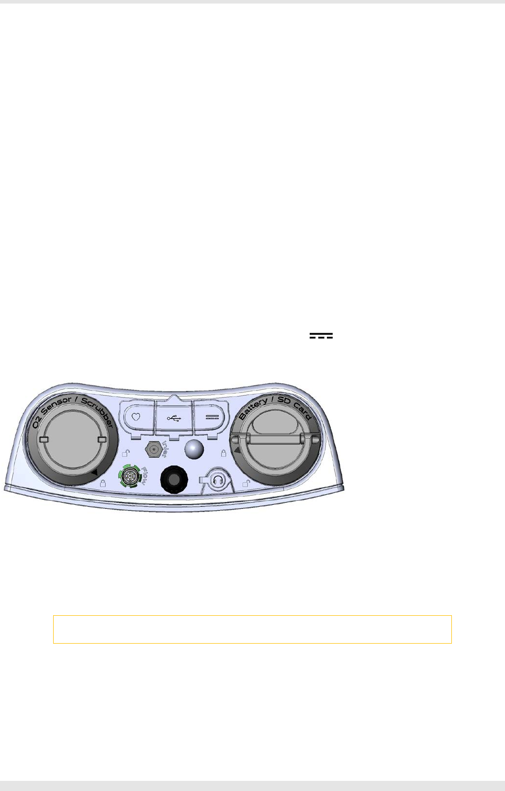
Top side
1. O2 sensor / CO2 absorber slot 2. Flowmeter connector
3.
Antenna 4.
Earphone connector
5. Sampling line connector 6. Air inlet
7. HR Polar receiver / TTL ecg connector (if available) 8. USB connector
9.
Power supply connector 10.
Battery / SD card slot
Warning: In order to obtain the required performances in terms of degree of protection against the ingress of liquids
or other particles (IP grade) be sure that all the covers are properly placed and closed.
1
2
4
6
7
8
9
10
30 - Installation - Preliminary operations
Front side
1.
Rec key (starts the data acquisition) 2.
BACK/CHECK key (returns to the previous menu or perform a system check)
3. ON/OFF key (turns the device on or off) 4. HOME/MRK key (returns to the home menu or enter a marker during the test)
5. LCD display 6. Humidity sensor
Bottom side
In the bottom side is located a threated slot for connection to a tripod or to the harness.
Installation
In order to start using the device for the first time, please connect the O2 sensor and the battery. Refer to the below sections in order to perform
these operations.
Turning on and off the unit
To turn on or off the device, please press and hold the key for some seconds.
Warm up
The K5 uses O2 and CO2 heated sensors. In order to ensure accurate gas measurements, you must wait at least 45 minutes warm-up time at an
ambient temperature of 20°C. More time is necessary if the environmental temperature is lower. Calibration or testing before warm-up time is
completed, can cause wrong results.
To start the warm-up period, connect the battery to the K5 and turn the unit on.
Calibration gas cylinder
In order to calibrate the sensors you need to have available calibration cylinder with the following gas concentration:
Cylinder Recommended gas mixture
Calibration O2 16%, CO2 5%, N2 Balance
For the calibration procedure, see the Calibration chapter.
1
2
3
4
5
6
Installation - Preliminary operations- 31

Install / replace the O2 sensor
Note: The unit is supplied without the O2 sensor installed. Before using the device, please install the O2 sensor
according to the instructions below.
The included O2 sensor has an expiration date printed on the package as well as on the sensor itself indicating the latest date for the installation.
Expected Sensor Lifespan is about 12 months after the package is opened.
COSMED offers a 6 month warranty on the O2 sensor from the date of purchase.
Important notice: Recommended replacing interval for the sensor is 12 months, the sensor should not be used after
the expiry has elapsed. Replace the permapure at the same time.
Installation
1. Turn off the unit (if on) and unplug it from mains (if connected)
2. Remove the O2 cap with the proper key (align the arrow with the symbol)
3. Place the O2 sensor in the dedicated slot
4. Screw it firmly by means of the tool included in the K5 packaging
5. Connect the 3-pin connector to the sensor
6. Replace the cap with the proper key (align the arrow with the symbol)
7. Calibrate the sensor to ensure proper functionality
Replacement
To replace the sensor, follow the procedures below:
1. Turn off the unit (if on) and unplug it from mains (if connected)
2. Remove the O2 cap with the proper key (align the arrow with the symbol)
3. Remove the 3-pin connector from the sensor
4. Unscrew the sensor by means of the tool included in the K5 packaging
5. Replace the O2 sensor in the dedicated slot
6. Screw it firmly by means of the tool included in the K5 packaging
7. Connect the 3-pin connector to the sensor
8. Replace the cap with the proper key (align the arrow with the symbol)
9. Calibrate the sensor to ensure proper functionality
32 - Installation - Install / replace the O2 sensor

Install / replace the battery
Installation
1. Turn off the unit (if on) and unplug it from mains (if connected)
2. Remove the Battery cap with the proper key (align the arrow with the symbol)
3. Remove the yellow protective cap of the battery
4. Place the battery in the dedicated slot.
5. Replace the cap with the proper key (align the arrow with the symbol)
Replacement
1. Turn off the unit (if on) and unplug it from mains (if connected)
2. Remove the Battery cap with the proper key (align the arrow with the symbol)
3. Remove the yellow protective cap of the new battery
4. Replace the battery
5. Replace the cap with the proper key (align the arrow with the symbol)
Sometimes you might need to change the battery during the test. To do this you must change the battery in the shorter time possible. The Portable
Unit does not transmit data while it is not powered.
Warning: During testing make sure to change the battery as fast as possible, since a long time could compromise the
reliability of measurements.
Installation - Install / replace the battery- 33
Patient’s preparation
K5 is a portable system with a total weight lower than 1 kg. COSMED has developed a special harness to fix the unit to any subject. There are two
different sizes of harness and two different models: the standard one is a harness for adults that can be placed on the back of the subject. Optionally
two other harnesses are available: a paediatric harness (to be placed on the back of the child) and a frontal harness.
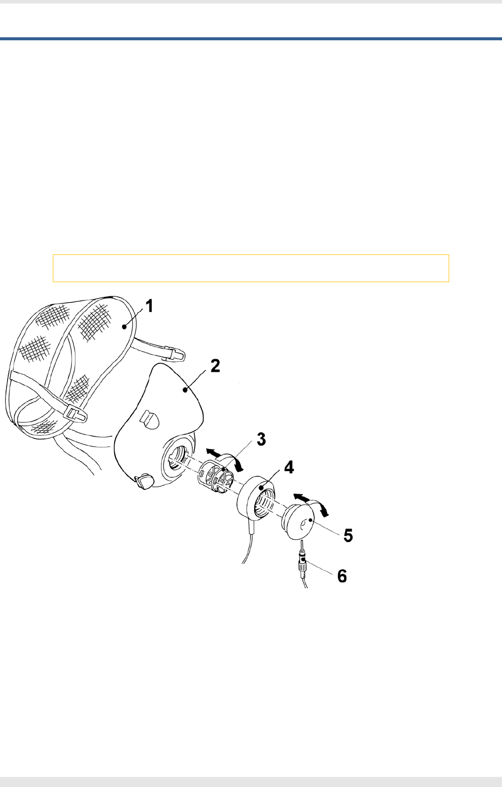
Assemble the mask and the flowmeter
K5 is provided with a turbine flowmeter that can be easily disassembled for allowing cleaning and disinfection.
1. Plug the turbine in the mask adapter by pushing and rotating it clock-wise till you feel a stop.
2. Insert the optoelectronic reader over the turbine and press it till the mask.
3. Plug the wind cover as described in point 1.
4. Plug the sampling tube in the little hole located in the wind cover.
5. Plug the turbine cable in the Flow plug of the K5 unit.
6. Connect the sampling line to the Inlet plug of the K5 unit.
Note: In order to preserve items composing the mask, it's recommended to grease periodically O-rings in the
optoelectronic reader with Silicone compound grease.
1.
Headcap 2.
Mask
3.
Turbine 4.
Optoelectronic reader
5. Wind cover
6. Sampling line
Fixing the K5 to the subject
The following steps are described to fix the unit to the subject or telemetric use. For laboratory use, please consider steps #1, 2 and 4.
1. Fix the heart belt to the patient’s box thorax (see below).
2. Let the subject wear the face mask (see below).
3. Let the subject wear the harness (see below).
4. Place the oximeter (if available and desired) on the subject’s finger.
34 - Installation - Patient’s preparation
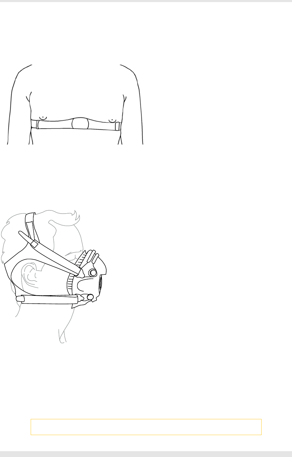
5. Fix the K5 unit to the harness through the screw on the bottom of it.
Fixing HR elastic belt on the subject
To assemble the HR belt:
1. Attach the elastic strap to the HR belt.
2. Adjust the strap to fit tightly and comfortably around the subject’s thorax.
3. Secure the strap tightly around the chest (below the nipple line) and lock the buckle.
4. You may wet the grooved electrode areas with saliva, contact lens solution or an alternative saline solution to help it stick to the subject.
The transmitter should be worn against bare skin to ensure successful operation. If a transmitter is worn over a shirt, the shirt should be wet
underneath the electrode area to achieve proper conductivity.
To acquire the most accurate HR signal you should place the HR probe as close as possible to the HR belt.
Fixing the mask to the subject’s face
Fix the mask as illustrated in the picture below. Adjust the elastic bands on the head cap as necessary to eliminate possible leaks and create a tight
seal around the subject’s face.
Positioning ECG electrodes (if an ecg is used)
Correct electrode placement is important for acquiring a successful ECG signal. Patient preparations that may be performed to improve the signal
include the removal of oils, lotions and hair from the skin.
1. Shave the area in which the electrodes will be placed.
2. Using a slightly abrasive cloth, cut an X where the electrodes will be placed.
3. Rub the area with gauze that has been saturated with either ether or acetone.
4. Remove any residual with dry gauze.
5. Apply the patient cable to the electrodes and place them as shown in the following picture.
Note: The patient cable and the transmitter are not water-proof. You should prevent any liquids from penetrating
the area and avoid submerging the electrodes in liquid.
Installation - Patient’s preparation- 35
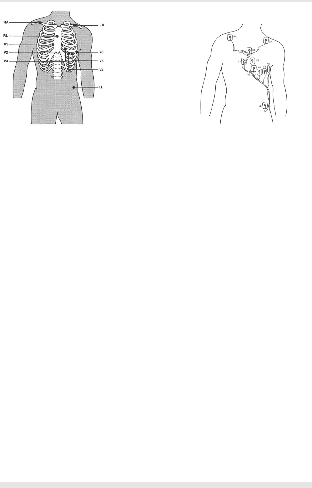
The electrodes should be placed as follows:
V1 4th intercostal space, to the right of the sternum.
V2 4th intercostal space, to the left of the sternum.
V3 Between V2 and V4 electrodes.
V4 5th intercostal space, on the midclavicular line.
V5 5th intercostal space, on the anterior axillary line.
V6 5th intercostal space, on the left midaxillary line.
Limb electrodes for the arms should be placed in the subclavicular areas.
Limb electrodes for the legs should be placed on the trunk at the level of the bottom rib.
Warning: QRS morphology may be slightly different from the standard ECG due to the different positioning of lower
limb electrodes. To reduce these differences attempt to position the LL electrode as low as possible.
36 - Installation - Patient’s preparation

Connecting the K5 to the PC
K5 unit communicates with the PC via Bluetooth or via USB. Both connections can be used for real-time testing (laboratory mode) or for
downloading tests performed in telemetry or holter mode.
For a description of these modes, see the chapter K5 operation.
Note: The USB connection (to PC or any other USB devices) doesn’t charge the battery.
Bluetooth connection
To activate the Bluetooth connection, please enable the Bluetooth communication on the PC and associate the device with the PC.
USB connection
To connect the unit via USB connection, connect the USB cable between the standard USB port on the PC and the connector on the K5 unit.
Installation - Connecting the K5 to the PC- 37

How to contact COSMED
You may contact the manufacturer directly at the following address for information:
COSMED S.r.l.
Via dei Piani di Monte Savello, 37
00041 - Albano Laziale (RM)
ITALY
Voice: +39 (06) 931.5492
Fax: +39 (06) 931.4580
email: customersupport@cosmed.it
Internet: http: //www.cosmed.com
Complaints, feedback and suggestions
If you have any complaints, feedback or suggestions you may inform us at complain@cosmed.it.
38 - Installation - How to contact COSMED
K5 Operation

K5 Operating modes
K5 is a versatile system. You can use it in the field or in the lab without any kind of limitation. Test can be carried out in the following three different
configuration:
• Holter Data Recorder
• Telemetry Data Transmission
• Laboratory Station
Holter Data Recorder
Using the system in the field without the PC, you can store data in the unit. The memory allows to store up to 2 million of breaths, when the test is
completed, the results can be downloaded to the PC via the USB cable or Bluetooth connection.
It is ideal operating modes if you need to test a patient difficult to monitor by Telemetry (i.e. climbing, long distances races, etc). The memory
capacity of the K5 is able to store data up to 2 million of breaths. The system saves data for each breath, hence time storing capacity depends on the
respiratory frequency.
Telemetry Data Transmission
The K5 unit contains a small Bluetooth module that allows to send data by telemetry. All data are transmitted to the PC, that must have the
Bluetooth enabled and must be associated in advance with the K5 unit. On the PC, the researcher can visualise data on line both in table and
graphic format. Anyway, tests are stored in the memory of the portable unit, thus in case of transmission interferences no data are lost. By using
the system with a PC, the software can also control and synchronise ergometers by using user defined exercise protocol.
This mode is useful in case you need to view the test in real time.
Laboratory Station
Although K5 has been designed for tests in the field, it can also be used as a conventional laboratory station as it offers the same features of the
best stand-alone devices. Under this operating mode the K5 Portable Unit is simply connected to the PC through the USB port and all tasks are
performed exactly like any conventional laboratory device. Anyway tests are stored on the memory of the portable unit as well.
You can also drive an ergometer if a second serial port is available in the PC.
40 - K5 Operation - K5 Operating modes

User interface
The user interface is based on a LCD touch screen display and four keys. The display is resistive in order to allow the user to use it also with gloves,
wet fingers, etc.
To select an icon on the screen, please touch it with a finger or with a touch screen pen (not supplied).
To select a function carried out by a key, please press the corresponding key.
The four keys
Start the test recording
Return to the previous menu / Start the auto-check function (see Auto-check section)
Turns the device on or off
Return to the Home menu / Enter a marker during a test
K5 Operation - User interface- 41

Settings
The Settings menu is accessible by pressing the related icon from the Home menu.
International
The International screen allows the user to:
• Set the time zone (Time zone), the current date (Date) and the current time (Time). See below for more information.
• Synchronize the internal clock with the GPS time (Sync with GPS). If deselected, you can change the time according your needs, otherwise
the time will be synchronized with the GPS. The last choice is more precise and it is recommended.
In order to change the time zone, press the arrow near the time zone and select the proper time zone.
In order to change the date, press the arrow near the date and enter the current date. Press OK KEY to confirm or ESC KEY to abort.
The arrow allows to move across the fields, the BACKSPACE key allows to delete the selected text (if a text is selected) or the previous character.
In order to change the time, press the arrow near the time and enter the current time. Press OK KEY to confirm or ESC KEY to abort.
The arrow allows to move across the fields, the BACKSPACE key allows to delete the selected text (if a text is selected) or the previous character.
System
The System screen allows the user to:
• If the wireless (Bluetooth) is enabled (Wireless)
• If the sound is enabled (Sound)
• The time in seconds after which the screen light is reduced (Screen timeout)
• If the GPS is enabled (GPS module)
Note: When the screen light is reduced, a first key pressure (any key can be pressed, both physical or on the display)
restores the full screen functionality, then the next pressure activates the desired function.
IntelliMET (option)
The IntelliMET screen allows the user to:
• Define the sampling mode (Sampling Mode) between Breath by breath (BxB) or Dynamic mixing chamber (Dmc)
• Define the time interval (in minutes) between two subsequent auto-calibrations (Auto cal rate)
• If the ECG measurement is enabled (ECG Measur), for example if an ECG is connected through the connector
• If the SpO2 measurement is enabled (SPO2 Measur), if an oximeter is connected to the device (via Bluetooth)
• If the BTPS correction is enabled (BTPS Enabled)
42 - K5 Operation - Settings

Utility
The Utility menu is accessible by pressing the related icon from the Home menu.
Database
The Database screen allows the user to:
• Search into the database (Search)
• Backup the database on an external SD card (Save DB to SD)
• Erase the database (Erase DB)
• Consult the database status (DB status)
Search into the database
It allows the user to search into the database for a subject, a test date or a test.
Backup the database
It allows the user to save the entire database on the SD card.
Note: A compatible SD card must be present into the K5 unit.
Erase the database
It allows the user to erase all the database.
Press OK to confirm, CANCEL to abort the operation.
Note: All data will be lost and cannot be recovered!
Consult the database status
It allows the user to check the database status (registered subjects, archived tests, database size and uptime)
Control Panel
The Control Panel screen allows the user to check all the electrical signals as well as other equipment functions.
The UP and DOWN arrows allow you to navigate through the different pages of the panel.
Above the data, some keys are shown for:
• Activate/deactivate the sampling pump
• Sample the gas from the sampling line (activated) or from the air inlet (deactivated)
• Let the sampled gas passing through the mixing chamber if activated
• Enable/disable the automatic adjustment of the pump flow rate if the analyzer pressure changes
• Enable/disable the Pwm function in Dynamic mixing chamber mode
• Navigate through the keys
• Show data in mV or in current unit of measurement
• Show data in graphic or tabular format
• Adjust the CO2 zero
• Adjust the CO2 gain
• Adjust the O2 trimmer
Exit with the EXIT icon.
Navigation
The Navigation screen is a control panel that allows the user to view all the GPS-related data (position, time, speed, etc.).
K5 Operation - Utility- 43

The UP and DOWN arrows allow you to navigate through the different pages of the panel.
Above the data, some keys are shown for:
• Enable/disable the GPS
• Delete the last GPS data in cache (for new fixing not starting from a previous position)
• Activate the GPS at 10 Hz (if enabled) or at the standard frequency (if disabled)
• GPS Data
• Show the compass
• Synchronize the device time with the GPS time
Exit with the EXIT icon.
44 - K5 Operation - Utility

Calibration
The Calibration menu is accessible by pressing the related icon from the Home menu.
Regular calibration is necessary to assure your system is acquiring reliable measurements.
Calibration frequency
The table below shows a summary with the calibration intervals recommended by COSMED.
Calibration Recommended interval
Turbine
Each week, if the flowmeter is changed, if the ambient conditions (temperature, humidity and pressure)
change significantly and in all the cases you suspect that the measurements are not reliable anymore
Room air Each day and before each test
Reference gas Each day and before each test
Delay Once a week or when the sampling line is changed
Flowmeter calibration
This function allows the user to calibrate the flowmeter, correcting the errors caused environmental changes that may affect the turbine, repeated
use, obsolescence, etc.
Flow/volume calibration is performed using a 3-liter calibration syringe. If the syringe is not included in the packaging it can be ordered directly
from COSMED, REF C00600-01-11.
Each flowmeter requires a separate calibration.
Note: If an anti-bacterial filter is used during testing, you should also use one when performing the turbine
calibration.
Flows and volumes are measured by the bidirectional digital turbine, which offers a very low resistance to flow. Air passing through the helical
conveyors cause the spiral rotation of the turbine rotor.
The rotating blade interrupts the infrared light beamed by the two diodes of the optoelectronic reader.
The turbine flowmeter does not require daily calibration since it is not affected by pressure, humidity and/or temperature. However, regular
calibration should still be performed as well as the recommended maintenance procedures (see System maintenance).
Perform a turbine calibration
1. Connect the turbine to the optoelectronic reader and this one to the K5 unit
2. Connect the calibration syringe to the turbine
3. Begin with the syringe piston pushed all the way in. When the unit is ready, move the piston in and out for 6 inspiratory and expiratory strokes.
The values will be automatically displayed.
4. At the end of the calibration the inspiratory and expiratory gain are shown
5. Exit with the EXIT icon.
Preface to the analyzers calibration
The system allows three calibrations:
1. Reference gas calibration
2. Air calibration
3. Delay calibration
The Room air calibration, forced by the system before every test, consists of a sampling room air. It updates the baseline of the CO2 analyzer and the
gain of the O2 analyzer, in order to match the readings with the predicted atmospheric values (20.93% for O2 and 0.03% for CO2).
The Reference gas calibration consists of sampling a gas with a known composition (i.e. 16.00% for O2 and 5.00% for CO2) from a calibration
cylinder, and updating the baseline and the gain (span) of the analyzers in order to match the readings with the predicted values (i.e. 16.00% for O2
and 5.00% for CO2).
K5 Operation - Calibration- 45

The Delay calibration, recommended to be carried out once per week or whenever the sampling line is replaced, is necessary to measure accurately
the time necessary for the gas sample to pass through the sampling line before being analyzed.
Note: Cellular phones should be turned off to eliminate potential electrical interferences.
Reference Gas calibration
The software allows to automatically calibrate zero, gain and alignments of the gases sensors. Even if the program doesn't force you to carry out the
calibration, the system should be calibrated before each test. To perform a sensor calibration, a cylinder with a known concentration of mixed gas is
necessary. It is suggested to use CO2 5,00% , O2 16% concentrations and N2 for balance.
Note: After turning on the unit, wait 45 minutes warm up time before starting the calibration procedure.
Notice: Do not use mixtures with a O2 concentration above 24% (out of the O2 sensor range) or under 15%.
Notice: Before calibrating be sure the "Reference values" of room air and reference gas are properly entered.
1. Connect the pressure regulator for calibration to the calibration cylinder (if not connected yet)
Note: The cylinder must be open, but the pressure regulator must be closed
2. Connect the sampling line to the Sampling connector on the K5 unit and leave the other end free at the air
3. After flushing the analyzers, the system start calibrating the CO2 zero and the O2 span
Caution: During this first phase be sure to put the sampling line far from the exhaled gas otherwise calibration could
be affected.
4. When required, connect the free end of the sampling line to the pressure regulator and open the regulator
Note: If a message “Tank gas not detected!” is shown, please check if the cylinder is open and/or it is not empty.
5. At the end of the calibration, exit with the EXIT icon
Room Air calibration
Note: After turning on the unit, wait 45 minutes warm up time before starting the calibration procedure.
Important: During calibration always remove the sampling tube from the optoelectronic reader. Do not remove the
sampling tube from the Portable Unit otherwise calibration could be affected.
Caution: During Room Air calibration be sure to put the sampling line far from the expired gas otherwise calibration
could be affected.
Caution: Room Air calibration performed in small rooms (high concentration of CO2) affects the calibration results
and the accuracy of the following test.
1. Connect the sampling line to the Sampling connector on the K5 unit and leave the other end free at the air
2. After flushing the analyzers, the system start calibrating the CO2 zero and the O2 span
3. At the end of the calibration, exit with the EXIT icon
Delay calibration
The delay calibration procedure is a calibration included in the software due the time alignment between flow and gas concentration
measurements is one of the potential problems to consider to assure accurate readings during test. The gas delay calibration is the measurement of
time required by the gas to reach the gas analyzer.
For "breath by breath" analysis it is essential that the instantaneous flow rate must be multiplied by the proper time-matched expired gas
concentration. Although flow can be instantaneously measured, gas concentration measurements can be calculated with a delay related both to
the time necessary for the gas to be transported to the sensor and to intrinsic characteristics of the analyzer principle.
46 - K5 Operation - Calibration

Two factors contribute to the time alignments delay. K5 uses a capillary sampling tube with a pump to draw a continuous gas sample into the
analyzers. The gas transport time depends on the dimensions of the tube and on the pump flow rate. Additionally the gas sensors have a response
time that must be added to the above delay for calculating the total delay.
The software of the K5 by carrying out the Gas Delay procedure calculates this delay and introduces a correction to realign both flow and gas
measurements.
This procedure must be carried out each time some changes occur in the sampling system, i.e. when the sampling tube is changed. However it is
recommended to carry out this calibration each week in order to prevent wrongs measurements.
1. Connect the turbine to the optoelectronic reader and this one to the K5 unit
2. Start breathing in the turbine at a constant rate. Synchronize the breath (inspiration and exhalation) with the acoustic signal.
3. After some cycles a message will appear confirming the delay calibration.
4. At the end of the calibration, exit with the EXIT icon
K5 Operation - Calibration- 47

Recommendations for exercise testing
Evaluation of the cardiorespiratory function
Exercise creates an increased demand of energy and gas exchange which must be supplied by the cardiovascular and respiratory systems. The
increase in metabolic rate during exercise creates an increase of oxygen in the muscles. The muscles also generate excess CO2 which must be
removed to avoid lactic acid build up.
Precautions
Laboratory
The room in which testing is performed must be large enough to accommodate the necessary equipment and allow access to the patient in case of
an emergency.
A thermometer and a hygrometer should be present in the testing area and monitored regularly. The subject’s heart rate and perceived exertion
may rise with increased temperatures and/or humidity levels greater than 60%, which may lead to variable cardiovascular responses. An adequate
temperature for testing conditions is 22°C, but temperatures as high as 26°C may be acceptable with efficient air ventilation.
Ending the test
The patient should be monitored with an ECG in resting conditions for at least 8 minutes following the test or until he/she returns to pre-exercise
conditions.
Preparing the patient
To receive the most accurate test results it is necessary to communicate with the patient before, during and after the procedure. The patient should
be well informed of the testing details and receive appropriate instructions prior to the test.
Before testing
The physician conducting the procedure must be provided with a written request including a diagnosis (confirmed or suspected), the indication for
the test and the subject’s current medications.
To standardize the test results and to reduce the patient’s anxiety, you should provide him/her with either written or oral information prior to the
test. When scheduling the exam patients should be instructed to avoid smoking, caffeine and eating for three hours prior to the test. He/she should
also be informed to wear comfortable clothing and shoes during the procedure.
Medications which could impair the effort response and reduce the diagnostic accuracy of the exam may need to be stopped prior to testing (i.e.
Beta Blockers or Calcium Antagonists).
A detailed medical history should be acquired from the patient before performing the test. Medications, tobacco use, current activity levels,
nutritional habits and the presence of any abnormal symptoms should be noted.
Patient assent
The patient should be informed that he/she will be subjected to a maximal or submaximal effort along with the risks of the testing procedure.
Ending the test
The test should end when the maximum value of the oxygen consumption has been reached and the patient’s response has been established or
when the subject requests to stop the test.
48 - K5 Operation - Recommendations for exercise testing
Performing a test
Before starting the exercise test, type in the new patient information or choose the desired patient from the list of patients in the database. The
name of the active patient will be displayed on the status bar.
Note: After turning the device on wait at least the warm-up time before beginning calibration or testing procedures.
Test can be performed according to three different modes, as described in K5 operating modes section above. In the following description, the three
modes are indicated with H (holter), T (telemetry) and L (laboratory) in the column Mode below.
Note: In telemetry mode, activate the Bluetooth both on the K5 unit and on the PC (if needed, using the Long Range
optional module).
# Mode Description
1.
H T L Warm-up the K5 unit for at least 45 minutes before calibration or testing
2.
L Connect the K5 to the PC through the USB cable
3.
H T L Calibrate the unit as described in the Calibration chapter (Turbine, gas, air and delay calibration)
4.
H T L Enter a new subject (New Subject) or select a subject from the database (Search Subject)
5.
H T Let the subject to wear the K5 unit (if desired), as described in the Installation chapter
6.
H T L Start the test by pressing the TEST icon
7.
H T L In order to start recording data, press the key on the K5 unit
8.
H T L Test data (time, heart rate, ventilation, oxygen consumption, CO2 production, etc.) are displayed on the K5 screen.
The UP and DOWN arrows allow you to navigate through the different pages of the panel.
9.
H T L In order to stop the test, press the key on the K5 unit or the EXIT icon on the display
Note: In case of tests performed in Telemetry or Laboratory mode, steps # 3, 4, 6, 7 and 9 can be also performed from
the Omnia Software (see the software user manual for further details).
K5 Operation - Performing a test- 49

Download a test on the PC
Tests performed on the K5 can be downloaded on the PC for further analysis and editing.
The download of the test is useful in the following cases:
• if the test is performed in Holter mode, in order to save the test on the PC and to analyze it
• if the test is performed in Telemetry mode, and some interferences occurred during the test. In fact, in this case some breaths could be lost.
Since the unit stores the complete test in its memory, it is possible to download the test to recover all lost data.
To download tests on the PC, please refer to the Omnia Software user manual.
50 - K5 Operation - Download a test on the PC

GPS
The GPS is integrated in the K5 unit. but in the following useful information is reported in order to better understand the GPS functioning and to
obtain the best results.
GPS initialisation
The GPS operates on information gathered from satellites. To gather this information, take your GPS on outside and find large, open area that has a
clear view of the sky (a nearby park would work fine). The GPS needs to receive at least three strong satellite signals to find your location.
At the first power on the GPS needs to be initialized; the initialization is a fundamental procedure for obtaining accurate and reliable data and
should be performed on a large area where the sky is fully "visible".
After the initial self-test is complete, the GPS will begin the process of satellite acquisition and tracking. The acquisition process is fully automatic
and, under normal circumstances, will take approximately 45 seconds to achieve a position fix (15 seconds if ephemeris data is known).
Like all GPS receivers, COSMED GPS utilizes initial data such as last stored position, date and time as well as satellite orbital data to achieve
maximum acquisition performance. If significant inaccuracy exists in the initial data, or if the orbital data is obsolete, it may take up to 5 minutes to
achieve a navigation solution.
The GPS will automatically update satellite orbital data as it operates. The intelligence of the GPS combined with its hardware capability allows
these data to be collected and stored without intervention from the host system.
K5 Operation - GPS- 51
System maintenance

System maintenance
Any service operations not specified in this user manual should be only performed by qualified personnel in accordance with the service handbook.
Rubber mouthpieces, face masks, breathing valves and the other parts are not shipped sterile. These should be disinfected before using according
to the cleaning instructions in this section.
All materials used in the construction of the K5 and its accessories are non-toxic and pose no safety risks to the patient or operator.
The device should be turned off with the power supply disconnected prior to cleaning, disinfecting and/or inspecting the device.
The turbine should be disinfected regularly to ensure the accuracy of measurements.
54 - System maintenance - System maintenance

Cleaning and disinfecting
The goal of infection control is to prevent the transmission of infection to patients/subjects and staff during pulmonary function testing.
Cleaning and disinfecting instructions should be strictly followed to control infections and assure the safety of the patient. Aspiration of residue,
particles and/or contaminated agents could be life threatening.
The recommendations in the following section are retrieved from Miller MR, Crapo R, Hankinson J, et al.: General considerations for lung function
testing. Eur Respir J 2005; 26:153–162.
Prevention of infection transmission
Transmission to technicians
Prevention of infection transmission to technicians exposed to contaminated spirometer surfaces can be accomplished through proper hand
washing and use of barrier devices, such as suitable gloves. To avoid technician exposure and cross-contamination, hands should be washed
immediately after direct handling of mouthpieces, tubing, breathing valves or interior spirometer surfaces. Gloves should be worn when handling
potentially contaminated equipment if the technician has any open cuts or sores on his/her hands. Hands should always be washed between
patients.
Cross-contamination
To avoid cross-contamination, reusable mouthpieces, breathing tubes, valves and manifolds should be disinfected regularly. Mouthpieces, nose
clips and any other equipment that comes into direct contact with mucosal surfaces should be disinfected, or, if disposable, discarded after each
use.
Only the portion of the circuit through which rebreathing occurs must be decontaminated between patients, or, if disposable, discarded after each
use. Disposable sensors, when appropriately used, avoid the need for decontamination of sensors and mouthpieces.
Tuberculosis
In settings where tubercolosis or other diseases that are spread by droplet nuclei are likely to be encountered, proper attention to environmental
engineering controls, such as ventilation, air filtration or ultraviolet decontamination of air, should be used to prevent disease transmission.
Haemoptysis and oral lesions
Special precautions should be taken when testing patients with haemoptysis, open sores on the oral mucosa or bleeding gums. Tubing and
breathing valves should be decontaminated before reuse, and internal spirometer surfaces should be decontaminated with accepted disinfectants
for blood-transmissible agents.
Other known transmissible infectious diseases
Extra precautions should be taken for patients with known transmissible infectious diseases. Possible precautions include the following: 1)
reserving equipment for the sole purpose of testing infected patients; 2) testing such patients at the end of the day to allow time for spirometer
disassembly and disinfection; and 3) testing patients in their own rooms with adequate ventilation and appropriate protection for the technician.
Disposable in-line filters
These may be an effective and less expensive method of preventing equipment contamination.
The use of in-line filters does not eliminate the need for regular cleaning and decontamination of lung function equipment.
Other precautions and warnings
Please take the following precautions during the cleaning and disinfection activities:
1. The responsibility for handling, cleaning and decontaminating reusable medical devices should be assigned to trained, qualified individuals.
2. Appropriate protective clothing (gloves, masks, eye protection, gowns) will minimize the potential for personal exposure to blood borne and
other disease-producing organisms.
3. Immediately separate and contain soiled reusable devices at the point of use and transport to the decontamination area so as to minimize risk
of personal contact with contaminants.
4. A disinfectant solution is only effective if it can contact all surfaces of the items to be disinfected or sterilized.
5. Adequate ventilation is required in the disinfection area to evacuate the chemical vapors from glutaraldehyde (if used). Use lidded containers
for the disinfectant solution when appropriate. The inhalation of fumes from disinfectant solutions or skin contact with liquid disinfectants can
be hazardous to personnel.
System maintenance - Cleaning and disinfecting- 55

Warning: Particular precautions should be taken when testing patients with high risk communicable diseases (i.e.
Tuberculosis, Multidrug Resistant Staphylococcus infections, etc.). When such conditions are present the clinical need
for performing the test should justify the risks.
When performing the disinfection:
• Do not use alcohol or other liquids containing Gluteraldehyde on the exterior surface of the equipment.
• Do not use abrasive powders or glass cleaners containing alcohol or ammonia on the plexiglas component (mixing chamber or canopy) of
the equipment.
• Do not steam autoclave any component other then rubber reusable masks (plastic adapter and clips should be removed).
Warning: Do not immerse any parts in liquid unless indicated (see following sections)
Introduction
Decontamination is a multi-step process that includes preparation at point of use, thorough cleaning and rinsing and a microbicidal process.
Thorough cleaning and rinsing are the first and most important steps in the reprocessing of any reusable medical device. Without thorough
cleaning and rinsing it might not be possible to achieve high level disinfection or sterilization of the device. The purpose of cleaning and rinsing is to
remove all adherent visible soil, to reduce the number of particulates and microorganisms, and to reduce the amount of pyrogenic and antigenic
material. Any organic material, lubricants, or residual cleaning agents remaining on a device can inactivate liquid chemical disinfectants/sterilants
as well as protect microorganisms from destruction.
The second step in decontamination is the microbicidal process which is defined as a process to provide a particular level of microbial lethality (kill).
COSMED components are classified as "semi-critical" items which are devices that come into contact with intact mucous membranes. Semi-critical
devices at a minimum require a high-level disinfection procedure. Sterilization is not absolutely essential.
COSMED components require complete or partial disassembly for cleaning and disinfection. It is the responsibility of the user (health care
personnel) for ensuring that: the cleaning methods recommended can be duplicated in their environment, that appropriate tools, and replacement
parts are available and that instructions are followed correctly.
Cleaning
Note: Please refer to additional, specific cleaning instructions for the turbine assembly below.
Cleaning Agents/supplies
Mild detergents with a neutral pH (7) are recommended for cleaning. Use warm water (22°-43°c) with the mild detergent. To be effective, cleaning
agents must assist in the removal of residual organic soil without damaging the device. cleaning agents should be used in the correct
dilution/concentration and at the correct temperature in accordance with the cleaning agents manufacturer's directions.
Cleaning supplies are very basic, usually consisting of a surgical scrub brush, chenille pipe cleaners, cotton or foam tipped applicators, soft brushes,
and soft cloths. Cleaning supplies should be cleaned and disinfected or sterilized daily.
Water Quality: tap water is acceptable for use in cleaning COSMED components.
COSMED components should be soaked and rinsed in tap water at 22°-43°C to prevent the coagulation of solid substances onto the device and thus
facilitate the removal of debris.
Enzymatic detergents with a neutral pH (7) are recommended when processing difficult-to-clean items with dried-on matter. Soaking mask and
valve components in an enzymatic detergent solution can effectively remove visible debris except for lubricants thus providing an acceptable
alternative to manual cleaning. Rinsing is necessary to remove all traces of detergent and extraneous debris.
Standard cleaning procedure
These steps are common to all the cleaning procedures
Step 1 Preparation at Point of Use. The cleaning of reusable items begins soon after use. At the point of use, personnel wearing gloves and other
protective attire separate disposable items or components from reusable items and discard them in appropriate receptacles. Soil is wiped from
device surfaces with a moist sponge or towel. The soiled/contaminated items are then contained in a manner that will reduce the risk of personal
exposure to pathogens. Items are usually placed in a basket, tray or rigid container for transportation to the processing area, usually transported in
or on a cart, as hand carrying of soiled items is discouraged.
Step 2 Inspection. Inspect the items for damage at all stages of handling. If damage is detected on any of the components it should be identified
and documented. Complete the disinfection/sterilization process and contact technical service for replacement.
Step 3 Presoak. Protective attire is required of personnel handling contaminated items. At the processing area soak or rinse the items in tap water
22°-43° C. Please note that rinse with flowing water is not possible on the turbine. If an enzyme product is required, soak for one to two minutes.
56 - System maintenance - Cleaning and disinfecting

Remove and examine, extend the soak time for components with dried-on matter, prolonged soaking of components may be detrimental, causing
damage to the component surfaces. Refer to the detergent instructions for its usage and soak time.
Step 4 Disassembly. Disassemble the item (if necessary) according to the instructions reported in the corresponding section.
Step 5 Cleaning. Protective attire is required for personnel handling contaminated items. Manual cleaning must be done in a manner that protects
personnel handling the devices from aerosolization and splashing of infectious material.
1. Manual cleaning of the items should be done under 22°-43°C water. Use a neutral pH (7) mild detergent. Water hardness, temperature and the
type of soil affect the effectiveness of the detergents; the detergent manufacturer's instructions should be consulted. Use a small soft brush to
scrub all parts. Abrasive cleaning compounds and implements can damage the items and should not be used. Additional cleaning supplies may
be required to clean stubborn stains or hard-to-reach areas.
2. Items must be thoroughly rinsed with clean water to remove the detergent residuals and debris from the components. Use a flowing triple
rinse cycle at a minimum with tap water. Please note that rinse with flowing water is not possible on the turbine.
3. Dry all components thoroughly using soft clean clothes or disposable paper towels.
Disinfection
The recommendations in this sections have been retrieved from:
William A. Rutala, Ph.D., M.P.H., David J. Weber, M.D., M.P.H., and the Healthcare Infection Control Practices Advisory Committee (HICPAC):
Guideline for Disinfection and Sterilization in Healthcare Facilities, 2008
(http://www.cdc.gov/hicpac/pdf/guidelines/Disinfection_Nov_2008.pdf)
High-level disinfection is the recommended decontamination procedure for semi-critical devices.
Devices are classified semi-critical when they touches mucous membranes or broken skin. Examples of semi-critical devices are flexible endoscopes,
laryngoscopes, endotracheal tubes, respiratory therapy and anesthesia equipment, diaphragm fitting rings, and other similar devices.
Preparing the disinfecting solution
The recommended disinfection solutions are as follows:
• Sodium hypochlorite 0.5% (5000 ppm) prepared fresh for use within 24 hours.
• Sodium hypochlorite 1% (10000 ppm) prepared fresh for use within 30 days.
The first solution can be prepared by adding 1 part household bleach (sodium hypochlorite 5.25%) to 9 parts water. The second solution can be
prepared by adding 1 part household bleach to 4 parts water.
The turbine flowmeter
Guidelines recommend that the turbine should be cleaned and disinfected prior to every test to ensure accurate measurements and to comply with
recommended sanitation measures as follow.
Cleaning the turbine
Follow the standard cleaning procedure reported above, paying attention to the following:
1. For rinsing, do not use flowing water, which may damage the turbine. Rinse the turbine in a vessel, filled of clean water, shaking gently to
remove the disinfectant. Do not place the turbine under running water or move the turbine while submerged.
2. For cleaning and rinsing, do not wet the sampling line.
3. Use the brush (point 1 step 5) only for the external parts of the turbine, in order to avoid damages to the turbine blade.
Disinfecting the ID28 turbine
1. Take out the turbine.
System maintenance - Cleaning and disinfecting- 57

2. Dip it in the disinfectant solution (non-alcoholic based) for about 20 minutes.
3. Rinse the turbine in a vessel, filled of clean water, shaking gently to remove the disinfectant (do not clean the turbine by putting it under
running water!).
4. In order to let it dry, please shake it in air and/or connect it to the calibration syringe and perform some strokes.
5. After cleaning the turbine, check if the turbine propeller rotates freely even with a low speed air flow.
6. Connect the turbine to the reader.
Precautions to take when cleaning, disinfecting and drying the turbine
• Do not expose the turbine to high heat or to a direct flow of water.
• Do not expose the sampling tube or the connector on the end of the cable to any liquids.
• Do not use alcoholic solutions to clean the turbine.
VO2max mask
The face masks, adapters and other components should be cleaned and disinfected prior to every test. Sterilization can optionally be performed on
the rubber mask only. High level disinfection of mask and components ensures patient safety and minimizes the risk of infection.
Disassembling the mask
Remove the round black turbine adapter held within mask and the clips that hold the headcap in place.
Cleaning the mask
Follow the standard cleaning procedure reported above.
Disinfecting the mask
Step 1 Disinfection. Use only liquid glutaraldehyde disinfectant solutions approved as sterilants/disinfectants by the National Authority.
Warnings
The fumes of glutaraldehyde can irritate the mucous membranes of eyes, nose and throat.
Some people develop allergic reactions to glutaraldehyde that can cause skin rashes, headaches and breathing
difficulties.
Containers of glutaraldehyde should be kept closed and in a well ventilated area.
Gloves should be worn made of butyl or nitrile rubber. Do not use latex rubber gloves.
The concentration of glutaraldehyde in the air should not exceed 0.2 ppm.
For emergency, safety or technical information about the glutaraldehyde solution contact the manifacturer.
1. Determine the required soak temperature and time of the sterilant/disinfectant and assure that these requirements are met.
2. Activate the glutaraldehyde solution by mixing the components per the manufacturers instructions. Use the concentration testing devices sold
by the manufacture to determine that the solution is above the minimum effective concentration.
3. Pour the activated glutaraldehyde solution into an appropriate sized basin.
4. Completely immerse the mask and components in the basin. Assure that all channels and cavities are filled with disinfectant and that no air
pockets remain within the components.
5. Cover the disinfectant soaking basin with a tight fitting lid to minimize chemical vapor exposure.
Step 2 Rinsing. Adequate rinsing must follow disinfection to remove all traces of the toxic residues of the disinfectant left on the mask and
components. Sterile water rinse is preferred over tap water. Tap water may contain a variety of micro-organisms which could recontaminate the
components.
1. Rinse 1: Fill a basin with 7-8 liters of water (preferably sterile water). Place the mask and components into the basin and thoroughly rinse all
the components for a minimum of one minute. Empty basin.
2. Rinse 2: Fill a basin with 7-8 liters of water (preferably sterile water). Place the components into the basin and thoroughly rinse all the
components for a minimum of one minute. Empty basin.
Step 3 Hot water pasteurization: an alternative approach for disinfection (it can be performed in place of step 1 and 2). Completely
immerse the device components in a hot water bath. All surfaces should be in direct contact with the hot water for 30 minutes at temperatures set
between 71-76°C.
Step 4 Drying. To prevent the growth of waterborne organisms, the mask and components should be thoroughly dried prior to reassembly and
storage.
58 - System maintenance - Cleaning and disinfecting

1. Dry thoroughly using a soft cloth (preferably sterile) or disposable paper towels.
Step 5 Inspection. All components should be visually inspected for cleanliness, proper function and freedom of defects. Visual inspection provides
evidence of thorough cleaning and proper functioning of all mask and components. Mask assemblies in poor working condition are hazardous to
personnel and patients.
1. Visually inspect all components for cleanliness. If there are signs of residue from the detergent or disinfectant repeat the previous steps. If there
are any signs of remaining stains or organic debris repeat the previous steps. If the cleaning and disinfection steps have been repeated with no
improvement eliminating residual or stains etc, then dispose of the components and replace.
2. Visually inspect all components for defects. Check the rubber parts for tears, nicks, hardening or stiffening, deformation or distortion. Check the
plastic parts for crazing, cracking or stripped threads. Any defective parts should be discarded and replaced.
3. Visually inspect all metal components for corrosion. Replace any metal components showing rust or chipped plated surfaces.
Sterilizing the mask
Sterilization of the silicone rubber face masks can be achieved with steam sterilization.
Warning: Sterilization can be performed on the rubber mask only. Do not apply sterilization on other parts.
Type of Cycle: Gravity Displacement
Type of Load: Wrapped Method
Temperature: 132°-135°c
Cycle Time: 10-15 minutes
Special Notes:
1. Follow cleaning procedures as instructed prior to steam sterilization. Since the degree of sterility assurance depends on the amount of
contamination of items to be sterilized, thorough cleaning procedures are essential.
2. All lubricants should be removed from components because this will interfere with steam contact.
3. Dry devices (components) reduce the potential for wet device packs after sterilization.
4. Sterilization container systems should be cleaned after each use.
Reassembling the mask and components
Reassemble mask and components.
Use appropriate personal protective clothing to assure that you do not recontaminate the components.
Cleaning the headcap assembly
Clean the head cap assembly (with strap clips) by hand washing with a mild detergent. Do not use bleach. Remove the head cap from the mask,
leaving the strap clips attached to the straps. Machine or line dry. Do not iron the head cap assembly.
System maintenance - Cleaning and disinfecting- 59

Sampling line maintenance (Permapure)
• Do not bend, squash or deform the sampling line. Any “kink” in the sample line will reduce the internal lumen of the line and affect
accuracy of measurement.
• Do not keep the sampling line open to the atmosphere, particularly in crowded or smoky environments. Keep the sampling line in sealed
plastic bag in a dark cool and dry place.
• If saliva enters the tube it should be replaced immediately.
• Periodically grease the O-ring on the connector to ease fitting to optical flowmeter.
• Replace the sampling line every 100 exercise tests or 200 PFT test or every 6 months. In any case, sampling line will become discoloured
(brown) with age and may cause calibration to fail.
• Replace the sampling line if the Autocheck failed.
Note: ALWAYS replace sample line as the first step in troubleshooting a failed gas calibration.
60 - System maintenance - Sampling line maintenance (Permapure)

Inspections
The equipment requires inspections to be carried out to assure proper electrical and mechanical safety levels.
The inspections are recommended after extensive use of the equipment or after a long period of storage in unfavourable environmental conditions.
The insulation materials of cables, plugs and any other visible parts should also be inspected. The equipment should be turned off and adapters
should be disconnected from the power supply when inspecting the materials.
The turbine and breathing circuits also need to be inspected.
To inspect the turbine, perform the following procedure:
• Verify, by inspection, that the turbine axis fits correctly and the blade is fastened on the axis (you can lightly shake the turbine to note any
anomalous movement).
• Assure that there are no torn or broken components in the breathing circuits.
System maintenance - Inspections- 61
Appendix

Declaration of conformity
Manufacturer: COSMED S.r.l.
Address: Via dei Piani di Monte Savello 37
00041 Albano Laziale (RM)
ITALY
phone: +39-06-9315492
fax: +39-06-9314580
manufacturer of the following equipment:
K5
declares under his sole responsibility that:
• the above listed equipment comply with the essential requirements of the Annex I of the Medical Device Directive 93/42/EEC;
• are classified in Class IIa;
• their design, manufacturing and final checks are performed according the Cosmed’s Quality System, conform to ISO 9001:2008 and
ISO13485:2003 Norms, certified by KIWA CERMET (certificates nr. 387-A and 387-M);
• are CE marked according to the Medical Device Directive 93/42/EEC and certified by KIWA CERMET (certificate nr. MED 9811).
The equipment conform with the following specifications:
Safety: IEC 60601-1
EMC: IEC 60601-1-2
64 - Appendix - Declaration of conformity

Service - Warranty
Warranty and limitation of liability
COSMED provides a one year limited warranty from the date of the original sale of the product. COSMED products are guaranteed to be free from
defect upon shipment. Liability for products covered by this warranty is limited to the replacement, repair or issuance of a credit for the cost of a
defective product at the discretion of COSMED.
The following conditions must exist for the warranty to apply:
1) COSMED is promptly notified in writing by the buyer upon the discovery of defect.
2) The defective product is returned to COSMED with transportation charges prepaid by the buyer.
3) The defective product is received by COSMED no later than four weeks after the last day of the one year warranty period.
4) COSMED’s examination of the defective product verifies that the defect was not caused by misuse, neglect, improper installation or an
unauthorized repair or alteration.
If the product is manufactured by a third-party, the warranties provided by the third-party manufacturer will be the only ones available for the
buyer. COSMED hereby disclaims any warranties or liabilities arising from defects or damages to and/or caused by products manufactured by a
third-party. The buyer must obtain written authorization from COSMED prior to the repair or alteration of any COSMED products. Failure to obtain a
written authorization will result in a void of the warranty.
The limited warranty shall not be enlarged, diminished or modified by the renderings of technical service from COSMED’s agents or employees
when the product is ordered or following the use of the product(s).
Return goods policy for warranty or non warranty repair
Products shipped to COSMED for repair are subject to the following conditions:
1. Products may only be returned upon receiving a receipt which includes the Service Return Number (SRN) from COSMED S.r.l.
2. The SRN report and packing list should be placed on the outside of the package.
3. Returned goods must be shipped with freight and insurance charges prepaid. Collect shipments will not be accepted.
4. The following list of products is not eligible for return unless proven defective.
- Special order items.
- Expendable products.
- Products held over 30 days after the COSMED invoice date.
- Used products not in the original shipping containers.
- Goods which have been altered or abused in any way.
5. The following parts are not covered by warranty:
- Consumables.
- Fragile glass or plastic parts.
- Rechargeable batteries.
- Damages due to inappropriate use of the device.
Repair Service Policy
Goods returned to seller for non-warranty repair will be subject to conditions 1, 2, 3, 4.
Returned goods requiring customs documents (Pro-forma Invoice and Customs Paper) should comply with the Italian law.
• The shipment must qualify as a temporary export.
• Any goods returned to COSMED without customs papers will not be accepted.
For European Community members:
The Pro-Forma invoice should include the following:
• Number
• Description of the product
• Quantity
• Serial Number
• Value in €
• Number of parcel
Appendix - Service - Warranty- 65

• Gross weight
• Net weight
• Reason for repair
If repairs are needed, you may contact COSMED at the one of the following addresses:
COSMED S.r.l.
Via dei Piani di Monte Savello 37
P.O. Box 3
00041 Pavona di Albano - Rome, Italy
tel. +39 (06) 9315492
fax +39 (06) 9314580
E-mail: customersupport@cosmed.it
USA contact:
COSMED USA Inc
2211 North Elston, Suite 305
Chicago IL 60614 USA
Phone: +1 (773) 645-8113
Fax: +1 (773) 645-8116
email: usa.sales@cosmed.it
To ensure that you receive efficient technical service, please specify the nature of the problem as indicated on the assistance information form.
You should save the original packaging in case the need to ship the unit to a technical assistance centre should arise.
66 - Appendix - Service - Warranty

Privacy Information
Dear Customer,
We would like to inform you that your personal data is gathered and will be used by Cosmed Srl in conformity with the requirements of the Italian
privacy law (Decreto Legislativo 196/2003). We believe it is important for you to acknowledge how your personal data is handled.
Personal data treatment and purposes
We request and process your personal data for the following purposes:
a) To place an order, register a product, request a service, answer a survey, enter a contest, allow communication with us and to supply necessary
authorities with the required information.
b) To define your commercial profile.
c) To use your commercial profile for marketing or advertising purposes.
d) For necessary accounting procedures, such as emailing commercial invoices.
e) To provide information to the selected business partners needed to supply your service.
How your personal data is treated
Your personal data will be stored in an electronic format and protected against destruction, loss, unauthorized access or use not conforming to the
purposes listed above.
Consent
The consent to treat your personal data is optional, but if denied COSMED cannot supply the appropriate services.
Holder of the personal data
Personal data is held by Cosmed Srl, Via dei Piani di Monte Savello 37, Pavona di Albano Laziale (RM).
Customer rights
In accordance with Art.7, you may:
a) Obtain confirmation of the existence and sharing of your personal data.
b) Obtain information on the:
• updating, correction or integration of your data;
• deletion or transformation of your personal data;
c) Deny your consent to treatment of your personal data;
These rights can be exercised by a request in writing to the holder responsible for your personal data.
Appendix - Privacy Information- 67

Disposing of electrical equipment
The device cannot be disposed as unsorted municipal waste. Electronic equipment must be collected separately according to the European Directive
2002/96/EEC. Otherwise it can cause dangerous consequences for the environment and human health.
The crossed-out wheeled bin means that the product must be taken to a separate collection when you wish to dispose of it.
68 - Appendix - Disposing of electrical equipment

Safety and conformity
Safety
IEC 60601-1/EN 60601-1;
The complete classification of the device is as follows:
•Class II type BF
•Protection against water penetration: IP66
•Non sterile device
•Device not suitable in the presence of flammable anaesthetics
•Continuous functioning equipment
EMC
The system meets the Standard IEC 60601-1-2.
Telemetry
ETSI EN 301 489-1, ETSI EN 301 489-3, ETSI EN 301 489-17
ETSI EN 300 328
ETSI EN 300 440-2
EN 62479 (max power <20 mW)
Quality Assurance
UNI EN ISO 9001:2008 (Registration n° 387-A Kiwa Cermet)
UNI EN ISO 13485:2012 (Registration n° 387-M Kiwa Cermet)
Medical Device Directive (CE mark)
MDD 93/42/EEC (Notified Body 0476).
Class IIa
FCC
The K5 complies with the following requirements:
•FCC (Federal Communications Commission) Part 15
Operation is subject to the following two conditions:
(1) This device may not cause harmful interference, and
(2) This device must accept any interference received, including interference that may cause undesired operation.
Changes or modification not expressly approved by the party responsible for compliance could void the user’s authority to operate the equipment.
FCC ID: SN7-COSMED-K5
Note: : This equipment has been tested and found to comply with the limits for a Class B
digital device, pursuant to part 15 of the FCC Rules. These limits are designed to provide
reasonable protection against harmful interference in a residential installation. This
equipment generates, uses and can radiate radio frequency energy and, if not installed
and used in accordance with the instructions, may cause harmful interference to radio
communications. However, there is no guarantee that interference will not occur in a
particular installation. If this equipment does cause harmful interference to radio or
television reception, which can be determined by turning the equipment off and on, the
user is encouraged to try to correct the interference by one or more of the following
measures:
-Reorient or relocate the receiving antenna.
-Increase the separation between the equipment and receiver.
-Connect the equipment into an outlet on a circuit different from that to which
the receiver is connected
-Consult the dealer or an experienced radio/TV technician for help.
Appendix - Safety and conformity- 69

Technical features
Portable Unit
Display LCD: 3,5” TFT LCD Transflective (320x240)
65k colors
high visibility with LED-backlit
resistive touch screen
Keyboard: waterproof, 4 keys
PC Communication: USB, Bluetooth
Power supply: Li-Ion rechargeable batteries (autonomy 4 hours)
External mains AC/DC adapter
Gas measurement: Micro-dynamic mixing chamber (standard)
IntelliMET - Intelligent Dual Metabolic Sampling Technology (Mixing Chamber & Breath by breath) (optional)
Dimensions: 174x111x64 mm,
Weight: 780g (including battery)
CPU: 456 MHz with 128MB RAM
Storage capacity: 512 MB Flash (data storage and OS), up to 2.048.000 breaths
Additional memory: SD-HC Card up to 32GB/Fat32 - internal slot user accessible
Battery charger Unit
Weight: 360g
Dimensions: 58x180x122 mm
Mating connector: 5-blade standard battery connector (2 slots)
Flowmeter
Type: Bidirectional digital turbine Ø 28 mm
Flow Range: 0.08-20 l/sec
Ventilation range: 4-300 l/min
Resolution: 14 ml
Accuracy: ± 2%
Resistance: <0.7 cmH2O s/l @ 14 l/s
Oxygen Sensor (O2)
Type: Galvanic Fuel Cell
Response time: 120 ms
Range: 7-24%
Accuracy: ±0.02%
Resolution: 0.02%
Warm-up time: 5 min
Lifespan: 12 months (user replaceable)
Carbon Dioxide Sensor (CO2)
Type: Digital infrared
Response time: 100 ms
Range: 0-8%
Accuracy: ±0.01%
Resolution: 0.01%
Warm-up time: 10 min
Humidity absorber
Capillary of Nafion (Permapure ®)
Power Supply (mains AC/DC adapter)
Input: 100V-240V ±10%; 50/60Hz, 700 mA
Output: 12V dc, 2.5A
70 - Appendix - Technical features

Power Supply (battery charger)
Input: 100V-240V ±10%; 50/60Hz, 1.4A max
Output: 24V dc, 2.71A
Battery
Type: Li-Ion “smart” battery, with LCD charge status
Voltage: 7.2V
Capacity: 3.1 Ah, 22Wh
Environmental Sensors
Temperature: -40°C to +50°C
Barometer: -600 to +5500m (50 to 110 kPa)
Humidity: 0-100%
Wireless Connectivity
Telemetry (standard): Bluetooth 2.1 + EDR Class II (Range 30-50 m line-of-sight)
Telemetry (optional): Long range Bluetooth 2.1 + EDR Class I (Range up to 900 m line-of-sight)
Wireless Device Interface: Bluetooth 4.0 Low Energy (master/slave) for integration with peripherals (SpO2, ECG, etc.)
ANT+ Module (optional): C7 engine (master/slave) for integrating ANT+ profiles up to 8 channels
Other: MFi compatible
Navigation & Motion Sensors
GPS: 10Hz GPS Differential Integrated (SBAS) - position accuracy 2.5 m, speed accuracy 0.1 m/s
Altimeter: Barometric + GPS offset
Accelerometer: 3-axis ±8 g range, 0.244 mg res
Gyroscope: 3-axis ±2000 °/s range, 0.07 °/s resolution
Magnetometer / Compass: 3-axis ±1000 μT range, 0.1 μT resolution
Appendix - Technical features- 71
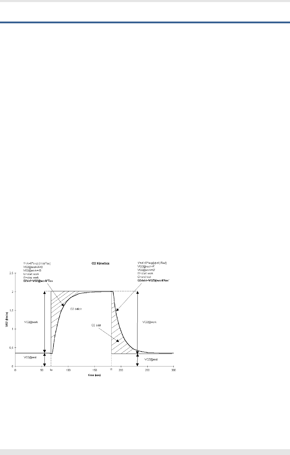
Calculations references
VO2 and VCO2
"Energy Expenditure and Fuel Selection in Biological Systems: The Theory and Practice of Calculations Based on Indirect Calorimetry and Tracer
Methods": M. Elia, G. Livesey, World Rev. Nutr. Diet. Basel, Karger, 1992, vol 70, pp 68-131.
"Nutritional Assessment in Critical Care, A Training Handbook": Donald C. Zavala
Anaerobic Threshold (modified V-Slope)
The intercept of the two slopes is defined as the VO2 above which VCO2 increases faster than VO2 without hyperventilation and can be selected
automatically or manually by the software.
During incremental exercise above the Lactate Threshold, a net increase in lactic acid production results in an accelerated rate in VCO2 relative to
VO2. When plotting these variables against each other a linear relationship is displayed. The slope of the lower component is slightly less than 1.0,
whereas the upper component has a slope greater than 1.0. The intercept of these two slopes is the LT or AT point as measured by gas exchange.
The increase in VCO2 in excess of that derived from aerobic metabolism must be generated from the buffering of lactic acid. This is seen in all
subjects exercising at work levels above their LT.
References
OVS, Original V-Slope method: "A new method for detecting anaerobic threshold by gas exchange", Beaver, Wasserman, Whipp, JAP 1986,
60:2020-2027.
MVS, Modified V-Slope method: "Metabolic acidosis during exercise in patients with chronic obstructive pulmonary disease", Sue, Wasserman,
CHEST 1988, 94:931-938.
Oxygen Kinetics
“Delayed Kinetics of VO2 in the Transition from prior Exercise. Evidence for O2 Transport Limitation of VO2 Kinetics: A Review”; R.L. Hughson and
M.A. Morrissey, Int. J. Sports Med. 4 (1983) 31-39
ISO 8996: Ergonomics – Determination of metabolic heat production, 1990
The following picture displays how O2 debt and O2 deficit values are calculated.
72 - Appendix - Calculations references

References
Gas Exchange
On line computer analysis and breath by breath graphical display of exercise function tests.”; Beaver, Wasserman, Whipp, JAP , 34(1):128-132,
1973
Measurement and analysis of gas exchange during exercise using a programmable calculator”; Sue, Hansen, Blais, Wasserman, JAP, 49(3),
1980:456-461
Principles of exercise testing and interpretation, 2nd edition”; Wasserman et Al, 1994
Clinical Exercise Testing, 3rd edition”, Jones 1988
ERS task force on standardization of clinical exercise testing. “Clinical exercise testing with reference to lung disease: indications, standardization
and interpretation strategies.” J. Roca, B. Whipp, S. Anderson, R. Casaburi, J.E. Cotes, P. Palange…., ERJ 1997; 10: 2662-2689.
Indirect Calorimetry
Energy Expenditure and Fuel Selection in Biological Systems: The Theory and Practice of Calculations Based on Indirect Calorimetry and Tracer
Methods”: M. Elia, G. Livesey, World Rev. Nutr. Diet. Basel, Karger, 1992, vol 70, pp 68-131
Nutritional Assessment in Critical Care, A Training Handbook”: Donald C. Zavala
Sub-maximal exercise testing
Cardiorespiratory Assessment of Apparently Healthy Populations”, Timothy R. McConnell, in ACSM’s Resource Manual for Guidelines for Exercise
Testing and Prescription, 4th Edition, pp. 361-366
Franklin BA, ed. ACSM’s Guidelines for Exercise Testing and Prescription, 6th Edition Philadelphia: Williams&Wilkins, 2000:22-29
Oximeter
National Lung Health Education Program (NLHEP) - Guide to prescribing Home Oxygen. By Thomas L. Petty.
ERJ 2004, 23: 932-646 - ATS/ERS Task force, B. R. Celli, W. MacNee, commitee members - Standard for the diagnosis and treatment of patients with
COPD: A summary of the ATS/ERS position paper.
Appendix - References- 73