COSMED Srl K4B2T-USA TELEMETRY UNIT User Manual I
COSMED Srl TELEMETRY UNIT Users Manual I
Contents
- 1. Users Manual I
- 2. Users Manual II
- 3. Users Manual III
Users Manual I

Cosmed does not assume the liability for interpretation mistakes of this documentation or for casual or
consequential damages in connection with the provision, representation or use of this documentation.
No parts of this manual may be reproduced or transmitted in any form without the express permission of
COSMED Srl.
COSMED Software can be installed only in one device.
Excel is a registered trademark of Microsoft Corporation.
DBIII is a registered trademark of Bordland International Inc.
Lotus 123 is a registered trademark of Lotus Development Corporation .
K4 b2 User manual, XII Edition
01/2005
Copyright © 1998 COSMED
Copyright © 2003 COSMED
COSMED Srl - Italy
http://www.cosmed.it
Part N. C01508-02-91

2 - K4 b2 User Manual
Table of contents
Getting started 13
Important notices ........................................................................... 14
Intended use..............................................................................14
Warnings...................................................................................14
Contraindication ............................................................................. 16
Contraindications for the Spirometer tests................................16
Absolute contraindications.............................................16
Relative contraindications..............................................16
Contraindications for Bronchial provocation tests ...................16
Absolute contraindications.............................................16
Relative contraindications..............................................16
Contraindications for Exercise testing......................................16
Environmental condition of use...................................................... 17
Safety and conformity..................................................................... 18
Safety..............................................................................18
EMC ...............................................................................18
Telemetry .......................................................................18
Quality Assurance ..........................................................18
Medical Device Directive (CE mark).............................18
FCC (only USA version)................................................18
Keynotes ......................................................................................... 19
Typographic keynotes...............................................................19
Graphic keynotes ......................................................................19
System overview ............................................................................. 20
Portable Unit (PU)....................................................................20
Telemetry Data Transmission, Receiver Unit (RU) .................20
Battery Charger Unit (CU) .......................................................20
Flowmeter.................................................................................21
Gas analysers............................................................................21
PC Software..............................................................................21
Before starting................................................................................ 22
Checking the packing contents.................................................22
K4 b2 standard packaging...............................................22
Warranty registration..................................................................... 23
Register the product via software...................................23
How to contact COSMED..............................................23
Complain, feedback and suggestions .............................23
Options/Accessories ....................................................................... 24
Accessories...............................................................................24
Options......................................................................................24
Telemetry data transmission...........................................24
Spirometry Kit................................................................24

Index - 3
PC configuration required...............................................................25
Technical features ...........................................................................26
Portable Unit ..................................................................26
Receiver Unit .................................................................26
Battery charger Unit.......................................................26
Flowmeter ......................................................................26
Oxygen Sensor (O2).......................................................26
Carbon Dioxide Sensor (CO2)........................................26
Humidity absorber..........................................................26
Power Supply .................................................................26
Environmental Sensors...................................................26
Measurements 27
Pulmonary function tests and measured parameters ....................28
Breath by Breath exercise testing.............................................28
Indirect Calorimetry .................................................................28
Lactate Threshold (V-Slope) ....................................................28
O2 Kinetics...............................................................................29
Spirometry Tests (option).........................................................29
FVC - Forced Vital Capacity .........................................29
VC/IVC - Slow Vital Capacity and Ventilatory pattern.29
MVV - Maximum Voluntary Ventilation ......................30
Bronchoprovocation Response.......................................30
Installation 31
Installation sequence......................................................................32
Battery Charger Unit ................................................................32
Check voltage.................................................................32
Turn the Unit on.............................................................32
Charge the batteries........................................................32
Battery low.....................................................................33
Portable Unit.............................................................................33
Warm up.........................................................................34
Warming-up the unit by main power .............................34
Turning on/off the portable unit.....................................34
Connect the rechargeable battery...................................34
Receiver Unit............................................................................35
Turning on/off the receiver unit .....................................35
Receiver unit power supply............................................35
Calibration Gas Cylinder..........................................................35
Connecting the K4 b2 to the patient................................................36
Assemble the mask and the flowmeter.....................................36
Using the "Ultimate Seal".........................................................36
Apply the seal to the mask .............................................37
To remove seal on mask.................................................37
Assembling the flowmeter for spirometry tests........................37

4 - K4 b2 User Manual
Fixing the K4 b2 to the patient..................................................38
Connecting the K4 b2 to the PC....................................................... 39
Connect the Portable Unit to the PC.........................................39
Connect the Receiver Unit to the PC........................................39
Software installation ...................................................................... 40
Installing the software...............................................................40
Run the software.......................................................................40
PC port configuration ...............................................................40
Software main features .................................................................. 41
Display......................................................................................41
Tool bar.....................................................................................41
Show/hide the toolbar.....................................................41
Dialog windows........................................................................41
Use of the keyboard........................................................41
Use of the mouse............................................................41
Scroll bars.................................................................................41
On line help ..............................................................................41
Software version.......................................................................41
Calibration 43
Gas calibration procedures............................................................ 44
Running the Calibration program .............................................44
Log file .....................................................................................44
Setting reference values............................................................44
Set the reference values using the PC software..............44
Set the reference values using the Portable Unit............45
Room air calibration .................................................................45
Room air calibration using the PC software...................45
Room air calibration using the Portable Unit.................45
Reference gas calibration..........................................................45
The calibration unit ........................................................46
Reference gas calibration using the PC software ...........46
Reference gas calibration using the Portable Unit..........46
Gas delay calibration ................................................................47
Delay calibration using the PC software ........................47
Delay calibration using the Portable Unit ......................47
Print the calibration report........................................................48
Edit the calibration factors........................................................48
Turbine calibration......................................................................... 49
Assembling the flowmeter for calibration.....................49
Calibrating the turbine..............................................................49
Turbine calibration using the PC software .....................49
Turbine calibration using the Portable Unit ...................50
Checking the system signals .......................................................... 51
The control panel......................................................................51
Using the control panel...................................................51

Index - 5
Operating modes 53
K4 b2 Operating modes ..................................................................54
Holter Data Recorder................................................................54
Telemetry Data Transmission (option).....................................54
Serial (Laboratory) Station.......................................................54
Portable Unit User Interface diagram............................................55
Holter Data Recorder Mode............................................................56
Operating sequence ..................................................................56
Warming-up the system .................................................56
Enter new patient............................................................56
Calibrate and start the test..............................................56
Stop the test....................................................................57
Transferring test to PC ...................................................57
Telemetry Data Transmission Mode ...............................................58
Operating sequence ..................................................................58
Warming-up the system .................................................58
Connect the receiver unit to the PC................................58
Enable transmission .......................................................58
Enter new patient............................................................58
Enable reception on PC..................................................59
Calibrate and start the test..............................................59
Stop the test....................................................................60
Transferring test to PC ...................................................60
Serial Mode.....................................................................................61
Operating sequence ..................................................................61
Warming-up the system .................................................61
Connect the Portable unit to the PC ...............................61
Calibrate the system.......................................................61
Enter patient data............................................................61
Start the test....................................................................62
Stop the test....................................................................62
Database Management 63
Exercise testing patient's database.................................................64
Enter a new patient ...................................................................64
Find a patient............................................................................64
Edit patient data........................................................................64
Delete a patient.........................................................................64
Uploading tests from the Portable Unit..........................................65
Archive maintenance ......................................................................66
Reorganise the archive .............................................................66
Delete the archive.....................................................................66
Delete a test ..............................................................................66
Backup and restore ...................................................................66
Backup............................................................................66
Restore............................................................................66

6 - K4 b2 User Manual
Spirometry patient's database ....................................................... 67
Patient Card....................................................................67
Visit Card .......................................................................67
Test Card ........................................................................68
Import/export a Tests card........................................................68
Diagnosis Database...................................................................68
Spirometry program settings ......................................................... 69
Graphs ............................................................................69
Serial port .......................................................................69
Units of measurements...................................................69
Using extra fields............................................................69
Customise the fields .......................................................69
Exercise testing 71
Recommendations for the exercise testing .................................... 72
The evaluation of the cardiorespiratory function......................72
Precautions................................................................................72
Laboratory ......................................................................72
Ending the test................................................................72
Preparing the patient.................................................................72
Before testing .................................................................72
Patient assent..................................................................73
Ending the test................................................................73
Real time test.................................................................................. 74
Start a test.......................................................................74
Abort the test without saving data..................................74
End the test saving data..................................................74
View data in real-time ..............................................................74
View graphs in real-time ................................................74
Parameters to view....................................................................74
Manual protocol........................................................................75
Enter Load and Phase.....................................................75
Set the markers...............................................................75
Automatic protocol...................................................................75
Modify the load during the test ......................................75
Set the BPM alarm....................................................................75
Enter the BPM................................................................75
Data management ......................................................................... 76
Viewing data.............................................................................76
View data in table form..................................................76
Creating graphs.........................................................................76
View data in graph form.................................................76
Customise the graphs......................................................77
Switch from graph to data and vice versa ......................77
Viewing predicted values .........................................................78
View predicted values ....................................................78

Index - 7
Anaerobic (Lactate) Threshold detection .................................78
View the Lactate Threshold ...........................................78
Detect the Lactate Threshold..........................................78
Customise graphs for the LT viewing............................78
Fittings......................................................................................79
Fit a graph with a linear regression................................79
Fit a graph with a Mono-exponential regression............79
Calculate the "Mean Value"...........................................80
Oxygen Kinetic.........................................................................80
Run the O2 Kinetic function ..........................................80
Information about the Test .......................................................81
View the Information .....................................................81
Modify the information..................................................81
Summary...................................................................................81
View the summary .........................................................81
Print the data.............................................................................81
Print the current window................................................82
Print the report................................................................82
View the report.........................................................................82
Data Editing ....................................................................................83
Editing values and input numerical values.....................83
Data filtering ..................................................................83
Using the User fields......................................................84
Deleting steps.................................................................84
Advanced Editing...........................................................84
Restore the original test..................................................85
Overwrite the original test..............................................85
Customise the desktop..............................................................85
Customise the display colours........................................85
Smart edit..................................................................................85
Apply the graphical noise suppression...........................85
Apply the threshold noise suppression...........................85
Customise the parameters.........................................................86
Create a new parameter..................................................86
Create a new predicted parameter...................................86
Exporting data..........................................................................87
Export a test....................................................................87
DDE with Excel .............................................................87
Creating Test Protocols ...................................................................88
Create a new protocol.....................................................88
Software configuration ...................................................................89
Data viewing.............................................................................89
Select the parameters to view.........................................89
Select the parameters to view during the test.................89
Sort the parameters.........................................................89
Steady State ..............................................................................89

8 - K4 b2 User Manual
Customise the Steady State detection criteria ................89
Printout reports .............................................................................. 90
Set up the printout ..........................................................90
Select parameters to be printed.......................................90
Customise the printout header........................................90
Electronic reports (*.pdf) ...............................................91
Print the current window ..........................................................91
Print the customised report .......................................................91
Events management during exercise testing ................................. 92
Flow Volume loops...................................................................92
Flow Volume loop during the test..................................92
O2, CO2 vs Time......................................................................92
O2, CO2 vs Time during the test....................................92
O2 Saturation (optional) ...........................................................93
O2 Saturation during the test..........................................93
Spirogram .................................................................................93
Spirogram during the test ...............................................93
View the events after the test....................................................93
Raw data ...................................................................................93
Save Raw data ................................................................94
Resting Metabolic Rate Test 95
Metabolism ..................................................................................... 96
Total Metabolic Rate ................................................................96
Resting Metabolic Rate (RMR)................................................96
Importance to measure RMR....................................................96
Measure of the rest metabolic rate with indirect calorimetry ...96
How to perform a RMR test .....................................................96
Recommendations .......................................................................... 97
Resting metabolic rate test using the face mask .......................97
Resting metabolic rate test using the canopy option.................97
Performing a test using the face mask .......................................... 98
Calibrations...............................................................................98
How to prepare a patient...........................................................98
Start the test ..............................................................................98
Viewing the test........................................................................99
How to modify the average interval .......................................100
Print ........................................................................................100
Performing a test using the canopy option.................................. 102
Calibrations.............................................................................102
How to prepare the canopy and the patient.............................102
Replacement of the power plug....................................102
Connecting the Canopy ................................................102
How to prepare the patient ...........................................103
Performing the test..................................................................103
Viewing the test......................................................................104

Index - 9
How to modify the average interval .......................................104
Print ........................................................................................104
Sub-maximal Exercise Testing 105
Introduction...................................................................................106
Pre-test screening....................................................................106
Sub-maximal exercise testing.......................................................107
Considerations with sub-maximal exercise testing.................107
Staffing...................................................................................108
Test termination......................................................................108
Considerations for accuracy..........................................................109
Performing the test .......................................................................110
An example of testing protocol ..............................................110
Spirometry 111
Setting spirometry options............................................................112
Spirometry..............................................................................112
Automatic Interpretation ..............................................112
Quality control .............................................................112
Parameters manager................................................................113
Predicted values manager .......................................................113
Predicteds set................................................................113
Set the current predicted...............................................114
Formula definition........................................................114
Page set-up..............................................................................115
Spirometry tests ............................................................................116
Forced Vital Capacity (pre)............................................................117
Recommendations ..................................................................117
Perform a FVC (pre) test........................................................117
Test encouragement................................................................117
Perform the FVC test with the encouragement ............118
Slow Vital Capacity........................................................................119
Perform a SVC test.................................................................119
Maximum Voluntary Ventilation...................................................120
Perform a MVV test ...............................................................120
Bronchial Provocation Test ...........................................................121
Bronchodilator test .................................................................121
Methacholine and Histamine Bronchial provocation Tests....121
Perform the test.......................................................................122
Bronchial Provocation protocols Database.............................122
Enter a new Bronchial provocation protocol in the
archive..........................................................................122
Viewing results..............................................................................123
Tests of the current patient...........................................123
Delete a test..................................................................123
Printing results..............................................................................124
Printing Reports......................................................................124

10 - K4 b2 User Manual
Printing the active window.....................................................124
To print the active window...........................................124
Printing a series of reports ......................................................124
Electronic reports (*.pdf)........................................................124
Export data..............................................................................125
Export a test..................................................................125
External devices 127
GPS ............................................................................................... 128
GPS initialisation....................................................................128
Initialize the GPS..........................................................128
Fixing the antenna to the subject.............................................128
Operating sequence.................................................................129
Run a test with GPS......................................................129
Monitoring GPS parameters in real time......................130
Pulse Oximeter (option)................................................................ 131
Operating Sequence................................................................131
System maintenance 133
System maintenance..................................................................... 134
Cleaning and disinfection .......................................................134
Preparing the disinfecting solution...............................134
Cleaning the turbine flowmeter....................................135
Precautions during the cleaning of the turbine.............135
Suggested disinfection solutions ..................................135
Masks cleaning and disinfection.............................................135
Disassembling the different parts of the mask .............135
Cleaning the mask ........................................................135
Disinfecting the mask...................................................136
Permapure maintenance..........................................................136
Inspections..............................................................................136
Replace the fuses ....................................................................136
Appendix 139
Service - Warranty........................................................................ 140
Warranty and limitation of liability ........................................140
Return goods policy for warranty or non warranty repair ......140
Repair Service Policy .............................................................141
Privacy Information ...................................................................... 142
Personal data treatment and purposes.....................................142
How your personal data are treated ........................................142
The consent is optional, but…................................................142
Holder of the treatment...........................................................142
Customer rights.......................................................................142
Converting factors configuration.................................................. 143
Calculations references ................................................................ 144

Index - 11
VO2 and VCO2........................................................................144
Anaerobic threshold (modified V-Slope) ...............................144
O2 kinetics ..............................................................................144
ATS 94 recommendations .............................................................145
ATS recommendations...........................................................145
Predicted values............................................................................146
Automatic diagnosis (algorithm)............................................147
Quality Control Messages ......................................................147
References.....................................................................................149
Gas Exchange References............................................149
Indirect calorimetry......................................................149
Spirometry....................................................................149
Sub-maximal testing.....................................................149

12 - K4 b2 User Manual

Getting started

14 - K4 b2 User Manual
Important notices
Intended use
The measurement of oxygen uptake during sport or real life activities is of great interest
for the development of training programs and the study of their effects on elite athletes
or for assessing the efficacy of a rehabilitation therapy.
A common method for assessing the effects of endurance training is the monitoring of
various respiratory parameters during submaximal exercise.
One difficulty to achieve this goal during sport that cannot be simulated in the
laboratory is to use a reliable and valid portable system to measure VO2 and VCO2 in a
field setting.
Such a portable apparatus may also be useful to determine the energy cost of many sport
and real life activities.
K4 b2 is an electrical medical device designed to perform pulmonary function tests. It is
to be used by physicians or by trained personnel on a physician responsibility.
Caution: Federal law restricts this device to sale by or on the order of a physician.
This equipment has been conceived with the aim of providing an auxiliary instrument
allowing:
• the formulation of lung pathology diagnosis;
• important studies concerning human physiology;
• the collection of important information in sport medicine.
No responsibility attaches COSMED Srl for any accident happened after a wrong use of
the device, such as:
• use by non qualified people;
• non respect of the device intended use;
• non respect of the hereunder reported precautions and instructions.
Warnings
The device, the programme algorithms and the presentation of measured data have been
developed according to the specifications of ATS (American Thoracic Society) and
ERS (European Respiratory Society). Other international references have been followed
when these were not available. All bibliography references are reported in Appendix.
The present handbook has been developed with respect of the European Medical Device
Directive requirements which sort K4 b2 within Class II a.
It is recommended to read carefully the following precautions before putting the device
into operation.
The precautions reported below are of fundamental importance to assure the safety of
all COSMED equipment users.
1. This user manual is to be considered as a part of the medical device and should
always be kept on hand.
2. Safety, measure accuracy and precision can be assured only:
• using the accessories described in the manual or given with the device. Actually
non recommended accessories can affect safety unfavourable. Before using non
recommended accessories it is necessary to get in touch with the manufacturer;
• ordinary equipment maintenance, inspections, disinfection and cleaning are
performed in the way and with the frequency described;
• any modification or fixing is carried out by qualified personnel;
• the environmental conditions and the electrical plants where the device operates
are in compliance with the specifications of the manual and the present regulations
concerning electrical plants. In particular grounding reliability and leakage current
suppression can only be assured when the device three – wire receptacle is
connected to a yellow - green return connected to earth ground. Attempting to
defeat the proper connection of the ground wire is dangerous for users and
equipment.

Chapter 1 - Getting started - 15
3. Before powering the system, check the power cables and the plugs. Damaged
electrical parts must be replaced immediately by authorised personnel.
4. Large gas cylinders, which may be given by the manufacturer or purchased by the
customer, should be secured with cylinder safety chains or safety stands.
5. When removing the protective cap, inspect the cylinder valve for damaged threads,
dirt, oil or grease. Remove any dust or dirt with a clean cloth. If oil or grease is
present on the valve of a cylinder which contains oxygen, do not attempt to use.
Such combustible substances in contact with oxygen are explosive.
6. Be certain that the materials of the pressure regulators are chemically compatible
with the intended gas service before installation. Inspect the regulator for the proper
connection and note the ranges of the pressure gauges. Also examine the physical
condition of the regulator including threads and fittings. Remove any dust or dirt
from the regulator or cylinder valve with a clean cloth. Do not install a regulator on
a cylinder valve containing oxygen if grease or oil is present on either. Such
substances in contact with oxygen are explosive.
7. Cleaning residue, particulates, and other contaminates (including pieces of torn or
broken components) in the breathing circuit pose a safety risk to the patient during
testing procedures. Aspiration of contaminates can potentially be life-threatening.
Use disposable anti-bacterial filters or disinfect each part in contact with the patient
before each test.
8. You must follow all the cleaning procedures in System Maintenance, and you must
thoroughly inspect the components after cleaning and before each patient test.
9. This device is not suitable for use in presence of flammable anaesthetics. It is not
an AP nor an APG device (according to the EN 60 601-1 definitions).
10. Keep the device away from heat and flame source, flammable or inflammable
liquids or gases and explosive atmospheres.
11. In accordance with their intended use K4 b2 is not to be handled together with other
medical devices unless it is clearly declared by the manufacturer itself.
12. It is recommended to use a computer with electromagnetic compatibility CE
marking and with low radiation emission displays.
13. It is necessary to make the PC, connected to the K4 b2, compliant with EN 60601-1
by means of an isolation transformer.
14. Graphical symbols used in accordance to present specifications are described here
below:
Equipment type B (EN60601-1)
Equipment type BF (EN60601-1)
Danger: high temperature
OFF
ON
Protective earth ground
Alternating current

16 - K4 b2 User Manual
Contraindication
The physical strain to execute the respiratory manoeuvre is contraindicated in case of
some symptoms or pathology. The following list is not complete and must be
considered as a piece of mere information.
Contraindications for the Spirometer tests
Absolute contraindications
For FVC, VC and MVV tests:
• Post-operating state from thoracic surgery
For FVC tests:
• Severe instability of the airways (such as a destructive bronchial emphysema)
• Bronchial non-specific marked hypersensitivity
• Serious problems for the gas exchange (total or partial respiratory insufficiency)
Relative contraindications
For FVC tests:
• spontaneous post-pneumothorax state
• arterial-venous aneurysm
• strong arterial hypertension
• pregnancy with complications at the 3rd month.
For MVV test:
• hyperventilation syndrome
Contraindications for Bronchial provocation tests
The bronchial provocation tests must be executed according to the doctor’s discretion.
There are not data that reveal specific contraindication for the bronchial provocation test
through inhalation.
The modern standard processes have been revealing secure in several clinical studies.
However it is recommendable to respect the following contraindications:
Absolute contraindications
• Serious bronchial obstruction (FEV1 in adults)
• Recent myocardium infarct
• Recent vascular-cerebral accident
• Known arterial aneurysm
• Incapacity for understanding the provocation test procedures and its implications.
Relative contraindications
• Bronchial obstruction caused by the respiratory manoeuvre.
• Moderate or serious bronchial obstruction. For ex. FEV1 < 1.51 in men and FEV1
in women < than 1.21.
• Recent infection in the superior air tracts
• During the asthmatic re-acuting
• Hypertension
• Pregnancy
• A pharmacology treatment epilepsy
Contraindications for Exercise testing
Read carefully the exercise testing chapter.

Chapter 1 - Getting started - 17
Environmental condition of use
COSMED units have been conceived for operating in medically utilised rooms without
potential explosion hazards.
The units should not be installed in vicinity of x-ray equipment, motors or transformers
with high installed power rating since electric or magnetic interferences may falsify the
result of measurements or make them impossible. Due to this the vicinity of power lines
is to be avoided as well.
Cosmed equipment are not AP not APG devices (according to EN 60601-1): they are
not suitable for use in presence of flammable anaesthetic mixtures with air, oxygen or
nitrogen protoxide.
If not otherwise stated in the shipping documents, Cosmed equipment have been
conceived for operating under normal environmental temperatures and conditions [IEC
601-1(1988)/EN 60 601-1 (1990)].
• Temperature range 10°C (50°F) and 40°C (104°F).
• Relative humidity range 20% to 80%
• Atmospheric Pressure range 700 to 1060 mBar
• Avoid to use it in presence of noxious fumes or dusty environment and near heat
sources.
• Do not place near heat sources.
• Cardiopulmonary resuscitation emergency equipment accessible.
• Adequate floor space to assure access to the patient during exercise testing.
• Adequate ventilation in the room.

18 - K4 b2 User Manual
Safety and conformity
Safety
IEC 601-1 (1988) /EN 60 601-1 (1990);
Find reported below the complete classification of the device:
• Class I type B device
• Protection against water penetration: IP00, ordinary equipment unprotected against
water penetration
• Non sterile device
• Device not suitable in the presence of flammable anaesthetics;
• Continuous functioning equipment;
EMC
The system meets the EMC Directive 89/336
EN 60601-1-2
EN 55011 Class B (emission), IEC 1000-4-2, IEC 1000-4-3, IEC 1000-4-4
Telemetry
I-ETS 300 220, CEPT T/R 01-04
pr ETS RES 0908 (CE type conformity)
Transmission frequency and output power can be changed upon request according to the
destination country requirements.
Quality Assurance
UNI EN ISO 9001:2000 (Registration n° 387-A Cermet)
Medical Device Directive (CE mark)
MDD 93/42/EEC (Notified Body 0476).
Class IIa
FCC (only USA version)
FCC ID: SN7-K4B2T-USA (transmitter)
FCC ID: SN7-K4B2R-USA (receiver)
This device complies with Part 15 of the FCC Rules. Operation is subject to the
following two conditions: (1) this device may not cause harmful interference, and (2)
this device must accept any interference received, including interference that may cause
undesired operation.
Changes or modifications not expressly approved by the party responsible for
compliance could void the user’s authority to operate the equipment.

Chapter 1 - Getting started - 19
Keynotes
Here are the keynotes used to make the manual easier to read.
Typographic keynotes
These are the typographic keynotes used in the manual.
Style Description
Bold indicates a control or a key to be pressed.
“Italic” indicates a messages shown by the firmware.
Graphic keynotes
These are the graphic keynotes used in the manual.
Illustration Description
shows the button to click in the software to activate the related feature.
20 - K4 b2 User Manual
System overview
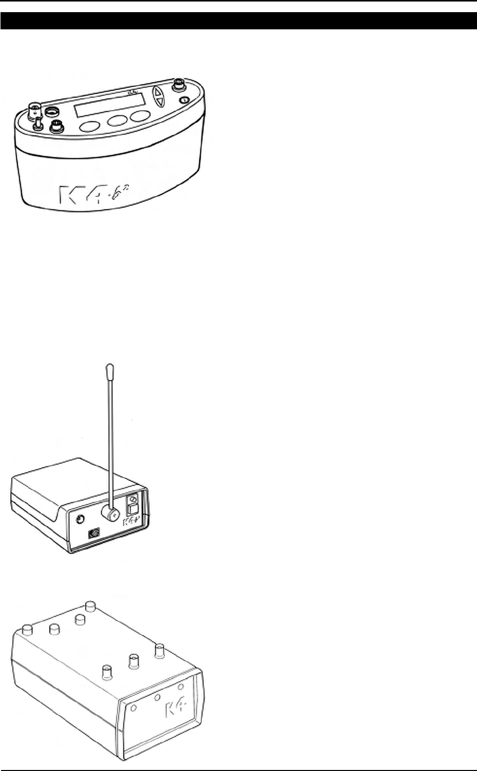
Portable Unit (PU)
It is fixed to the patient during the test by an anatomic
harness. The PU contains the O2 and CO2 analyzers, sampling
pump, UHF transmitter, barometric sensors and electronics. It
is powered by the rechargeable battery fixed to the back side
of the harness.
K4 b² is also provided with a small display, the PU shows in
real time the following parameters: VT, VE, VO2, VCO2, R,
HR, Rf Marker, battery charge level, temperature and
barometric pressure.
USA and Japan versions have the antenna not detachable from
the portable unit.
Besides data processing and presentation, the Portable Unit
has the following functions:
• Patient data input
• Environment data input (humidity)
• Gas and turbine calibration (automatic)
• Memory functions
• Tests data management
• Data loading to a PC (via RS232)
Telemetry Data Transmission, Receiver Unit (RU)
The RU consists of a small unit connected to a PC through the
RS 232 serial port. The transmission is achieved by a
miniaturized transmitter module located inside the Portable
Unit.
Battery Charger Unit (CU)
The CU allows the simultaneously charge of the 3 Ni-Cd
batteries and to supply the PU during the warm up time.

Chapter 1 - Getting started - 21
Flowmeter
The system uses a bi-directional digital turbine. It opposes a very low resistance to flow
(<0,7 cmH2O/l/s to 12 l/s). The air passing through the helical conveyors, takes a spiral
motion which causes the rotation of the turbine rotor. The rolling blade interrupts the
infrared light beamed by the three diodes of the optoelectronic reader. Every
interruption represents 1/6 turn of the rotor, this allows to measure the number of turn in
the time.
Gas analysers
The O
2 and CO2 analysers are temperature-controlled and the internal pressure and
expired flow are monitored for an higher reliability if the measurements.
The K4 b² uses Nafion Permapure ® which is a semipermeable capillary tube capable of
removing the humidity in excess without altering the gas concentrations..
The analysers calibration is automatic and shows both graphically and numerically the
flow and concentration signals and the accuracy of the baseline/gain.
PC Software
The PC software, running on Windows™, allows the user to manage data stored in the
Portable Unit or transmitted to PC. Here following a list of the main features available:
• Test data management.
• Viewing data in table and graphic form
• Automatic and manual detection of anaerobic threshold (modified V-slope
method).
• On-line data presentation during tests.
• Advanced data elaboration (filtering, smoothing, built in spread-sheet features).
• O2 Kinetics (O2 deficit, O2 debt and time constant in both rising and falling edge of
a constant load exercise test).
• Flow-Volume loops during the test and overlapped on the rest FVC.
• Real time display of the O2 and CO2 waveforms during the test.
• Control of any ergometer provided with a RS232 interface.
• Custom fittings (linear and exponential).
• Spirometry (FVC, VC, IVC, MVV).
• File exporting in three different formats (Lotus 123™, Excel™, ASCII).
• Automatic detection of the "Steady State".
• Adding parameters and predicted equations trough the "Formula Editor" tool-kit.
• DDE with Microsoft Excel.
• Customizing software environments (colours, printed parameters...).
• Help on line.

22 - K4 b2 User Manual
Before starting
Before operating the K4 b2 we strongly recommend to check the equipment and register
you as a customer.
Checking the packing contents
Make sure that the package contains the items listed below. In case of missing or
damaged parts, please contact Cosmed technical assistance.
K4 b2 standard packaging
Code Qty Description
(version) a b c d (see note by side)
C00950-01-04 1 K4 b2 Portable Unit
C00952-01-04 1 K4 b2 Portable Unit
C00952-02-04 1 K4 b2 Portable Unit
C00949-01-04 1 K4 b2 Portable Unit
C01599-01-04 1 1 K4 b2 Receiver Unit
C01599-02-04 1 K4 b2 Receiver Unit
C00260-01-04 1 1 1 1 K4 b2 Battery Charger Unit
C01570-01-06 1 Antenna
C00342-01-12 1 Antenna cable
C02120-01-05 2 2 2 2 Turbine Ø 28mm
C02200-01-11 1 1 1 1 Kit optoelectronic reader K4 b2
A 800 900 001 2 2 2 2 Head cap for the adult masks
C02210-01-08 1 1 1 1 Permapure L73cm
C02125-01-10 1 1 1 1 Mask mouth/nose breath adult S
C02135-01-10 1 1 1 1 Mask mouth/nose breath adult M
C02145-01-10 1 1 1 1 Mask mouth/nose breath adult L
A 661 200 001 1 1 1 1 HR elastic belt
A 661 200 002 1 1 1 1 HR polar transmitter
A 182 320 001 2 2 2 2 Anti moisture filter
C01460-01-06 1 1 1 1 RH/TA probe
A 362 060 001 1 1 1 1 Power cord Schuko 2m
C01507-01-12 1 1 1 1 RS232 cable K4 b2
C00659-01-12 1 1 1 1 Cigar light adapter
A 410 110 002 4 4 4 Battery size AA 1,5V
C02100-01-06 3 3 3 Battery pack TX K4 b2
C02100-02-06 3 Battery pack TX K4 b2
C00341-01-12 2 2 1 1 Cable power supply BNCxRF
C01577-01-12 1 1 1 Cable power supply RX unit
C01929-01-08 1 1 1 1 Harness K4 b2 adult
C01143-01-98 1 1 1 1 Velcro strips (set 8 pieces)
C01800-01-05 1 1 1 1 Kit gas calibration
C01509-01-30 1 1 1 1 Carrying case
C01588-01-20 1 1 1 1 Holder Portable Unit
A 680 023 500 2 2 2 2 Time lag fuses 5x20 250V T500mA
A 680 044 500 1 1 1 1 Fuses 6,3x32 250V F5A
C01790-01-36 1 1 1 1 PC software
C01999-02-DC 1 1 1 1 Conformity declaration
C00067-02-94 1 1 1 1 Registration card
C01508-02-91 1 1 1 1 K4 b2 User Manual
sss
Note:
a: Non telemetric version
b: Internat. telemetric version
c: USA telemetric version
d: Japan telemetric version

Chapter 1 - Getting started - 23
Warranty registration
Before using the system, please take a moment to fill in the registration form and the
warranty and return them to COSMED, by doing this you are eligible to the customers
assistance service.
For further information, please refer to the enclosed registration and warranty form. If
the form is not enclosed in the packaging, please contact directly COSMED.
Register the product via software
Together with the PC software, a registration software is supplied. With this software it
is possible to fill in an electronic form with the customer information.
1. To run the software, double click on the icon Registration or select Registration…
from ? menu.
2. Type the requested information and click Send… to send the form via e-mail to
COSMED.
How to contact COSMED
For any information you may need, please contact the manufacturer directly at the
following address:
COSMED S.r.l.
Via dei Piani di Monte Savello, 37
P.O. Box n. 3
00040 - Pavona di Albano
Rome - ITALY
Voice: +39 (06) 931.5492
Fax: +39 (06) 931.4580
email: customersupport@cosmed.it
Internet: http: //www.cosmed.it
Complain, feedback and suggestions
If you have any complain, feedback information or suggestion, please inform us at
complain@cosmed.it.

24 - K4 b2 User Manual
Options/Accessories
Accessories
Code Quantity Description
C02150-01-11 1 Adapter Spirometry kit x opto-reader 2000
C00600-01-11 1 3 liters syringe for flows and volume calibration
C02115-01-10 1 Adult face mask with x Turbine 2000
C01278-01-30 1 Mask mouth/nose breath ID28 paediatric L
C01277-01-30 1 Mask mouth/nose breath ID28 paediatric S
A 800 900 004 1 Paediatric Headcap
Options
Telemetry data transmission
The optional Telemetry data transmission allows the researcher to transmit data on line
to a PC up to a distance of 800 meters. All signals are in real time transmitted via radio
to the RU to be saved and displayed on-line to any PC.
Spirometry Kit
Optional software and accessories designed for performing screening Spirometry such
as Forced Vital Capacity, Slow Vital Capacity, Maximum Voluntary Ventilation and
broncho-challenge tests.

Chapter 1 - Getting started - 25
PC configuration required
• Pentium II 350 MHz.
• Windows 98, XP.
• 64 Mb RAM .
• CD drive.
• VGA, SVGA monitor.
• Serial Port RS 232 available (2 serial ports in case of Ergometer control). An USB
port can replace one RS232 serial port, if using the USB-RS232 adaptor (Cosmed
code A 388 410 001).
• Any Mouse and Printer compatible with the MS Windows™ operative system.
• PC conform to European Directive 89/336 EMC

26 - K4 b2 User Manual
Technical features
Portable Unit
Memory 16,000 breaths
Display LCD 2 lines x 16 characters
Keyboard: waterproof, 6 keys
Serial Port RS 232C
Power supply: Ni-MH rechargeable batteries 3 hours endurance
Thermometer: 0-50°C
Barometer: 53-106 Kpa
Dimensions PU : 170x55x100 mm,
Dimensions battery: 120x20x80 mm
Weight: 400g
Receiver Unit
Transmission range: 800 meters
Battery: 4 x 1.5 V AA
Dimension: 170 x 48 x 90 mm
Weight: 550 g
PC interface: RS 232
Battery charger Unit
Power supply 120V - 240 V
Power consumption 25 W
Flowmeter
Type: Bidirectional digital turbine Ø 28 mm
Flow Range: 0,03-20 L/sec
Accuracy: ± 2%
Resistance: <0.7 cmH2O s/L @ 12 L/s
Ventilation Range: 0-300 litres x min
Oxygen Sensor (O2)
Response time: <150 ms
Range: 7-24% O2
Accuracy: ±0.02% O2
Carbon Dioxide Sensor (CO2)
Response time: <150 ms
Range: 0-8%
Accuracy: ±0.01%
Humidity absorber
Capillary of Nafion (Permapure ®)
Power Supply
Voltage: 100V-240V ±10%; 50/60Hz
Power consumption 60W
Environmental Sensors
Temperature: 0-50°C
Barometer: 400-800 mmHg
Humidity: 0-100%

Measurements

28 - K4 b2 User Manual
Pulmonary function tests and measured parameters
Breath by Breath exercise testing
Symbol UM Parameter
VO2 ml/min Oxygen Uptake
VCO2 ml/min Carbon Dioxide production
Vt l Tidal Volume
FetO2 % End Tidal O2
FetCO2 % End Tidal CO2
R --- Respiratory Quotient
VE l/min Ventilation
HR 1/min Heart Rate
Qt l Cardiac output
AT --- Anaerobic Threshold
VE l/min Ventilation
SV l/min Stroke volume
RF 1/min Respiratory Frequency
FeO2, FeCO2 % Averaged expiratory concentration of O2 e CO
VE/VO2 --- ventilatory equivalent for O2
VE/VCO2 --- ventilatory equivalent for CO2
VO2/HR ml/beat Oxygen pulse
VO2/Kg ml/min/Kg VO2 per Kg
Ti, Te, Ti/Ttot sec time breaths
Vd/Vt --- Vd/Vt ratio
PaCO2 mmHg arterial PCO2 (estimated)
P(a-et)CO2 mmHg Delta PaCO2 – PetCO2
Indirect Calorimetry
Symbol UM Parameter
EE Kcal/day Energy Expenditure
EE/BSA Kcal/day/m2 Energy Expenditure/Body surface area
EE/Kg Kcal/day/Kg Energy Expenditure pro Kg
FAT Kcal/day Fats
CHO Kcal/day Carbohydrate
PRO Kcal/day Protein
FAT% % % Fat
CHO% % % Carbohydrate
PRO% % % Protein
npRQ —- Respiratory quotient not protein
Lactate Threshold (V-Slope)
Symbol UM Description
VO2 @ LT l/m Lactate (Anaerobic) Threshold STPD
R @ LT -- Respiratory Quotient @ LT
Time @ LT hh:mm:ss Time @ LT
VCO2 ml/min CO2 output @ LT STPD
VE l/min Ventilation @ LT BTPS

Chapter 2 - Measurements - 29
HR bpm Heart Rate @ LT
O2 Kinetics
Parameter UM Calculation
O2 deficit l/m VO2@work*tau
O2 debt l/m VO2'@work*tau
Spirometry Tests (option)
FVC - Forced Vital Capacity
Symbol UM Parameter
FVC l Forced Expiratory Vital Capacity
FEV1 l Forced Expiratory Volume in 1 sec
FEV1/FVC% % FEV1 as a percentage of FVC
PEF l/sec Peak Expiratory Flow
FEV0.5 l Forced Expiratory Volume in 0.5 sec
FEV6 l Forced Expiratory Volume in 6 sec
FEV1/FEV6 % FEV1 as a percentage of FEV6
FEV6/FVC% % FEV6 as a percentage of FVC
Best FVC l Best Forced Expiratory Vital Capacity
Best FEV1 l Best Forced Expiratory Volume in 1 sec
Best PEF l/sec Best Peak Expiratory Flow
Vmax25% l/sec Expiratory Flow when 75% of the FVC remains to be exhaled
Vmax50% l/sec Expiratory Flow when 50% of the FVC remains to be exhaled
Vmax75% l/sec Expiratory Flow when 25% of the FVC remains to be exhaled
FEF25-75% l/sec Mid-exp flow between 25-75%FVC
FET100% sec Forced expiratory time
FEV2 l Forced Expiratory Volume in 2 sec
FEV3 l Forced Expiratory Volume in 3 sec
FEV2/FVC% % FEV2 as a percentage of FVC
FEV3/FVC% % FEV3 as a percentage of FVC
FEV1/VC% % Tiffenau index
FEF50-75% l/sec Mid-exp flow between 50-75%FVC
FEF75-85% l/sec Mid-exp flow between 75-85%FVC
FEF0.2-1.2% l/sec Mid-exp flow between 0.2 l - 1.2 l
FiVC L Inspiratory Forced Vital Capacity
FiF25-75% l/sec Forced mid-inspiratory flow
FiV1 l/sec Forced Inspiratory Volume in 1 sec
PIF l/sec Peak Inspiratory Flow
VEXT ml Extrapolated Volume (back extrapolation)
PEFT msec Time to PEF (10% - 90%)
VC/IVC - Slow Vital Capacity and Ventilatory pattern
Symbol UM Parameter
EVC l Expiratory Vital Capacity
IVC l Inspiratory Vital Capacity
ERV l Expiratory Reserve Volume
IRV l Inspiratory Reserve Volume
IC l Inspiratory Capacity

30 - K4 b2 User Manual
VE l/min Expiratory Minute Ventilation
Vt l Tidal Volume
Rf 1/min Respiratory Frequency
Ti sec Duration of Inspiration
Te sec Duration of Expiration
Ttot sec Duration of Total breathing cycle
Ti/Ttot —- Ti/Ttot ratio
Vt/ti l/sec Vt/ti ratio
MVV - Maximum Voluntary Ventilation
Symbol UM Parameter
MVV l/min Maximum Voluntary Ventilation
MVt l Tidal Volume (during MVV)
MRf 1/min Maximum Respiratory frequency
MVVt sec MVV duration time
Bronchoprovocation Response
Symbol UM Parameter
FallFEV1 % Fall in FEV1 from baseline or post diluent
FallVmax50% % Fall in Vmax50% from baseline or post diluent
P10 —- Provocative dose causing FEV1 to fall 10% from baseline
P15 —- Provocative dose causing FEV1 to fall 15% from baseline
P20 —- Provocative dose causing FEV1 to fall 20% from baseline

Installation
32 - K4 b2 User Manual
Installation sequence
Before starting operating with the system make sure to meet the environmental and
operational conditions reported in Chapter 1.
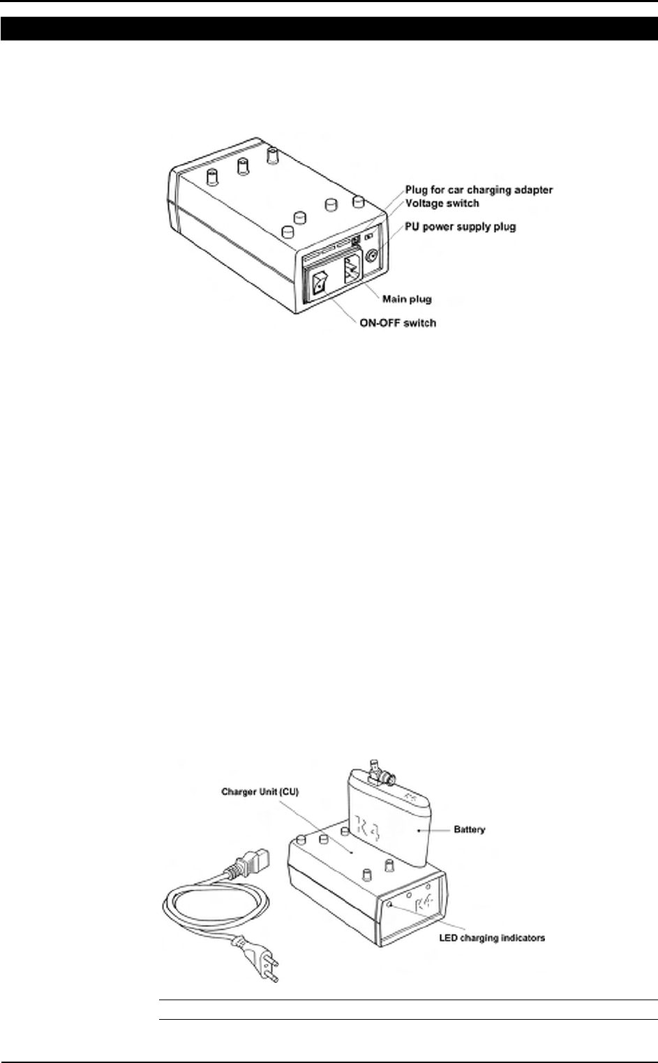
Battery Charger Unit
The Battery Charger Unit allows the following functions:
• Charge 3 rechargeable batteries simultaneously.
• Charge batteries by means of the car lighter plug.
• Supply the K4 b2 Portable Unit directly by the main power.
Check voltage
The Battery Charger Unit is provided with a switch that allows to change the voltage
according to the following values:
• 115V 50-60 Hz (100V-120V)
• 220V 50-60 Hz (200V-240V)
To change setting, move the switch on the new voltage by using a small screwdriver or
a pen.
Turn the Unit on
1. Connect the Charger Unit to the main plug.
2. Turn on the Unit by pressing the orange power switch.
Charge the batteries
1. Insert the batteries into the places on the top of the unit as shown in the illustration
below.
2. The small green LED placed on the front panel warns the charge in progress. The
battery is charged when the light signal placed on the front panel of the Charger
Unit starts blinking.
Note: USA and Japan versions have not the antenna connector on the battery.
sss
Warning: Before turning the
Battery Charger Unit on, check
the voltage switch selected
meets your main voltage.
Chapter 3 - Installation - 33
Battery low
It is recommended to charge batteries before each test. When the batteries are low the
warning message is prompted on the PU by two beeps for an half charged battery and
three beeps for a complete discharged battery.
As soon as the message appears, you must change batteries immediately since the
system has only few minutes of endurance still available. The system allows to change
the battery during testing as well.
During the test, it is possible to monitor the battery status in real time by selecting
Information from View menu.
Portable Unit
The PU can be supplied either by the Charger Unit or by rechargeable batteries. It is
recommended during Warm-up to supply it exclusively by the Charger Unit time in
order to save the battery used normally during the test.
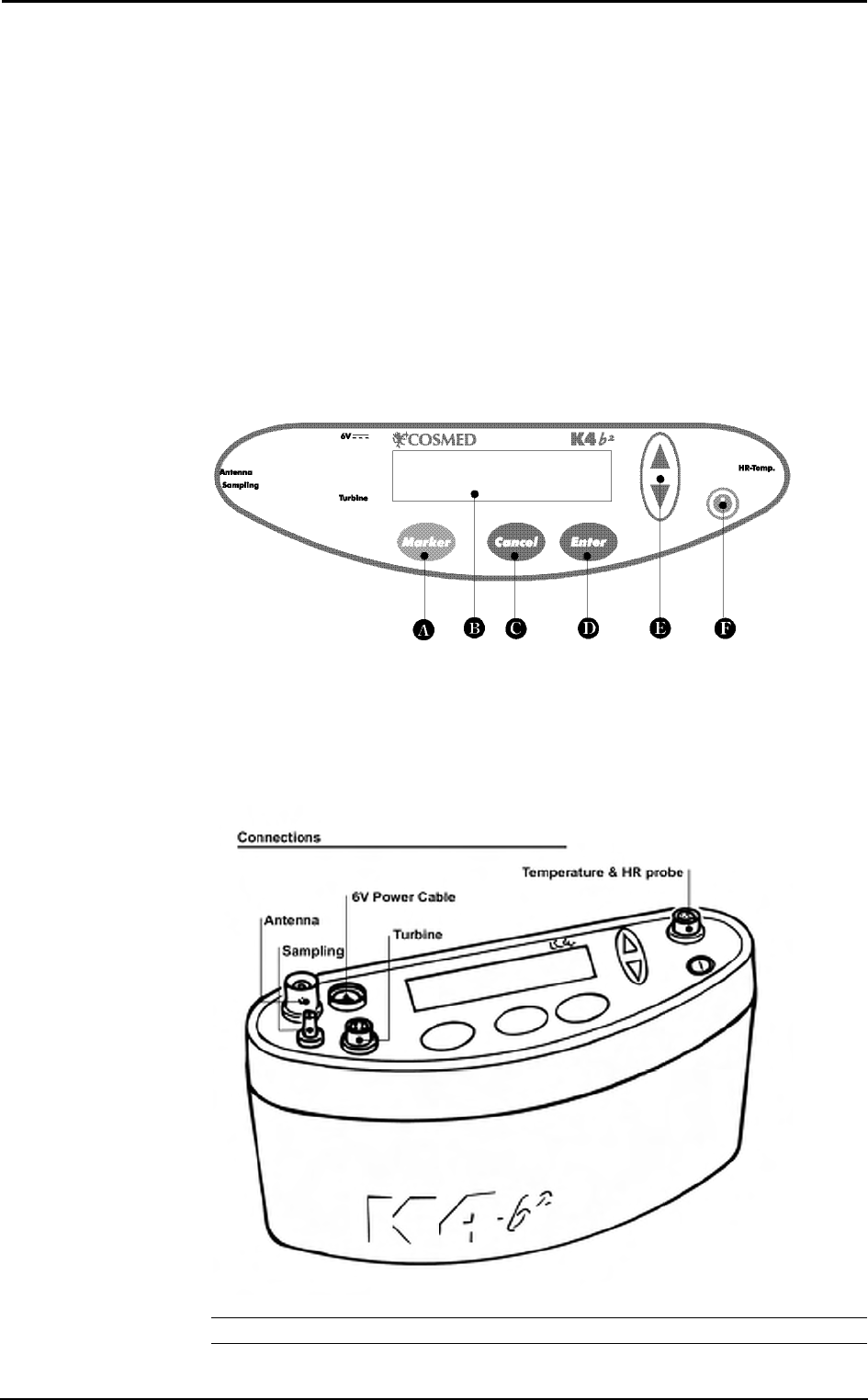
The control panel of the Portable Unit is mainly composed by a keyboard, and 4 plugs
for power supply, turbine, antenna, heart frequency and sampling tube connections. The
following illustrations show in detail the control panel.
A Marker key
B Display
C Cancel key
D Enter key
E Scroll up/down key
F On/Off switch
Note: USA and Japan versions have the antenna not detachable from the portable unit.
34 - K4 b2 User Manual
Warm up
The K4 b2 uses O2 and CO2 heated sensors. We strongly recommend at least 45 minutes
warm-up time at an ambient temperature of 20°C. More time is necessary if the
environmental temperature is lower. Calibration or testing before warm-up time is
completed, can cause wrong results.
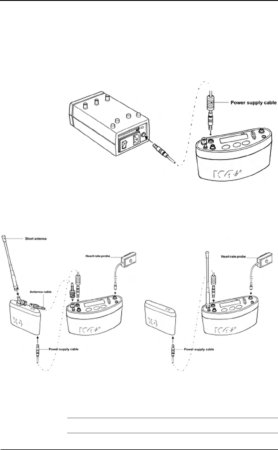
Warming-up the unit by main power
1. Connect the Charger Unit to the main power by the AC power cable.
2. Connect the power-supply cable both in the Charger Unit and K4 b
2 as shown
below and turn both the units on.
Turning on/off the portable unit
To turn the K4 b2 on or off press the on/off key.
Connect the rechargeable battery
Plug the power supply cable into the battery socket as shown in the following
illustration.
International telemetric version USA and Japan Telemetric version
Sometimes you might need to change the battery during the test. To do this you must
change the battery in the shorter time possible. The Portable Unit does not transmit data
while it is not powered.
Warning: During testing make sure to change the battery as fast as possible, since a
long time could compromise the reliability of measurements.
sss
Important: In order to ensure
accurate gas measurements,
you must wait for a warming-
up
time before operating the K4
b². During this period the PU
must be turned on for at least
45 minutes.
sss
Warning: Supply K4 b2 with
Charger Unit for warming up
only.
Chapter 3 - Installation - 35
Receiver Unit
Optionally the K4 b2 is provided with a transmitter board (located inside the K4 b2 unit)
and a Receiver Unit to monitor "on-line" exercise tests performed either in the field or
in the lab. All data measured by the K4 b
2 are transmitted "breath by breath" to the
Receiver Unit in real time. The RU (illustrated below) must be connected to a Personal
Computer with any RS 232 serial port to display data "on-line" in the management
software. The transmission range is 800 meters in open field. However during
transmission the test is stored in the memory of the K4 b
2 Unit so that, in case of
transmission interference no data is lost.
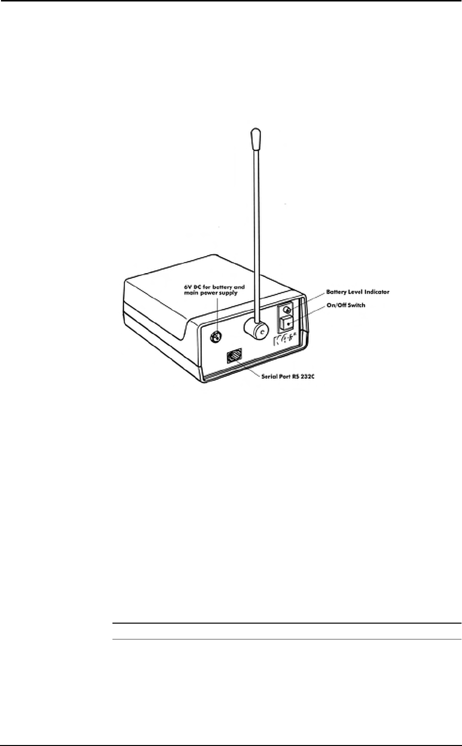
Turning on/off the receiver unit
To turn the receiver unit on or off use the switch on the front side of the unit.
Receiver unit power supply
The K4 b2 Receiver Unit is provided with four 1.5 V AA batteries. Before turning the
unit on be sure that batteries are charged. If the status battery indicator blinks red you
must replace the 4 batteries. The unit can be also supplied by 6V DC power through the
cable provided in the equipment.
The receiver unit can be supplied by two different sources:
• by the Battery Charger Unit: connect the units by the 6V DC cable.
• by 4 AA 1,5V batteries.
Calibration Gas Cylinder
In order to calibrate the sensors you need to have available calibration cylinder with the
following gas concentration:
Cylinder Recommended Gas mixture
Calibration O2 16%, CO2 5%, N2 Balance
For the calibration procedure, see the Calibration chapter.
36 - K4 b2 User Manual
Connecting the K4 b2 to the patient
K4 b2 is a portable system with a total weight lower than 1 kg. Cosmed has developed a
special harness to fix the unit to any subject. The harness consists of a belt that can be
adjusted to fit different sizes and positions. I.e. if you need to test cyclist or rower
athletes we recommend to locate both units (K4 b
2 and battery) on the back of the
subject to increase comfort and to avoid any obstacles during movements. For this
reasons plates are provided with the harness and they can be easily removed and placed
in different positions.
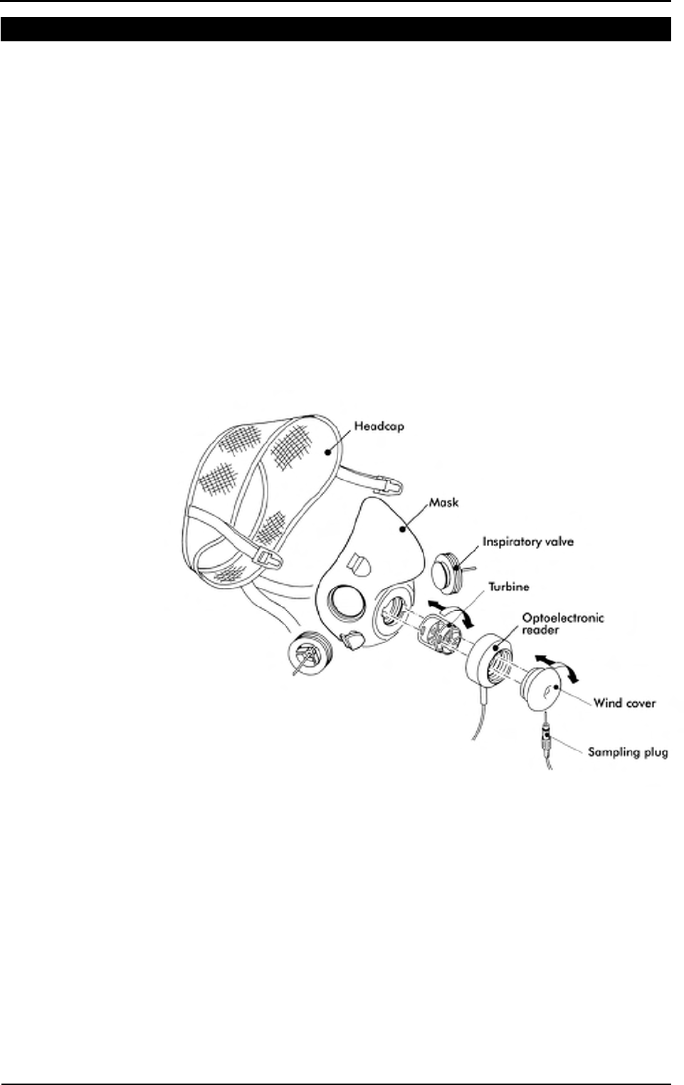
Assemble the mask and the flowmeter
K4 b² is provided with a turbine flowmeter that can be easily disassembled for allowing
cleaning and disinfection.
1. Plug the turbine in the mask adapter by pushing and rotating it clock-wise till you
feel a stop.
2. Insert the optoelectronic reader over the turbine and press it till the mask.
3. Plug the wind cover as described in point 1.
4. Plug the sampling tube in the little hole located in the optoelectronic-electronic
reader.
5. Plug the turbine cable in the Turbine plug control panel of the K4 b2.
Using the "Ultimate Seal"
The "ultimate seal" is a moulded of Elasto-Gel, a glycerine based hydrogel. This
product is a unique polymer gel that forms an intimate seal between the face and the
mask. It has to be used for mask applications on hard to seal faces and where leaks are
not tolerated.
• Will not irritate the skin
• Contains no adhesives.
• Has no odour
• Will not dry out
• Single patient use
sss
Notice: In order to preserve
items composing the mask, it's
recommended to grease
periodically O-rings in the
optoelectronic reader with
Silicone compound grease.
Chapter 3 - Installation - 37
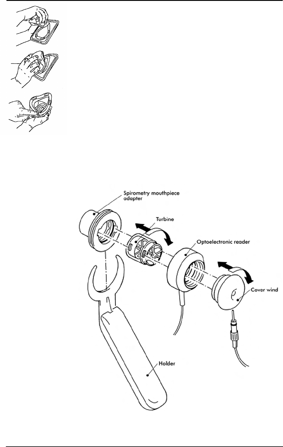
Apply the seal to the mask
Apply seal to clean, residue-free mask only and follow the instructions below:
1. Remove the plastic tray from the bag. Peel off clear film and retain for later use.
2. While holding tray align the nose area of mask to nose area of Ultimate Seal™ gel.
Press together and roll mask down over the surface of the gel seal attaching it to the
mask and releasing it from the tray.
3. If needed, adjust the position of the seal, aligning it with the outer perimeter of the
mask sealing surface.
4. The mask is now ready to be placed on the subject's face.
To remove seal on mask
• The Ultimate Seal™ have been conceived for a single patient use only, it can not be
cleaned or sterilised.
• If mask requires cleaning for a new patient application then pull off and dispose of
the Ultimate Seal™.
• To keep the seal clean between use, keep it attached to the mask and place the clear
film against the Ultimate Seal™ gel on the mask. When the seal becomes
discoloured or opaque (approximately two weeks) dispose of the current seal and
replace it with a new one.
Assembling the flowmeter for spirometry tests
In case the spirometry kit option is purchased assemble the turbine as shown in the
illustration below.
sss
Notice: Avoid the exposure
to the sun. Do not put the
seal into the water.
38 - K4 b2 User Manual
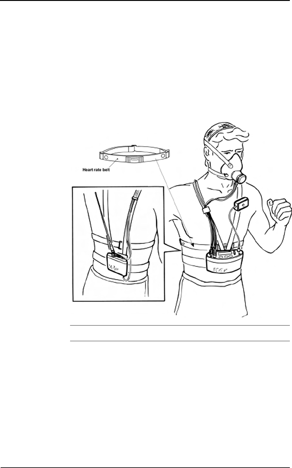
Fixing the K4 b2 to the patient
1. Fix the heart belt to the patient’s box thorax.
2. Fix the K4 b2 unit to the front of the harness. Do the same operation with the battery
on the back .
3. Connect the battery cable to the 6V plug of the K4 b2 control panel. Be sure that the
red plug, that repairs the plug from water or sweat drops, is on the Portable Unit
side.
4. Connect the antenna cable to the Antenna plug of Portable Unit control panel.
5. Insert the heart frequency receiver and temperature probe cable in the HR-Temp
plug placed on the control panel.
6. Insert the male connector of the turbine in the Turbine plug on the control panel.
7. Fix the power supply cables, antenna and turbine on the right side of the jacket with
the velcro stripes provided in the equipment. Fix the heart frequency probe on the
left side.
Note: USA and Japan versions differ from the picture because of the antenna
placement.
sss
Notice: Be sure to fix the
Heart rate probe on the left
side, while the other cables
have to be fixed on the right
side. This must be done for
avoiding interferences
between cables.
sss
Notice: Fix all cables with
the velcro strips provided
with the equipment.
Chapter 3 - Installation - 39
Connecting the K4 b2 to the PC
K4 b2 can be connected to any PC provided with serial port in order to monitor "on-
line" physiological data during any kind of activity.
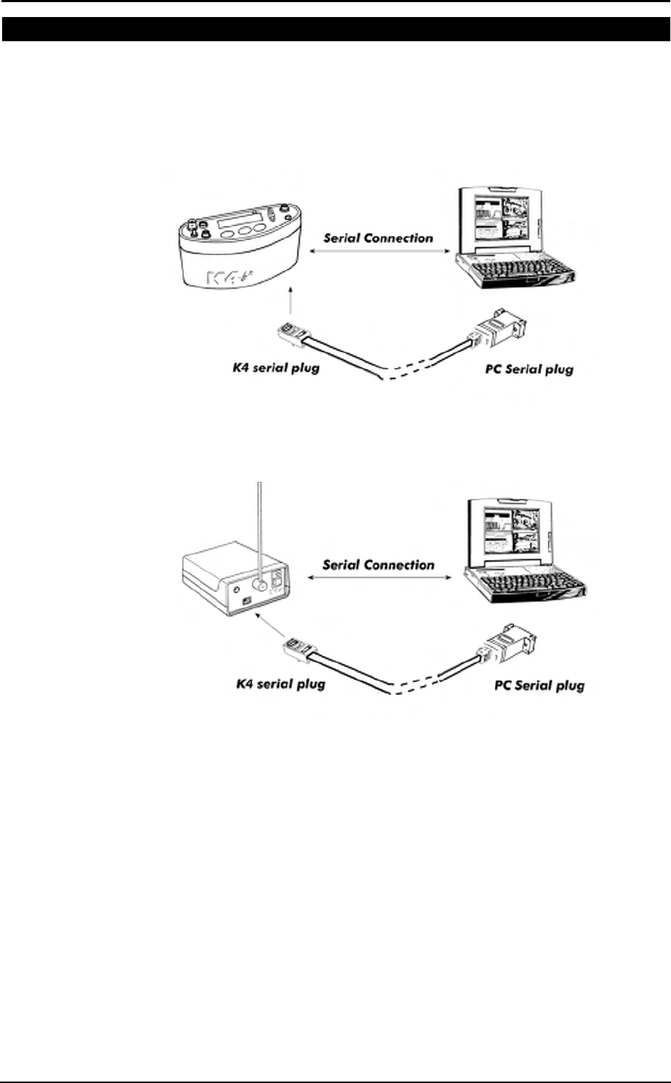
Connect the Portable Unit to the PC
Connect the K4 b2 Portable Unit to a serial port available in the PC. Be sure to set the
K4 b2 software to the proper serial port for the transmission.
Connect the Receiver Unit to the PC
Connect the telemetry module to a serial port available in the PC. Be sure to set the K4
b2 software to the proper serial port for the transmission.

40 - K4 b2 User Manual
Software installation
The software is made of two programs: one for the ergometry and the other one for the
spirometry (option). The two programs share the same archive and use the same
program for the system calibration, even if they are used for performing completely
different tests.
Installing the software
1. Select Run... from Windows Start menu.
2. Insert the disk in the proper drive.
3. In the Command line, type <name of the drive>:\install.
4. Click on OK (or press ENTER key).
5. The program will load up a dialog box and ask for a directory where to be installed.
6. When the installation is over, the program will advise you with a message
indicating that the installation has been successfully completed, click on End.
Note: the directory for the Spiro software must be the same of the K4 b2 (ergo).
Run the software
1. In the Windows Start menu, open the Program Group in which the software was
installed.
2. Click the K4 b2 icon.
PC port configuration
The first time the software is used, it is necessary to configure the communication port
with the PC (USB, COM1, COM2,…).
For further details, see the chapter Database management.
sss
Notice: The software is
copy-protected. Install the
software from the original
disk.

Chapter 3 - Installation - 41
Software main features
Display
The program may contain several windows. The active window is highlighted with a
different colour of the caption. Some functions of the program are "active window"
sensitive (Print, right key of the mouse).
Tool bar
Many of the functions that may be selected from the menu can be activated more
rapidly by clicking with the mouse on the corresponding icon in the tool bar.
Positioning the mouse cursor on one of the buttons of the toolbar (if the option Hints is
enabled), the description of the corresponding function is shown in a label.
Show/hide the toolbar
Select Toolbar from Options menu in order to show or hide the toolbar.
Dialog windows
The typical operating environment of Microsoft Windows is the Dialog box. This
window is provided with a series of fields in which input the information.
Use of the keyboard
• To move the cursor among fields, press the Tab key until you reach the desired
field.
• Press the Enter key to confirm the information input on the dialog box or press the
Esc key to cancel changes.
Use of the mouse
• To move the cursor among fields, move the mouse on the desired field and left-
click.
• Click on the OK button with the Left button of the mouse to confirm the
information input on the dialog box or click on Cancel button to cancel changes.
Scroll bars
Some windows are provided with scroll bars that help to see data exceeding the window
space available.
• To move the scroll bar row by row click the scroll arrows at the end of the scroll
bars
• To move the scroll bar page by page click on the grey area at both sides of the
scroll fields
On line help
COSMED K4 b2 Help is a complete on-line reference tool that you can use at any time.
Help is especially useful when you need information quickly or when the user manual is
not available. Help contains a description of each command and dialog box, and
explains many procedures for accomplishing common tasks.
To get the Help on line, press the F1 key.
Software version
To know the software version and the serial number of the software, select About…
from ? menu.

42 - K4 b2 User Manual

Calibration
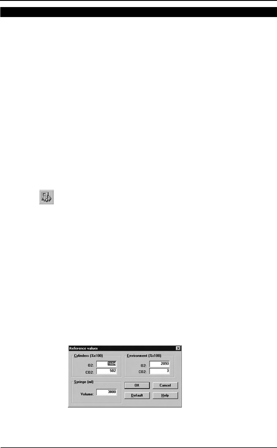
44 - K4 b2 User Manual
Gas calibration procedures
The system can be calibrated according to the following procedures:
1. Room air calibration
2. Reference gas calibration
3. Delay calibration
4. Turbine calibration
The Room air calibration, forced by the system before every test, consists of a sampling
room air. It updates the baseline of the CO2 analyzer and the gain of the O2 analyzer, in
order to match the readings with the predicted athmospheric values (20.93% for O2 and
0.03% for CO2).
The Reference gas calibration, recommended to be carried out daily, consists of
sampling a gas with a known composition (i.e. 16.00% for O2 and 5.00% for CO2) from
a calibration cylinder, and updating the baseline and the gain (span) of the analyzers in
order to match the readings with the predicted values (i.e. 16.00% for O2 and 5.00% for
CO2).
The Delay calibration, recommended to be carried out ones a week or whenever the
sampling line is replaced, is necessary to measure accurately the time necessary for the
gas sample to pass through the sampling line before being analyzed.
The Turbine calibration, recommended to be carried out quarterly, consists in measuring
the volume of a 3 litres calibration syringe and in updating the gain of the flowmeter in
order to match the predicted value.
Running the Calibration program
Start the program and choose Calibration from the Test Menu. The software runs the
Calibration software and the main menu changes accordingly.
Log file
The program creates and updates as default the calibration log file, containing the
conditions and the results of all the calibrations performed by the user.
To access the file select File/Report File... from the calibration program.
Setting reference values
Before starting calibrating make sure that the system has been configured correctly by
setting the right values of gas concentration of: room air (i.e. 20.95% O2 and 0.03%
CO2), of gas mixture contained in the cylinders and the volume of the calibration
syringe (i.e. 3 litres).
Set the reference values using the PC software
This operation must be performed only the first time. The next times, the system keeps
stored the reference values entered in this step.
1. Select Reference Values from the Calibration menu.
2. Type the correct values for the O2 and CO2 room air concentration (i.e. 2093 for
20.93%), and do the same for the gas concentration of the calibration cylinder.
3. Type the volume of the calibration syringe (i.e. 3000 for a 3 litres calibration
syringe).
4. Press OK button to confirm changes.
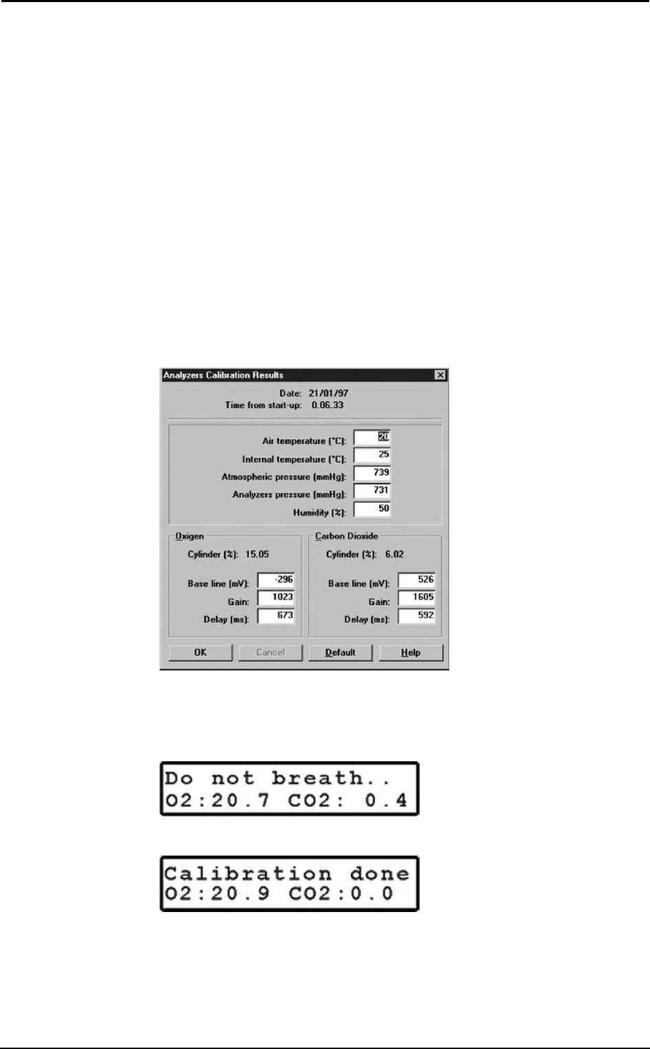
Chapter 4 - Calibration - 45
Set the reference values using the Portable Unit
To set reference values from the K4 b
2 Portable Unit go to the main menu, choose
Calibration and scroll tasks up to choose Set Cal. Predicted Values, type the values
using the arrow keys and press Enter to confirm changes.
Room air calibration
Room Air calibration is forced to be performed before each test. With this procedure the
system calibrates both gas analyzers according to the Room Air Concentrations
(20.95% O2 and 0.03% for CO2). You can run this procedure either with the software or
directly with the Portable Unit.
Room air calibration using the PC software
1. Connect the Portable Unit to the PC by the serial port. Remove the sampling plug
from the flowmeter.
2. Run the calibration program and choose Room air from the Calibration menu.
3. The message "Room air calibration in progress..." will appear and a graph will
show in real time the O
2 and CO2 calibration. At the end of the manoeuvre the
message "Calibration done" will be visualized.
4. The following dialogue box will appear showing the calibration results, press OK
to confirm the calibration.
Room air calibration using the Portable Unit
1. Remove the sampling plug from the flowmeter.
2. In the main menu choose Calibration menu, choose Room Air Calibration and
confirm by pressing Enter.
3. The procedure is automatically performed until the message "Calibration done"
appears, the O2 and CO2 values will be visualized on the display.
Reference gas calibration
The software allows to automatically calibrate zero, gain and alignments of the gases
sensors. Even if the program doesn't force you to carry out the calibration, the system
should be calibrated before each test. To perform the sensor calibration is necessary to
sss
Note: After turning on the
unit, wait 45 minutes warm
up time before starting the
calibration procedure.
sss
Important: During
calibration always remove
the sampling tube from the
optoelectronic reader. Do
not remove the sampling
tube from the Portable Unit
otherwise calibration could
be affected.
sss
Caution: During Room Air
calibration be sure to put the
sampling line far from the
expired gas otherwise
calibration could be affected.
sss
Caution: Room Air calibration
performed in small ambients
(high concentration of CO2)
affects the calibration results
and the accuracy of the
following test.
sss
Notice: Do not use mixtures
with a O2 concentration above
24% since it is out of the
oxygen sensor range
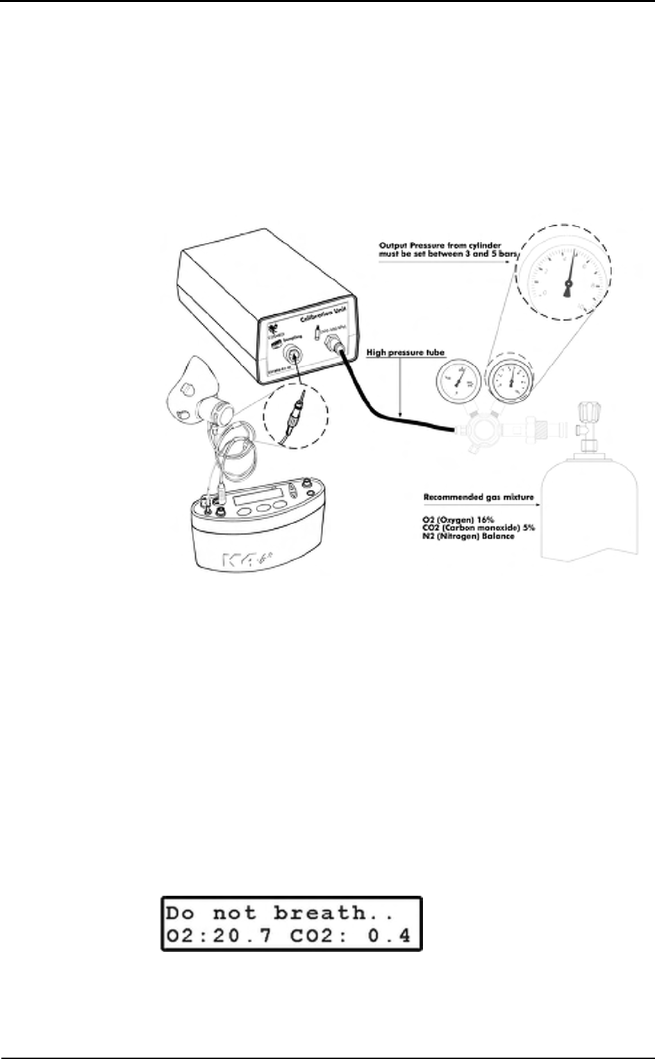
46 - K4 b2 User Manual
have available a cylinder filled of a concentration known of mixed gas. It is suggested
to use CO2 5,00% , O2 16% concentrations and N2 for balance.
The calibration unit
The gas regulator has an adjustable second stage that must be open every time the
cylinder is used for the calibration. This is necessary to avoid a small leakage in the
connections can discharge the bottle in few time.
1. Make sure you wait for warm-up time before starting calibrating. Be sure the high-
pressure tube supplied together with the system is connected to the "Cylinder" plug.
2. Open the cylinder valve by turning the valve counter-clockwise, the pressure value
must be set within a range of 300-500 Kpa (3-5 bars or 44-73 Psi).
After these operation, please operate as follows.
Reference gas calibration using the PC software
1. Connect the K4 b2 unit to the PC by the serial port. Remove the sampling plug from
the optoelectronic reader.
2. Run the calibration program and choose Gas from the Calibration menu.
3. The message "Gas calibration in progress..." will appear and a graph will show in
real time the O
2 and CO2 calibration. The software runs first the Room Air
calibration, so do not connect the sample plug to cylinder output until the message
"Sample reference gas..." will be displayed. At the end of the procedure the
message "Calibration done" will be visualized.
4. The dialogue box showing the calibration results will appear, press OK to confirm
the calibration.
Reference gas calibration using the Portable Unit
1. Remove the sampling plug from the flowmeter.
2. In the main menu choose Calibration menu, choose Refernce gas calibration and
confirm by pressing Enter.
3. The K4 b2 runs first the Room Air calibration, so do not connect the sample plug to
cylinder output until the message " Sample reference gas..." will be displayed. At
the end of the procedure the message "Calibration done" will be visualized.
sss
Notice
: Before calibrating be
sure the "Reference values"
of room air and reference
gas are properly entered.
sss
Caution: Be sure that the
cylinder pressure out is
regulated to 3 and 5 bar.
sss
Notice: If the pressure
regulator is set at a different
pressure from what
specified, room air could be
mixed together with
reference gas and the
calibration could be affected.
sss
Notice
: Before calibrating be
sure the "Reference values"
of room air and reference
gas are properly entered.
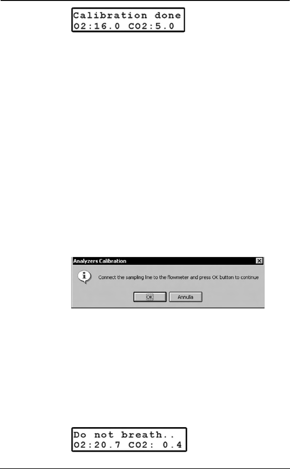
Chapter 4 - Calibration - 47
Gas delay calibration
The delay calibration procedure is a calibration included in the software due the time
alignment between flow and gas concentration measurements is one of the potential
problems to consider to assure accurate readings during test. The gas delay calibration is
the measurement of time required by the gas to reach the gas analyzer.
For "breath by breath" analysis it is essential that the instantaneous flow rate must be
multiplied by the proper time-matched expired gas concentration. Although flow can be
instantaneously measured, gas concentration measurements can be calculated with a
delay related both to the time necessary for the gas to be transported to the sensor and to
intrinsic characteristics of the analyzer principle.
Two factors contribute to the time alignments delay. K4 b2 uses a capillary sampling
tube with a pump to draw a continuous gas sample into the analyzers. The gas transport
time depends on the dimensions of the tube and on the pump flow rate. Additionally the
gas sensors have a response time that must be added to the above delay for calculating
the total delay.
The software of the K4 b2 by carrying out the Gas Delay procedure calculates this delay
and introduces a correction to realign both flow and gas measurements.
This procedure must be carried out each time some changes occur in the sampling
system, i.e. when the sampling tube is changed. However it is recommended to carry
out this calibration each week in order to prevent wrongs measurements.
Delay calibration using the PC software
1. Connect the K4 b2 unit to the PC by the serial port. Remove the sampling plug from
the optoelectronic reader.
2. Run the calibration program and choose Delay from the Calibration menu.
3. The message "Gas calibration in progress..." will appear and a graph will show in
real time the O
2 and CO2 calibration. The software first runs the Room Air
calibration. At the end of the Room Air calibration the following message appears.
4. Connect the sampling tube to the optoelectronic reader and press OK button to start
breathing at a constant rate.
5. The software helps to maintain a constant rate by means of a beep sound. It is not
important to maintain the same rate suggested by the system but it is very important
to breath constantly.
6. Continue breathing some cycles until the message "Calibration done" appears. The
software open a dialogue box with the new calibration factors and the new delay
value. Press OK to confirm the calibration.
Delay calibration using the Portable Unit
1. On the main menu scroll the commands, choose Calibration and press Enter to
confirm the choice.
2. Choose O2/CO2 delay calibration and press Enter to confirm.
3. The following message appears, and the software automatically run the Room air
Calibration.

48 - K4 b2 User Manual
4. When the message “Connect the sampling line and press Enter” appears press
Enter and start breathing at a constant rate. The software helps to maintain a
constant rate by means of a beep sound. It is not important to maintain the same
rate suggested by the system but it is most important to breath constantly.
5. After some cycles a message will appear confirming the delay calibration and the
new values will be shown on the display. Press Cancel to return to the previous
menu.
Print the calibration report
In the Calibration program choose Print from the File menu.
Edit the calibration factors
The last sensors calibration factors can be either edited or viewed. To do this choose
Gas Results… from the File menu.
To view or edit the last Turbine calibration factor choose Turbine results… from the
File menu.
Note: To restore factory setting press Default button in the dialog box. Once you press
the default button you must run a new calibration before testing.
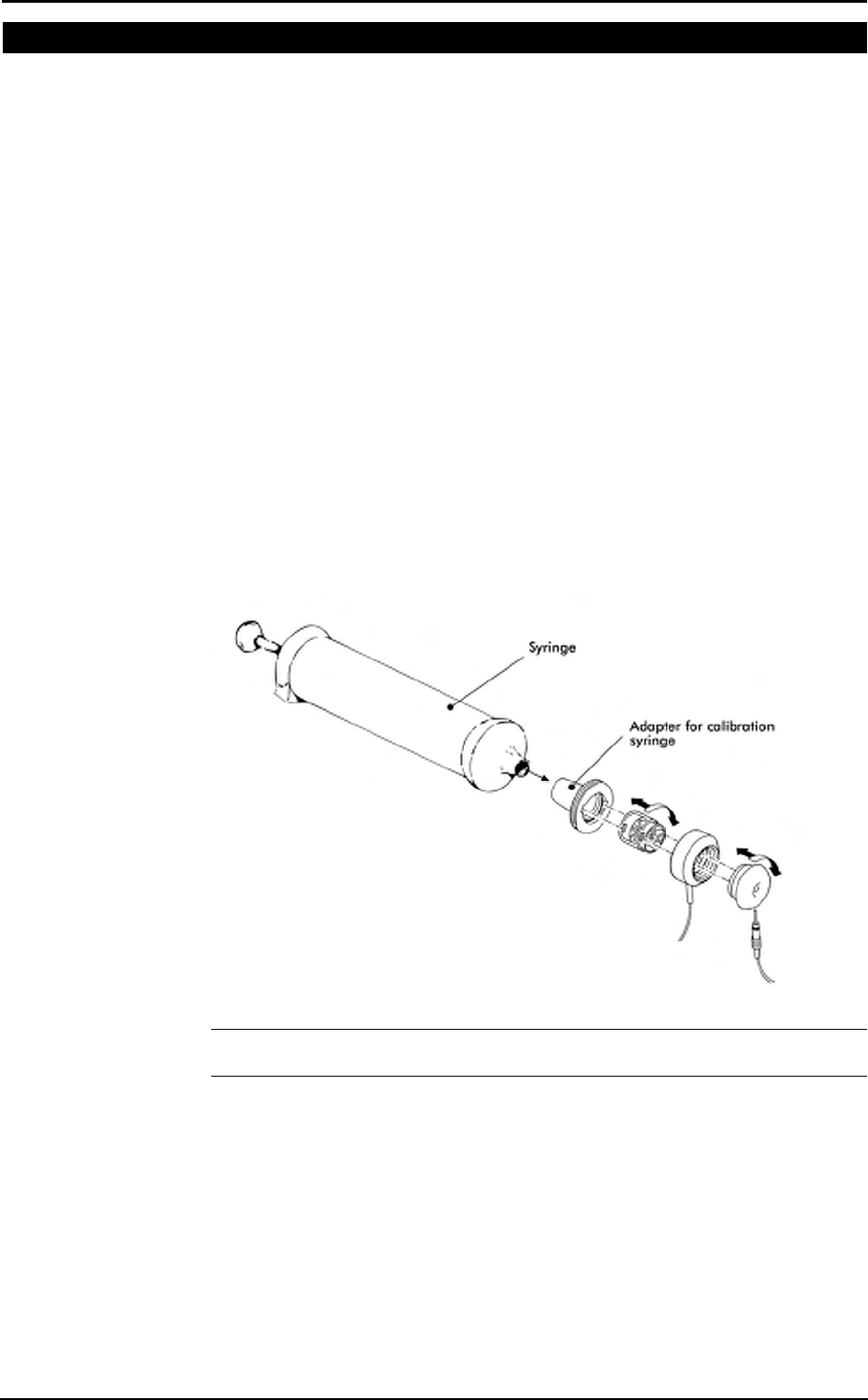
Chapter 4 - Calibration - 49
Turbine calibration
The system uses a turbine flowmeter. It opposes a very low resistance to flow. The air
passing through the helical conveyors, takes a spiral motion which causes the rotation of
the turbine rotor. The rolling blade interrupts the infrared light beamed by the three
diodes of the optoelectronic reader. Every interruption represents 1/6 turn of the rotor,
this allows to measure the number of turn in the time. There is a constant ratio between
air passing through the turbine and number of turns. This allows an accurate measure of
flows and volume. The turbine flowmeter doesn't need daily calibrations as it is not
affected by pressure, humidity and temperature.
To work properly, the turbine only requires the rotor to rotate freely without any friction
that might be caused by dust that can be easily avoided with an ordinary cleaning
procedure (see Maintenance).
However in order to ensure accuracy it's recommended to run periodically the
calibration procedure. Calibration has to be carried out with a calibration syringe of 3
litres volume, the calibration procedure is totally managed by software.
A measurement system should be calibrated daily in order to ensure maximum accuracy
and reliable test results. If a correct maintenance is provided it’s possible to check the
calibration of the turbine flowmeter even at relatively long intervals (i.e. 1 month). The
calibration procedure assures valid and verifiable results within a ±3% accuracy.
Assembling the flowmeter for calibration
1. Connect the Opto-reader to the calibration syringe through the adapter.
2. Connect the flowmeter to the syringe with the rubber cylinder supplied in the
standard packaging.
Note: If a bacterial filter is used for the tests, do use it also during the turbine
calibration.
Calibrating the turbine
Turbine calibration using the PC software
After having run the calibration program:
1. Select Reference Values from the File menu. If your syringe has a different value
from the default one (3 litres), please enter the correct value.
2. Select Calibration/Turbine….
3. When the Calibration Turbine dialog box appears with the syringe piston initially
pushed all the way in, move the piston in and out for 5 inspiratory strokes and 5
sss
Note
: If you are using a slow
PC, we recommend to set
an higher refresh time.
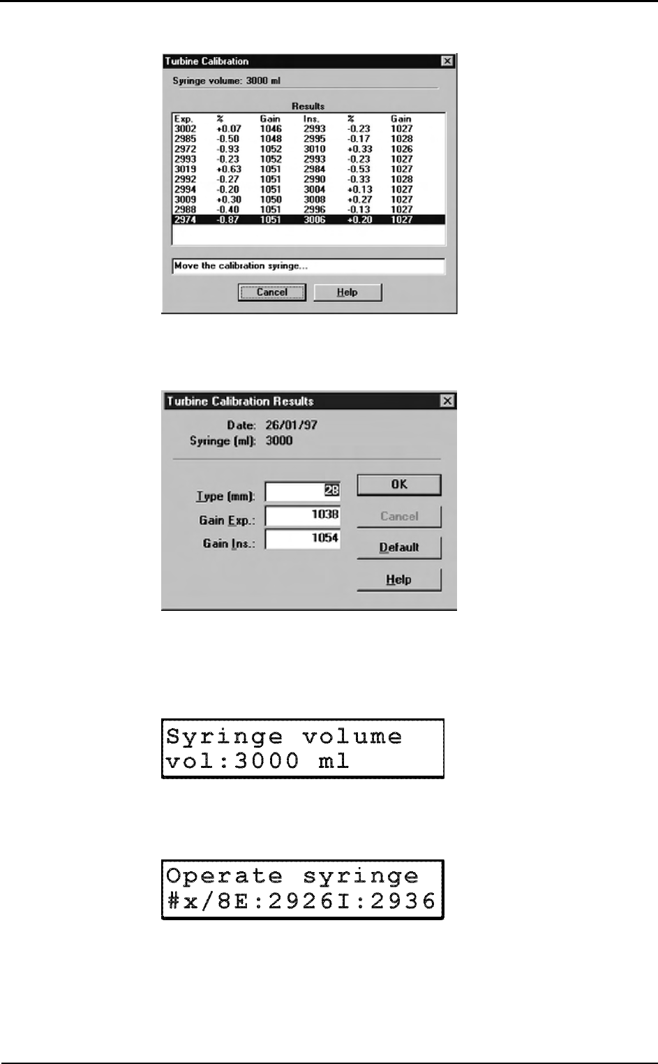
50 - K4 b2 User Manual
expiratory strokes in order to get the first values appearing on the display. Then
move the syringe piston for other 10 strokes (IN and EX).
4. At each of the 10 steps the software displays the results of the manoeuvre and the
percentage error in the reading.
5. At the end of this operation, the software displays the new calibration factors. Press
OK to store the new value.
Turbine calibration using the Portable Unit
1. Screw up the adapter for the calibration syringe to the optoelectronic reader.
2. Connect the optoelectronic reader to the calibration syringe. Before starting the
calibration be sure to have inserted the right reference value for the syringe. To
check it, select Volume Syringe from the Set predicted value menu.
3. Then choose Calibration from the main menu and press Enter.
4. Scroll the menu, choose Turbine Calibration and press Enter.
5. Start moving the syringe till the message "Operate syringe" will disappear on the
display. The display will show expired (E) and inspired (I) readings for each stroke.
6. When the display visualizes the message "Calibration done" the Turbine has been
calibrated, press Cancel to return to the main menu, the new calibration factor will
be automatically stored.
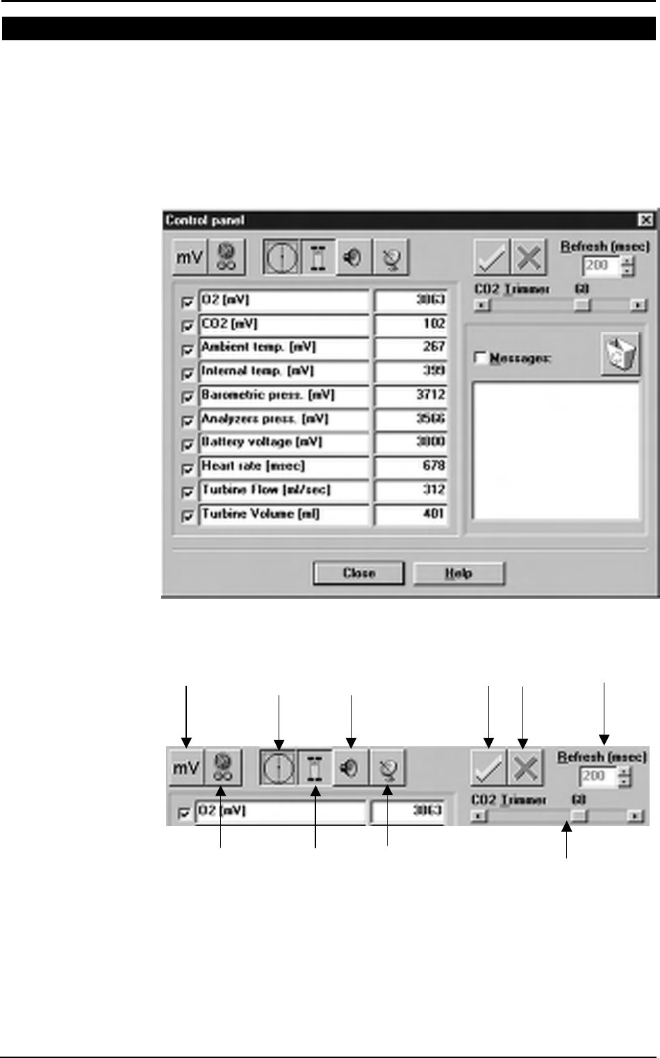
Chapter 4 - Calibration - 51
Checking the system signals
The control panel
The Control Panel, which can be activated from the Calibration/Control panel…
menu item, is a useful tool to check the main hardware functions of K4 b2.
By using the controls on Control Panel you are able to do the following:
1. Reading the signals acquired by the system both as voltages and processed data;
2. Activating/Disactivating the valves, the sampling pump and other installed
components (for example, oxymeter).
Using the control panel
mV / real values
display
Select all
channels
Deselect all
channels
Signal refresh
time
Sampling
pump on/off
edit parameters
(name, unit,…)
Flowmeter
on/off
Buzzer
on/off
Transmitter
on/off
Digital CO
2
trimmer

52 - K4 b2 User Manual

Operating modes

54 - K4 b2 User Manual
K4 b2 Operating modes
K4 b2 is a versatile system. You can use it in the field or in the lab without any kind of
limitation. Test can be carried out in the following three different configuration:
• Holter Data Recorder
• Telemetry Data Transmission
• Laboratory Station
Holter Data Recorder
Using the system in the field without the Receiver unit you can store data "breath by
breath" in high capacity memory (1 MB). The memory allows to store up to 16
thousands breaths, when the test is completed, the results can be downloaded to the PC
via the RS 232 port provided with the equipment.
Telemetry Data Transmission (option)
In case the telemetry Data Transmission module is available, the K4 b2 portable unit
provided with a small transmitter that allows to send data by telemetry up to a distance
of 800 meters. All data are transmitted "breath by breath" to the receiver unit. The
Receiver Unit must be connected to a PC by serial port, it allows the resercher to
monitor data on line both in table and graphic format. Anyway tests are stored in the
memory of the portable unit, thus in case of transmission interferences no data are lost.
By using the system with a PC the software K4 b
2 can also control and synchronise
ergometers by using user defined exercise protocol.
Serial (Laboratory) Station
Although K4 b
2 has been designed for tests in the field, it can also be used as a
conventional laboratory station as it offers the same features of the best stand alone
devices. Under this operating mode the K4 b2 Portable Unit is simply connected to the
PC through the RS232 serial port and all tasks, exactly like any conventional laboratory
device. Anyway tests are stored on the memory of the portable unit as well.
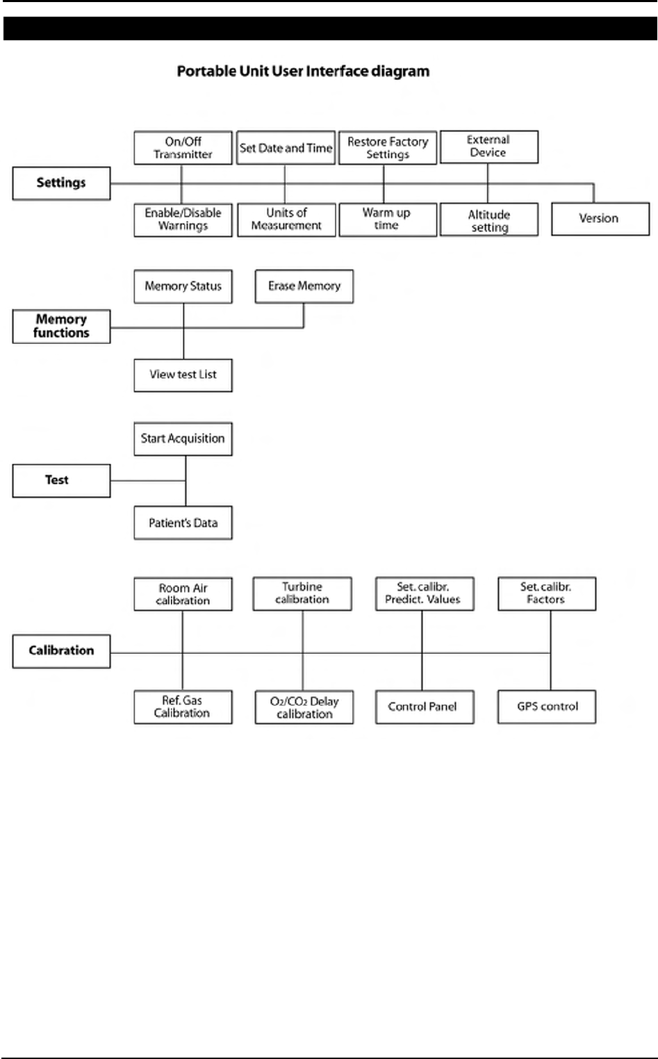
Chapter 5 - Operating modes - 55
Portable Unit User Interface diagram
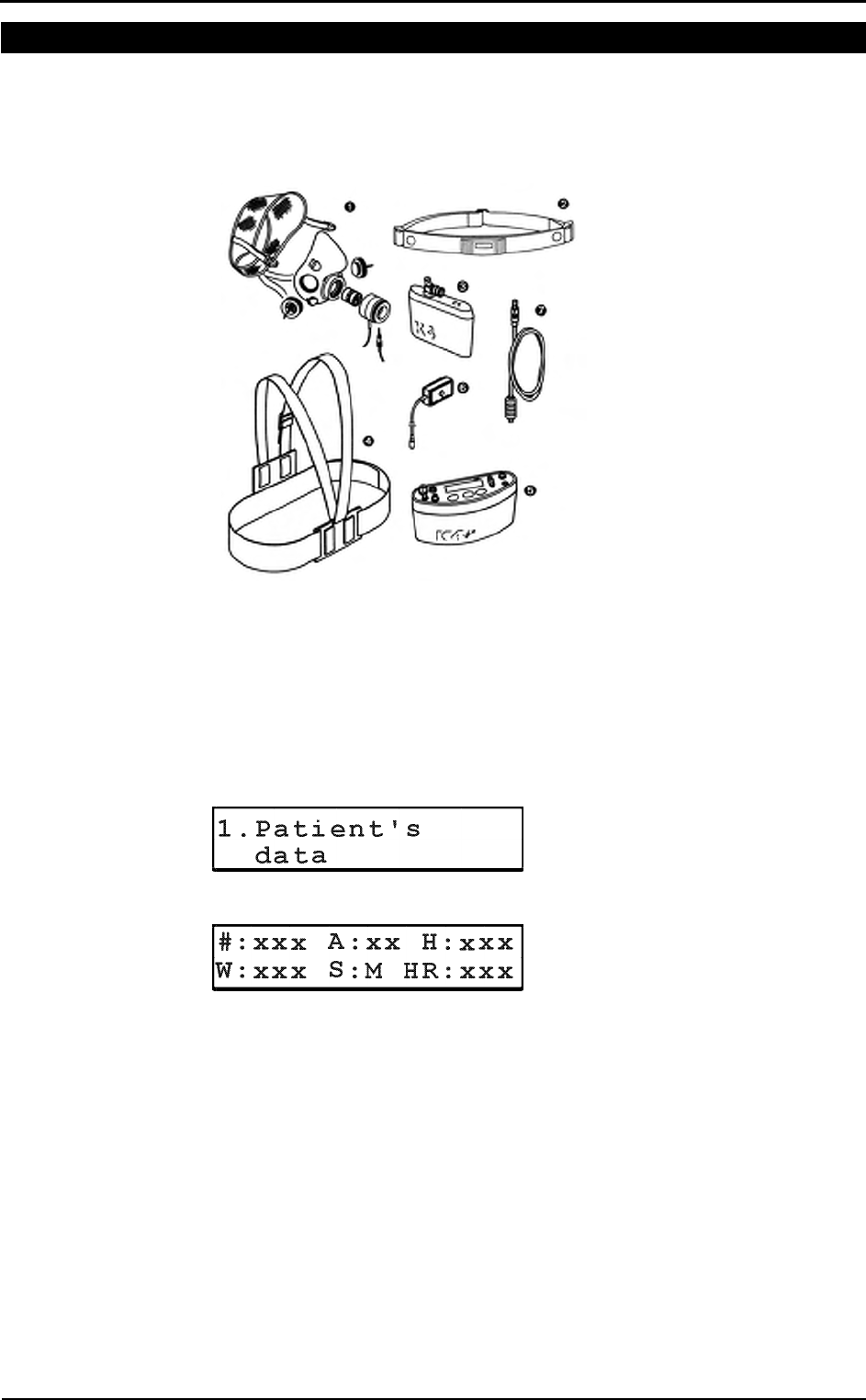
56 - K4 b2 User Manual
Holter Data Recorder Mode
It is ideal operating modes if you need to test a patient difficult to monitor by Telemetry
(i.e. climbing, long distances races, etc). The memory capacity of the K4 b2 is able to
store data up to 16 thousands breaths. The system saves data for each breath, hence time
storing capacity depends on the respiratory frequency.
1. Mask + flowmeter
2. Heart rate belt
3. Rechargeable battery
4. Harness
5. K4 b2 Unit
6. HR probe
7. Power cable
Operating sequence
Warming-up the system
Warm-up the K4 b2 for 45 minutes before testing or calibrating.
Enter new patient
1. Connect K4 b2 to the subject.
2. Go to the K4 b2 control panel and choose Patient's data from Test menu.
3. Move the cursor among fields with the Enter key and use the Up and Down keys
to modify values.
The fields are shown in the following order:
#: patient ID
A: age in years
H: height (cm or inch)
W: weight (kg or Lbs)
S: sex (M or F)
HR: HR max
4. The HR Max is automatically calculated by the formula 220-age, however it can be
also changed according to physician experience and patient medical history. By
confirming the HR rate value all the patient data are automatically saved.
Calibrate and start the test
1. Remove the sampling plug from the mask and put the tube far from expired gas
concentrations.
2. On the Patient's Data menu scroll down the menu and select Start Test from the
main menu and press Enter to confirm.
sss
Note: USA and Japan
versions have the items 3
and 5 slightly different
because of the antenna
placement.
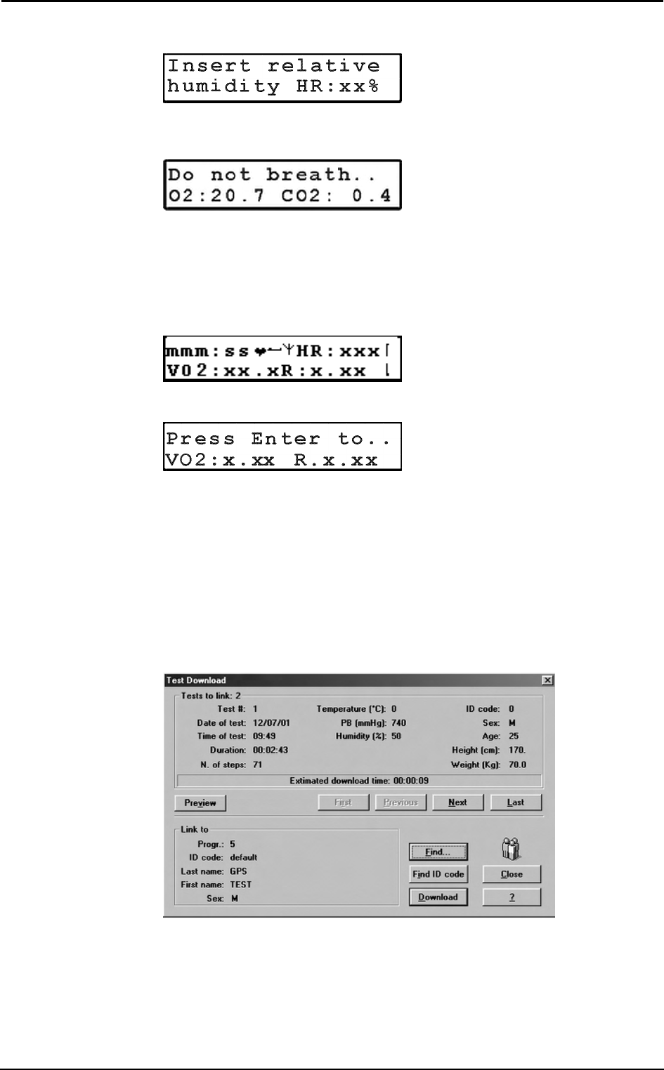
Chapter 5 - Operating modes - 57
3. The message "Insert relative humidity" will be visualized, type the correct value
and press Enter.
4. The K4 b
2 runs automatically the Room Air calibration. The message "Do not
breath near the sampling line" appears. Wait for few seconds until the message
"Calibration done" will appear together with a double beep sound.
5. Connect the sampling plug to the optoelectronic reader. Some values (Heart Rate,
R, VO2, VCO2,...) will be shown and updated each breath on the control panel
display. The message "Press Enter to start the test" will be displayed each 10 secs.
You can switch to different values by moving the Up and Down key.
6. After having pressed the Enter key the test starts but the K4b2 is not storing data.
In this phase the PU is checking the main parameters and you can visualize it on the
PU display by the time is blinking.
7. To start storing data press another time the Enter key. You can check the storing
phase because the time parameter don't blink anymore.
Stop the test
To stop the test press Cancel. The message "Press enter to stop test" will appear, press
Enter to stop the test.
Transferring test to PC
Once the test is concluded you may download all data stored in the K4 b
2 to the
management software.
1. Turn the K4 b2 on.
2. Connect the K4 b2 to the PC by the serial cable enclosed in the equipment.
3. Run the K4 b2 software and choose Receive Test from the Test menu.
4. To download a test you must link it to an existing patient file. Choose Find and
then List to select an existing patient. If the patient is new than select Find and then
New, fill in the fields and press OK to confirm.
5. Select the test to link by using First, Previous, Next and Last buttons and press
Download to confirm your choice and to store the test on the Hard Disk. You can
use the Preview button to see some data and graph of the test in order to find out
the proper one.
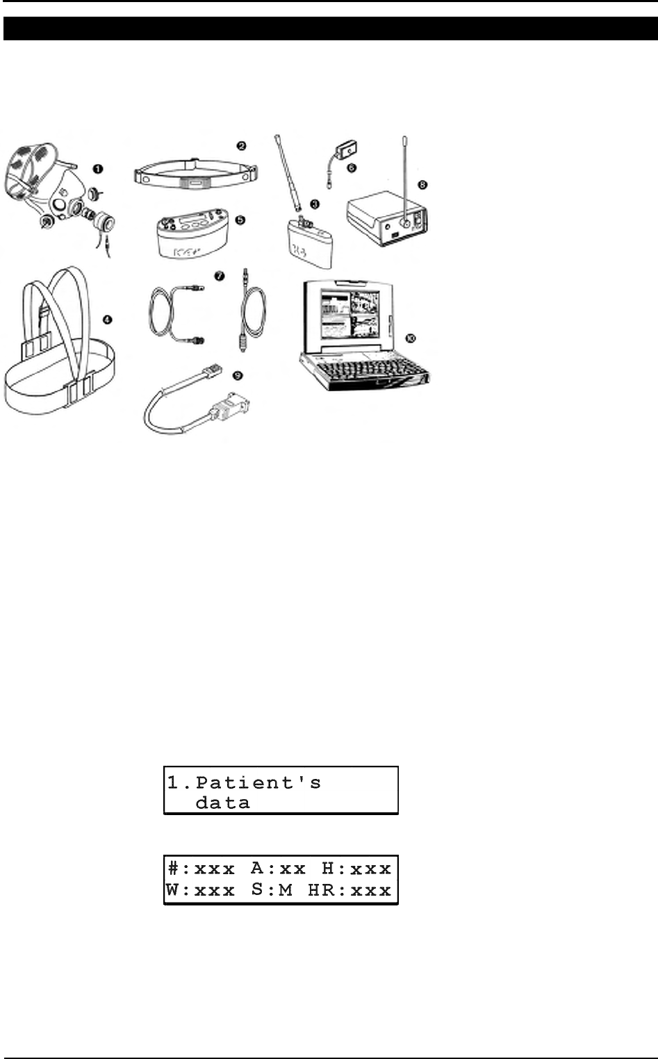
58 - K4 b2 User Manual
Telemetry Data Transmission Mode
In case you need to monitor in real time the test you can use the Telemetry Data
Transmission module that is provided by COSMED as an option. The transmission
range can reach 800 m allowing to monitor exercise testing in the field. To use this
option you need a personal computer to connect the receiver unit.
1. Mask + flowmeter
2. Heart rate belt
3. Rechargeable battery + antenna
4. Harness
5. K4 b2 Unit
6. HR probe
7. Power cable + antenna
8. Receiver unit
9. RS232 cable
10. Personal computer
Operating sequence
Warming-up the system
Warm-up the K4 b2 for 45 minutes before testing or calibrating.
Connect the receiver unit to the PC
Connect the receiver unit to PC with the serial cable provided in the standard packaging.
Enable transmission
1. Go to the K4 b
2 control panel, verify that transmission is enabled by choosing
Settings /On/Off Transmitter and press Enter.
2. Enable the transmission by moving the "*" sign on Transmit. On and press Enter
to confirm settings.
Enter new patient
1. Connect K4 b2 to the subject.
2. Go to the K4 b2 control panel and choose Patient's data from Test menu.
3. Move the cursor among fields with the Enter key and use the Up and Down keys
to modify values.
The fields are shown in the following order:
#: patient ID
A: age in years
H: height (cm or inch)
W: weight (kg or Lbs)
S: sex (M or F)
HR: HR max
sss
Note: USA and Japan
versions have the items 3
and 5 slightly different
because of the antenna
placement.
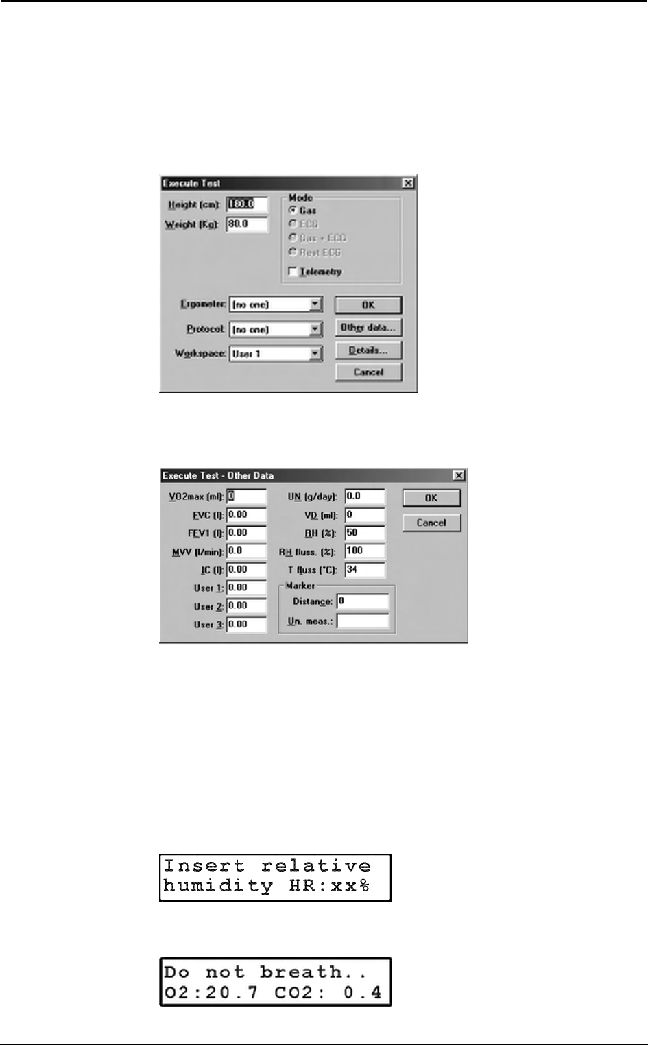
Chapter 5 - Operating modes - 59
4. The HR Max is automatically calculated by the formula 220-age, however it can be
also changed according to physician experience and patient medical history. By
confirming the HR rate value all the patient data are automatically saved.
Enable reception on PC
1. Run K4 b2 software.
2. Open patient data dialog box, select or type a new name and press OK to confirm.
The name of the selected patient will appear in the status bar of the software.
3. Choose Execute test from the Test menu.
4. Type the patient information, select a protocol from the list and an ergometer if
you are going to carry out a test with an ergometer.
5. Chose Other Data if you want to insert other important informationon the the you
are going to perform.
6. Select the workspace you would like to see during the test (it can be also changed
during test), check the option box Telemetry to enable software receiving of data
and press OK to confirm. The software will show blank windows waiting for the
first breath.
Calibrate and start the test
1. Remove the sampling plug from the mask and put the tube far from expired gas
concentrations.
2. On the Patient's Data menu scroll down the menu and select Start Test from the
main menu and press Enter to confirm..
3. The message "Insert relative humidity" will be visualized, type the correct value
and press Enter.
4. The K4 b
2 runs automatically the Room Air calibration. The message "Do not
breath near the sampling line" appears. Wait for few seconds until the message
"Calibration done" will appear together with a double beep sound.
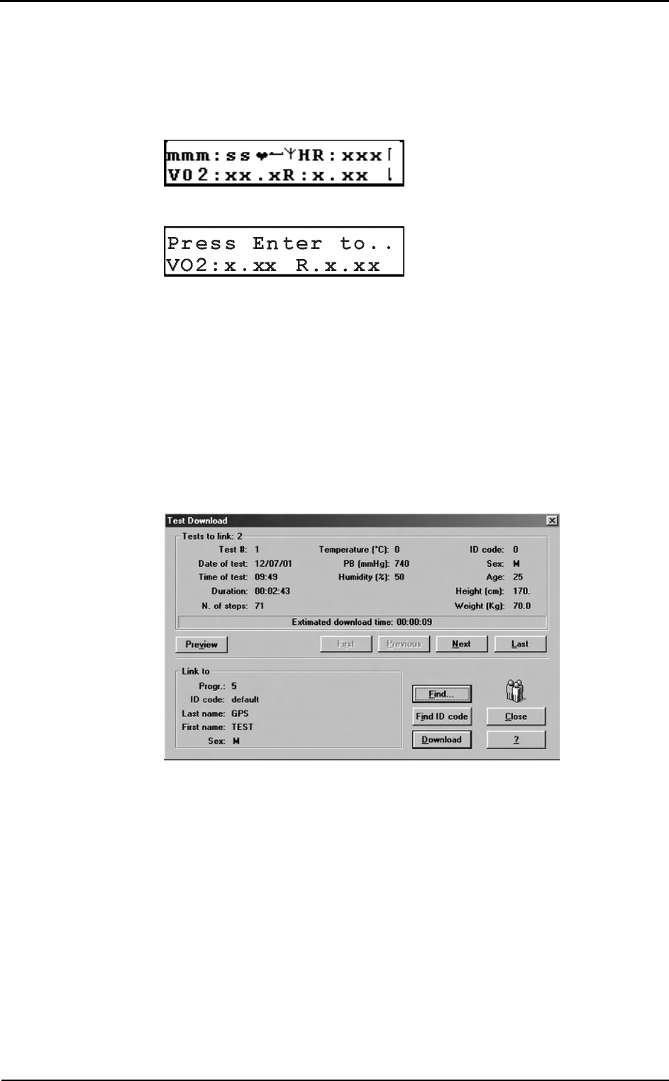
60 - K4 b2 User Manual
5. Connect the sampling plug to the optoelectronic reader. Some values (Heart Rate,
R, VO2, VCO2,...) will be shown and updated each breath on the control panel
display. The message "Press Enter to start the test" will be displayed each 10 secs.
You can switch to different values by moving the Up and Down key.
6. After having pressed the Enter key the test starts but the K4b2 is not storing data.
In this phase the PU is checking the main parameters and you can visualize it on the
PU display by the time is blinking.
7. To start storing data press another time the Enter key. You can check the storing
phase because the time parameter don't blink anymore.
Stop the test
To stop the test press Cancel. The message "Press enter to stop test" will appear, press
Enter to stop the test.
Transferring test to PC
If some interferences should occur during test execution by telemetry, some breaths
could be lost. The software shows a message on the status bar warning that some steps
missed . Since K4 b2 stores every time the complete test in the memory, it is possible to
download the test later to the management software to recover all lost data.
1. Turn the K4 b2 on.
2. Connect the K4 b2 to the PC by the serial cable enclosed in the equipment.
3. Run the K4 b2 software and choose Receive Test from the Test menu.
4. To download a test you must link it to an existing patient file. Choose Find and
then List to select an existing patient. If the patient is new than select Find and then
New, fill in the fields and press OK to confirm.
5. Select the test to link by using First, Previous, Next and Last buttons and press
Download to confirm your choice and to store the test on the Hard Disk. You can
use the Preview button to see some data and graph of the test in order to find out
the proper one.
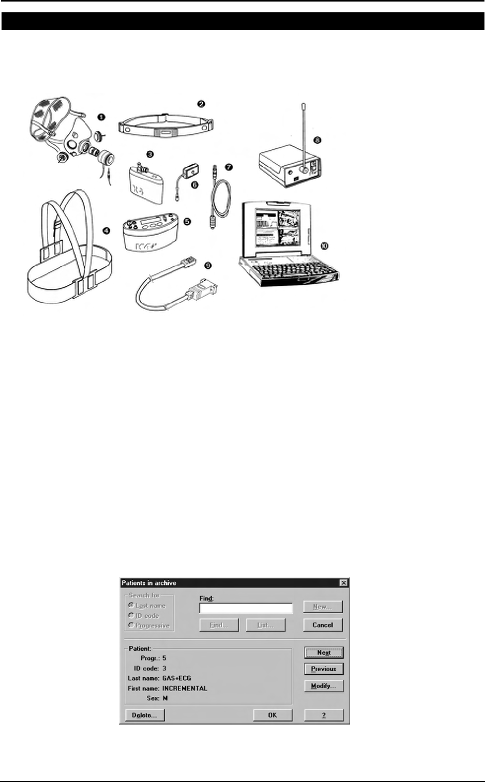
Chapter 5 - Operating modes - 61
Serial Mode
When the K4 b
2 is used in the serial mode the system works exactly as any other
conventional laboratory station. In this mode the software controls completely the K4 b2
portable unit so that any command such as calibration can be run by the software. You
can also drive an ergometer if a second serial port is available in the PC.
1. Mask + flowmeter
2. Heart rate belt
3. Rechargeable battery
4. Harness
5. K4 b2 Unit
6. HR probe
7. Power cable
8. Receiver unit
9. RS232 cable
10. Personal computer
Operating sequence
Warming-up the system
Warm-up the K4 b2 for 45 minutes before testing or calibrating.
Connect the Portable unit to the PC
1. Connect K4 b2 to the PC by the serial cable
2. Check that the Serial Port is properly selected by choosing RS 232 from the Option
menu.
3. Check the Ergometer connected to PC option box if you intend to use an
ergometer for testing.
Calibrate the system
1. Run the K4 b2 software and choose Calibration from the Test menu.
2. In the Calibration software select Analyzers -> Room Air from the Calibration
menu.
Enter patient data
1. In the K4 b2 software and choose Patient from the File menu.
2. Select a patient from the list or press New to enter a new name and press OK to
confirm.
sss
Note: USA and Japan
versions have the items 3
and 5 slightly different
because of the antenna
placement.
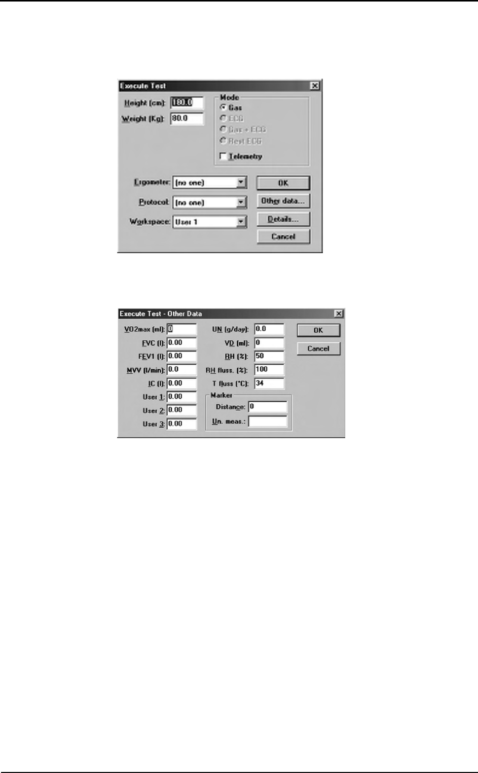
62 - K4 b2 User Manual
Start the test
1. Open patient data dialogue box, select or type a new name and press OK to
confirm. The name of the selected patient will appear in the status bar of the
software.
2. Choose Execute test from the Test menu.
3. Type the patient information, select a protocol from the list and an ergometer if
you are going to carry out a test with an ergometer.
4. Chose Other Data if you want to insert other important informationon the the you
are going to perform.
5. Select the workspace you would like to see during the test (it can be also changed
during test) and be sure that option box Telemetry is disabled since the
transmission will be done by serial cable. Press OK button to start acquisition.
6. The software displays the data according to the selected workspace. Check some
breaths and press F2 to start testing.
Stop the test
To end the test press F3, press OK in the following dialogue box to confirm the end of
the test. All data will be automatically saved on the Hard disk. Anyway test is stored on
the memory of the portable unit as well.

Database
Management
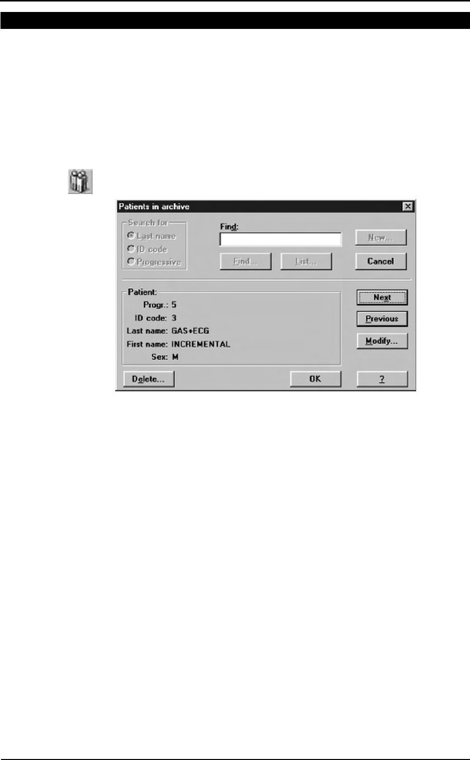
64 - K4 b2 User Manual
Exercise testing patient's database
The exercise testing software uses a different interface for presenting patient
information. The patient database allows to:
• Enter a new patient
• Find patient data
• Edit patient data
• Delete patient data.
Select Patients from the File menu.
Enter a new patient
1. Press New to show the Patient dialog box.
2. Enter data of a new patient and press OK button to confirm.
Find a patient
Enter a search string into the Find field and press Find to view the data concerning a
subject already in the database. You can search for “Last name”, “ID code” or
“Progressive”.
Or:
Press List to view the list of patients in the database. Press Next or Previous to view
the data corresponding to the next or to the last patient. Press OK to confirm.
The Next and Previous buttons allow to move to the next or the previous patient in the
database.
Edit patient data
1. Select the patient.
2. Press Modify… in order to edit the patient’s data.
3. Edit the desired values and press OK to confirm.
Delete a patient
1. Select the patient to be deleted.
2. Press Delete.
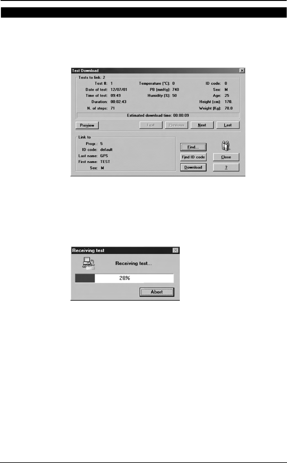
Chapter 6 - Database Management - 65
Uploading tests from the Portable Unit
In telemetry and holter function you could need to upload data from the portable unit
via serial port.
1. Link up the PU to the PC with the RS232 cable supplied.
2. Turn on the Portable Unit.
3. Choose Receive Test from Test menu or press Alt F2.
4. To be downloaded the test must be linked to a patient. If the current patient has
already been inserted in the database, choose Find and then List select the patient
and confirm. If the current patient doesn't belong to the archive he must be inserted,
select Find and then New, fill in the fields and confirm. Now the download
function is available and the test will be filed on the PC.
5. Choose the test to link with the First, Previous, Next and Last buttons and press
Download.
6. A status bar will show the data acquisition in progress. At the end a message will
indicate the end of data reception.
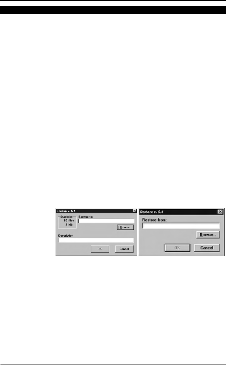
66 - K4 b2 User Manual
Archive maintenance
The software allows to manage files selecting Archive from the File menu.
It is advisable to perform the archive reorganisation every month, in order to free space
on the hard disk and/or to correct possible errors present within the database.
It is possible also that your have no more hard disk space. So, you have to delete all the
data. In this case, it is useful to perform the initialising.
Reorganise the archive
1. Select Reorganize archive from the File menu.
2. Wait for the end of the operation before performing any other function.
Delete the archive
1. Select Initialize Archive from the File menu.
2. Wait for the end of the operation before performing any other function.
Delete a test
To delete an ergometry test, select Test/Delete test.
To delete a spirometry test, press the proper button in the Test Card.
Backup and restore
It is strongly recommended to backup files, a warning message will be displayed
monthly. This function allows the user to restore the data if the PC or the HD will not
work anymore.
Backup
1. Select Backup archive from the File menu.
2. Selecting the destination path with the Browse key or press New to create a new
directory. Press OK to confirm.
3. In the dialog box it will appear an estimate of the number of floppy disks you need
in order to back up the archives. Press OK.
Restore
1. Select Restore archive from the File menu.
2. On the Restore dialog box specify the drive source and press OK, a dialog box
will appear indicating all data of the backup processed.
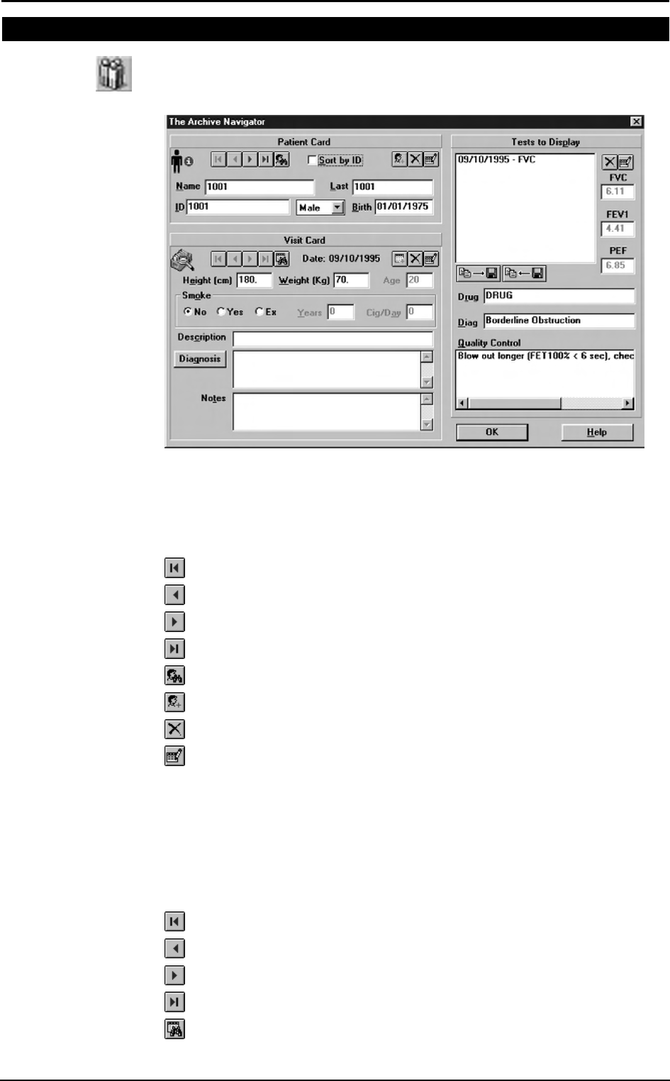
Chapter 6 - Database Management - 67
Spirometry patient's database
The Patients database consists of a Patient Card, a Visit Card and a Test Card in which
are listed all tests performed by the patient.
Select Archive Navigator from the File menu or press the button by side.
Patient Card
It collects all the information of a patient (first name, last name, date of birth) which
remain the same for each visit. For each patient there is only one Patient Card, which is
created the first time the Patient performs a test.
To move within the database use the following buttons:
Move to the first patient in the archive
Move to the previous patient in the archive
Move to the next patient in the archive
Move to the last patient in the archive
Find a patient in the archive
Enter a new patient in the archive
Delete current patient from the archive
Edit the current patient card
Visit Card
It collects all information relative to the visit (diagnosis, visit description...) and to the
patient information subject to change between one visit and another (height, weight,
smoke). Each patient can be related to several Visit Cards provided they have been
created in different days. Before carrying out any spirometric test it is necessary to
create a new Visit Card or to open the today’s Visit Card.
To move within the database use the following buttons:
Move to the first visit in the archive
Move to the previous visit in the archive
Move to the next visit in the archive
Move to the last visit in the archive
Find a visit in the archive
sss
Note: after having deleted a
record (patient, visit or test),
it is recommended to
reorganize the archive in
order to free disk space.

68 - K4 b2 User Manual
Enter a new visit card in the archive
Delete current visit card from the archive
Edit the current visit card
Test Card
It contains all the information about the test.
To move within the database use the following buttons:
Delete current test from the archive.
Edit the current test
Import/export a Tests card
This function allows to import /export a test card with the respective visit and patient
card.
1. Select the patient.
2. Choose the test and press the key by side. All data will be imported/exported in the
XPO file format (Cosmed proprietary).
Diagnosis Database
The program allows to manage a diagnosis database, whose records are composed by a
diagnosis ID code and a string of text.
The report of the visits can be done either by typing the desired text in the field
“Diagnosis” of the Visit Card or, more quickly, retrieving from the diagnosis database
the desired one.
If you want to insert, modify or delete a diagnosis from the database select Database
Diagnosis... from the File menu.

Chapter 6 - Database Management - 69
Spirometry program settings
The software allows to configure some options selecting Configure from the Option
menu.
Graphs
All the graphs visualised and/or printed can be customised in colours and appearance.
1. Select the desired colours of the curves (5 curves max can be overlapped on the
same graph).
2. Enable or disable the Grid option.
3. Enable or disable the Show Info Test option.
Serial port
You must select the serial port RS 232 that will be used to connect the Quark b2 with the
PC.
To select the serial port, click on the proper COM button (the selected port must be
different from the mouse one).
Units of measurements
It is possible to configure the units of measurements, weight and height, for printing and
viewing.
To select the units of measurement click on cm/Kg or in/lb according to the desired
format.
Using extra fields
The Patient’s database is organised in 3 different cards (Patient card, Visit Card and
Test card.) where it is possible to store the information about patients and visits .
Besides the standard information, it is possible to customise some fields (user free
fields), entering and labelling measurements coming from other devices.
The customisable free fields are:
• 3 fields in the Patient Card (Patient’s information)
• 3 fields in the Visit Card (information about the visits)
• 3 fields (2 numeric) in the Test card information about Test)
Customise the fields
In the group User free fields type the desired text in the 9 fields available.

70 - K4 b2 User Manual