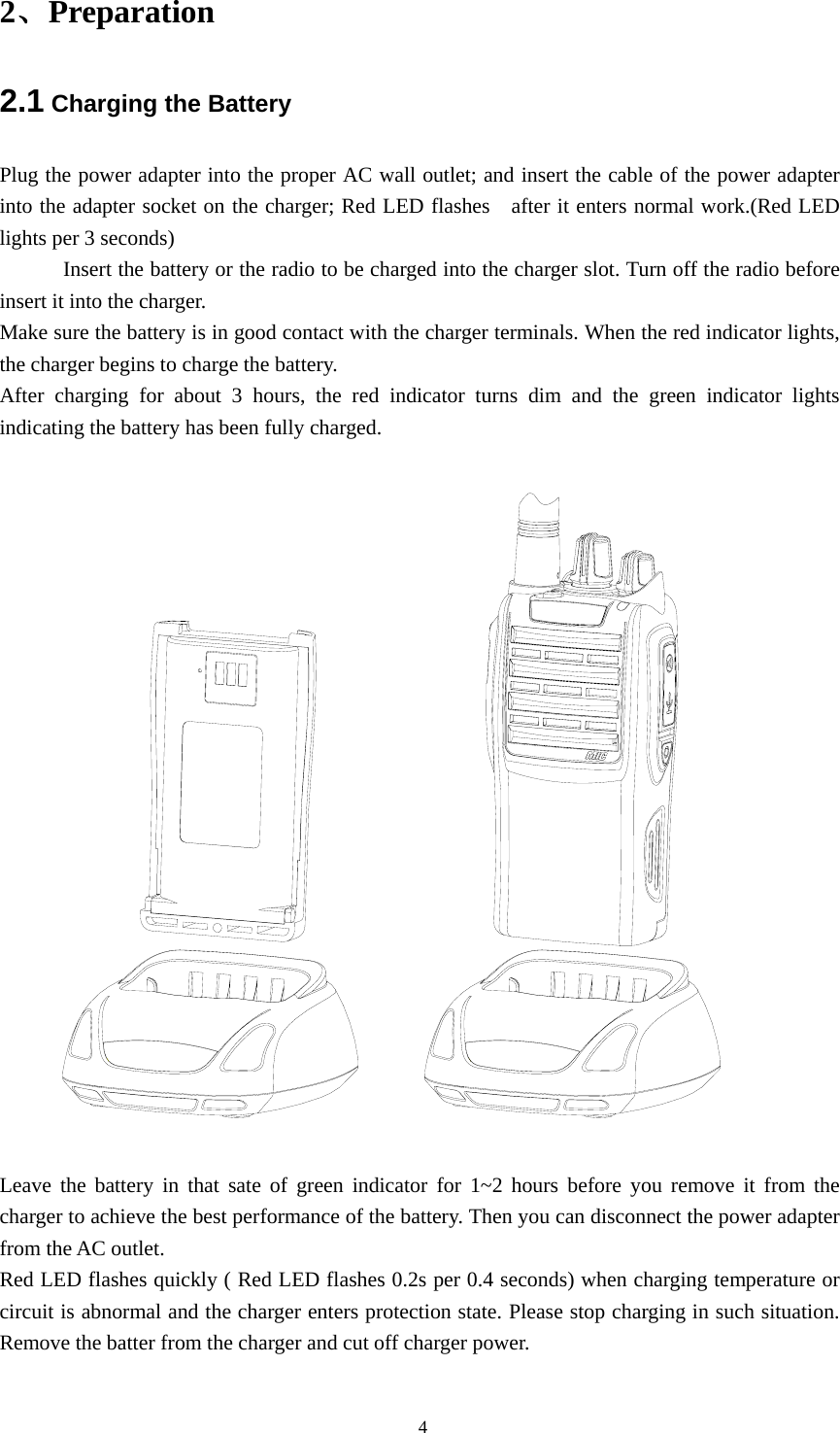
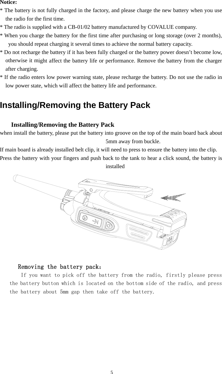
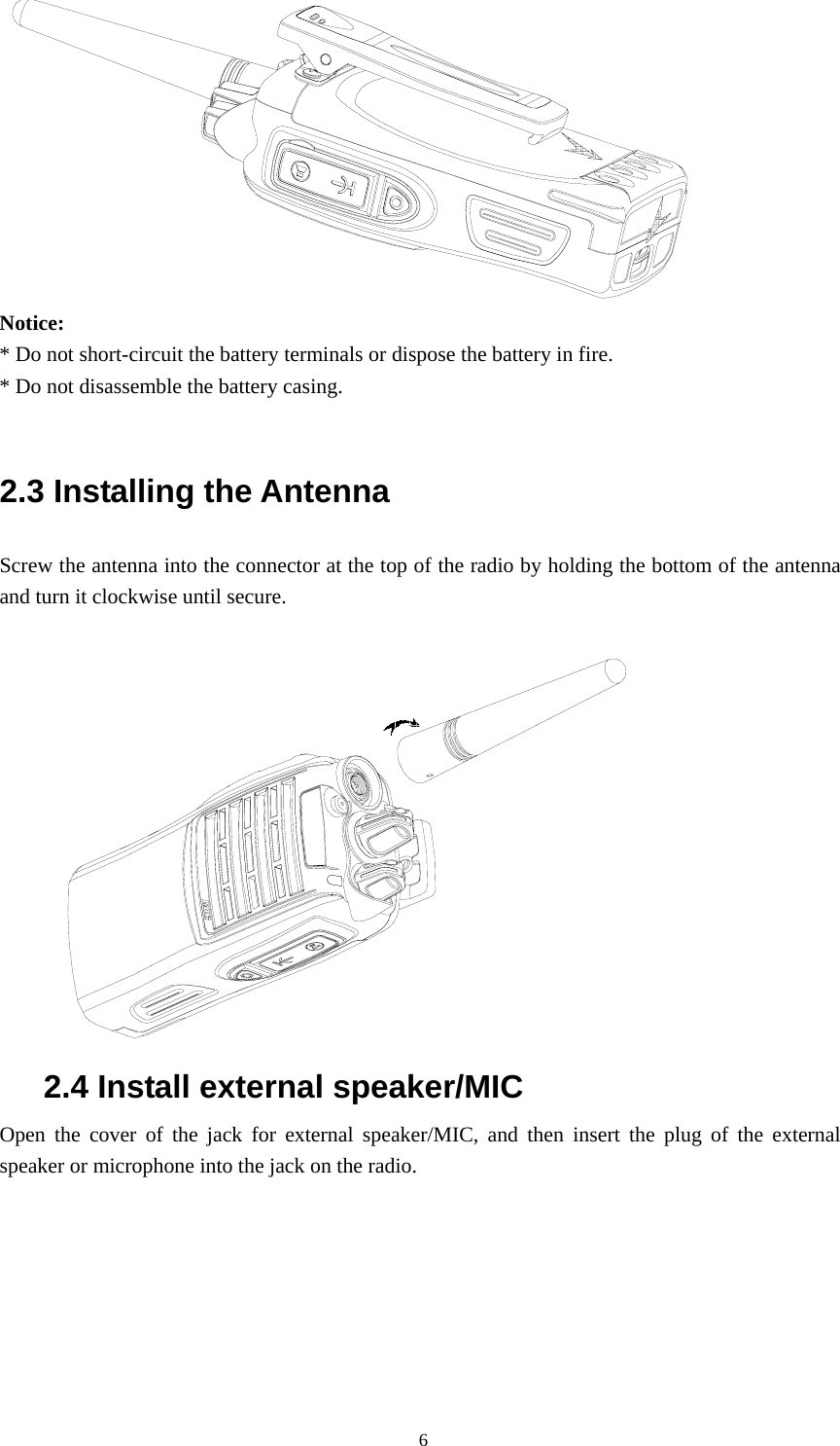
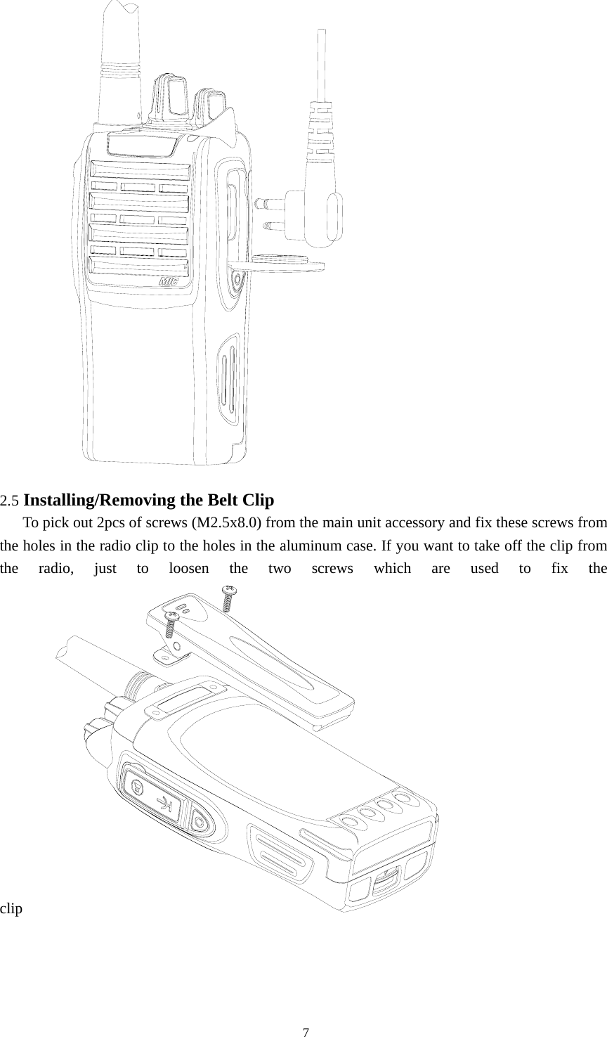
COVALUE COMMUNICATIONS CU600-2 Two Way Radio User Manual Instruction Manual

SHENZHEN COVALUE COMMUNICATIONS CO., LTD. Two Way Radio Instruction Manual

user manual

  Instruction Manual     CU600-2Two Way Radio    Notice to the User: ·  Please read this instruction manual before operating this radio.   ·  It’s prohibited to use the radio or charge it at any area with a potentially explosive atmosphere (where the air contains gas, dust and smog, etc.), such as while taking on fuel, or while parking at a gasoline service station; or any area where radio communication is prohibited (such as a hospital or a airport.) ·  It’s prohibited to operate the radio without permission at the areas where the government laws prohibit radio communication. ·  Please don't expose the radio to direct sunlight for a long time; don't place the radio near any heating devices, either. ·  Please don't put the radio in extremely dusty, moist or dabbling places; don’t place it on any unstable surfaces, either.   ·  If you want to develop or remodify the radio   · Refer service to the well-trained professional technicians only and do not disassemble or assemble the radio.        SHENZHEN COVALUE COMMUNICATIONS Co., Ltd.                                                       1
W AR N IN GYour radio generates RF electromagnetic en-ergy during transmit mode. This radio is designed for and classified  as “Occupational  Use  Only”, meaning it must be used only during the course of employment by individuals aware of the hazards, and the ways to minimize such hazards. This radio is NOT intended for use by the “General Population” in an uncon-trolled environment.This radio has been tested and complies with the FCC RF ex-posure limits for “Occupational Use Only”. In addition, your radio complies with the following Standards and Guidelines with regard to RF energy and electromagnetic energy levels and eval-uation of such levels for exposure to humans:  •  FCC OET Bulletin 65 Edition 97-01 Supplement C, Evaluat-ing Compliance with FCC Guidelines for Human Exposure to Radio Frequency Electromagnetic Fields.  •  American National Standards Institute (C95.1-1992), IEEE Standard for Safety Levels with Respect to Human Exposure to Radio Frequency Electromagnetic Fields, 3 kHz to 300 GHz.  •  American National Standards Institute (C95.3-1992), IEEE Recommended Practice for the Measurement of Potentially Hazardous Electromagnetic Fields– RF and Microwave. •  The following accessories are authorized for use with this product. Use of accessories other than those specified may result in RF exposure levels exceeding the FCC requirements for wireless RF exposure.; Belt Clip, Rechargeable Li-Ion Battery Pack, Charger.C AU T IO NTo ensure that your expose to RF electromag-netic energy is within the FCC allowable lim-its for occupational use, always adhere to the following guidelines: •  DO  NOT operate the  radio without  a  proper antenna at-tached, as this may damaged the radio and may also exceed FCC RF exposure limits. A proper antenna is the antenna supplied with this radio or antenna specifically authorized for use with this radio.  •  DO NOT transmit for more than 50% of total radio use time (“50% duty cycle”). “50% duty cycle” is also applicable to PSTN (Public Switched Telephone Network) mode and VOX      Mode.Transmitting more than 50% of the time can cause FCC       RF exposure compliance requirements to be exceeded. The       radio is transmitting when the TX indicator lights red. You can       cause the radio to transmit by pressing the “PTT” switch.     •  ALWAYS keep the antenna at least 2.5 cm (1 in.) away from     the body when transmitting and only use the Icom belt-clips     listed on p. 24 when attaching the radio to your belt, etc.,     to ensure FCC RF exposure compliance requirements are     not exceeded. To provide the recipients of your transmission     the best sound quality, hold the antenna at least 5 cm (2 in.)     from your mouth, and slightly off to one side.         The information listed above provides the user with the informa-         tion needed to make him or her aware of RF exposure, and what          to do to assure that this radio operates with the FCC RF expo-         sure limits of this radio.25SAFETY TRAINING INFORMATION
CONTENTS  ■  Unpacking and Checking the Equipment     Supplied Accessories   ■ Preparation  Charging the Battery Installing/Removing the Battery Pack Installing the Antenna Installing the Optional Speaker/Microphone Installing/Removing the Belt Clip ■ Radio Overview  ■ Basic Operations ■  Programmable Button Function ■  VOX (Voice Operated Transmission) ■ Wired Cloning Mode ■ Radio Setting TOT (Time-out Timer) Battery Save Low Power Warning Channel Annunciation CTCSS/DCS ■ User Template RX Squelch Mode DTMF 5-Tone Signaling ■  Troubleshooting ■  Settings                                                               2
■  Unpacking and Checking the Equipment Unpack the radio carefully. We recommend that you identify the items listed in the following table before discarding the packing material. If any items are missing or have been damaged during shipment, please contact the carrier or the dealer immediately.   Supplied Accessories Item Quantity Antenna 1 Hand Strap  1 Belt Clip  1 Lithium Battery    1 Charger 1 Power Adapter  1 Dust Cover  1 Instruction Manual  1    Antenna Power Adapter Belt Clip Charger Hand Strap Li-Polymer Battery  1、Open Package Inspection Firstly, please take the radio out of the package box carefully. We recommend checking the radio and the supplied accessories in the following table carefully. If any article is found lost or   damaged, please contact the distributor without delay.  Package List  Accessories  Quantity 1  Mainframe  1 2  Antenna  1 3  Battery  1 4  Charger  1 5  Power Adapter  1 6  Cord  1 7  Belt Clip  1 8  User Manual  1 9  Warranty Card  1                                               3
2、Preparation 2.1 Charging the Battery Plug the power adapter into the proper AC wall outlet; and insert the cable of the power adapter into the adapter socket on the charger; Red LED flashes   after it enters normal work.(Red LED lights per 3 seconds) Insert the battery or the radio to be charged into the charger slot. Turn off the radio before insert it into the charger. Make sure the battery is in good contact with the charger terminals. When the red indicator lights, the charger begins to charge the battery. After charging for about 3 hours, the red indicator turns dim and the green indicator lights indicating the battery has been fully charged.    Leave the battery in that sate of green indicator for 1~2 hours before you remove it from the charger to achieve the best performance of the battery. Then you can disconnect the power adapter from the AC outlet. Red LED flashes quickly ( Red LED flashes 0.2s per 0.4 seconds) when charging temperature or circuit is abnormal and the charger enters protection state. Please stop charging in such situation. Remove the batter from the charger and cut off charger power.                                                  4
 Notice:  * The battery is not fully charged in the factory, and please charge the new battery when you use the radio for the first time.   * The radio is supplied with a CB-01/02 battery manufactured by COVALUE company. * When you charge the battery for the first time after purchasing or long storage (over 2 months), you should repeat charging it several times to achieve the normal battery capacity.   * Do not recharge the battery if it has been fully charged or the battery power doesn’t become low, otherwise it might affect the battery life or performance. Remove the battery from the charger after charging.   * If the radio enters low power warning state, please recharge the battery. Do not use the radio in low power state, which will affect the battery life and performance.   Installing/Removing the Battery Pack       Installing/Removing the Battery Pack   when install the battery, please put the battery into groove on the top of the main board back about 5mm away from buckle.   If main board is already installed belt clip, it will need to press to ensure the battery into the clip. Press the battery with your fingers and push back to the tank to hear a click sound, the battery is installed           Removing the battery pack:     If you want to pick off the battery from the radio, firstly please press the battery button which is located on the bottom side of the radio, and press the battery about 5mm gap then take off the battery.                                               5
 Notice:  * Do not short-circuit the battery terminals or dispose the battery in fire. * Do not disassemble the battery casing.    2.3 Installing the Antenna   Screw the antenna into the connector at the top of the radio by holding the bottom of the antenna and turn it clockwise until secure.   2.4 Install external speaker/MIC Open the cover of the jack for external speaker/MIC, and then insert the plug of the external speaker or microphone into the jack on the radio.                                                 6
 2.5 Installing/Removing the Belt Clip      To pick out 2pcs of screws (M2.5x8.0) from the main unit accessory and fix these screws from the holes in the radio clip to the holes in the aluminum case. If you want to take off the clip from the radio, just to loosen the two screws which are used to fix the clip                                                 7
3、Radio Overview    ①  PTT ( PUSH-TO-TALK) Button    To make a call, press and hold the PTT button, then speak into the microphone in normal voice. Release the PTT button to receive signals. ②  Side Button 1 (Programmable Button) ③  Side Button 2(Programmable Button) ④  Top Button (Programmable Button) ⑤  Channel Selector Rotate to select channel 1~16. ⑥  Power/Volume Knob    Turn clockwise to switch on the radio.   Turn counterclockwise till a click is heard to switch off the radio. Rotate to adjust the volume after turning on the radio. ⑦  LED Indicator LED Indicator Status/Alert. Green LED lights when signal have checked in the current channel. Red LED lights during transmitting. Flashes orange when receiving the identical 5-Tone signaling or 5-Tone signaling or MDC signaling. Red led flashes when scanning or low battery. ⑧ Speaker/Microphone Jacks Used to connect the optional speaker/microphone.   ⑨ MIC Hole    Please keep your mouth 3~ 5 cm away from the microphone hole to achieve the best voice quality.    The distance is too far or too near will impact the voice quality.                                                8
 4、Basic Operations 1. Power on the radio Switch on the radio by turning the Power/Volume switch clockwise till a click is heard, then the radio will be in the state of stand by and you will hear a beep if the dealer has set it. If channel annunciation has been set. the current channel number will be announced. 2.  Adjust Volume:   Rotate the Power/Volume switch to adjust the volume with the monitor key pressed. Turn clockwise to increase the volume and counterclockwise to decrease the volume.    3. Select a Channel:   Rotate the channel selector to select your desired channel. If channel annunciation has been set, the current channel number will sound. When it receives signals, the speaker will sound.                                               9
 4.  Make a Call:   To make a call, press the PTT, and speak in normal voice and please keep your mouth 5~10cm away from the microphone to achieve the best voice quality.                 5. Receive a Call:                                                 10
Release the PTT button and adjust the volume at the proper position to receive calls. The dealer can set CTCSS/DCS, 5-Tone or 2-Tone or MDC on your radio. On the channels preset with these signaling, you cannot receive calls except those from the radios in the same system  ■  Programmable Button Function    The dealer can program the side button 1, side button 2 and the top button with the following auxiliary functions: None (No Function) Annunciation Type Selection Talkaround Call1/Call2/Call3/Call4 Lone Work Emergency Call Cancel Emergency Call Man-Down Scan Noise Channel Delete Call Forward H/M/L Power Switch Squelch Adjust Monitor Momentary/Call Cancel Monitor/Call Cancel Lock Keyboard Battery Check FCS Normal Record/Record Stop Protect Record/Record Stop Record play/Play Next/Play Stop Record Delete   The dealer can program the following functions: None No Function is programmed.  Annunciation Type Selection Pressing this key will cancel channel annunciation function, when you hear two times Tone ; Restart, you can't hear again. Pressing this key will hear channel annunciation tone, when you hear once tone ;Restart, you can hear again.  Talk Around                                               11
After pressing this key, the radio will transmit with the RX frequency.    CALL 1/CALL 2/CALL3/CALL4 Press the side button set as “CALL 1/CALL 2/CALL3/CALL4” to transmit the stored coding.    Lone Work When the radio is set in lone work, it will sounds pre-alert tones before the Lone Work time expires, and the user should press any key on the radio within the Reset Time, indicating the user is safe, otherwise, the radio will activate emergency alert automatically.   Emergency Call   When you press the top button set as “Emergency Call”, the radio can sound alarm tone or transmit ID code or background tone to your partners or the system, both of which can be chosen in radio programming with the software.    Cancel Emergency Call Press the top button set as “Cancel Emergency Call” to cancel Emergency function.  Man-down  Press this key to enter man-down “Emergency call” mode, which is optional function.  Scan a) Press the button set as “Scan” to start scanning. When in scanning, the radio checks signals on each channel; it stops scanning and pauses on the channel on which signals are detected until the signals disappear. If a delay time has been set between the interval of signal disappearing and scanning restarting, the radio will keep staying on that channel if it receives any signals during the delay time. b) The working channel of the radio will revert to the following channels automatically when you press PTT button during scanning. The dealer can select one among the following six options.: 1) Start channel Ch            When pressing PTT button, the radio will transmit on the channel for which the scan list applies.    2) Designated TX Ch                When pressing PTT button, the radio will transmit on a programmed designated channel, which does not have to be part of the scan list or the channel to which the scan list applies.  3) Last called When pressing PTT button, the radio will transmit from the last channel that received a call.  4) Last used       When pressing PTT button during the scanning, the radio will transmit from the last channel you used to talk. c) Priority Scan                                               12
During scanning, if the priority channel has been set on the radio, when the priority channel receives signals the radio will automatically switch to the priority channel even the normal channel is receiving signals at that time. And the radio will stay on the priority channel till the signals disappear. The dealer can set the delay time between signal disappearing and continuing scanning.  Temporarily Delete Noise Channel When scanning pauses on a channel, press and hold the button programmed as “Temporarily Delete Noise Channel” to delete this channel temporarily from the scanning list. Note: The priority channel cannot be deleted. And when the number of scanning channels is less than 2, you cannot delete any channel, either. After exiting scanning mode and entering it again, the temporarily deleted channel will be added in the scanning list again.  Call Forward This function enters mode whereby an individual call causes the radio to transmit the call forward telegram. This feature is used more on mobile radios and it allows the user to leave the vehicle. If the vehicle receives an individual call ,it will transmit a telegram to the forwarding radio. This radio will open .Assuming both radios have the same PL , the call will take place.This function is only used in 5-tone mode  H/M/L Power Switch Press the key set as “H/M/L Power Switch” to switch among high ,middle and low power. A alert heard, meaning high. Two alert heard, meaning middle power. Three alert head, meaning low power. Squelch Adjust You can increase one squelch level if you press once (9-0 cycle,0 level have a "beep" and then squelch remains long active ),and save it.    Monitor Momentary/Call Cancel Press the side button set as “Monitor Momentary” to turn off CTCSS, DCS, 5-Tone, 2-Tone and MDC and to hear the signals that cannot be heard when in normal work. Release the Monitor key to return to normal work. When in selective call state, press this key to exit selective call.  Monitor/ Call Cancel Press the side button set as “Monitor” to turn off CTCSS, DCS, 5-Tone,2-Tone and MDC and to hear the signals that cannot be heard when in normal work. Press again the Monitor key to return to normal work. When in selective call state, press this key to exit selective call.  Squelch Momentary/Call Cancel Press the button set as “Squelch Momentary” to turn on the squelch; release it to exit. When in selective call state, press this key to exit selective call                                               13
 Squelch Off/ Call Cancel Press the button set as “Squelch off” to turn on the squelch; press it again to exit. When in selective call state, press this key to exit selective call  Key Lock Press the button set as “Key Lock” to lock or unlock the keys.    Battery Power Check Press the button set as “Battery Power Check” to hear the current power level. One, two, three or four beeps sound to indicate different power level separately. The highest level is four, and the lowest is one.  FCS  In scan mode, press FCS key to enter fcs scan. It is only allowed to operate the key during scanning.  Normal Record/Record Stop  Press the key to start or stop record. A beep heard mean record start, the radio will record the voice during transmitting or receive. During receive, the radio will record caller's voice when the radio unmute, or it record the local background. Two beep heard, the record stop. Protect Record/Record Stop  Press the key to start or stop record. A beep heard mean record start, the radio will record the voice during transmitting or receive. During receive, the radio will record caller's voice when the radio unmute, or it record the local background. Two beep heard, the record stop.   The records will not allow to delete by delete key. You could delete it by pc software. Record Play/Play Next/Play Stop  It is used to play record. The latest record will be played when the key pressed. You could press it again to hear next record. When all the records have been played ,it   will stop. You must press it again to enter play. Record Delete  You could delete the record from the radio when the record is playing. But it is not allowed to delete protect record.  ■ VOX (Voice Operated Transmission) VOX allows hands-free transmission on the radio when using the appropriate earphone/headset. Two types of VOX are available: built-in and external. If VOX has been set, when speaking voice reach the preset volume, VOX will activate the radio to transmit automatically.                                                  14
 ■  Wired Cloning Mode   To enter the clone mode, wired cloning function should be set on both host and sub radio. Wired cloning procedures are as follows: 1) Press and hold the Side Button 1 and 2 on the host radio while turning on the radio; about 2 seconds later, orange indicator flashes twice and the radio enters cloning mode.   2) Press once the PTT button on the host radio, and then the sub radio to receive data will enter Wired Cloning Mode.   3) In the cloning mode, the host radio lights red indicator and the sub radio lights green indicator.   Note: During the course of cloning, if the radio models or software versions doesn’t match, the host radio flashes red indicator (0.25s On 0.25s Off), and the sub radio restart; if no data is transferred, the host radio flashes red indicator (0.25s On 0.25s Off), and the sub radio restart.   ■ Radio Setting TOT (Time-out Timer)   1) TOT (Time-out Timer)    a) Time-out timer is to prevent any caller from occupying one certain channel and radio transmitting overlong.       b) You can program the time-out timer, i.e. the time the radio can transmit continuously. If the radio has been transmitting continuously longer than the preset time, the radio will stop transmitting and warning tone sounds, and please release the PTT button.  2) TOT Re-key   a) TOT re-key specifies the time when transmission is prohibited after the time-out timer is activated.     b) During the time of transmitting prohibition, if you press the PTT button, warning tone sounds and transmitting is prohibited.  3) TOT Pre-alert       a) Before the time-out timer stops transmitting, the radio sounds pre-alert tone.       b) After the alarm tone, if the transmitting time is longer than the preset time limit, the time-out timer will be activated.  4) TOT Reset   a) TOT Reset is the delay time between releasing the PTT button and resetting the time-out timer.    b) If the time of releasing the PTT button is shorter than the TOT Reset, the countdown of transmitting prohibition will continue.    Battery Save   The dealer can program the battery save type.                                               15
If the battery save function has been set, 10 seconds after no signals being received or no operations being conducted, the radio enters the battery save mode. It will exit the battery save mode automatically after receiving signals or being conducted. Battery Save Types: Short , Middle, Long and OFF. Battery save function can decrease the battery power consumption.    Low Power Warning   Low power warning tone sounds and LED flashes when the battery power goes below the preset value and you need to recharge the battery. In low battery status transmission is prohibited.  Channel Annunciation   The dealer can activate or prohibit this function. Two types of Chinese and English annunciation are available. When switching to a channel by rotating the channel knob, the current channel number will sound.  CTCSS/DCS The dealer can set CTCSS/DCS on the radio channels to ignore calls on the same channel from irrelevant radios.   If a channel has been set with CTCSS/DCS, the squelch will be activated only when it receives the proper CTCSS/DCS signals. And only the radios set with the same CTCSS/DCS signaling as those on yours can hear your call. Note: Using a CTCSS/DCS channel doesn’t mean your calls are private. If the CTCSS/DCS tones of other radios are identical with those on yours, they can hear your calls.  ■ User Template   A user template includes PTT code-transmitting, encoding, decoding, Busy Channel Lockout, Call 1/2/3/4, RX squelch mode, TX conditions and decoding conditions, etc. Maximum 16 user templates are available on this radio.  RX Squelch Mode The dealer can set conditions under which the speaker will be activated from the following 4 options: 1) CTCSS/DCS and Audio Squelch: The speaker will be activated only when both CTCSS/DCS and the selective signalings match. 2) Audio Squelch: The speaker will be activated when the selective signalings match. 3) CTCSS/DCS Squelch: The speaker will be activated when CTCSS/DCS match. 4) Carrier Squelch: The speaker will be activated when carrier wave presents  Scan  When in scanning, the radio checks signals on each channel; it stops scanning and pauses on the channel on which signals are detected until the signals disappear. If a delay time has been set                                               16
between the interval of signal disappearing and scanning restarting, the radio will keep staying on that channel if it receives any signals during the delay time. The working channel of the radio will revert to the following channels automatically when you press PTT button during scanning. The dealer can select one among the following six options.: 1) Start channel When pressing PTT button, the radio will transmit from the channel described in the Start. 2) Selected channel When pressing PTT button, the radio will transmit from the channel selected. 3) Last called When pressing PTT button, the radio will transmit from the last channel that received a call. 4) Last used When pressing PTT button during the scanning, the radio will transmit from the last channel you used to talk. C ) Priority Scan During scanning, if the priority channel has been set on the radio, when the priority channel receives signals the radio will automatically switch to the priority channel even the normal channel is receiving signals at that time. And the radio will stay on the priority channel till the signals disappear. The dealer can set the delay time between signal disappearing and continuing scanning. Temporarily Delete Noise Channel When scanning pauses on a channel, press and hold the button programmed as “Temporarily Delete Noise Channel” to delete this channel temporarily from the scanning list. Note: The priority channel cannot be deleted. FCS You could enter FCS scan by FCS key during scanning. During FCS scanning, the radio checks signals on each channel. If no signal have checked on the current channel, the radio will transmit designed tx time on the current, then turn to rx. When all the channel have scanned and on signal received,  FCS Carrier Squelch When this is enabled, the radio need only detect carrier for it to land on a channel and unmute. Channel Locked during Scanning If enabled, the channel switch can not move the channel to other channel during FCS scan. FCS Resume Time Selects the amount of time the radio is still on the current channel when carrier or QT/DQT have disappeared. This pause allows the user to ptt on the channel or avoid information not heard on the channel when the single is very poor.                                               17
DTMF  The dealer can set DTMF signaling into encoding sequence. If DTMF is set in the encoding template, press the corresponding programmable button “Call 1” , “Call 2”, “Call 3”, or “Call 4”to transmit the coding.  5-Tone Signaling The dealer can activate or inactivate this function by programming. 5-Tone has 9 encoding formats: CCIR1, CCIR2, ZVEI1, ZVEI2, SVEI3, EEA, EIA, USER DEFINED 1, and USER DEFINED 2. The last tow formats are user defined.   1) 5-Tone Decoding   The decoding template is 5-tone decoding. If the decoding template matches the encoding template, decoding succeeds.   When receiving proper 5-tone signaling, squelch will be activated according to the “RX Squelch Mode” defined by the user. You can receive the call and LED flashes orange. After the radio decoding succeeds, the radio will work according to the decoding call response set by the dealer.   2) 5-Tone Encoding Encoding template consists of at least one and at most three encoding sequences, and each decoding sequence can be set with 5-Tone, and DTMF. If it is set with 5-Tone, you need to program its content. If the PTT ID on the channel you select has been set with 5-Tone, 5-Tone signaling will be transmitted when making a call. Or transmit 5-Tone signal by pressing the Call 1/2/3/4 button,, which can be set by the dealer.   2-Tone Signaling This function can be enabled or disabled by dealers through programming software. 2Tone has 4 systems; the single tone continuous time, such as firsttone or second tone, could be set by the dealer. 1) 2Tone decode If the received 2 tone is same as the template chosen then it can decode successfully. After the radio received the correct 2 tone signaling, according to the Receive squelch mode set by the user, the squelch will be ON. Then, the radio can receive the call and the orange LED light flashes. After decoding successfully, the radio can work according to the decode call response set by the dealer. 2) 2Tone encode The encoding template is set in the 2 tone call list. The details must be set if encoding is ON. The radio transmits the 2 tone signaling when the programmed call button is pressed. (The side button could be programmed as Call1/2/3/4). This function is programmed by the dealer.  MDC Signaling This function can be enabled or disabled by the dealers through programming software. MDC has 4 systems, in which different main ID, group ID, etc.could be set by the dealer. 1) MDC decode                                               18
The option MDC system can be set through the RX signaling system in the personal template. If the received MDC code is same as the one set in the system, it can decode successfully.After the radio received the correct MDC signaling, according to the Receive squelch mode set by the user, the squelch will be ON. Then, the radio can receive the call and the orange LED light flashes. 2) MDC encode If the PTT ID of the chosen channel is set as MDC, the MDC code will be transmitted when calling.  ■  Troubleshooting   No.  Problems  Solutions 1 The radio cannot be switched on or no display after switched on. z Battery pack may not be installed properly. Remove the battery pack and install it again. z Battery power may be insufficient. Recharge or replace the battery pack. 2 The battery power consume quickly after charging. z The battery life is finished; please replace it with a new battery pack. 3 Cannot talk to or hear other members in your group. z The frequency or CTCSS/DCS signalings are not identical and please reprogram it. z Make sure the setting of the selective signaling 5-Tone in he RX Squelch Mode is proper.   z Beyond the radio efficient communication range. 4 Other voices from non-group members are heard on the channel. z Change the CTCSS/DCS tone, and make sure change the tone on all radios in your group. z Please set 5-Tone selective signaling on the channel. 5  Communication range is too small. z Make sure the antenna is well connected. z Make sure the antenna is the originally supplied one. z Check if the battery power is in the normal state. z Ask your local dealer to adjust the squelch level. 6  Unable to transmit. z Make sure the PTT button has been pressed completely. z Battery power may be insufficient. Recharge or replace the battery pack. z Transmitting frequency has not been set on the channel and the radio has been remote killed. 7  Noise is too loud. z Battery power may be insufficient. Recharge or replace the battery pack. z Beyond the efficient communication range.   ■  Settings (by the Dealer)                                                19
Model: ____________         Serial No.: ___________  1) Channels List Channel  Type  Receiving Frequency Transmittig Frequency CTCSS /DCS/LTRDecode CTCSS /DCS/LTR Encode Power  Bandwidth  Scan List 1          2          3          4          5          6          7          8          9          10          11          12          13          14          15          16           2) Optional Functions   Time-out Time (TOT)   15-600s Squelch Level 0-9 Voice Annunciation ON  □   OFF  □ Battery Save OFF  □    Short □ Middle  □      Long □  3) Auxiliary Function Button Settings    Top Button   None (No Function) Annunciation Type Selection Talkaround Call1/Call2/Call3/Call4 Lone Work Emergency Call Cancel Emergency Call                                               20
Man-Down Scan Noise Channel Delete Call Forward H/M/L Power Switch Squelch Adjust Monitor Momentary/Call Cancel Monitor/Call Cancel Lock Keyboard Battery Check FCS Normal Record/Record Stop Protect Record/Record Stop Record play/Play Next/Play Stop Record Delete  Side Button 1 None (No Function) Annunciation Type Selection Talkaround Call1/Call2/Call3/Call4 Lone Work Man-Down Scan Noise Channel Delete Call Forward H/M/L Power Switch Squelch Adjust Monitor Momentary/Call Cancel Monitor/Call Cancel Lock Keyboard Battery Check FCS Normal Record/Record Stop Protect Record/Record Stop Record play/Play Next/Play Stop Record Delete  Side Button 2   None (No Function) Annunciation Type Selection Talkaround Call1/Call2/Call3/Call4 Lone Work                                               21
Man-Down Scan Noise Channel Delete Call Forward H/M/L Power Switch Squelch Adjust Monitor Momentary/Call Cancel Monitor/Call Cancel Lock Keyboard Battery Check FCS Normal Record/Record Stop Protect Record/Record Stop Record play/Play Next/Play Stop Record Delete  Note:                                                            22
Statement: RSS-GEN 7.1.2  Under Industry Canada regulations, this radio transmitter may only operate using an antenna of a type and maximum (or lesser) gain approved for the transmitter by Industry Canada. To reduce potential radio interference to other users, the antenna type and its gain should be so chosen that the equivalent isotropically radiated power (e.i.r.p.) is not more than that necessary for successful communication.  This radio transmitter (identify the device by certification number, or model number if Category II) has been approved by Industry Canada to operate with the antenna types listed below with the maximum permissible gain and required antenna impedance for each antenna type indicated. Antenna types not included in this list, having a gain greater than the maximum gain indicated for that type, are strictly prohibited for use with this device.  This device has been designed to operate with the antennas listed below, and having a maximum permissive gain of 3 dBi. Antennas not included in this list or having a gain greater than 3 dBi are strictly prohibited for use with this device. The required antenna impedance is 50 ohms. The antenna is sole and designed by the manufacturer. RSS-119 3.2 As for data port, the manufacturer’s technical parameters for interfacing external data sources is listed as follows: (a) the input voltage (volts peak-to-peak) required from a modem for proper modulation IS 5V;  (b) the maximum recommended data rate IS 9600 kb/s; and (c) the designed impedance for this port IS 300 ohms.

Navigation menu