COVALUE COMMUNICATIONS CU780-2 Two Way Radio User Manual Instruction Manual
SHENZHEN COVALUE COMMUNICATIONS CO., LTD. Two Way Radio Instruction Manual
Users Manual
Instruction Manual
CU780-2
FM Portable Radio
Thank you for purchasing a COVALUE two-way radio. This simple to use radio adopts the latest
advances in technology, providing reliable communication in today’s demanding communication
environment.
Notice to the User:
· Please read this instruction manual before operating this radio.
· It’s prohibited to use the radio or charge it at any area with a potentially explosive atmosphere
(where the air contains gas, dust and smog, etc.), as well as while taking on fuel, or while
parking at a gasoline service station; or any area where radio communication is prohibited
(such as a hospital or a airport.)
· It’s prohibited to operate the radio without permission in areas where the government laws
prohibit radio communication.
· Please don't expose the radio to direct sunlight for a long time; don't place the radio near any
heating devices, either.
· Please don't put the radio in extremely dusty, moist humid areas or unstable surfaces.
· Only qualified personal, with proper tools and instruments are allowed to service and repair the
radios, do not disassemble the radio by yourself to avoid damages.
FCC & IC Warning:
Operation is subject to the following two conditions:
(1) this device may not cause interference, and (2) this device must
accept any interference,including interference that may cause undesired
operation of the device.
Any Changes or modifications not expressly approved by the party responsible for
compliance could void the user’s authority to operate the equipment.
FCC Radiation Exposure Statement:
This equipment complies with FCC radiation exposure limits set forth for an
uncontrolled environment.
This transmitter must not be co-located or operating in conjunction with any other
antenna or transmitter.
Under Industry Canada regulations, this radio transmitter may only
operate using an antenna of a type and maximum (or lesser) gain
approved for the transmitter by Industry Canada. To reduce potential
radio interference to other users, the antenna type and its gain should
be so chosen that , the equivalent isotropically radiated power (e.i.r.p.)
is not more than that necessary for successful communication.
CONTENTS
■ Unpacking and Checking the Equipment ------------------------------------
Supplied Accessories----------------------------------------------------
■ Preparation -----------------------------------------------------------
Charging the Battery
Installing/Removing the Battery Pack
Installing the Antenna
Installing the Optional Speaker/Microphone
Installing/Removing the Belt Clip
■ Radio Overview
■ Basic Operations
■ Programmable Button Function
■ VOX (Voice Operated Transmission)
■ Radio Setting
TOT (Time-out Timer)
Battery Save
Low Power Warning
CTCSS/DCS
■ User Template
RX Squelch Mode
DTMF
5-Tone Signaling
2-Tone Signaling
MDC Signaling
■ Troubleshooting
■ Major Specifications
■ Settings
■ Unpacking and Checking the Equipment
Unpack the radio carefully. We recommend that you identify the items listed in the following table
before discarding the packing material. If any items are missing or have been damaged during
shipment, please contact the carrier or the dealer immediately.
Supplied Accessories
Item Quantity
Antenna 1
Battery 1
Hand Strap 1
Charger 1
Power Adapter 1
Belt Clip 1
Instruction Manual 1
1、Open Package Inspection
First, take the radio out of the package box carefully. We recommend checking the radio and the
supplied accessories in the following table carefully. If any article is missing or damaged, please
contact your reseller without delay.
Package List
Accessories Quantity
1 Radio 1
2 Antenna 1
3 Battery 1
4 Hand Strap 1
5 Charger 1
6 Power Adapter 1
7 Belt Clip 1
8 Instruction Manual 1
2、Getting started
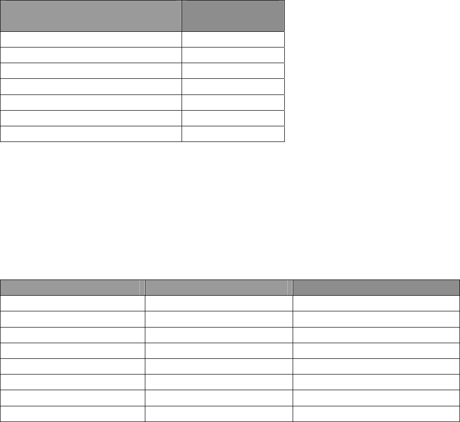
2.1 Charging the Battery
Plug the power adapter into the proper AC wall outlet; and insert the DC plug in the charger coup.
The Red LED flashes after it enters normal work. (Red LED lights per 4.5 seconds)
Insert the battery or the radio to be charged into the charger slot. Please turn off the radio before
insert it into the charger.
Make sure the battery is in good contact with the charger terminals. When the red indicator is
lighted, the charger begins to charge the battery.
After charging for about 3 hours, the red LED will turn OFF and the green LED will light
indicating the battery has been fully charged.
On the first charge, please leave the battery in that state of green indicator for 1~2 hours before
you remove it from the charger to achieve the best performance of the battery. Then you can
disconnect the power adapter from the AC outlet.
If the Red LED flashes quickly (0.2s on 0.2s off), this means the charging process stopped, This
could be because the charging temperature is too high or the battery has a problem, the charger
enters a protective state and no more charge is delivered to the battery. Please stop charging in
such situation and remove the battery from the charger.
Notice:
* The new battery is not fully charged in the factory, and needs to be fully charged when you use
the radio for the first time.
* The radio is supplied with a standard battery manufactured by the factory.
* When you charge the battery for the first time after purchasing or after a long time storage (over
2 months), you should repeat charging it several times to achieve the normal battery capacity.
* Do not recharge the battery after it has been fully charged or it is partially discharged, otherwise
it might affect the battery life or performance. Remove the battery from the charger after
charging is finished.
* If the radio enters low Battery warning state, please recharge the battery. Do not use the radio in
low power state, which will affect the battery life and performance.
Installing/Removing the Battery Pack
Installing/Removing the Battery Pack
To install the battery, please place it into the groove on the top of the radio chassis about 5mm
away from latch.
If the radio has the belt clip installed, you will have to press one side of the clip, to raise it and
slide the battery in proper position.
Press the battery with your fingers and push the battery until you hear a latch click, the battery is
now installed.
Removing the battery pack:
If you want to remove the battery from the radio, first press the battery latch located
on the bottom of the radio, and then press down to slide the battery about 5mm to release
the latch.
Notice:
* Do not short-circuit the battery terminals or dispose the battery in fire.
* Do not disassemble the battery case.
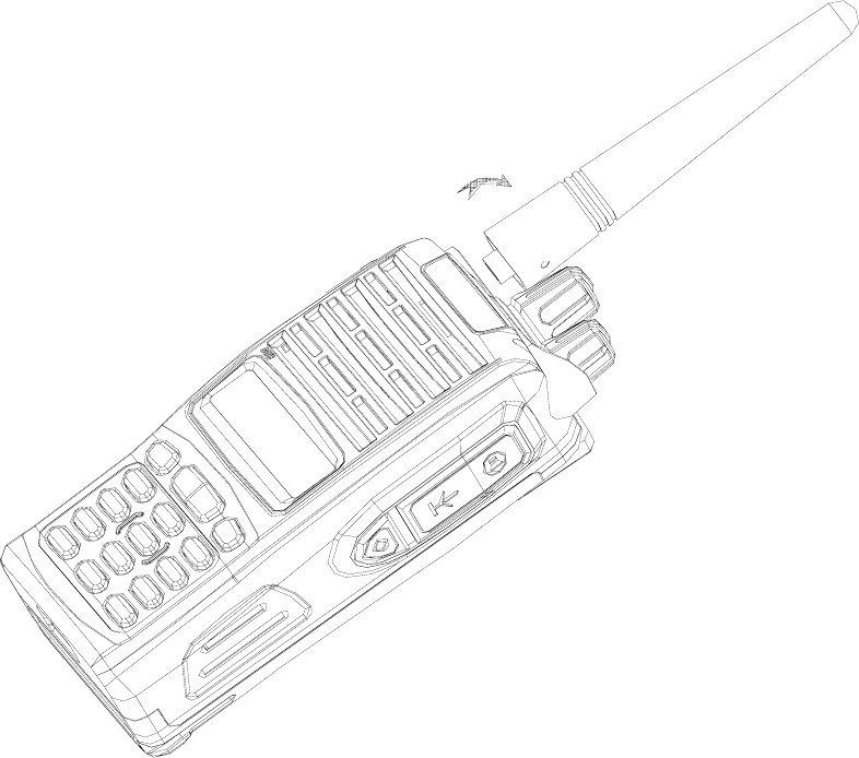
2.3 Installing the Antenna
Screw the antenna into the connector at the top of the radio by holding the bottom of the antenna
and turn it clockwise until secure.
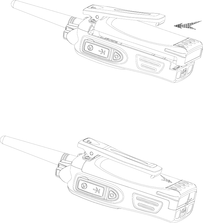
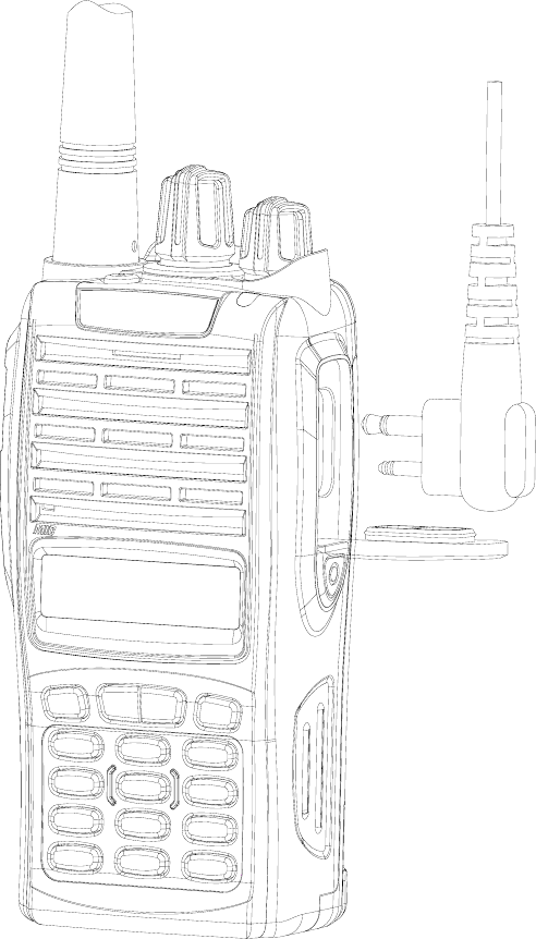
2.4 Install external speaker/MIC
Open the cover of the jack for external speaker/MIC, and then insert the plug of the external
speaker or microphone into the jack on the radio. When inserting the accessory plug, make sure it
is properly aligned ( straight) to avoid internal damage to the connector in the radio.
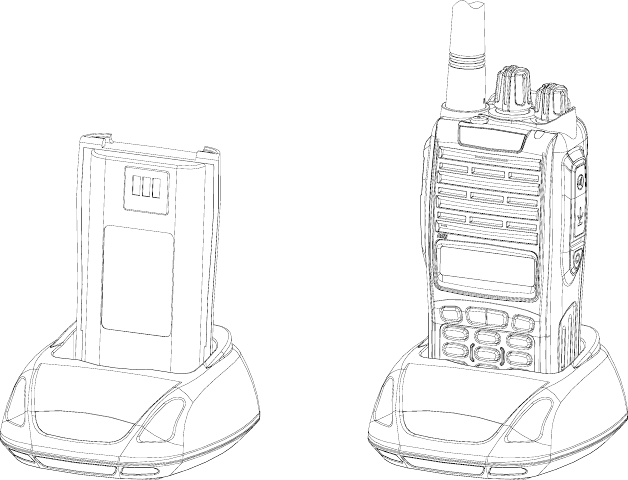
2.5 Installing/Removing the Belt Clip
Use the 2 screws (M2.5x8.0) supplied with the radio and fix these screws on the holes in the
radio clip and into the holes in the aluminum case. If you want to remove the clip from the radio,
just unscrew them, and remove the clip, you can put the screws back to make sure you do no loose
them.
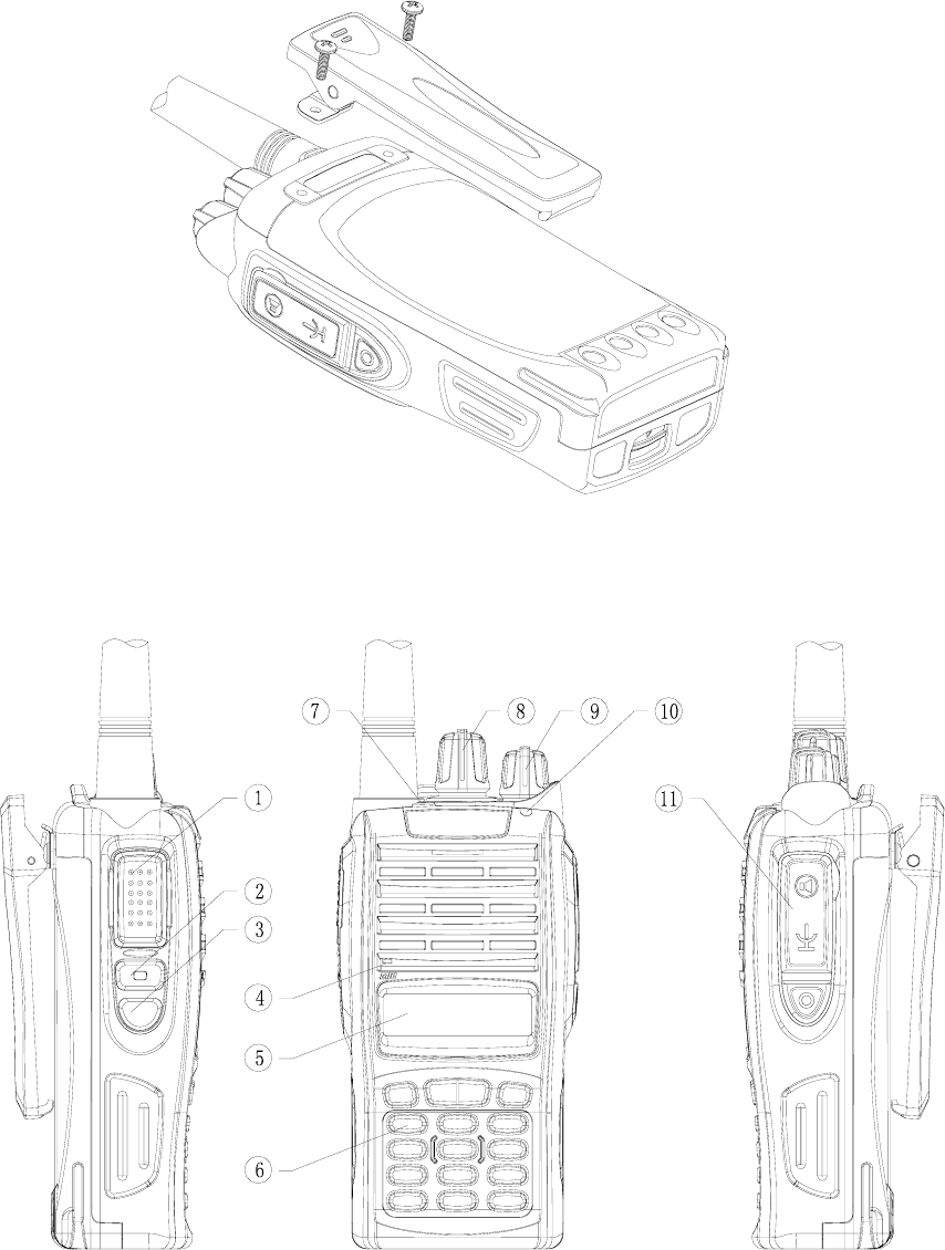
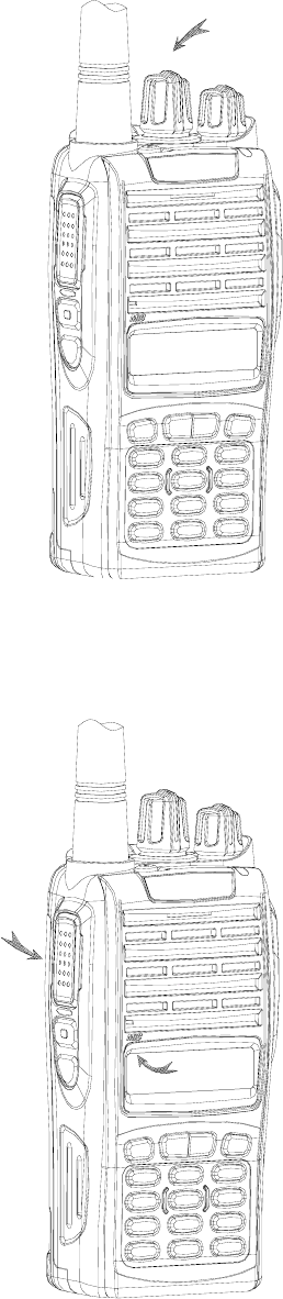
3、Radio Overview
① PTT ( PUSH-TO-TALK) Button
To make a call, press and hold the PTT button, then speak into the microphone in normal
voice. Release the PTT button to receive signals.
② Side Button 1 (Programmable Button)
③ Side Button 2(Programmable Button)
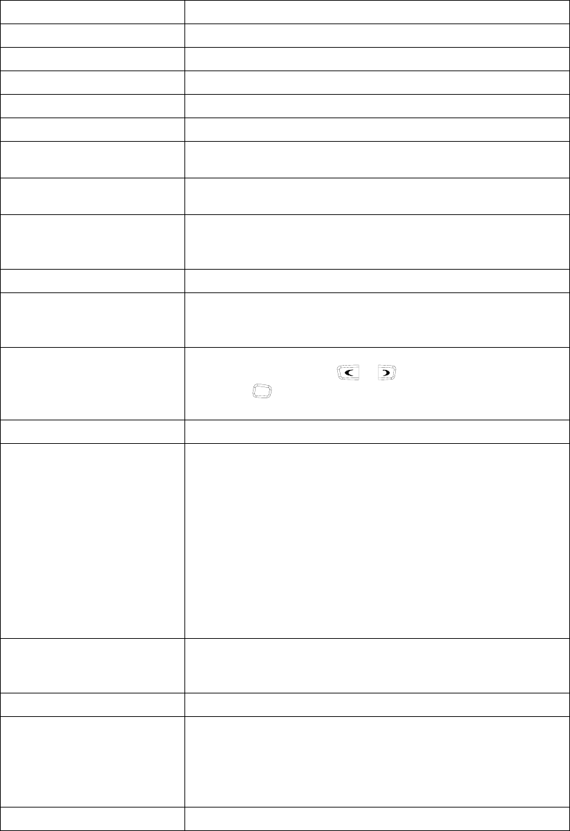
④ MIC Input
Please keep your mouth about 10 cm (3-4 inches) away from the microphone input to
achieve the best voice quality. If the distance is too far or too close to the radio, it will affect
the voice quality.
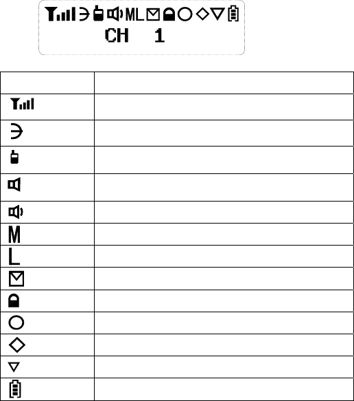
⑤ LCD
ICON Description
Received Signal Strength Indicator
Scan
Talk Around
Monitor
Squelch Open
TX Middle Power
TX Low Power
New Message
Key Locked
Select Staus
Programmable Icon
Scrambler
Battery Meter
⑥ Key Pad
⑦ Top Button (Programmable Button)
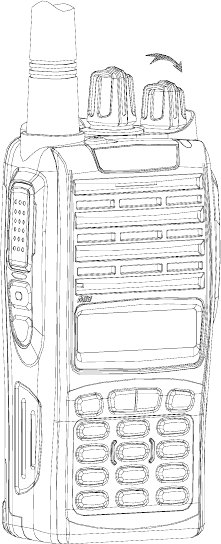
⑧ Channel Selector
Rotate to select channel 1~512.
⑨ Power/Volume Knob
Turn clockwise to switch on the radio.
Turn counterclockwise till a click is heard to switch off the radio.
Rotate to adjust the volume after turning on the radio.
⑩ LED Indicator
LED Indicator Status/Alert. Green LED lights when a carrier is detected in the current
channel. Red LED lights during transmission. Flashes orange when receiving 5-Tone
signaling or 2-Tone signaling or MDC signaling. Green LED flashes when scanning or Red
LED flashes when low battery.
⑪ Speaker/Microphone Jacks
Used to connect the optional speaker/microphone.
4、Basic Operations
1. Power on the radio
Turn on the radio by turning the Power/Volume switch clockwise till a click is heard, and you
will hear a Power up beep if the dealer has set it. The radio is now in Rx mode.
2. Adjust Volume:
Rotate the Power/Volume knob to adjust the volume with the monitor key pressed.
Turn clockwise to increase the volume and counterclockwise to decrease the volume.
3. Select a Channel:
Rotate the channel selector to the desired channel. When a signal is received, it will be heard
in the speaker.
4. Make a Call:
To make a call, press the PTT, and speak in normal voice and please keep your mouth about 10 cm
(3-4 inches) away from the microphone to achieve optimal voice quality.
5. Receive a Call:
Release the PTT button and adjust the volume at the proper position to receive calls.
The dealer can set CTCSS/DCS, 5-Tone or 2-Tone DTMF or MDC on your radio. On the
channels programmed with Selective Signaling, you will not hear calls except those from the
radios in the same group and sending the proper ID.
■ Programmable Button Function
The dealer can program the Side Button 1, Side Button 2 and the Top Button with the following
Optional functions:
Buttons Function Description
None No function
Channel Up Select the next channel
Channel Down Select the previous channel
Zone Up Select the next zone
Zone Down Select the previous zone
Display Channel Frequency Press this button and the LCD will show the frequency of the current
channel.
Display Channel Name Press this button and the LCD will show the name of the current
channel.
Display Mode Switch
Press this button and the LCD will show “Channel Number”,
“Channel Name”, “Zone Number, Zone Name” and “Channel
Frequency” alternately.
OST Change the setup of preset CTCSS/DCS for the current channel.
Power level Selection
Press this button to make selection among the high, medium and
low transmission power, and “H”, “M” and “L” will be shown on the
LCD to represent the current transmission power.
Squelch Level Selection
Press this button to enter the “Squelch Level Adjustment Mode”
first, and then press the / button to adjust the level.
Press the O button to save the selected squelch level and quit
this mode.
Key lock To toggle between locking/unlocking your radio’ keypad.
Scan
Scan
a) Press the button set as “Scan” to start or stop scanning. If
scan beep tone enabled, 4 high beeps will indicate entering
scanning state, or 4 low beeps indicate exiting scanning
state. If scan LED enabled, (the GREEN LED will blink
while scanning).
b) The working channel of the radio will revert to the defined
channels automatically when you press PTT button during
scanning.
Nuisance Delete
When one channel continually generated unwanted noise. this
allow you temporary remove the channel from the current active
scan.
Voice Companding Start/end the voice compression/expansion function.
Public Address
Start/end the public address function. Press this button and the
function will be activated. Press the PTT button and speak to the
microphone so that you can hear your voice through the external
speaker . Press this button once again and return to the normal
user mode.
Scrambler Enable or Disable voice scrambler function.

Home Channel Changes to the home channels.
Talk around Switch the radio between talk around and repeater mode.
VOX Selection Enable or disable the VOX function.
Monitor momentary/
Call Cancel
Hold this button to close CTCSS, DCS, 2Tone/DTMF signaling
according to the set data. Loosen this button to return to the normal
operation. Press this button in the selective call state to quit such a
state.
Monitor/Call Cancel
Press this button to trigger this function and the CTCSS, DCS,
2Tone/DTMF signaling will be closed, so you can receive the signal
that can't be heard in the normal operation. Press this button again
to return to the normal operation. Press this button in the selective
call state to quit such a state.
Squelch off momentary/
Call Cancel
Hold this button to open the squelch. loosen this button to return to
the normal operation. Press this button in the selective call state to
quit such a state.
Squelch off/Call Cancel
Press this button to open squelch, press it again to return to normal
operation. Press the button in the selective call state to quit such a
state
Emergency Alarm
When you press the top button set as “Emergency Call”, the
radio will enter emergency state, the radio can sound alarm
tone or transmit ID code or background tone to your partners or
the system, the detail setting is programmed by your dealer.
Cancel Emergency Call Press the top button set as “Cancel Emergency Call” to cancel
Emergency function.
Man-down
Press this key to enable or disable man-down function, which is
an optional function. If being in “man-down status” for a
setting time, the radio will sound pre-alert tones. If not being
set straight in another setting time, the radio will enter
“Emergency state.”
Radio Call Press this button and to enter the fast menu mode of “Radio Call”.
For detailed operation, see “Menu Operation”.
Call Button 1 Sends the DTMF/2Tone/5Tone code assigned to call 1 key.
Call Button 2 Sends the DTMF/2Tone/5Tone code assigned to call 2 key.
Call Button 3 Sends the DTMF/2Tone/5Tone code assigned to call 3 key.
Call Button 4 Sends the DTMF/2Tone/5Tone code assigned to call 4 key.
Menu Select /Enter To enter the menu mode or make menu selections.
Horn Alert Enables the Horn Alert
Lone worker
When the radio is set in lone work, it will sounds pre-alert
tones before the Lone Work time expires, and the user should
press any key on the radio within the Reset Time, indicating the
user is safe, otherwise, the radio will enter emergency state
automatically.
Scan List Edit Press this button and the radio will enter the fast menu mode for
scan list edit. For details, see “Menu Operation”.
GPS Information View Press this button and the radio will enter the menu mode of GPS
Information Menu.
VOX Level Selection
Press this button to enter the VOX Level Adjustment Mode”. Press
/ button to adjust VOX level. Press O button to save
the selected VOX level and quit this mode.
When pressing a Key, notice the different beeps you will hear
No beep, key pressed not acknowledge
one beep, feature enable
two beeps, feature disable
“Error” beep, key pressed invalid
5. Radio Call
5.1. Selective Call
5.1.1 Send Selective Call
A. Press “Menu Select/Enter” button to enter the menu mode.
B. Press / button until “RADIOCAL”.
C. Press O button to select “SEL CALL”.
D. Press / button until the required call list appears.
E. Press “PTT” button to send the selective call.
F. Press “PTT” button and speak to the microphone in normal voice. Please keep the
microphone about 3 to 4 cm far from your mouth. After speaking, please loosen the
“PTT”.
G. Press C button to return to the previous operation.
5.1.2 Receive Selective Call
Receiving a selective call, you will hear the alert tone and the LED indicator will blink
orange. Icon flashes and the caller’s ID or name displays.
Press PPT button for callback.
5.2 Call Alert
After the radio receives the call alert, the alert tone will sound and the orange indicator
flicker. icon flashes and the caller’s ID code or name shows until someone answers.
Press the “PTT” button for callback or other buttons for cancellation.
A. Press “Menu Selection/Enter” button to enter the menu mode.
B. Press / button until “RADIOCAL”.
C. Press O button to select “CALL ALT”.
D. Press / button until the required call list is showed.
E. Press “PTT” button to send the call.
F. After calling, press
C button to return the previous operation.
6. Select Zone
According to the setup of the communication network, the radio can be distributed to
different zones. Select the proper zone to realize communicating with the radio from a
different zone.
1. Select the zone through menu.
A Press the “Menu Selection/Enter” button to enter the menu mode.
B Press / button until “ZONE”.
C Press O button for selection.
D Press / button until the group name you require is appeared.
E Press O button for selection.
1 Select the group through “ZONE UP” or “ZONE DOWN” button.
7. Talkaround
In the communication network, you can expand communication range through the
repeater, but when the mobile radio is out of the communication range, you can connect
with other radio in the talkaround method. The talkaround function can be showed by .
1. Select the talk around by menu.
A. Press the “Menu Selection/Enter” button to enter the menu mode.
B. Press / button until “RPTRTALK”.
C. Press O button for selection.
D. Press / button until “REPEATE” or “TALKRND”.
E. Press O button for confirmation.
2. Switch the talkaround or repeater mode through “talkaround” button.
8. Utilities
The item can help you customize some setups of the radio.
The operating steps go as follows:
A. Press the “Menu Selection/Enter” button to enter the menu mode.
B. Press / button until “UTILITY”.
C. Press
O button for selection.
D. Press / button until the items you require are showed.
E. Press
O button for select. The radio will show the current setup.
F. Press / button to show all items that can be set with this item.
G. Press
O button to select this setup
H. Press
C button to return to the previous operation.
Change the setup items in the following table as per the previous steps.
Items Selectable Setups Functions
Squelch Level
"SQL LEV "
SQL 0 ~ 9 Change the squelch level of the radio.
Transmission Power
"PWR LEV "
"PWR LOW "
"PWR MID ",
"PWR HI "
Select transmission power among high,
medium and low levels.
VOX Level
"VOX LEV "
VOX 0 ~ 9 Change the VOX level of the radio.
Backlight
"BACK LED"
“BLED OFF"
"BLED ON "
"BL AUTO "
Select among such modes of backlight as
“turnoff”, “normal turn-on” or “auto”.
MCU software version …… Show the software version.
display
"SOFT VER"
Eg.“V1.1.00”
9. Scan
In order to receive the calls from many channels, the radio can be programmed to scan
these channels. At most there are 16 channels in each scan list. Each channel can use a
scan list together with others or alone.
9.1 Start/End Scan Function
You can press “SCAN” button directly or enable the scan through the menu.
When the scan function is started, icon and your revert channel will display .
1. Enter the scan state through menu mode.
A. Press the “Menu Selection/Enter” button to enter the menu mode.
B. Press / button until “SYS SCAN”.
C. Press O button for selection.
D. Press / button until “SCAN ON?” or “SCAN OF?”
E. Press O button for select.
2. Use the scan button.
A. Press “SCAN” button to activate the scan function.
B. Press “SCAN” button again to disable the scan function.
9.2 Nuisance Delete
If a channel continuously generates noise or interference, press the button to remove
this channel from the scan list temporarily.
Note: the priority channel can't be removed and the last one in the scan list, either.
9.3 Edit Scan List
9.3.1 Add or Delete the Channels in the Scan List
A. Press the “Menu Selection/Enter” button to enter the menu mode.
B. Press / button until “PROG LST”.
C. Press O button to select “SCAN LIST”.
D. Press / button until “ADD LST?” or DEL LST?”.
E. Press O button for selection.
F. Press / button until the channel you want to add or delete.
G. Press O button to complete operation you will see“CHNSAVE” (If you added a
channel)or“CHN DEL”.
H. Press C button to return to the previous operation.
9.3.2 Set Priority Channel
1. Press the “Menu Selection/Enter” button to enter the menu mode.
2. Press / button until “PROG LST”.
3. Press
O button to select “SCAN LIST”.
4. Press / button until “ED PRIO?”.
5. Press
O button for selection.
6. Press / button until “PRIO#1?” or “PRIO#2?”.
7. Press
O button to select the type of the required priority channel.
For example, in Step 7, the type of priority channel is “DES?”.
Press / button to select the required priority channel.
8. Press
O button to complete operation.
9. Press
C button to return to the previous operation.
10. OST
In a certain specific channel, you can revise the CTCSS/DCS encode/decode setup of
current channel.
The operating steps go as follows:
A. Press the “OST” button to enter the OST menu mode.
B. Press / button until the CTCSS/DCS encode/decode you want.
C. Press O button to select.
Note:
¾ When the OST backup function is enabled, the radio retains the OST code of
each channel even if the channel is changed or the radio is shut down
¾ In the OST state, P2“·”icon will display.
¾ Press “OST” button again to return to normal operation.
11. GPS Information View
If the radio starts the GPS function, you can view the current GPS information. The
specific operating steps go as follows:
A. Press “GPS Information View” button to enter the GPS information display mode.
B. Press / button until the items you require displays.
C. Press Obutton for selection.
D. Press / button for page up of the following content.
E. Press C button to return to the previous operation.
The specific content can be shown as follows:
1. Positioning star number: “STAR NUM”
2. Longitude “LONGITUD”
3. Latitude “LATITUDE”
4. Altitude “ALTITUDE”
5. Speed “SPEED”
6. Time “TIME”
■ VOX (Voice Operated Transmission)
VOX allows hands-free transmission on the radio when using the appropriate earphone/headset.
Two types of VOX are available: built-in and external.
If VOX has been set, when speaking voice reach the preset volume, VOX will activate the radio to
transmit automatically.
■ Radio Setting
TOT (Time-out Timer)
1) TOT dispatch time
The TOT Dispatch Time is the maximum period of time that the radio is allowed to transmit
continuously in normal dispatch mode. When the programmed time expires, the radio generates a
warning tone and stops transmitting. The range for the TOT Dispatch Time is from 5 seconds to
600 seconds in step of 5 seconds..
2) TOT Re-key
a) TOT re-key specifies the time when transmission is prohibited after the time-out timer is
activated.
b) During the time of transmitting prohibition, if you press the PTT button, warning tone sounds
and transmitting is prohibited.
3) TOT Pre-alert
a) Before the time-out timer stops transmitting, the radio sounds pre-alert tone.
b) After the alarm tone, if the transmitting time is longer than the preset time limit, the time-out
timer will be activated.
4) TOT Reset
a) TOT Reset is the delay time between releasing the PTT button and resetting the time-out
timer.
b) If the time of releasing the PTT button is shorter than the TOT Reset, the countdown of
transmitting prohibition will continue.
Battery Save
The dealer can program the battery save type.
If the battery save function has been set, 10 seconds after no signals being received or no
operations being conducted, the radio enters the battery save mode. It will exit the battery save
mode automatically after receiving signals or being conducted.
Battery Save Types: Short, Middle, Long and OFF.
Battery save function can increase battery active time.
Low Battery Warning
Low Battery warning tone sounds and RED LED flashes when the battery power goes below the
preset value and you need to recharge the battery. If the battery voltage is too low, transmission is
prohibited.
CTCSS/DCS
The dealer can set CTCSS/DCS on the radio channels to ignore calls on the same channel from
irrelevant radios.
If a channel has been set with CTCSS/DCS, the squelch will be activated only when it receives the
proper CTCSS/DCS signals. And only the radios set with the same CTCSS/DCS signaling as
those on yours can hear your call.
Note: Using a CTCSS/DCS channel doesn’t mean your calls are private. If the CTCSS/DCS tones
of other radios are identical with those on yours, they can hear your calls.
■ User Template
A user template includes PTT code-transmitting, encoding, decoding, Busy Channel Lockout, Call
1/2/3/4, RX squelch mode, TX conditions and decoding conditions, etc. Maximum 16 user
templates are available on this radio.
RX Squelch Mode
The dealer can set conditions under which the speaker will be activated from the following 4
options:
1) CTCSS/DCS and Audio Squelch: The speaker will be activated only when both CTCSS/DCS
and the selective signaling matched.
2) Audio Squelch: The speaker will be activated when the selective signaling matched.
3) CTCSS/DCS Squelch: The speaker will be activated when CTCSS/DCS matched.
4) Carrier Squelch: The speaker will be activated when carrier wave presents
Scan
When in scanning, the radio checks signals on each channel; it stops scanning and pauses on the
channel on which signals are detected until the signals disappear. If a delay time has been set
between the interval of signal disappearing and scanning restarting, the radio will
stay on that channel if it receives any signals during the delay time.
The operating channel of the radio will revert to the following channels automatically when you
press PTT button during scanning. The dealer can select one among the following six options.:
1) Start channel
When pressing PTT button, the radio will transmit from the channel described in the Start.
2) Selected channel
When pressing PTT button, the radio will transmit from the channel selected.
3) Last called
When pressing PTT button, the radio will transmit from the last channel that received a call.
4) Last used
When pressing PTT button during the scanning, the radio will transmit from the last channel you
used to talk.
C ) Priority Scan
During scanning, if the priority channel has been set on the radio, when the priority channel
receives signals the radio will automatically switch to the priority channel even the normal
channel is receiving signals at that time. And the radio will stay on the priority channel till the
signals disappear. The dealer can set the delay time between signal disappearing and continuing
scanning.
Temporarily Delete Noise Channel When scanning pauses on a channel, press and hold the button
Programmed as “Temporarily Delete Noise Channel” to delete this channel temporarily from the
scanning list.
Note: The priority channel cannot be deleted.
DTMF
The dealer can set DTMF signaling in the Personality Template. The Call Alert / Selective Call,
Message , ANI feature and so on can be set by your dealer.
5-Tone Signaling
The dealer can activate or inactivate this function by programming.
5-Tone has 9 encoding formats: CCIR1, CCIR2, ZVEI1, ZVEI2, SVEI3, EEA, EIA, USER
DEFINED 1, and USER DEFINED 2. The last tow formats are user defined.
1) 5-Tone Decode
The decoding template is 5-tone decoding. If the decoding template matches the encoding
template, decoding succeeds.
When receiving proper 5-tone signaling, squelch will be activated according to the “RX Squelch
Mode” defined by the user. You can receive the call and LED flashes orange.
After the radio decoding succeeds, the radio will work according to the decoding call response set
by the dealer.
2) 5-Tone Encode
Encoding template consists of at least one and at most three encoding sequences and each
decoding sequence can be set with 5-Tone, and DTMF. If it is set with 5-Tone, you need to
program its content.
If the PTT ID on the channel you select has been set with 5-Tone, 5-Tone signaling will be
transmitted when making a call.
Or transmit 5-Tone signal by pressing the Call 1/2/3/4 button,, which can be set by the dealer.
2-Tone Signaling
This function can be enabled or disabled by dealers through programming software.
2Tone has 4 systems; the single tone continuous time, such as first tone or second tone, could be
set by the dealer.
1) 2Tone decode
If the received 2 tone is same as the template chosen then it can decode successfully. After the
radio received the correct 2 tone signaling, according to the Receive squelch mode set by the user,
the squelch will be ON. Then, the radio can receive the call and the orange LED light flashes.
After decoding successfully, the radio can work according to the decode call response set by the

dealer.
2) 2Tone encode
The encoding template is set in the 2 tone call list. The details must be set if encoding is ON. The
radio transmits the 2 tone signaling when the programmed call button is pressed. (The side button
could be programmed as Call1/2/3/4). This function is programmed by the dealer.
MDC Signaling
This function can be enabled or disabled by the dealers through programming software.
MDC has 4 systems, in which different main ID, group ID, etc., could be set by the dealer.
1) MDC decode
The option MDC system can be set through the RX signaling system in the personal template. If
the received MDC code is same as the one set in the system, it can decode successfully. After the
radio received the correct MDC signaling, according to the Receive squelch mode set by the user,
the squelch will be ON. Then, the radio can receive the call and the orange LED light flashes.
2) MDC encode
If the PTT ID of the chosen channel is set as MDC, the MDC code will be transmitted when
calling.
■ Troubleshooting
No. Problems Solutions
1
The radio cannot be
switched on or no
display after switched
on.
z Battery pack may not be installed properly. Remove the battery pack
and install it again.
z Battery power may be insufficient. Recharge or replace the battery
pack.
2
The battery power
consume quickly after
charging.
z The battery life is finished; please replace it with a new battery pack.
3
Cannot talk to or hear
other members in your
group.
z The frequency or CTCSS/DCS signaling are not identical and please
reprogram it.
z Make sure the setting of the selective signaling 5-Tone in he RX
Squelch Mode is proper.
z Beyond the radio efficient communication range.
4
Other voices from
non-group members
are heard on the
channel.
z Change the CTCSS/DCS tone, and make sure change the tone on all
radios in your group.
z Please set 5-Tone selective signaling on the channel.
5 Communication range
is too small.
z Make sure the antenna is well connected.
z Make sure the antenna is the originally supplied one.
z Check if the battery power is in the normal state.
z Ask your local dealer to adjust the squelch level.
6 Unable to transmit.
z Make sure the PTT button has been pressed completely.
z Battery power may be insufficient. Recharge or replace the battery
pack.
z Transmitting frequency has not been set on the channel and the radio
has been remote killed.
7 Noise is too loud.
z Battery power may be insufficient. Recharge or replace the battery
pack.
z Beyond the efficient communication range.
■ Settings (by the Dealer)
Model: ____________ Serial No.: ___________
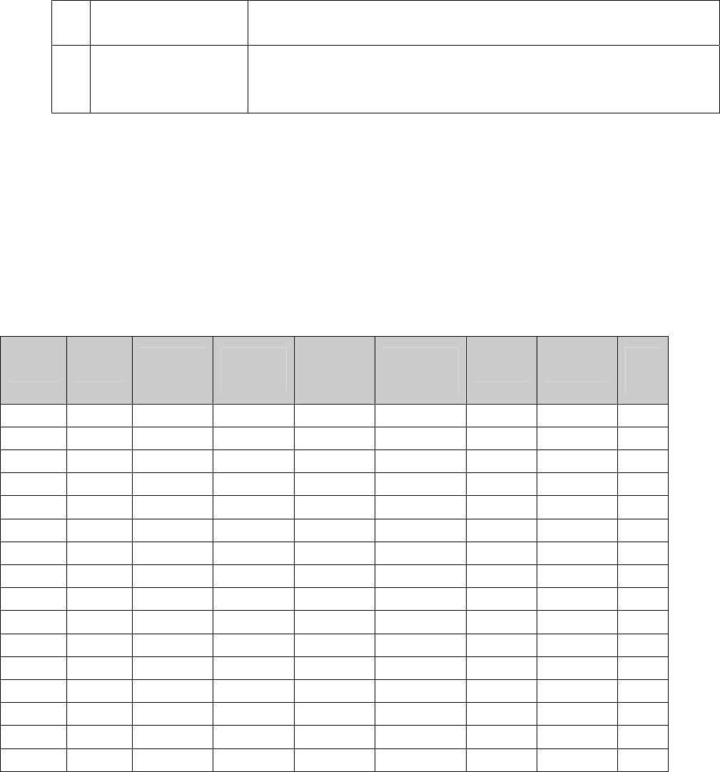
1) Channels List
Channel
Type Receiving
Frequency
Transmittin
g Frequency
CTCSS
/DCS
Decode
CTCSS
/DCS Encode Power Bandwidth Scan
List
1
2
3
4
5
6
7
8
9
10
11
12
13
14
15
16
2) Optional Functions
Time-out Time (TOT)
5-600s
Squelch Level
0-9
Voice Annunciation
ON □ OFF □
Battery Save
OFF □ Short □

Middle □ Long □
3) Auxiliary Function Button Settings
Note: