CRAFTSMAN Jointer/Planer Manual L0304248
User Manual: CRAFTSMAN CRAFTSMAN Jointer/Planer Manual CRAFTSMAN Jointer/Planer Owner's Manual, CRAFTSMAN Jointer/Planer installation guides
Open the PDF directly: View PDF ![]() .
.
Page Count: 16

Operator's Manual
CRRFTSMRNo
6V_"
Bench Top
JOINTERJPLANER
Model No.
351,286281
Colovos
CAUTION: Read and follow
all Safety Rules and Operating
Instructions before First Use
of this Product.
Sears Canada Inc., Toronto, Ontario M5B 2B8
2602.03 Draft (04/11/01 )
Warranty .................................. 2
Safety Rules .............................. 2-3
Unpacking ................................. 3
Assembly ................................. 3
Installation ............................... 4-5
Operetlon ................................ 5-9
Maintenance ............................ 9-10
Troubleshooting ............................ 11
Parts Illustration and List .................. 13-15
FULL TWO YEAR WARRANTY ON
CRAFTSMAN 6'I." JOINTER/PLANER
If within two full years from the date of purcllese, this
Craftsman Jolnterlplener falls due to adefect in matedsl
or workmanship, Sears w_LIrepair it free of charge.
Warranty service is available by contacting Sears. This
warranty is in addition to any statutory warranty.
If this Jolnter/planer is used for commercial purposes,
this warranty applies for only g0 days from t_a date of
purchase.
Sears Canada, thc., Toronto, Ontario MSB 2B8
WARNING: For your own safety, read all of the rules
and precautions before operating tool.
CAUTION: Always follow proper operating procedures
as defined in this manual even if you are familiar with
use of this or similar tools. Remember that being care-
less for even a fraction of a second can result In severe
personal injury.
BE PREPARED FOR JOB
• Wear proper apparel. Do not wear loose clothing,
gloves, necldles, rings, braceletS or other Jeweify
which may get caught In moving parts of machine.
•Wear protective hair covering to contain long hair.
•Wear safety shoes with non-slip soles.
• Wear safety glasses complying with United States
ANSI Z87.1. Everyday glasses have only impact
resistant lenses. They are NOT safety glasses.
•Wear face mask or dust mask if operation is dusty.
•Be alert and think clearly. Never operate power tools
when tired, intoxicated or when taking medications
that cause drowsiness.
PREPARE WORK AREA FOR JOB
•Keepworkarea clean, Clutteredwork areas invite
accidents.
•Do not use powertools]n dangerousenvironments.
•Do not use power tools in damp or wet locations. Do
not expose power tools to rein.
• Work area should be properly lighted.
•Proper electrical recepta_e should be avai)aPle for
tool.Three prong plug should be plugged directly
Into proper_ygrounded, three-prong receptacle.
oExtension cords should have a grounding prong and
the three wires of the extension cord should be of
the correct gauge.
*Keep visitors at a safe distance frorn work area.
•Keep children out of workplace. Make workshop child-
proof. Use padlocks, master switches or remove switch
keysto prevent any unintentional use of power tools.
TOOL SHOULD BE MAINTAINED
•Always unplug toolprior to inspection.
•Consult manual for specific maintaining and adjust-
Ing procedures.
•Keep tool lubricated and clean for safest operation,
•Remove adjusting feoJs. Form habit of checking to
see that adjusting tools are removed before sw{teh-
ing machine on.
•Keep all parts in working order. Check to determine
that the guard or other parts will operate properly
and perform their intended function,
•Check for damaged parts. Check for alignment of
moving parts, binding, breakage, mounting and any
other condition that may affect a tool's operation.
o A guard or other pa_ that is d_'nagsd sh_d be
properly repaired or replaced. Do not perform
makeshift mpalm. (Use parts list provided to order
replacement parts.)
KNOW HOWTO USE TOOL
=Use right tool for job. Do not force tool or attachment
to do a job for which it was not designed.
•Disconnect too) when changing b}sdes.
•Avoid accidental start-up, Make sure that the switch
is in the OFF position before plugging in.
•Do not force tool. it will work most efficiently a_ the
rate for which it was designed.
•Keep hands away from moving parts and cutting
sul'_ces.
•Never leave toot running unattended. Turn the power
off and do not leave tool until it comes to a complete
stop.
•Do not overreach. Keep proper footing and balance.
•Never stand on tool. Serious injury could occur iftool is
tipped or if blade is unintentionallycontacted.
•Know your tool. Learn the tool's operation, applica-
tion and specific limitations.
• Use recommended accessories (refer to page 15).
Use of improper accessories may cause risk of
injury to persons.
2
• Handle workpiece correctly. Protact hands from pos-
sible injury.
• Turn machine off if itjams. Blade jams when It digs
too deeply into workpiece. (Motor force keeps it
stuck in the work.I
• Always keep drive, cutterhesd and blade guards in
place and io proper operating condition.
•Feed work into blade or cutter against direction of
rotation.
CAUTION: Think safety! Safety is a combination of
operator common sense and atar_ess at all times
when tool is being used.
WARNING: Do not attempt to operate tool until It Is
completely essembled according to the instructions.
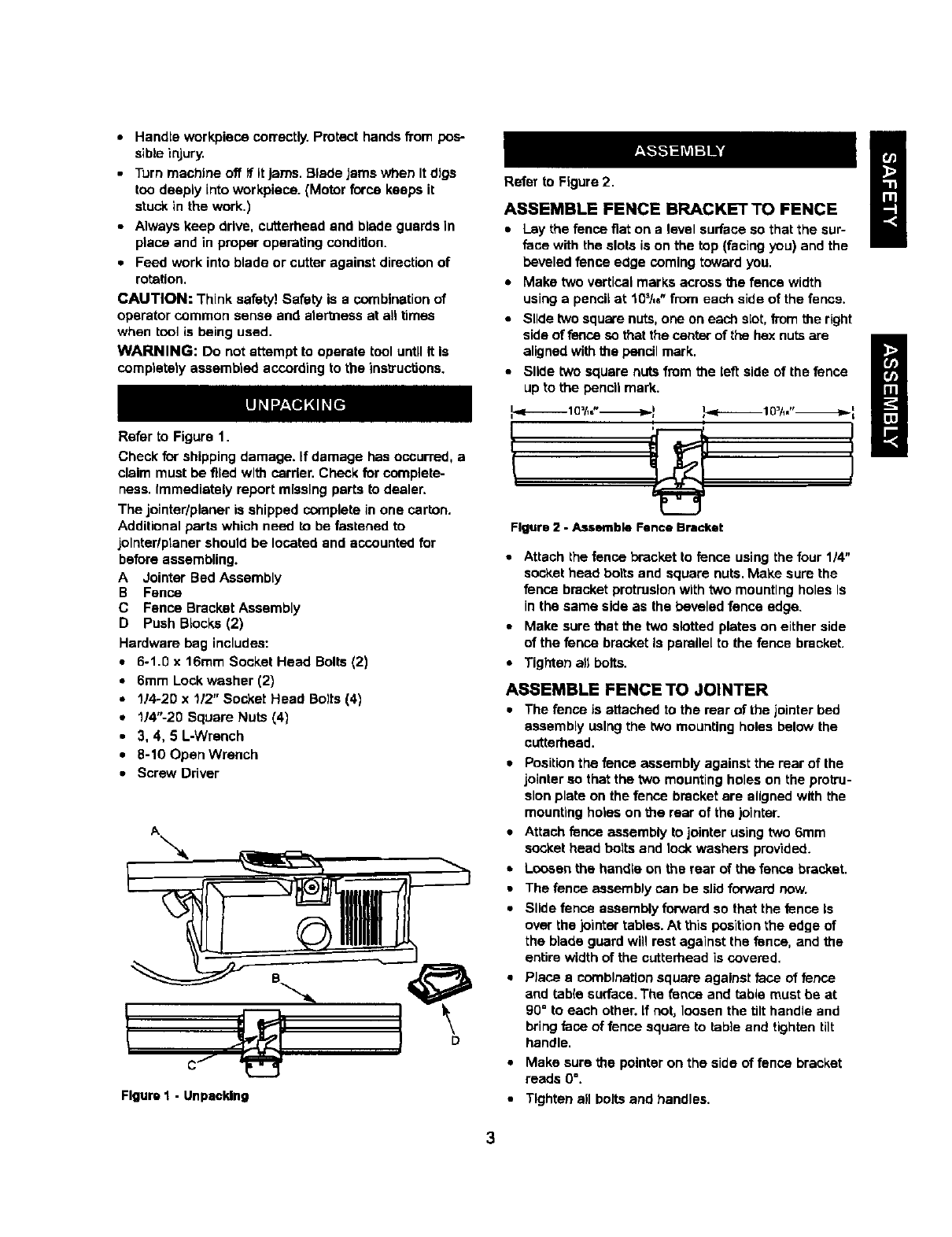
Refer to Figure 1.
Check for shipping damage. If damage has occurred, a
claim must be filed with carder. Check for complete-
ness. Immadtately report missing parts to dealer.
The jointer/planer is shipped complete in one carton.
Additional parts which need to be fastened to
jolnterlptaner should be located end accounted for
before assembling.
A Jointer Bed Assembly
B Fence
C Fence Bracket Assembly
D Push Blocks (2)
Hardware bag includes:
•6-1.0 x 16ram Socket Head Bolts (2)
•6mm Lock washer (2)
•1/4-20 x 1/2" Socket Head Bo)ts (4)
•1/4"-20 Square Nuts (4)
•3, 4, 5 L-Wrench
•8-10 Open Wrench
•Screw Driver
Figure I - Unpacking
Refer to Figure 2.
ASSEMBLE FENCE BRACKET TO FENCE
•Lay the fence fiat on a level surface so that the sur-
face with the slots is on the top (facing you) and the
beveled fence edge coming toward you.
•Make two vertical marks across the fence width
using a penci_at t0_/,e"from each side of the fence.
•Slide two square nuts, one on each slot, from the right
side of fence so that the center of the hex nuts are
aligned with the pencil mark.
•Slide two square nuts from the left side of the fence
up to the pencil mark.
Figure 2 - Assemble Fence Bracket
•Attach the fence bracket to fence using the four 1/4"
socket head bolts and square nuts. Make sure the
fence bracket protrusion with two mounting holes Is
in the same side as the beveled fence edge.
•Make sure that the two slotted plates on either side
of the fence bracket is parallel to the fence bracket.
• Tighten all bolts.
ASSEMBLE FENCETO JOINTER
•The fenceis attachedto the rear of the jointerbed
assemblyusingthe twomounting holesbelowthe
cutterhead.
•Position the fence assembly against the mar of the
jointer so that the two mounting holes on the protru-
sion plate on the fence bracket are aligned with the
mounting holes on the rear of the )ointer.
•Attach fence assembly to jointer using two 6mm
socket head bolts and lock washers provided.
•Loosen the handle on the rear of the fence bracket.
•The fence assembly can be slid forward now.
•Slide fence assembly forward so that the fence Is
over the jointar tables. At this position the edge of
the blade guard will rest against the fence, and the
entire width of the cutterhead is covered.
PJace a combination square against face of fence
and tab(e surface. The fence and table must be at
90=to each other, if not, loosen the tilt handle and
bring face of fence square to table and tighten tilt
handle.
Make sure the pointer on the side of fence bracket
reads O'.
Tighten all bolts and handles.
TheJolnter/pienerweighsapproximately30Ibs. when
completely assembled. The Jolnter/plener must be
installed In a piece with ample IlghUng and correct
power supply. To Install Jolntar/planter:
•Make sure there is plenty of room for moving the
workplace through the entire cut. There must be
enough room that neither the operators nor the
bystanders will have to stand In line with the wood
while using the tool.
•Jointer/planer can be installed on work using bolts,
lock washers and hex nuts (not supplied) or using
wood screws (not supplied).
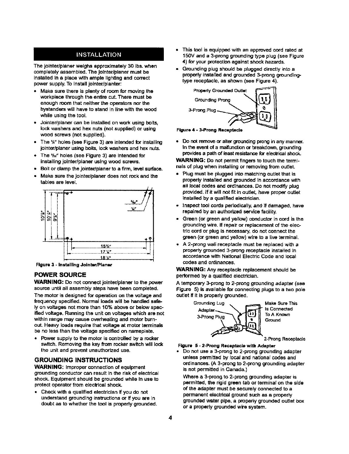
•The %" holes (see Figure 3) are intended for installing
jointer/planer using boils, lock washers and hex nuts.
•The %="holes (see Figure 3) are Intended for
installing jointer/planer using wood screws.
•Bolt or clamp the iointedplaner to a firm, levelsurface.
•Make sure the jointer/planer does not rock and the
tables are level.
•-|-._:_===:r.$,
,'e-= O) I
_1 .t...:t:::=
/
,,T
I I "15_A"
i_ la_h"
Figure 3 -InmtalllngJointar/Planar
POWER SOURCE
WARNING: Do not connect jointer/pianer to the power
source until all assembly steps have been completed.
The motor is designed for operation on the voltage and
frequency specified. Normal loads will be handled safe-
ly on voltages not more than 10% above or below spec-
ified voltage. Running the unit on voltages which are not
within range may cause overheating and motor burn-
out, Heavy loads require that voltage at motor terminals
be no less than the voltage specified on nameplate,
•Power supply to the motor is controlled by a rocker
switch. Removing the key from rocker switch will lock
the unit and prevent unauthorized use,
GROUNDING INSTRUCTIONS
WARNING: Improper connection of equipment
grounding conductor can result In the risk of electrical
shock. Equipment should be grounded while In use to
protect operator from electrical shock.
•Check with aqualified electrician if you do not
understand grounding Ins_'uctlons or if you are In
doubt as to whether the tool is properly grounded.
4
•This tool is equipped with an approved cord rated at
150V and a 3-prong grounding type plug (see Figure
4) for your protection against shock hazards.
•Grounding plug should be plugged directly into a
properly installed and grounded 3-prong grounding-
type receptacle, as shown (see Figure 4).
Properly Grounded Outlet
Grounding Pr_ _
Plu -
3-Prong g__
Figure 4 -3.Prong Receptacle
•Do not remove or alter grounding prong in any manner.
In the event of a maitunotlonor breakdown, grounding
provides a path of least resistance for efec_ical shock.
WARNING: Do not permit fingers to touch the termi-
nals of plug when installing or removing from outlet.
•Plug must be plugged into matching outlet that is
properly Installed and grounded In accordance with
a!l local codes end ordinances. Do not modify plug
provided. If it will not/_t in outlet, have proper outlet
installed by a qualified eLsctdcian.
• Inspect tool cords ber)odlca)Iy, and )f damaged, have
repaired by an authorized service facility.
•Green (or green and yellow) conductor in cord is the
grounding wire. It repair or replacement of the elec-
tric cord or plug Is necessary, do not connect the
green (or green and yellow) wire to a live terminal
•A 2-prong wall receptacle must be replaced with a
properly grounded 3-prong receptacle installed In
accordance with National Electric Code and local
codes and ordinances.
WARNING: Any receptacle replacement should be
performed by a quailed electrician.
A temporary 3-prong to 2-prong grounding adapter (see
Figure 5) is available for connecting plugs to a two pole
outlet if It is properly grounded.
GroundingLug _ _ Make SureThis
Adapter_'_'_ Is Connected
3.Prong_ ToA Known
Ground
2-Prong Receptacle
Figure 5 - 2-Prong Receptacle with Adapter
•DO not use a 3-prong to 2-prong grounding adapter
unlass permitted by focal and national codes and
ordinances. (A 3-prong to 2-prong grounding adapter
is not permitted in Canada.)
Where a3-prong to 2-prong grounding adapbsr is
permitted, the rigid green tab or terminal on the side
of the adapter must be securely connected to a
permanent electrical ground such as e properly
gmunded water pipe, a properly grounded outlet box
or a properly grounded wire system.
•Many cover plate screws, water pipes and outlet
boxes are not properly grounded. To ensure proper
ground, grounding means must be tested by a quali-
fied electrician.
EXTENSION CORDS
•The use of any extension cord wJlJcause some drop
In voltage and loss of power.
• Wires of the extension cord must be of sufficient size
to carry the current and maintain adequate voltage.
•Use the table to determine the minimum wire size
(A.W.G._ extension cord.
•Use only 3-wire extension cords having 3-.prong
grounding type plugs and 3-pele receptacles which
accept the tool plug.
•If the extension cord is worn, cut or damaged in any
way, replace it immediately.
EXTENSION CORD LENGTH
Wire Size A.W.G.
Up to 50 ft................................ 16
50-100 ft.................................. 14
NOTE'. Using extension cords over 100 ft. long Is not
recommended.
MOTOR
Jointer/pianer is supplied with a 1% HP (max devel-
oped) motor.
The 120 Volt AC universal motor has the following
specifications:
Horsepower (Maximum Developed) ............. l_h
Voltage ................................. 120
Amps ................................... 10
Hertz .................................... 60
Phase ................................ Single
RPM .................................. 8000
ELECTRICAL CONNECTIONS
WARNING: Make sure unit is turned off and discon-
nected from power source before inspecting any widng.
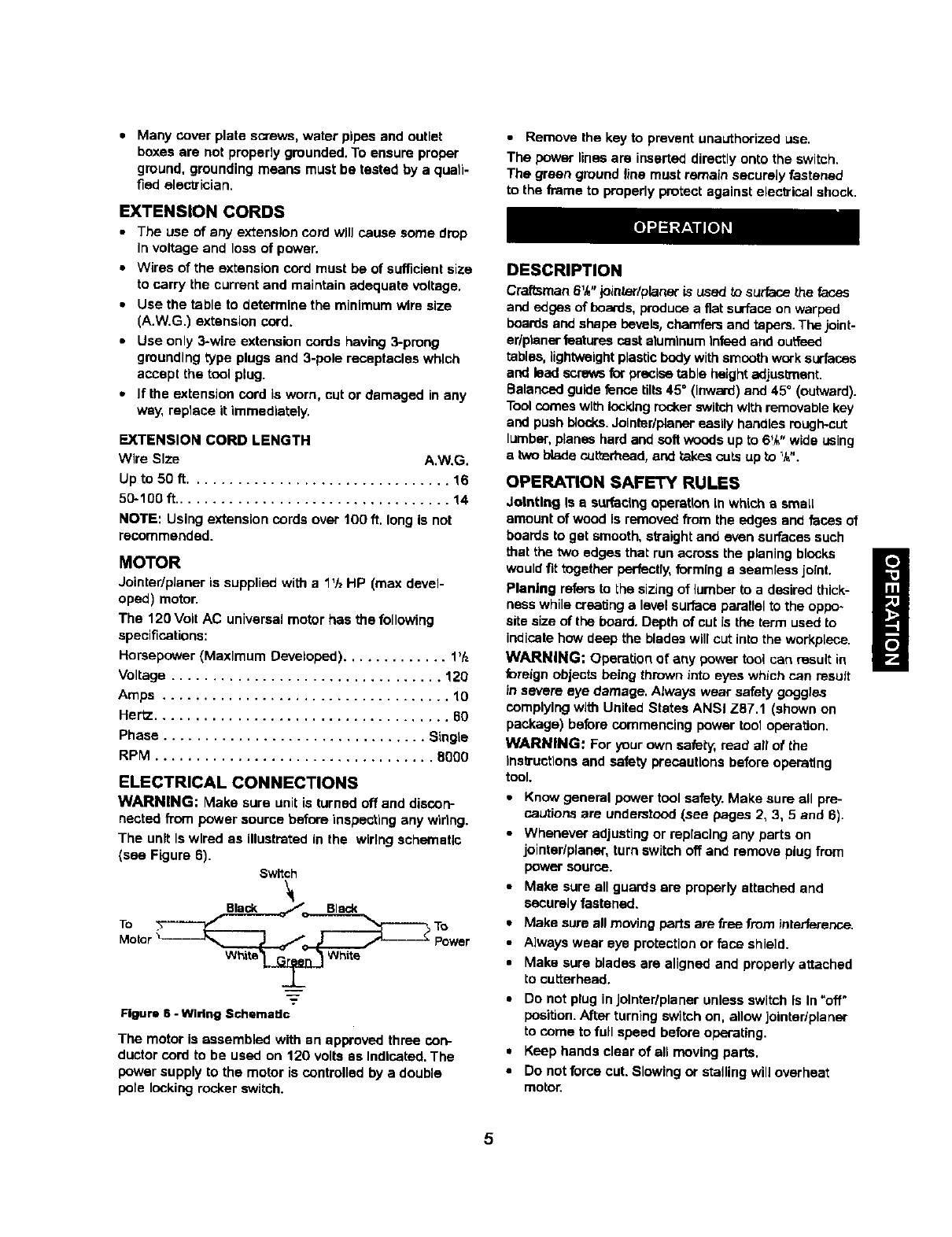
The unit Iswired as illustrated in the wiring schematic
(see Figure 6). Switch
Whi_l _ White
Figure 6 -Wiring SchemaUc
The motor is assembled with an approved three con-
ductor cord to be used on 120 volts as Indicated. The
power supply to the motor is controlled by a double
pole locking rocker switch.
•Remove the key to prevent unauthorized use.
The power lines are inserted directly onto the switch.
The green ground line must remain securely fastened
to the frame to properly protect against elecVical shock.
DESCRIPTION
Craftsman 6%" jointer/planer is used to s_Jrfacethe faces
and edges of boards, produce a fiat surface on warped
boards and shape bevels, chamfers and tapers. The joint-
er/ptaner features cast aluminum iofeed and ouffeed
tables, lightweightplastic body withsmooth work surfaces
and lead screws for precise table height adjustment.
Balanced guide fence tilts 45 °(Inw_d) and 45° (outward).
Tool comes wlt_ iockJng ro_er switch with removable key
and push blocks.Jointer/placer easily handles rough-cut
lumber,planes hard and soft woods up to 6_ "wide using
a two blade cuttorhead, and takes cuts up to %".
OPERATION SAFETY RULES
dothtlng Is a surfeclng operatLonin which a smaLL
amount of wood is removed from the edges and feces of
boards to get smooth, straight and even surfaces such
that the two edges that run across the planing blocks
would fit together perfectly, forming a seamless joint.
Planing refers to the sizing of lumber to a desired thick-
hess while creating alevel surface parallel to the oppo-
site size of the board. Depth of cut is the term used to
iedlcete how deep the blades will cut into the workplece.
WARNING: Operation of any power tool Can result in
foreign objects being thrown into eyes which can result
in severe eye damage. Always wear safety goggles
cemplylng with United States ANSi Z87.1 (shown on
package) before commencing power tool operation.
WARNING: For your own safety,,read art of _he
insb'uctlonsand safety precautions before operating
tool.
•Know general power tool safety. Make sure all pre-
cautions are understood (see pages 2, 3, 5 and 6).
•Whenever adjusting or replacing any parts on
jointer/planer, turn switch off and remove plug from
power source.
•Make sure all guards ere properly attached and
securely fastened.
•Make sure all moving parts are free from interference.
•Always wear eye protection or face shield.
• Make sure blades are aligned and properly attached
to cutterhead.
•Do not plug inJolnter/planer unless switch is in -off -
position. After turning switch on, allow jointer/planer
to come to full speed before operating.
•Keep hands clear of all moving parts.
•Do not force cut. Slowing or stalling will overheat
motor.
5
• Use quality lumber. Blades last longer and cuts are
smoother with good quality wood.
•Do not perform jointing/planing operations on materi-
al shorter than 8%", narrower than _/4",or !ess than
I/_,,thick
•Never make jointing cut deeper than 'k".
•Always keep cutterhead and blade guards in proper
working condition.
•Maintain the proper relationships of infeed and out-
feed table surfaces and cutterhead blade path.
•Do not back the work toward the Infeed table,
•Support the workplace adequately at all times during
operation; maintain control of the workplace.
•Use hold-down/push blocks for jolntlng material nar-
rower than 3" or planing material thinner than 3".
•Take precautions against kickback. Do not permit any-
one to stand or cross in line of cotterbead's rotation.
Kickback or thrown debris will travel In this direction.
•Turn switch offand disconnect power whenever
jointer/planer is not in use.
•Replace or sharpen blades as they become damaged
or dull.
• Do not attempt to perform an abnormal or little used
operation without study and the use of adequate hold-
down/push blocks, jigs, fixtures, stops and the like.
•Keep jointer/planer maintained. Follow maintenance
instructions (see pages g-lO).
DEPTH OF CUT
Refer to Figure 7.
The depth of cut is adjusted by the relative positioning
of the infeed table with respect to the cutterhead. Infeed
table can be raised or lowered using the handwheel.
Turning the handwheel counterclockwise will lower the
infeed table causing more wood to be removed from
workplece. Turning the handwhool clockwise will raise
the Infeed table causing less wood to be removed from
workpleca.
Do not make jointing or planing cuts deeper than V#.
[nfeed Table
Depth of Cut
Hand Knob
Figure 7 - Depth of Cut
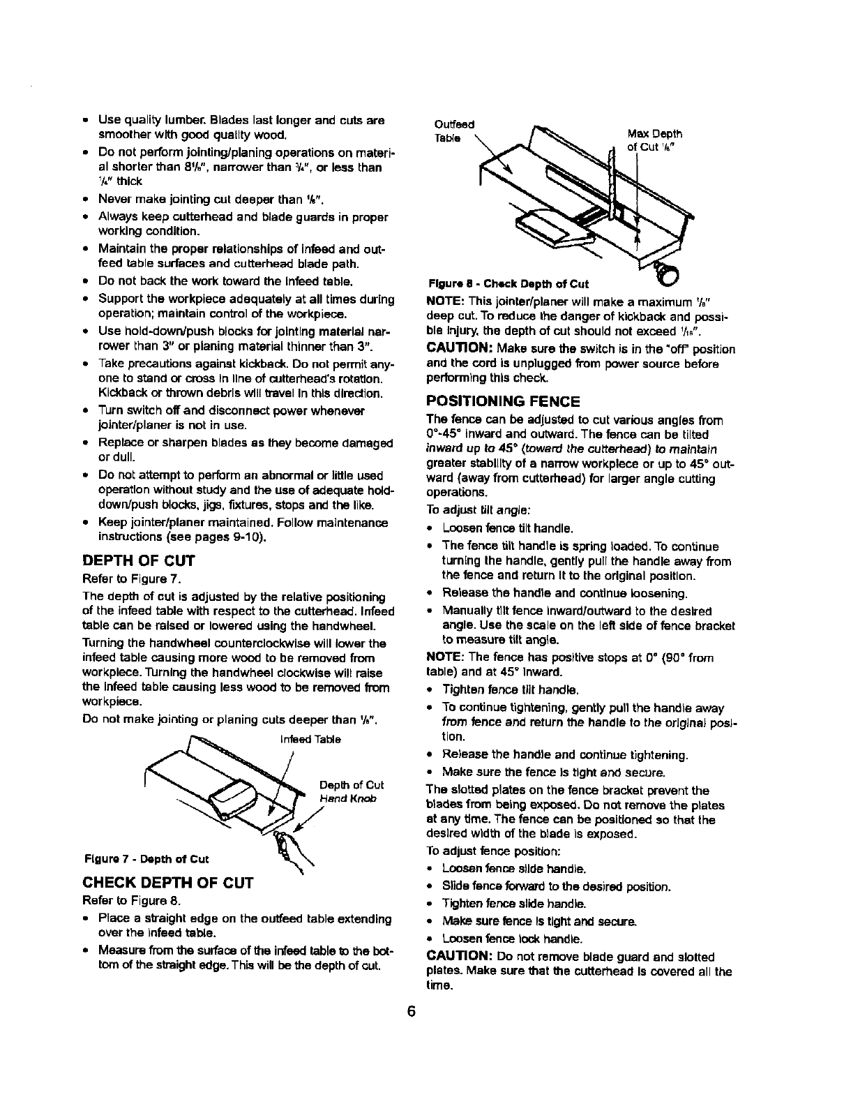
CHECK DEPTH OF CUT
Refer to Figure 8.
•Place a straight edge on the ouffeed table extending
over the Infeed table.
•Measure from the surface of the infsed table to the bet-
tom of the straight edge. This will be the depth of cut.
Outfeed
Table Max Depth
of Cut _/_"
FIgura e - Check Depth of Cut
NOTE: This jointar/planer willmake a maximum %"
deep cut. To reduce the danger of kickback and possi-
ble injury, the depth of cut should not exceed _/_".
CAUTION: Make sure the switch is in the "off positJon
and the cord is unplugged from power source before
perform)rig this check.
POSITIONING FENCE
The fence can be adjusted to cut various angles from
0°-45 °inward and outward. The fence can be tilted
idward up to 45" (toward the cutterhead) to maintain
greater stability of a narrow workplece or up to 45°out-
ward (away from cutterhead) for larger angle cutting
operations.
To adjust tilt angle:
•Loosen fence tilthandle.
•The fence tilt handle is spring loaded. To continue
turning the handle, gently pull the handle away from
the fence and return It to the odglnal position.
•Release the handle and continue loosening.
• Manually tilt fence Inward/outward to the desired
angle. Use the scale on the left side offence bracket
to measure tilt angle.
NOTE: The fence has positive stops at 0 °(g0°from
table) and at 45" Inward.
•Tighten fence tilt handle.
•To continue tightening, gently pull the handle away
from fence and return the handle to the original posi-
tion.
•Re)ease the handle and continue tightening.
•Make sure the fence )s tight and secure.
The slotted plates on the fence bracket prevent the
btadas from being exposed. Do not remove the ptatas
at any time. The fence can be positioned so that the
desired width of the blade is exposed.
To adjust fence position:
•Loosen fence slide hand)e.
•S)ide fence forward to the desired position.
•Tighten tense slide beadle.
•Make sure fence Is tight and secure,
•Loosen fence rock handle.
CAUTION: Do not remove blade guard and slotted
plates. Make sure that the cutterhead Is covered all the
time.
6
CAUTION: Do not slide fence away from the jointer
body. All sides of the cutterhead must be covered all the
time.
BLADE GUARD
The blade guard provides protection over the cuttar-
head. It must always be in place and function properly.
Check the guard to make sure it functions properly. To
check:
•Pass a V*"thick piece of wood over the cutter'head
between the guard and the fence. The guard will
spread and leave way for the wood piece to pass.
The guard must return to the original position auto-
matically when the wood piece is removed.
• Open the blade guard all the way until It stops, and
release it several times. It should always return to its
original position by spring action.
CAUTION: If the blade guard fails to operate properly,
the spring must be replaced or adjusted.
•To replace spring, contact your nearest Rears store
or service center.
=To adjust or to assemble spring see "Adjus'dngBlade
Guard", page 9.
ADJUSTING BLADE HEIGHT
Refer to Figures 9 and 10,
CAUTION: Make sure the switch is in the "OFF" posi-
tion and cord is unplugged before proceeding with
checking blades.
The blades have been adjusted at the factory to assure
proper operation and should require no adjusb'nent,
However, shipping and handling may have caused rues-
alignment. For accurate cutting, the blades must be
0.003" higher than the outfeed table when positioned at
the highest point. To check blade height:
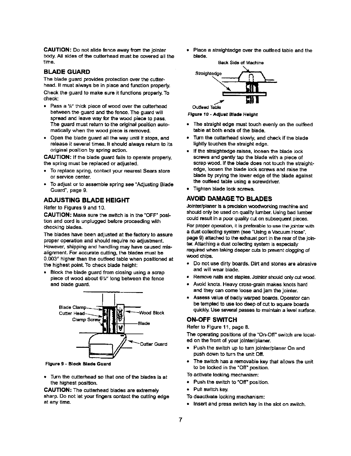
•Block the blade guard from closing using a scrap
piece of wood about 6V_"long between the fence
and blade guard.
Blade Clamp II
Cutter H:mad__Wad°de°_e Bl°ck
..__r"_ Cuttar Guard
Figure g -Block Blade Guard
• Turn the cutterhead so that one of the blades is at
the highest position.
CAUTION: The cuttarhead blades are extremely
sharp. Do not let your fingers contact the cutting edge
at any time.
•Place a straightedge over the outfeed table and the
blade.
BackSide of Machine
Straightedge /_L_"_
t I
GIll
Outfeed Table
Figure 10- Adjust Blade Height
•The straight edge must touch evenly on the outfeed
table at both ends of the blade.
•Turn the cuttarhead slowly, and check if the blade
lightly touches the straight edge.
•If the straightedge raises, loosen the blade lock
screws and gently tap the blade with a piece of
scrap wood. If the blade does not touch the straight-
edge, loosen the blade lock screws and raise the
blade by prying the lower edge of the blade against
the outfeed table using a screwdriver.
•Tighten blade lock screws.
AVOID DAMAGE TO BLADES
3oW_arlpLaneris aprecLsion_ing mechlne and
should only be used on quality lumber.Using bad lumber
could resultin a poor qualitycut on subsequent pieces.
For proper operation, itis preferable to use the jblnter with
adust collectingsystem (see "Using a Vacuum Hose",
page 9) aL'tachadto the exhaust port inthe rear of the join-
tel'.Attachinga dust collecting system is especially
required when taking deeper cuts io prevent clogging of
wood chll_.
•DO not use dirty boards. Dirt and stones are abrasive
and will wear blade.
,, Remove narisand staples. Jothtershou_ onty cut wood.
•Avoid knots. Heavy cross-grain makes knots hard
and they can come toose and jam the jointar.
• Assess value of badly warped boards. Operator can
be tempted to usa too deep of cut tu square boards
quickly.Use several passes to maintain a levelsurface.
ON-OFF SWITCH
Refer to Figure 11, page 8.
The operating positions of the "On-Off" switch are locat-
ed on the front of your jointar/planer.
• Push the switch up to turn jointar/planer On and
push down to turn the unit Off.
•The switch has a removabJa kay that alJowsthe unit
to be locked in the "Off" position.
To activate locking mechanism:
•Push the switch to'Off" position.
•Puff switch key.
To deactivate locking mechanism:
•Insert and press switch key in the slot on switch.
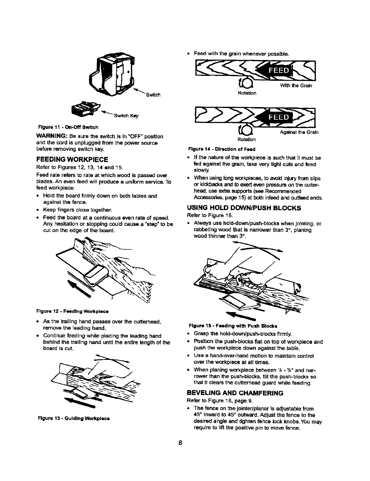
Feed with the grain whenever possible.
_._ With theGrain
Rotation
Key
Figure 11 • On-Off Switch
WARNING: Be sure the switch Is In "OFF" position
and the cord is unplugged from the power source
before removing switch key.
FEEDING WORKPIECE
Refer to Figures 12, 13, 14 and 15.
Feed rate refers to rate at which wood is passed over
blades. An even feed will produce a uniform service. To
feed workpiece:
•Hold the board firmly down on both tables and
against the fence.
• Keep fingers close together.
•Feed the board at a continuous even rate of speed.
Any hesitation or stopping could cause a "step"to be
cut on the edge of the board.
Againstthe Grain
Rotation
Figure 14 - Dlrecttan of Feed
•If the nature of the workpiece is such that ]t must be
fed against the grain, take very light cuts and feed
siowiy.
• When using longworkpiscas, to avoid injuryfrom slips
or kickbacksand to exer_even pressure on the cuiter-
heed, use extra supports (see Recommended
Accessodas, page 15) at both infeed and outfeed ends.
USING HOLD DOWN/PUSH BLOCKS
Refer to Figure 15.
•Always use hold-down/push-blocks when jolndng, or
rabbeting wood that is narrower than 3", planing
wood thinner than 3".
Figure 12 - Feeding Workplace
•As the b'alllng hand passes over the cutterheed,
remove the leading hand.
•Continue feeding while placing the leading hand
behind the trslllng hand until the entire length of the
board is cut.
Figure 13 - Guiding Workplace
Figure 15,- Feeding with Push Blocks
•Grasp the hoio-down/push-blocks firmly.
•Position the push-blocks flat on top of workpiece and
push the workpieco down against the table.
•Use ahand-over-hand motion to maintain control
over the workpiece at all times.
•When planing workplace between _-_J_"and nar-
rower than the push-blocks, tilt the push-blocks so
that It clears the cutterhead guard while feedtng.
BEVELING AND CHAMFERING
Rear to Figure 16, page 9.
•The fenco on the Jolnter/plener le adJusta_e from
45" Inward to 45" outward. Adjust the fence to the
desired angle and tighten fence lock knobs. You may
require to lift the positive pin to move fence.
8
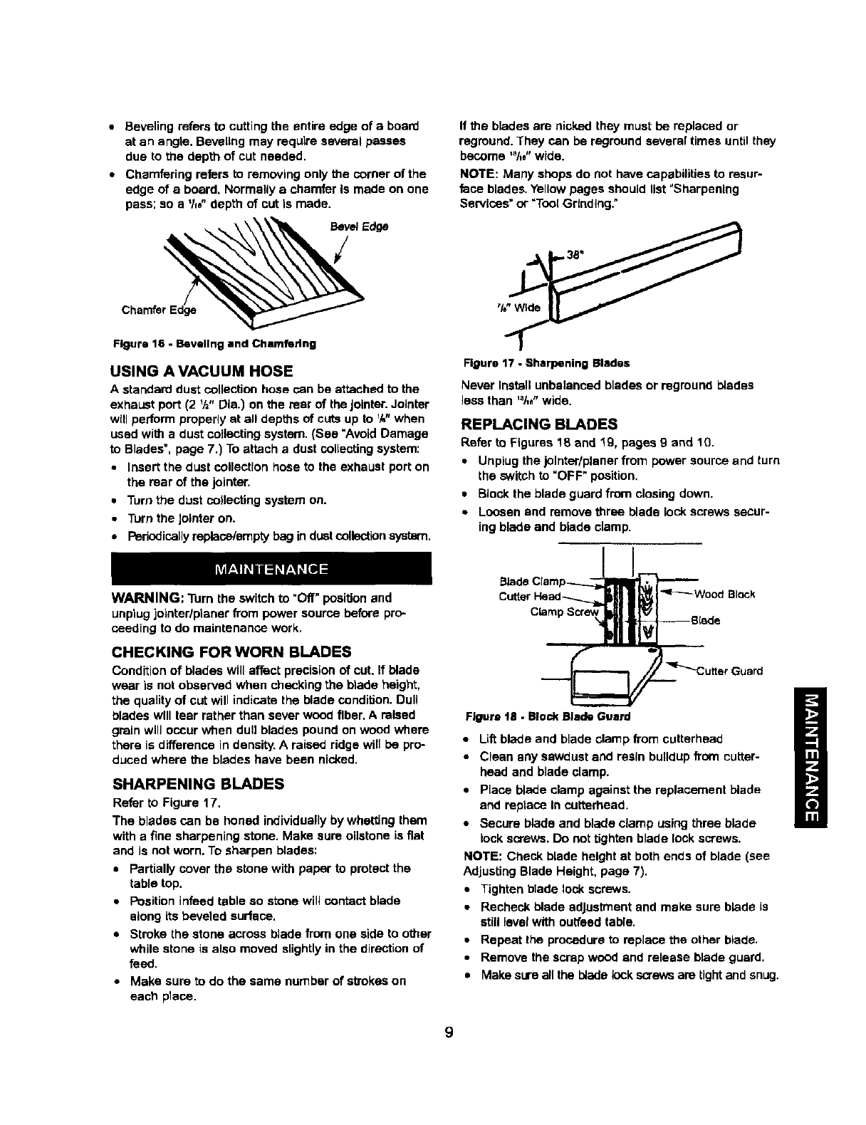
• Beveling refers to cutting the entire edge of a board
at an angle. Beveling may require several passes
due to the depth of cut needed.
•Chamfering refers to removing only the comer of the
edge of a board. Normally a chamfer Is made on one
pass; so a '/,e" depth of cut Is marie.
Charnfer_ Edge
Figure 16 - Beveling and Chamfering
USING A VACUUM HOSE
A standard dust collection hose can be attached to the
exhaust port (2 _h" Die.) on the rear of the Jointer.Jolnter
will perform properly at all depths of cuts up to '/," when
used with a dust collecting system. {See "Avoid Damage
to Blades', page 7.) To attach a dust collecting system:
•Insert the dust collection hose to the exhaust port on
the rear of the jointer.
• Turn the dust coJlecting system on.
•Turn the Jotnter on.
•Periodicallyreplace/empty bag in dustcollection system.
If the blades are nicked they must be replaced or
reground. They can be reground several times until they
become '_lte"wide.
NOTE: Many shops do not have capabilities to resur-
face blades. Yellow pages should list "Sharpening
Services" or "Tool Grinding:
Figure 17 • Sharpening Blades
Never Install unbalanced blades or reground blades
less than '_/." wide.
REPLACING BLADES
Refer to Figures 18 and "_g.pages g _nd 10.
•Unplug the jolnter/planer from power source and turn
the switch to "OFF" position.
•Block the blade guard from closing down.
•Loosen and remove three blade lock screws secur-
ing blade and blade clamp.
WARNING: Turn the switch to "Off" position and
unplug jointerlptaner from power source before pro-
ceeding to do maintenance work,
CHECKING FOR WORN BLADES
Condition of blades will affect precision of cut. If blade
wear is not observed when checking the btade height,
the quality of cut will indicate the blade condition. Dull
blades will tear rather than sever wood fiber. A raised
grain will occur when dull blades pound on wood where
there is difference in density, A raised ridge will be pro-
duced where the blades have been nicked.
SHARPENING BLADES
Refer to Figure 17.
The blades can be honed individually by whetting them
with a fine sharpening stone. Make sure oilstone is fiat
and is cot worn. To sharpen blades:
•Partially cover the stone with paper to protect the
table top.
•Position in_=edtable so stone will contact blade
along its beveled surface.
•Stroke the stone across blade from one side to other
while stone is also moved slightly in the direction of
feed.
•Make sure to do the same number of atTokeson
each place.
_usrd
Figure 1B •Block Blade Guard
•Lift blade and blade clamp from cutterhead
•Clean any sawdust and resin buildup from cutter-
head and blade clamp.
•Place blade clamp against the replacement blade
and replace In cutterhead.
•Secure blade and blade clamp using three blade
lock screws. Do not tighten blade lock screws.
NOTE: Check blade height at both ends of blade (see
Adjusting Blade Height, page 7).
•Tighten blade lock screws.
•Recheck blade edJus_nent and make sure blade is
still level with ou_eed table.
•Repeat the procedure to replace the other blade.
•Remove the scrap wood and release blade guard.
• Make sure all the i_ada lockscrews are tight and snug.
9
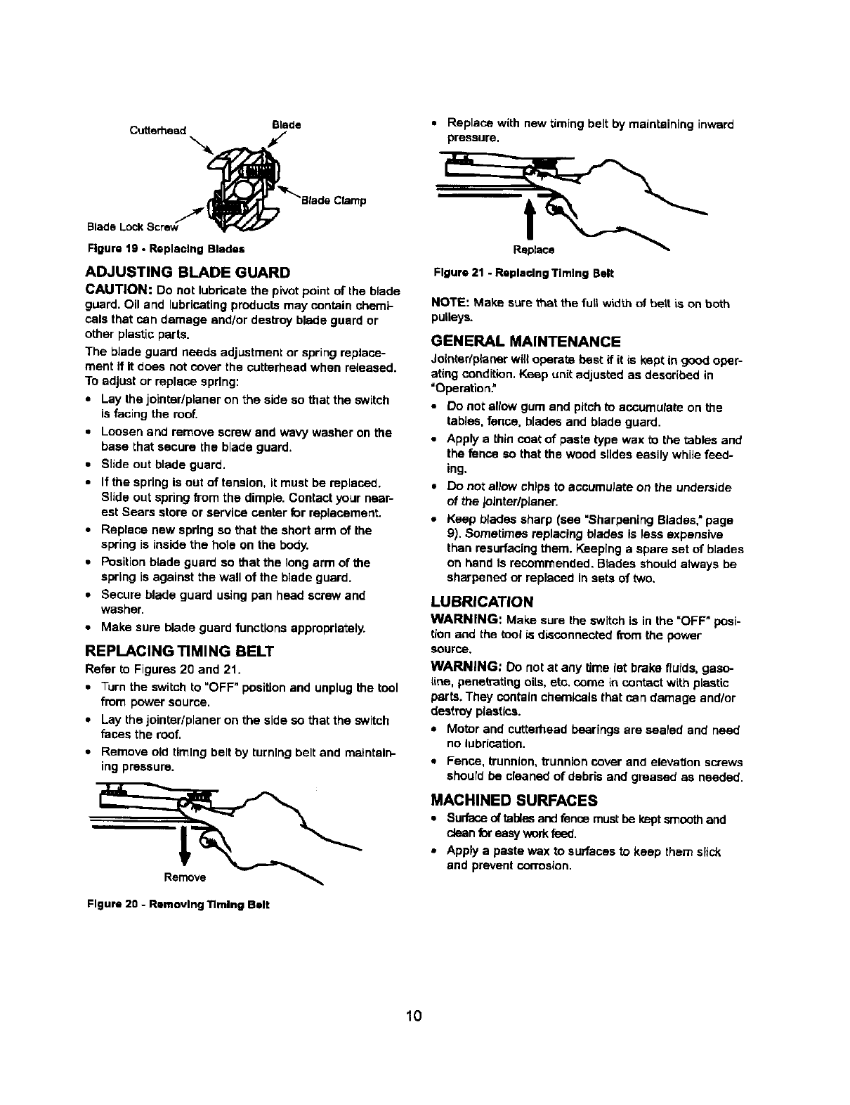
Blade • Replace with now timing belt by maintaining inward
Cutterhead fpressure.
Figure lg - Replacing Bladu Replace
ADJUSTING BLADE GUARD
CAUTION: Do not lubricate the pivot point of the b_ade
guard, Oil and lubricating products may contain chemi-
cats that can damage and/or destroy blade guard or
other plastic parts.
The blade guard needs adjustment or swing replace-
ment if it does not cover the cutterhead when released.
To adjust or replace spring:
•Lay the jointedpidner on the side so that the switch
is facing the roof,
•Loosen and remove screw and wavy washer on the
base that secure the blade guard.
•Slide out brads guard.
•If the spring Is out of tension, it must be replaced.
Slide out spring from the dimple. Contact your near-
est Sears store or service center for replacement.
•Replace new spring so that the short arm of the
swing is inside the hole on the body.
•Position blade guard so that the long arm of the
spring is aoathst the wal_of the blade gumd.
•Secure blade guard using pan head screw and
washer,
•Make sure blade guard functions appropriately.
REPLACING TIMING BELT
Refer to Figures 20 and 21.
•Turn the switch to "OFF" position and unplug the tool
from power source.
•Lay the jointer/planer on the side so that the switch
faces the roof,
•Remove old ttmtng bert by torntng belt and maintain-
ing pressure.
Rerno_
Figure 21 - Raplacthg Tlmtsg Belt
NOTE: Make sure that the full width of bert is on both
pulleys.
GENERAL MAINTENANCE
Jointadplaner will operate best if it is kept in good oper-
ating condition. Keep unit adjusted as described in
"Operation."
•Do not allow gum end pitch to accumulate Onthe
tabtes, fence, blades and blade guard,
•Apply e thin coat of paste type wax to the tables and
the fence so that the wood slides easily while feed-
ing.
•Do not allow chips to accumuJate on the underside
of the Jointer/planer,
•Keep blades sharp (see "Sharpening Blades," page
9). Sometimes replacing blades is less expensive
than resurfacing them. Keeping a spare set of blades
on hand is recommended. Blades should always be
sherpene_:lor replaced In sets of two,
LUBRICATION
WARNING: Make sure the switch is in the "OFF" posi-
tion and the tool is disconnected _om the power
source.
WARNING: Do not at any time let brake fluids, gaso-
tthe, penetrating oils, etc. come in contact with plastic
parts.They contain chernlcals that can damage and/or
destroy plastics.
•Motor and cutterhead bearings are sealed and need
no lubrication,
•Fence, trunnion, trunblon cover and elevation screws
should be cleaned of debris and greased as needed,
MACHINED SURFACES
•Surfaceof tables and fence must be kept smoothand
clean for easywork fe_.
• Apply apaste wax to surfaces to keep them slick
and prevent cowosidn.
Figure 20 -Rm-novlng Timing Belt
10
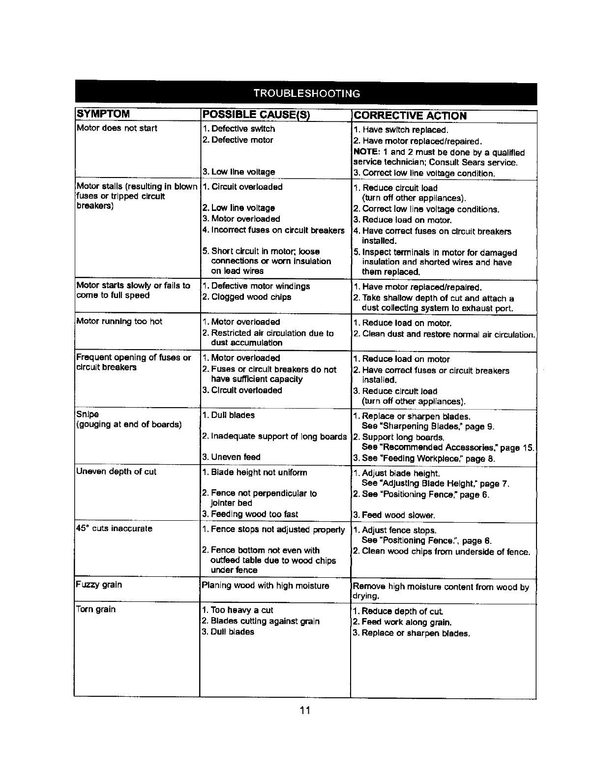
SYMPTOM
Motor does notstart
Motor stalls (resulting in blown
fuses or tripped circuit
breakers)
Motor starts slowly or fails to
coma to full speed
Motor running too hot
Frequent opening of fuses or
circuit breakers
Snipe
(gouging at end of boards)
Uneven depth of cut
45 =cuts inaccurate
Fuzzy grain
Torn grain
POSSIBLE CAUSE(S_)
1. Defective switch
2. Defective motor
3. Low line voltage
1. Circuit overloaded
2. Low line voltage
3. Motor overloaded
4. Incorrect fuses on circuit breakers
5. Short circuit in motor; loose
connections or worn insulation
on lead wires
1. Defective motor windings
2. Clogged wood chips
1. Motor overloaded
2. Restricted air circulation due to
dust accumulation
1. Motor overloaded
2. Fuses or cimult breakers do not
have sufficient capacity
3. Clmuit overloaded
1. Dull blades
2. Inadequate support of long boards
3. Uneven feed
1. Blade height not uniform
2. Fence not perpendicular to
Jointer bed
3. Feeding wood too fast
1. Fence stops not adjusted propedy
2. Fence bottom not even with
outfeed table due to wood chips
under fence
Planing wood with high moisture
1. Too heavy a cut
2. Blades cutting against grain
3. Dull blades
CORRECTIVE ACTION
1. Have switch replaced.
2. Have motor replacedlrepaired.
NOTE: 1 and 2 must be done by a qualified
service technician; Consult Sears service.
3. Correct low line voltage condition.
1. Reduce circuit load
(turn off other appliances).
2. Correct low line voltage conditions.
3. Reduce load on motor.
4. Have correct fuses on circuit breakers
installed.
5. Inspect terminals in motor for damaged
insulation and shorted wires and have
them replaced.
1. Have motor replaced/repaired.
2.Take shallow depth of cut and attach a
dust coUecting system to exhaust port.
1. Reduce load on motor.
2. Clean dust and restore normal air circulation.
1. Reduce load on motor
2. Have correct fuses or circuit breakers
installed.
3. Reduce circuit load
(turn off other appliances).
1. Replace or sharpen blades.
See "Sharpening Blades," page 9.
2. Support long boards.
See =Recommended Accessories" page 15.
3.See "Feeding Workpfece," page 8.
I1.Adjust blade height.
See "Adjusting Blade Height," page 7.
2. See =Positioning Fence," page 6.
13.Feed wood slower.
11. Adjust fence stops.
See "Positioning Fence:', page 6.
12.Clean wood chips from underside of fence.
IRemove high moisture content from wood by
drying.
1. Reduce depth of cut.
2. Feed work along grain.
3. Replace or sharpen blades.
11

NOTES
12

Model 351.286281
Figure 22 - Replacement Parts Illustration for Motor
t
2
17
7
KEY
NO.
1
2
3
4
5
6
7
8
9
10
11
12
13
14
15
18
17
PART NO.
2856.00
STD315215
2857.00
STD315205
2858.00
2859.00
STD852005
2860.00
1413.00
STD651005
5383,00
2861.00
2862.00
2863.00
1838.00
2864.00
1474.00
DESCRIPTION
Motor Cover
6201ZZ Ball Bearing
Armature with Fan
6200ZZ Ball Bearing*
Wavy Washer
Thread Forming Screw
5r'nm Lock Washer*
Stator
Strain Relief
5mm Flat Washer*
5-0,8 x 18ram Hex Head Bolt
QTY.
1
1
1
1
1
2
6
1
1
4
4
Brush Cap
Carbon Brush (set of 2)
Brush Holder
5-0.8 x 10ram Bet Screw
Motor Housing
5ram Serrated V_asher
*Standard hardware item available _ocalty
2
1
2
2
1
1
13
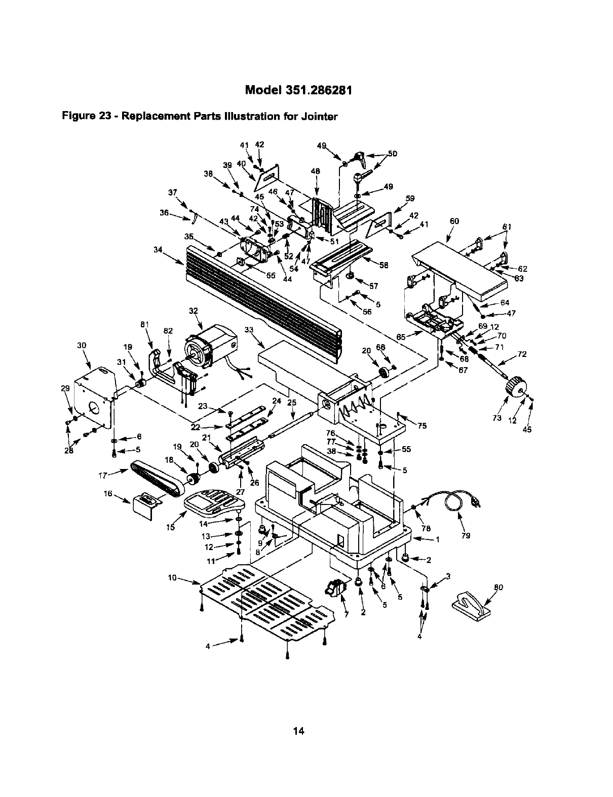
Model 351.286281
Figure 23 - Replacement Parts Illustration for Jointer
41 42 ,\
48
59
6O
3O
81
19
32
82 33
56
2O
24
78 79
14

KEY
NO.
1
2
3
4
5
6
7
8
9
10
11
PART NO.
Z693.01
4135.00
1553.00
Z895.00
3850.00
_722.00
]423.00
2892.00
3729.00
Z894.00
)361.00
QTY.
1
4
1
8
18
DESCRIPTION
Base
Foot Pad
Cord Clamp
Thread Forming Screw
5-1.0 x 16ram
Socket Head Bolt
7mm SpecialWasher
Switch
Spflng
Thread Forming Screw
Cover
5-0.8 x 8mm
Pan Head Screw
5mm Flat Washer*
7mm SpecialWasher
Wavy Washer
Blade Guard
Access Cover
Belt
Drive Pulley
6-1.0 x 6ram Set Screw
6200ZZ Ball Beadng"
Cutterhead
Blade Clamp
6-1.0 x 12mm
Socket Pan Head Screw
Blade(set of 2)
Shaft
5-0.5 x 12ram
Flat Head Screw
6-1.0 x 12ram Bet Screw
5-0.8 x lOmm
Socket Head Bolt
5mm Lock Washer*
Motor Mounting Plate
Motor Pulley
Motor
Outfeed Table
Fence
V,-20" Square Nut
Scale
Rivet
4-0.7 x 6mm Pan Head Screw
Indicator
Right Side Slotted Plate
lO
1
1
1
1
1
12 3TD851005 4
13 _723.00 1
14 3499.00 1
15 2891.00 1
16 4128.00 1
17 _887.00 1
18 Z886.00 1
19 )964.00 2
20 3TD315205 2
21 Z885.00 1
22 Z883.00 2
23 3346.0D 9
24 !9-73667 1
25 =2881.00 1
26 !3535.O0 4
27 2803.00 2
28 3855.00 4
29 BTD851005 4
30 2866.01 1
31 2889.00 1
32 2890.00 1
33 2880.02 1
34 2865.00 1
35 2866.00 4
36 2898.00 1
37 1286.00 2
38 0781.00 3
39 2896.00 1
40 2997.00 1
Standa_ hardware i_m availa_elocal_
NotShown
KEY
NO.
41
42
43
44
45
PART NO.
2872.00
9725.00
2869.00
1993.00
1903.00
46 9720.00
47 ST0840508
48 2873.00
49 9724.00
50 2874.00
51 2870.00
52 9727.00
53 2671.00
54 5383.00
55 2867.00
56 STD852006
57 2576.00
58 2875.OO
59 9726.00
90 2579.01
61 3267.00
62 9728.00
63 5461.00
64 !5223.00
65 2877.00
66 0221.00
67 ISTD840610
68 9721.00
69 2879.00
70 0761.00
71 3270.00
72 3271.00
73 3272.00
74 16780.00
75 0351.00
76 5156.00
77 STD851004
78 4137.00
79 1412.01
80 9-73666
81 16404.00
82 16405.00
2602.03
DESCRIPTION QTY.
Shoulder Bolt 2
WavyWasher 3
TrunnionHolder 1
V,-20xV_" 4
Socket Head Bdt
4-0.7 x lOmm 2
Pan Head Screw
5-0.8 x 10ram He=<Head Bolt 1
5-0.8mm Hex Nut* 3
Fence Bracket 1
6mm Bpecial Washer 2
Handle 2
Trennlon 1
Bpdng 1
Plate 1
5-0.8 x 16ram Hex H_d Bolt 1
Support Nut 1
6ram LockWasher* 6
T-Nut 1
Fence Support 1
Left Bide Slotted Plate 1
!Infeed Table 1
Bracket 4
8ram Special Washer 4
3CM1-8 Retaining Ring 4
5--0.8x 30ram Set Screw 1
Table Frame 1
3AMI-10 Ratainimj Rin91
8-1.0ram Hex Nut* 1
6-1.0 x 30ram Set Screw 1
Support Plate I.
4-0.7 x 8ram Pan Head Screw 2
Spring 1
Elevation Screw 1
Knob 1
Shoulder Bolt 1
6-1.0 x 10mm Set Screw 4
4ram Serrated Washer 2
4ram Flat Washer* 2
Grommet 1
Line Cord 1
Push Block (set) 1
Baffle 1
Thread Forming Screw 5
Owner's Manual 1
Recommended Accessories
Blade(sat of 2) / 9-73667
T
t_ Push 91o{_k(set) J9-73666
15

SEARS
Owner's Manual
Sears service is available at or through
your Sears Retail Store
or Catalogue Sales Office
How to order repair parts
SERVICE AND REPAIR PARTS
CALL 1-800-4-MY-HOME*
(%800-469-4663)
Keep this number handy should you require a
service call or need to order repair parts.
If ordering parts make sure you have the name, make and
model no. of the merchandise and the name and number
of the part you wish to order.
When ordering repair perts
always give:
1. The Part Number
2, The Part Description
3, The Model Number:
4. The name of the item:
*if callin9lOCally,please use one of the following numbers:
Regina -566-5124 Montreal -333-5740
Toronto -744-4900 Halifax. 454-2444
Kitchener -894-7590 Ottawa -738-4440
_ancouver -420-8211
WE SERVICE WHAT WE SELL.
WE MAKETHIS PLEDGE BECAUSE OUR CONCERN FOR OUR CUSTOMERS DOES NOT
ENDWITH THE SALE. TO HONOR OUR PLEDGE, WE HAVE DEVELOPED ATOP-NOTCH
SERVICE PROGRAM STAFFED BY HIGHLY TRAINED SPECIALISTS. THEIR KNOWLEDGE
OF OUR NEW PRODUCTS IS CONSTANTLY UPGRADED. THEY USE ONLY
PARTS SPECIFICALLY DESIGNED FORYOUR FINE SEARS PRODUCTS.
Sold by: SEARS CANADA INC.,TORONTO, ONTARIO, CANADA M5B 2B8
