CRAFTSMAN Router Accessory Manual L0802689
User Manual: CRAFTSMAN CRAFTSMAN Router Accessory Manual CRAFTSMAN Router Accessory Owner's Manual, CRAFTSMAN Router Accessory installation guides
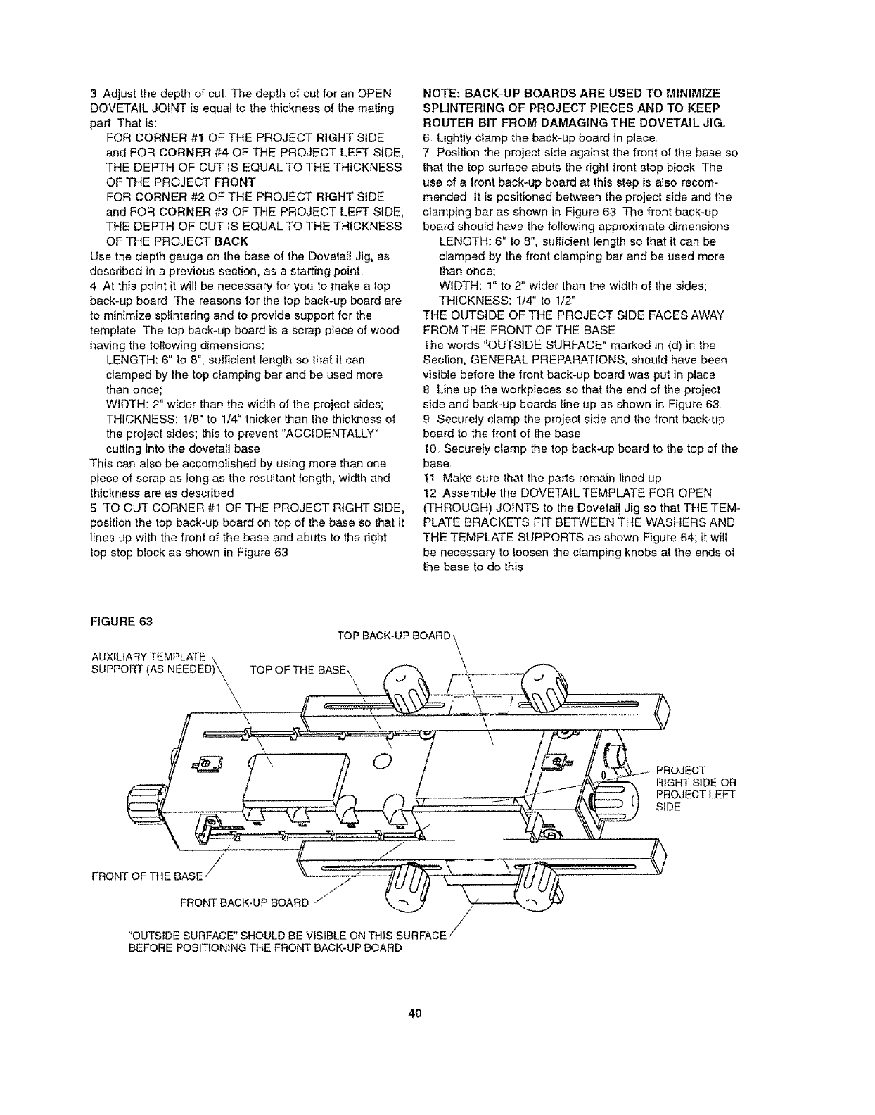
Open the PDF directly: View PDF ![]() .
.
Page Count: 52
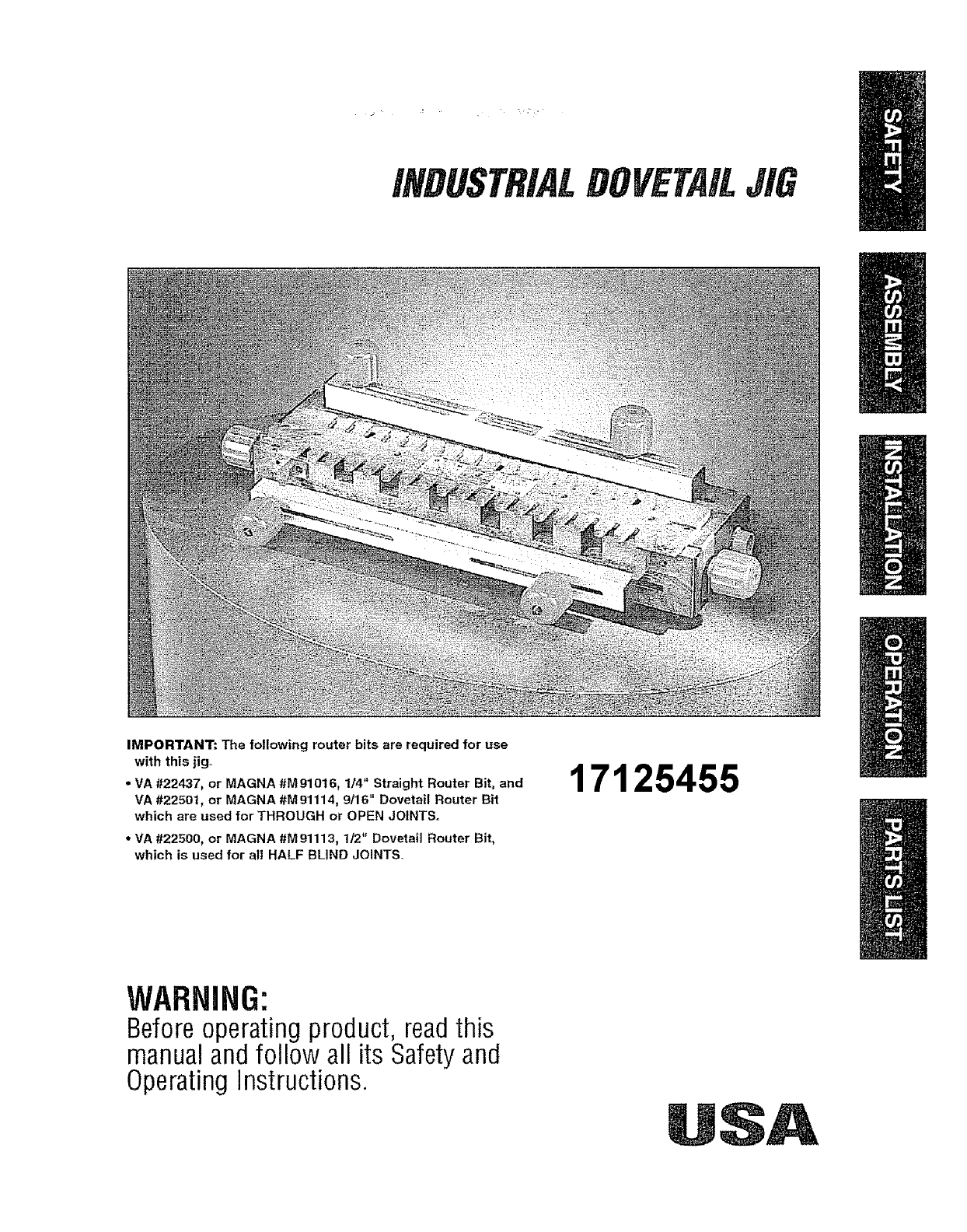
iNDUSTRiALDOVETAILJIG
IMPORTANT:. The fo!lowing router bits are required for use
with this jig-
• VA #22437, or MAGNA #M 910t6, 1/4" Straight Router Bit, and
VA #22501, or MAGNA #M91114, 9t16" Dovetail Router Bit
which are used for THROUGH or OPEN JOINTS.
•VA #22500, or MAGNA #M91113, 1t2" Dovetail Router Bit,
which is used for all HALF BLIND JOINTS.
17125455
WARNING:
Beforeoperatingproduct, readthis
manualandfollow all its Safetyand
OperatingInstructions.

General Safety Instructions for Power Tools .......................................... 3
Additional Safety Instructions for Industrial Dovetail Jig ...................... 4
Introduction ............................................................................................ ... . 5
Unpacking and Checking Contents .......................................................... 5
Assembly ..................................................... 6
Assembly of the Right Side Template Support to the Dovetail Base .................. 6
Assembly of
Assembly of
Assembly of
Assembly of
Assembly of
Assembly of
the Top Clamping Bar to the Dovetail Base .................................... 7
the Front Clamping Bar to the Dovetail Base ............................... 9
the Cam Handles and Pivot Shaft to the Dovetail Base ................ 10
the Front Stop Blocks to the Dovetail Base ................................ 13
the Top Stop Blocks to the Dovetail Base ........................................ 14
the Clamping Knobs to the Dovetail Base .................................... 14
Assembly of the Templates .......................................................................................... 15
Alignment of the Templates ..................................................................................... 16
Assembly of the Adapter Plate to the Router. ..................................................... 18
Assembly of the Guide Bushing to the Router ....................................................... 21
Installation ........................................................................ .... . . . ..... . ... .......... 22
Operation
Styles of Dovetail Joints ........................................................................................ 24
Half Blind Flush Joint ......................................................................................... 24
Half Blind Flush Offset Joint ............................................................................. 25
Half Blind Rabbeted Joint ................................................................................. 25
Open or Through Joint .................................................................................... 26
Adjusting the Depth-of-Cut of the Router Bit ...................................................... 26
Clamping the Workpieces to the Dovetail Base ................................................ 28
Making Drawers with Half Blind Flush Joints ..................................................... 29
Making Drawers with Half Blind Flush Offset Joints .......................................... 35
Making Drawers with Half Blind Rabbeted Joints .................................................. 35
Making Projects with Open (Through) Joints ....................................................... 37
Parts List .................................................................................................... 47

SAFETY GUIDELINES - DEFINITIONS
This manual contains informa-
tion that is important for you to
know and understand. This
information relates to protect-
ing YOUR SAFETY and
PREVENTING EQUIPMENT
PROBLEMS. To help you rec-
ognize this information, we use
the symbols to the righL
Please read the manual and
pay attention to these sections.
IADANGER I
URGENT SAFETYINFORMATION-A
HAZARDTHATWILLCAUSESERF
OtISINJURYORLOSSOFLIFE
I,AWARNINGI
IMPORTANTSAFETYINFORMA-
TION_A HAZARD THAT MIGHT
CAUSESERIOUSINJURYORLOSS
OFLIFE
I CAUTION]
INFORMATIONFORPREVENTING
DAMAGETOEQUIPMENT
[ NoTE]
INFORMATIONTHATYOUSHOULD
PAYSPECIALAITENTIONTO
['_WARNINGI Failure to heed all safety and operating instructions and warnings regarding use of this
product can result in serious bodily injury
1. Know your power tool
Read the owner's manual carefuify Learn its
application and limitations as welt as the specific potential
hazards peculiar to this tool
2. Ground all tools (unless double insulated)
If tool is equipped with an approved three-conductor cord
and a three-prong grounding type plug, it should be
plugged into a three hole electrical receptacle If adapter is
used to accommodate a two-hole receptacle, the adapter
wire must be attached
to a known ground (usually the screw securing
receptacle cover plate) Never remove third prong
Never connect green ground wire to a terminal
3. Keep guards in place
Maintain in working order, and in proper adjustment and
alignment
4. Remove adjusting keys and wrenches
Form a habit of checking to see that keys and adjusting
wrenches are removed from tool before turning it ON
5, Keep work area clean
Cluttered areas and benches invite accidents
Ftoor must not be slippery due to wax or sawdust
6. Avoid dangerous environment
Do not use power tools in damp or wet locations
or expose them to rain Keep work area well lighted
Provide adequate surrounding work space
7. Keep children away
All visitors should be kept a safe distance from work
area
8. Make workshop child-proof
Use padlocks, master switches, or remove starter keys
9. Do not force tools
Do not force tool or attachment to do a job it was
not designed to perform
10. Use the right tool
They wifl do the job better and safer at the rate
for which they were designed
11. Wear correct apparel
Do not wear loose clothing, gloves, neckties or
jewelry (rings, wristwatches) that may get caught
in moving parts Nomstip footwear is recommended Wear
protective hair covering to contain long hair Roll long
sleeves above the elbow
12. Use safety goggles (Head Protection)
Wear safety goggles (must comply with ANSI Standard
Z87 1) at all times A_so, use face or
dust mask, if cutting operation is dusty, and ear
protectors (plugs or muffs) during extended periods of
operation
13, Secure work
Use clamps or a vise to hold work when practical it's safer
than using your hands, and both hands
are free to operate tool
14. Do not overreach
Keep proper footing and balance at all times
15. Maintain tools with care
Keep tools sharp and clean for best and safest
performance Follow instructions for lubricating
and changing accessories
16. Disconnect tools before servicing
Before servicing, when changing accessories
such as blades, bits, cutters, etc
17. Avoid accidental starting
Make sure swilch is in OFF position before plugging in
18. Use recommended accessories
Consult the owner's manual for recommended accessories
and follow the instructions The use
of improper accessories may cause hazards
19, Never stand on tool
Serious injury could occur if the tool is tipped or ff the cut_
ring _oot is accidentally contacted DO NOT store materi-
als above or near the tool making it
necessary to stand on the toot to reach them
20. Check damaged parts
Before further use of the Iool, any guard or other
part that is damaged should be carefully checked to
ensure that it will operate properly and perform its
intended function Check for alignment of moving
parts, binding of moving parts, breakage of parts,
mounting, and any other conditions that may affect
its operation A guard or any other part that is
damaged should be properly repaired or replaced
21. Direction of feed
: Feed work into a blade or Cutter AGAINST the
direction of rotation of the blade or cutter only
22. Never leave tool running unattended
Turn power OFF DO NOT leave tool until it comes
to a comptele stop
23. Keep hands away from cutting area
24. Store idle tools
When not in use, tools should be stored in dry,
high or locked-up place - out of reach of children
25. Do not abuse cord
Keep cord away from heat, oil and sharp edges
26. Outdoor extension cords
When tool is used outdoors, use only extension
cords suitable for use outdoors and so marked
27. Never use in an explosive atmosphere
Normal sparking of the motor could ignite fumes,
flammable liquids, or combustible items
28. Drugs, alcohol, medication
DO NOT operate tool while under the influence
of drugs, alcohol, or any medication
Read and Understand this instruction book
completely BEFORE using this product
1 Always wear eye protection that complies with
ANSI Standard Z87 1
2 Noise levels vary widely To avoid possible hearing
damage, wear ear plugs or muffs when using the
Dovetail Jig for hours at a time
3 For dusty operations, wear a dust mask along
with safety goggles
4 Do not use this Dovetail Jig with router bits or
guide bushings other than those specified for the
cuts being made
5 Follow the instructions in your Router Owner's
Manual
6 Vibrations caused by the router during use can
cause fasteners to become loose Before use and
periodically during use, check all fasteners to make
sure that they are all are tight and secure
7 Do net use this product until all assembly installa-
tion steps have been completed, and you have read
and understand all safeb/and operational instruc-
tions in this manual, and the Router Owners Manual
8 Make sure that the router bit is properly positioned
in the router so that it does not contact the guide
bushing or the template when cutting
9 The Dovetail Jig must be securely mounted to a
workbench or other stable surface when in use The
front of the base should overhang the front of the
workbench by no more than 1/4" to provide clear-
ance when clamping workpieces to the Dovetail Jig
10 Do not use the Dovetail Jig as a work surface
Doing so may cause damage to the Dovetail Jig,
which can cause it to be unsafe to use A workbench
should be used for this purpose
11 This product is designed to cut fiat workpieces
Do not cut or attempt to cut workpieces that are
not flat or that are irregularly shaped.
12 This product is to be used for cutting wood work-
pieces only Do not use this product to cut metal
or any other non-wood material.
13 This product has been designed to cut work-
pieces having thicknesses of 3/8" to 1" Do not use
Ior workpieces of any other thicknesses
14 Do not clamp any workpieces to the Dovetail Jig
or make any adjustments to the Dovetail Jig unless
the router has been turned off, the router bit is not
turning, and the Router has been disconnected from
the electrical outlet
15 When setting "the-depth-of-cut" of the router
bit, make sure that the workpiece is clamped to the
Dovetail Jig in such a manner that the router bit
does not cut into the Dovetail base causing dam-
age to it or possible serious injury to you.
16 L'_WARNING_ ALWAYS UNPLUG THE
ROUTER FROM THE ELECTRICAL OUTLET
BEFORE INSTALLING OR REMOVING ROUTER
BITS FROM THE ROUTER AND WHEN ADJUST-
ING THE CUTTING DEPTH OF THE ROUTER BIT;
OR WHEN INSTALLING OR CHANGING GUIDE
BUSHINGS.
17 NEVER LIFT THE ROUTER UPWARDS WHEN
THE ROUTER IS "ON", THE ROUTER BtT IS
ROTATING, AND THE GUIDE BUSHING IS NEAR
OR TOUCHING THE TEMPLATE, BECAUSE THIS
WILL CAUSE THE ROUTER BIT TO CUT INTO
THE TEMPLATE AND DAMAGE IT
• Your Vermont American Industrial Dovetail Jig is an
accessory that is used with Routers allowing you to
make drawers, chests, and similar items requiring
dovetail joints The joints are used to make the front,
back, and sides of the workpiece
• Your Industrial Dovetail Jig comes with two tem-
plates and two guide bushings for making halt-blind
and through or open joints
• Your Industrial Dovetail Jig also comes with a
universal router adapter plate that will permit the
Industrial Dovetail Jig to be used with most popular
routers
• The Dovetail Jig will allow you to make 1" spaced
flush, flush-offset, and 3/8" rabbeted half-blind
dovetail joints
• The Dovetail Jig will also allow you to make t"
spaced open, or through, dovetail joints
• Workpieces up to 16" wide can be accommodated
oWorkpieces with thicknesses between 3f8" and 1"
can be accommodated
• The Dovetail Jig Base has six pockets molded into
its front which are gauges to aid you setting the
"depth-of- cut" for commonly used depths: 3/8", I/2",
5/8", 3/4", 7/8", and 1"
• Vermont American router bits, #22501 and #22437,
or Magna router bits, #M91113 and #M91016,
WHICH MUST BE PURCHASED SEPARATELY, are
required for making the THROUGH or OPEN joints
• Vermont American router bit, #22500, or
Magna router bit, #M91114, WHICH MUST BE
PURCHASED SEPARATELY, is required for making
the HALF-BLIND ioints
• Your Vermont American Industrial Dovetail Jig
comes with two templates and two guide bushings
Each of the templates has a label, describing the
joint that can be cut with it, along with set-up
information, the router bit and the guide bushing
required, and the the stop block setting for a
particular joint
Refer to Parts List on Page 47
• tn order to simplify handling and to minimize any
damage that may occur during shipping, your
Industrial Dovetail Jig is packaged assembled
• Separate all loose parts from the packing materials
and check each one with the illustrations and list of
parts at the end of this manual to make sure that
all loose parts are present before discarding any
packaging material
.i,A ,,anypartsarem,ss,ngorcannot
be accounted for, do not attempt to assemble, instaIl,
or use the Industrial Dovetail Jig until the missing
parts have been obtained and the product has been
assembled correctly
• Contact customer service at 1-800-742-3869, ext 8359
for missing or replacement parts
ALTHOUGHYOURINDUSTRIALDOVETAILJIG
COMESASSEMBLED,THEFOLLOWINGASSEM-
BLY INSTRUCTIONS ARE BEING INCLUDED FOR
REFERENCE PURPOSES SHOULD IT BECOME
NECESSARY FOR YOU TO DISASSEMBLE AND
REASSEMBLE THE DOVETAIL JIG
PROCEED TO THE SECTION ALIGNMENT OF
THE TEMPLATES AND THEN CONTINUE WITH
THE SECTIONS FOLLOWING ALIGNMENT OF
THE TEMPLATES
THE TEMPLATES MUST BE ALIGNED BEFORE
ANY ROUTING tS TO TAKE PLACE
TOOLS REQUIRED
- A medium sized Phillips screwdSver
° A smafl or medium adjustable wrench
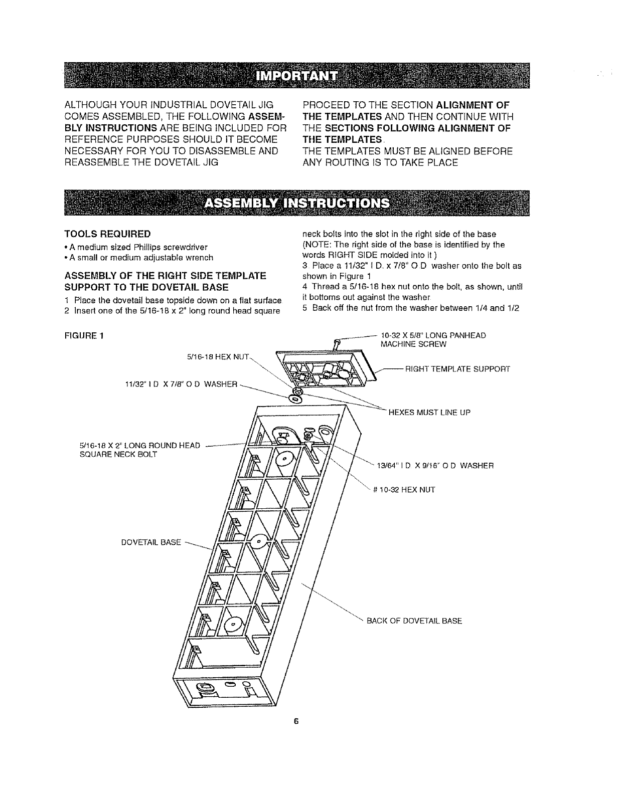
ASSEMBLY OF THE RIGHT SIDE TEMPLATE
SUPPORT TO THE DOVETAIL BASE
1 Ptace the dovetail base topside down on a fiat surface
2 insert one of the 5/16-18 x 2" long round head square
FIGURE 1
neck botts into the slot in the right side of the base
(NOTE: The right side of the base is identified by the
words RIGHT SIDE molded into it )
3 Place a 11/32" t D, x 7/8" OD washer onto the bolt as
shown in Figure 1
4 Thread a 5/16-18 hex nut onto the bolt, as shown, until
it bottoms out against the washer
5 Back off the nut from the washer between 1/4 and 1/2
10_32X 5/8" LONG PANHEAD
MACHINE SCREW
HEXES MUST LINE UP
5t16-18 X 2" LONG ROUND HEAD
SQUARE NECK BOLT
t3/64" I D X 9/t6" O D WASHER
"" # 10_32 HEX NUT
"" BACK OF DoVETAiL BASE
!UrpSAlignthenutsothatthecomersofthenu_areverti-
calfyline_JUpasshownNotethealignmentofthehex
pocketinlhetemplatesupportTheboltshouldbefreeto
movesidetoside;ifitdoesnot,loosenthenut1/3turnor
untilthecornersofthenutpointupanddown
6 Assembletherighttemplatesupporttotherightsideof
the dovetail base so that the hex nut lines up and lits into
the hex pocket in the right template support (NOTE: The
right template support has the words RIGHT SIDE molded
into it for identification )
7 Assemble a #t0-32 x 5/8" long panhead machine screw,
a 13/64" I D x 9/16" O D washer, and a #10-32 hex nut to
lhe base as shown to hold the template support in place
Securely tighten thenut and screw : :•
8 The template support should move freely front to back
along the side of the base If it does not, it means that the
5/16-18 hex nut is too tight on the bolt and should be loos-
ened To do this, remove the fasteners assembled in step
7, and remove the template support; repeat steps 4
through 7
ASSEMBLE THE LEFT SIDE TEMPLATE SUPPORT TO
THE DOVETAIL BASE THE SAME AS THE RIGHT SIDE
TEMPLATE SUPPORT WAS ASSEMBLED.
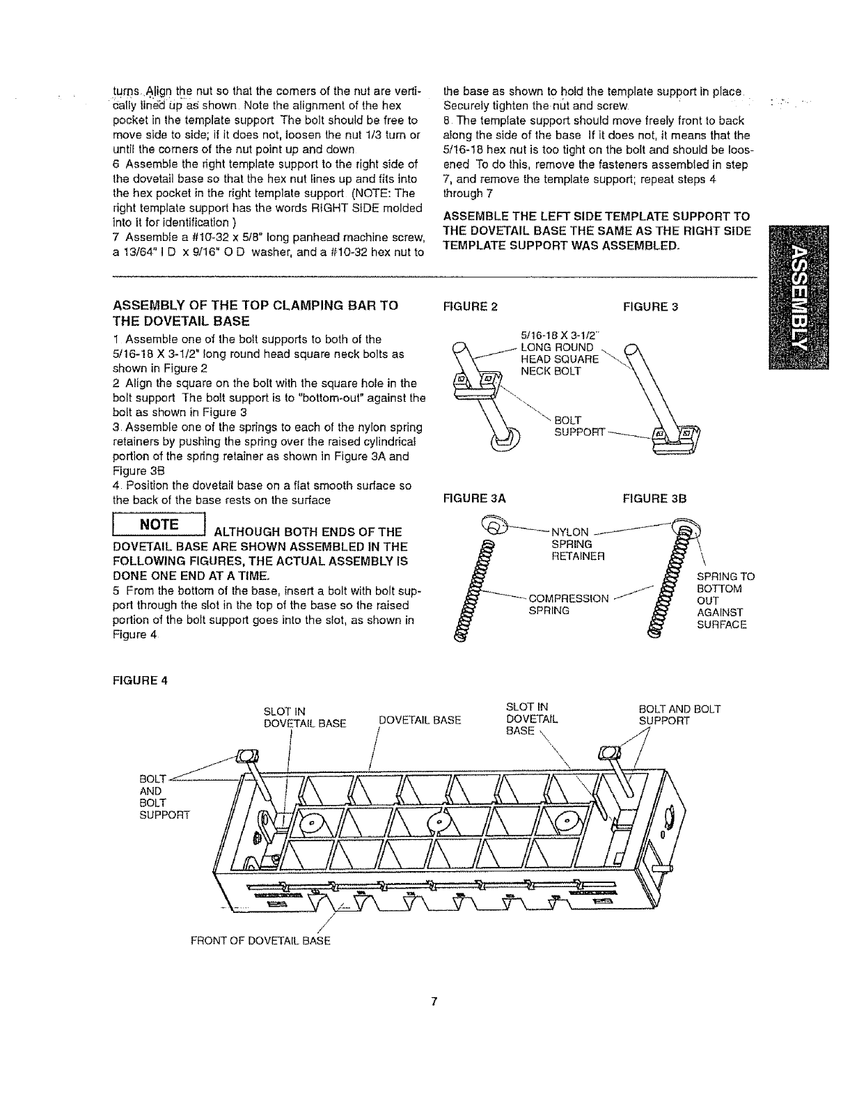
ASSEMBLY OF THE TOP CLAMPING BAR TO
THE DOVETAIL BASE
1 Assemble one of the bolt supports to both of the
5/16-18 X 3-l/2" long round head square neck bolts as
shown in Figure 2
2 Align the square on the bolt with lhe square hole in the
bolt support The bolt support is to "bottom-out" against the
bolt as shown in Figure 3
3, Assemble one of the spdngs to each of the nylon spring
retainers by pushing the spring over the raised cylindrical
portion of the spring retainer as shown in Figure 3A and
Figure 3B
4 Position the dovetail base on a fiat smooth surface so
the back of the base rests on the surface
[ NOTE ] ALTHOUGH BOTH ENDS OF THE
DOVETAIL BASE ARE SHOWN ASSEMBLED IN THE
FOLLOWING FIGURES, THE ACTUAL ASSEMBLY IS
DONE ONE END AT A TIMEo
5 From the bottom of the base, insert a bolt with bolt sup-
port through the slot in the top of the base so the raised
portion of the bolt support goes into the slot, as shown in
Figure 4
FIGURE 2
FIGURE 3A FIGURE 3B
(_ NYLON
SPRING
RETAINER
COMPRESSION /'J_f
SPRING
SPRING TO
BOTTOM
OUT
AGAINST
SURFACE
FIGURE 4
BOLT 11/
SLOT IN
DOVETAIL BASE DOVETAIL BASE
/ / SLOT IN
DOVETAIL
BASE kq
X\
BOLT AN D BOLT
SUPPORT
/
/
FRONT OF DOVETAIL BASE
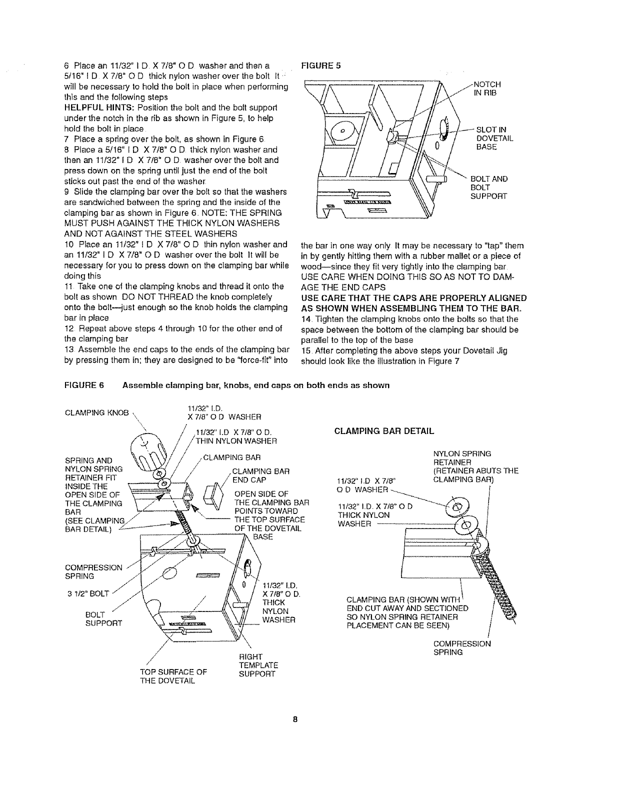
6 Placean11/32"ID X7/8"OD washerandthena
5/16"ID X7/8"OD thicknylonwasherovertheboltIt
willbenecessarytoholdtheboilinplacewhenperforming
thisandthefollowingsteps
HELPFULHINTS:Positiontheboltandtheboltsupport
underthenotchintheribasshowninFigure5,tohelp
holdtheboltinplace
7 Placeaspringoverthebolt,asshowninFigure6
8 Placea5/16"ID X7/8"QD thicknylonwasherand
thenan!1/32"ID X7/8"OD washerovertheboiland
pressdownonthespringuntiljusttheendofthebolt
sticksoutpasttheendofthewasher
g Slidetheclampingbaroverthebollsothatthewashers
aresandwichedbetweenthespringandtheinsideofthe
clampingbarasshowninFigure6 NOTE:THESPRING
MUSTPUSHAGAINSTTHETHICKNYLONWASHERS
ANDNOTAGAINSTTHESTEELWASHERS
t0 Placean11/32"tD X7/8"OD thinnylonwasherand
an11/32"ID X7/8"OD washeroverthebellItwilibe
necessaryforyoutopressdownontheclampingbarwhile
doingthis
11Takeoneoftheclampingknobsandthreaditontothe
boilasshownDONOTTHREADtheknobcompletely
ontothebolt--justenoughsotheknobhoidstheclamping
barinplace
t2 Repeatabovesteps4through10fortheotherendof
theclampingbar
13Assembletheendcapstotheendsoftheclampingbar
bypressingthemin;theyaredesignedtobe"force-fit"into
FIGURE5
j NOTCH
IN RIB
._---- SLOT IN
DOVETAIL
BASE
BOLT AND
BOLT
SUPPORT
the bar in one way only It may be necessary to "tap" them
in by gently hitting them with a rubber mallet or a piece of
wood--since they fit very tlgh|ty into the clamping bar
USE CARE WHEN DOING THIS SO AS NOT TO DAM-
AGE THE END CAPS
USE CARE THAT THE CAPS ARE PROPERLY ALIGNED
AS SHOWN WHEN ASSEMBLING THEM TO THE BAR,,
14. Tighten the clamping knobs onto the bolts so that the
space between the bottom of the clamping bar should be
parallel to the top of the base
15 After completing the above steps your Dovetail Jig
should look like the illustration in Figure 7
FIGURE 6 Assemble clamping bar, knobs, end caps on both ends as shown
CLAMPING KNOB , 11/32" I.D.
',\ X 7/8" O D WASHER
\" !t/32" I.D X 7/8" O D. CLAMPING BAR DETAIL
SPRING AND
NYLON SPRING
RETAINER FIT
]NSlDE THE
OPEN SIDE OF
THE CLAMPING
BAR
(SEE CLAMPING
BAR DETAIL)
COMPRESSION
SPRING
3 t12"
j/*
BOLT
SUPPORT
// l
//Z-
TOP SURFACE OF
THE DOVETAIL
CLAMPING BAR
•CLAMPING BAR
f_END CAP
L_.! ) OPEN SIDE OF
_-_\/ THE CLAMPING BAR
POINTS TOWARD
"_ THE TOP SURFACE
OF THE DOVETAIL
i BASE
€/1t132" I.D.
_, /X 7/8" O D
/THICK
-_ NYLON
__._WASHER
RIGHT
TEMPLATE
SUPPORT
NYLON SPRING
RETAINER
(RETAINER ABUTS THE
11/32" I,D X 7/8" CLAMPING BAR
O D WASHER __
WASHER .--[ _,
CLAMP,NG AB S.OWNW,THI
END CUT AWAY AND SECTIONED
SO NYLON SPRING RETAINER
PLACEMENT CAN BE SEEN)
COMPRESSION
SPRING
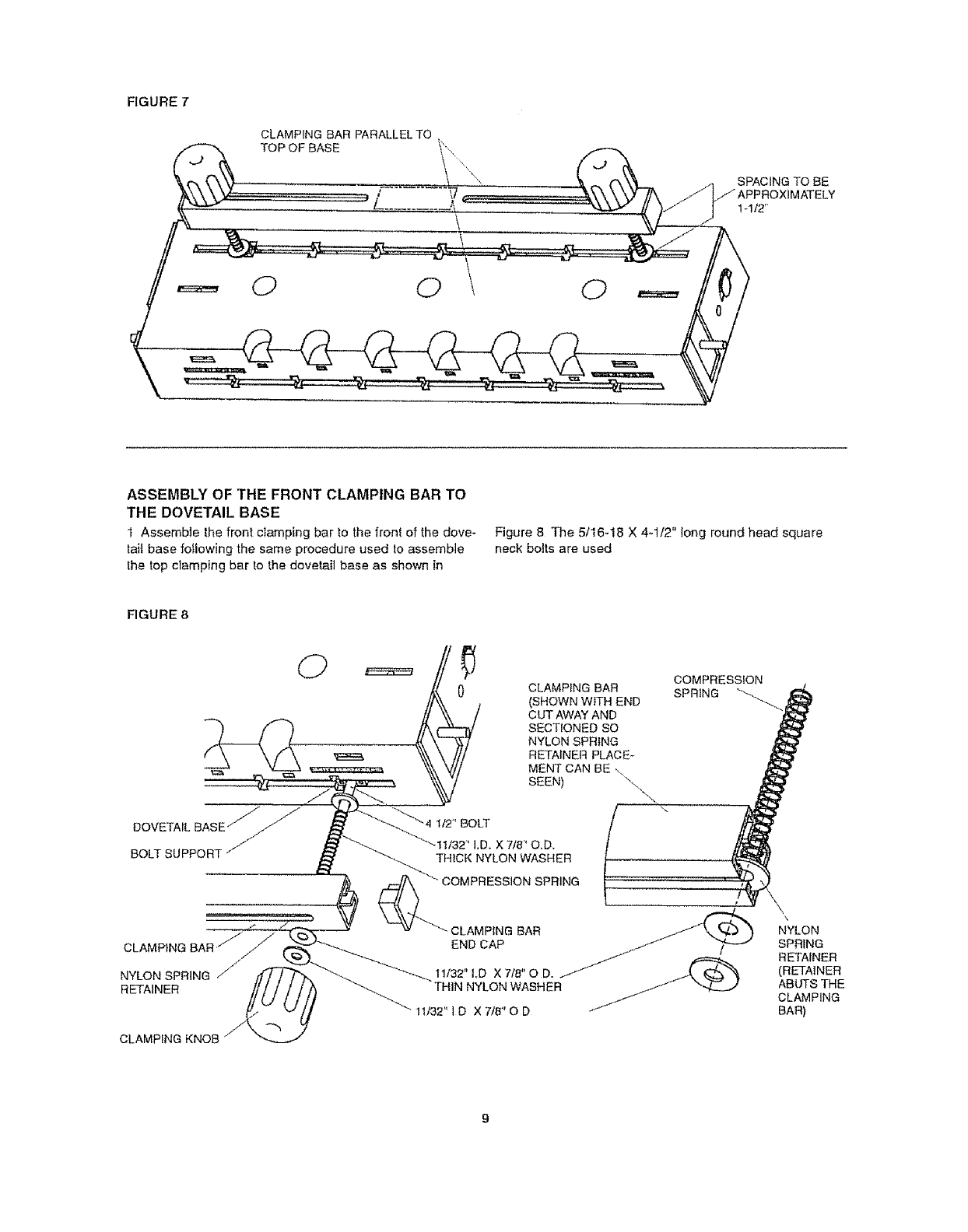
FIGURE7
CLAMPINGBARPARALLELTO
TOPOFBASE
00 0
SPACING TO BE
//APPROXIMATELY
t-112"
ASSEMBLY OF THE FRONT CLAMPING BAR TO
THE DOVETAIL BASE
t Assemble the front clamping bar !o the front of the dove-
tail base following the same procedure used Io assemble
the top clamping bar to the dovetail base as shown in
Figure 8 The 5/16-18 X 4-1/2" long round head square
neck bolts are used
FIGURE 8
DOVETAIL
BOLT SUPPORT j7
CLAMPING BAR f
NYLON SPRING /'t"
RETAINER
CLAMPING BAR
(SHOWN WITH END
CUT AWAY AND
SECTIONED SO
NYLON SPRING
RETAINER PLACEr
MENT CAN BE ,.
SEEN) "\,
\.
COMPRESSION
SPRING "__
1/2" BOLT
!1/32' I.D. X 7/8' O.D.
THICK NYLON WASHER
COMPRESSION SPRING
• CLAMPING BAR
END CAP
11132"I,D X 7/8" 0 D.
THIN NYLON WASHER
tt/32" I D X 7/8" O D
\\
\
NYLON
SPRING
RETAINER
(RETAINER
ABUTS THE
CLAMPING
BAR)
CLAMPING KNOB
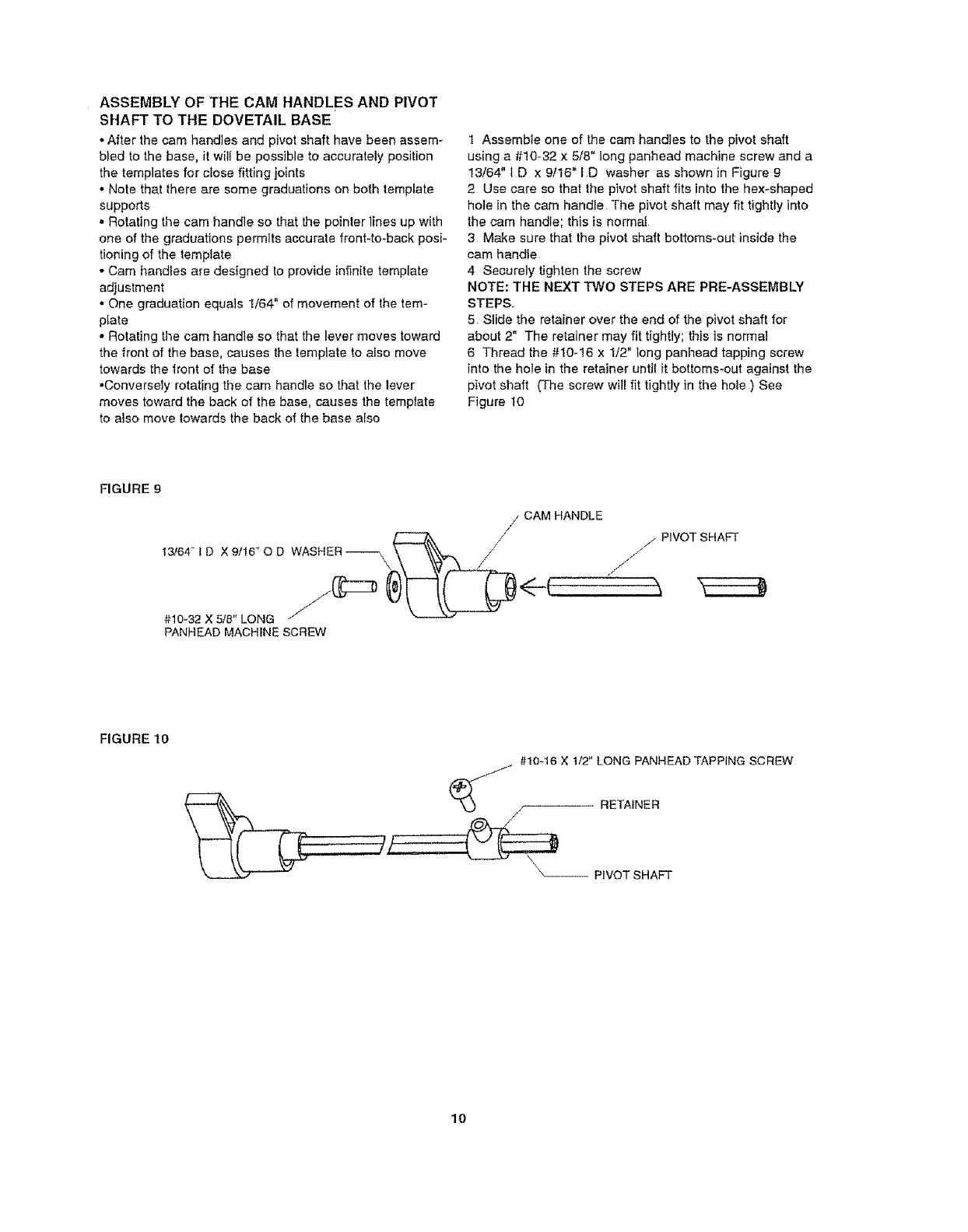
ASSEMBLYOFTHECAMHANDLESANDPIVOT
SHAFTTOTHEDOVETAILBASE
•After the cam handles and pivot shaft have been assem _
bled to the base, it wil! be possible to accurately position
the templates for close fitting joints
• Note that there are some graduations on both template
supports
• Rotating the cam handle so that the pointer lines up with
one of the graduations permits accurate front-to-back posi-
tioning of the template
• Cam handles are designed to provide infinite template
adjustment
• One graduation equals 1/64" of movement of the tem-
plate
• Rotating the cam handle so that the lever moves toward
the front of the base, causes the template to also move
towards the lront of the base
• Conversely rotating the cam handle so that the lever
moves toward the back of the base, causes the template
to also move Iowards the back of the base also
1 Assemble one of the cam handles to the pivot shaft
using a #10-32 x 5/8" tong panhead machine screw and a
13/64" I D x 9/16" ID washer as shown in Figure 9
2 Use care so that the pivot shaft fits into the hex-shaped
hole in the cam handle The pivot shaft may fit tightly into
the cam handle; this is normal
3 Make sure that the pivot shaft bottoms-out inside the
cam handie
4 Securely tighten the screw
NOTE: THE NEXT TWO STEPS ARE PRE-ASSEMBLY
STEPS.
5 Slide the retainer over the end of the pivot shaft for
about 2" The retainer may fit tightly; this is normal
6 Thread the #10-16 x 1/2" long panhead tapping screw
into the hole in the retainer until it bottoms-out against the
pivot shaft (The screw will fit tightly in the hole ) See
Figure 10
FIGURE 9
13/64"1D X 9/16_'O D WASHER _\ \
#10_32.X5/8" LONG /
PANHEAD MACHINE SCREW
/CAM HANDLE
/_PIVOT SHAFT
J j
<--LT-,:
FIGURE 10
#10-16 X 1/2" LONG PANHEAD TAPPING SCREW
_ RETAINER
/
x\__ PIVOT SHAFT
10
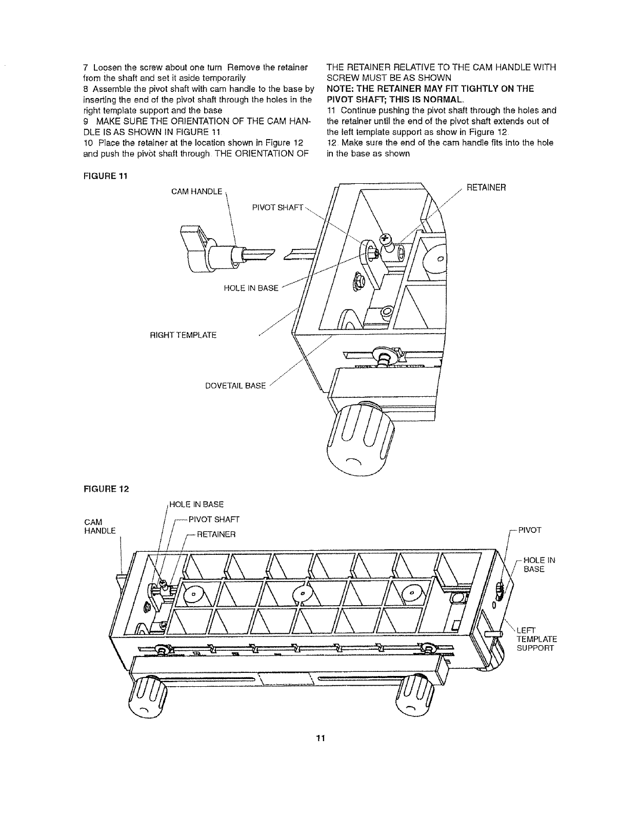
7 LoosenthescrewaboutoneturnRemovetheretainer
fromtheshaftandsetitasidetemporarily
8 Assernblethepivotshaftwithcamhandletothebaseby
insertingtheendofthepivotshaftthroughtheholesinthe
righttemplatesupportandthebase
9 MAKESURETHEORIENTATIONOF THE CAM HAN-
DLE IS AS SHOWN IN FIGURE 11
10 Place the retainer at the location shown in Figure 12
and push the pivot shaft through THE ORIENTATION OF
FIGURE 11
CAM HANDLE
PIVOT SHAFT ._
HOLE IN BASE
THE RETAINER RELATIVE TO THE CAM HANDLE WITH
SCREW MUST BE AS SHOWN
NOTE: THE RETAINER MAY FIT TIGHTLY ON THE
PIVOT SHAFT; THIS IS NORMAL,,
11 Continue pushing the pivot shaft through the holes and
the retainer until the end of the pivot shaft extends out of
the teft template support as show in Figure 12
12 Make sure the end of the cam handle fits into the hole
in the base as shown
// RETAINER
RIGHT TEMPLATE
DOVETAIL BASE /
RGURE 12
CAM
HANDLE
HOLE IN BASE
PIVOT SHAFT i,vo
• ._ ........ HOLE tN
BASE
iA ............../LJJ
11
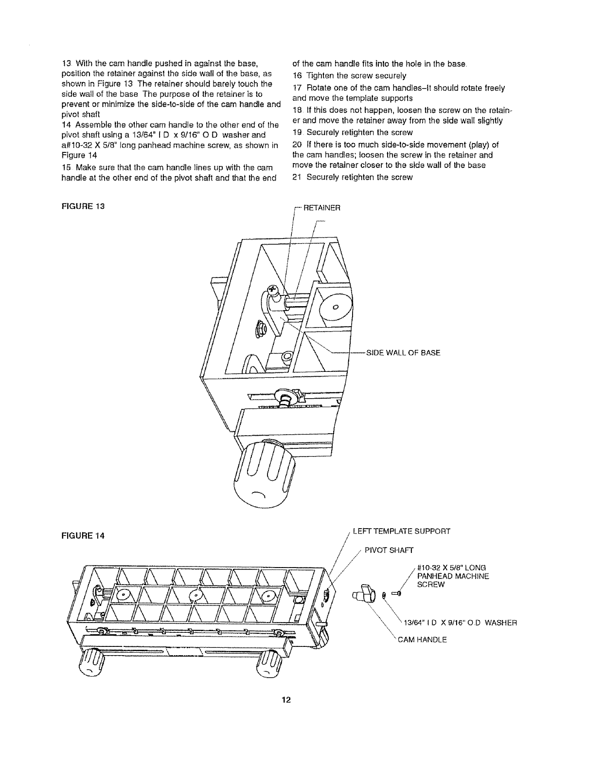
13Withthecamhandlepushedinagainstthebase,
positiontheretaineragains!thesidewallofthebase,as
showninFigure13Theretainershouldbarelytouchthe
sidewallofthebaseThepurposeoftheretaineristo
preventorminimizetheside-to-sideofthecamhandleand
pivotshaft
14Assembletheothercamhandletotheotherendofthe
pivotshaftusinga13/64"1Dx 9/16"OD washerand
a#10-32X5/8"longpanheadmachinescrew,asshownin
Figure14
15Makesurethatthecamhandlelinesupwiththecam
handleattheotherendofthepivotshaftandthattheend
of the cam handle fits into the hole in the base
16 Tighten the screw securely
17 Rotate one of the cam handles-It should rotate freely
and move the template supports
18 If this does not happen, loosen the screw on the retain-
er and move the retainer away from the side wall slightly
19 Securely retighten the screw
20 If there is too much side-to-side movement (play) of
the cam handles; loosen the screw in the retainer and
move the retainer closer to the side wall of the base
21 Securely retighten the screw
FIGURE 13
_L OF BASE
FIGURE 14 LEFT TEMPLATE SUPPORT
j PIVOT SHAFT
/
J// / #t0_32 X 5/8" LONG
\\ X 9/16" O D WASHER
\" CAM HANDLE
12
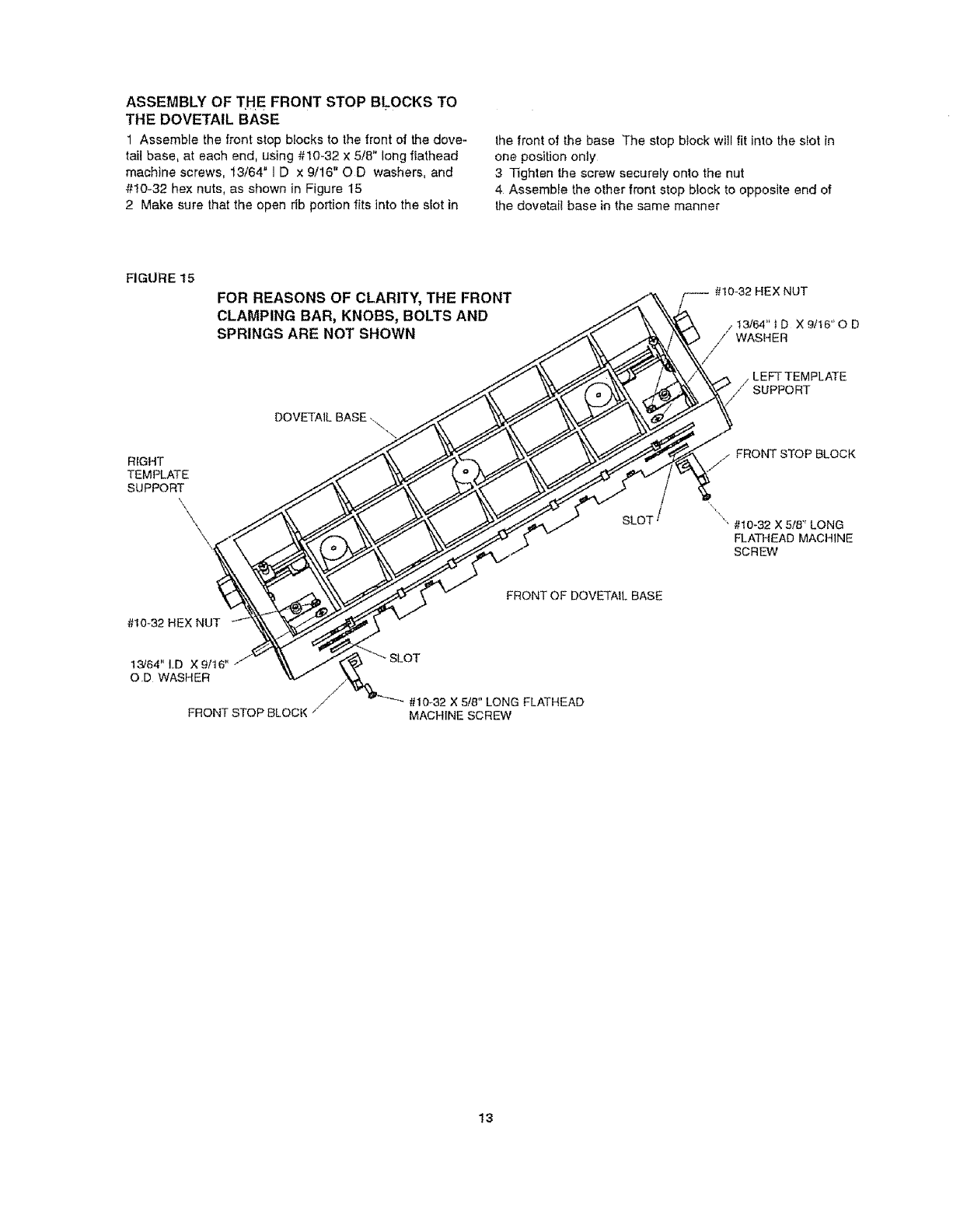
ASSEMBLY OF THE FRONT STOP BLOCKS TO
THE DOVETAIL BASE
1 Assemble the front stop blocks to the front of the dove-
tail base, at each end, using #10-32 x 5/8" long flathead
machine screws, 13/64" I D x 9/16" O D washers, and
#!0-32 hex nuts, as shown in Figure 15
2 Make sure that the open rib portion fits into the slot in
the front of the base The stop block will fit into the slot in
one position only
3 Tighten the screw securely onto the nut
4 Assemble the other front stop block to opposite end of
the dovetail base in the same manner
FIGURE 15
FOR REASONS OF CLARITY, THE FRONT
CLAMPING BAR, KNOBS, BOLTS AND
SPRINGS ARE NOT SHOWN
DOVETAIL BASE
RIGHT _
TEMPLATE ../.,.._ \'_ 7
SUPPORT _____/_\ _ "_
\\
OD WASHER V /i,'_&.
FRONT STOP BLOCK /
,,o 32HExNUT
/L%;f PLATE
_T_// FRONT STOP BLOCK
" #10-32 X 5/8" LONG
FLATHEAD MACHINE
SCREW
FRONT OF DOVETAIL BASE
#t0-,32 X 5/8" LONG FLATHEAD
MACHINE SCREW
t3
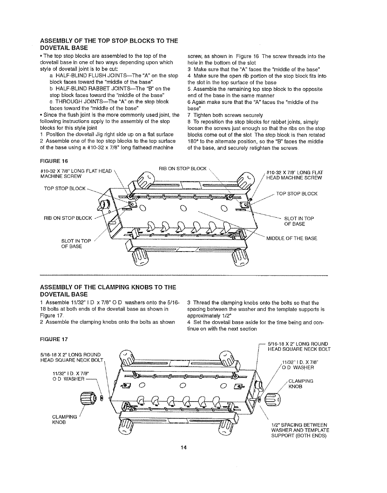
ASSEMBLY OF THE TOP STOP BLOCKS TO THE
DOVETAIL BASE
• The top stop blocks are assembled to the top of the
dovetail base in one of two ways depending upon which
style of dovetail joint is to be cut:
a HALF-BLIND FLUSH JOINTS--The "A" on the stop
block faces toward the "middle of the base"
b HALF-BLIND RABBET JOiNTS--The "B" on the
stop block faces toward the "middle of the base"
c THROUGH JOINTS---The "A" on the stop block
faces toward the "middle of the base"
, Since the flush joint is the more commonly used joint, the
following instructions apply to the assembly of the stop
blocks for this style joint
1 Position the dovetait Jig right side up on a flat surface
2 Assemble one of the top stop blocks to the top surface
of the base using a #10-32 x 7/8" long flathead machine
screw, as shown in Figure t6 The screw threads into the
hole in the bottom of the slot
3Make sure that the "A" faces the "middte of the base"
4 Make sure the open rib portion of the stop block fits into
the slot in the top surface of the base
5 Assemble the remaining top stop block to the opposite
end of the base in the same manner
6 Again make sure that the "A" faces the "middle of the
base"
7 Tighten both screws securely
8 To reposition the stop blocks for rabbet joints, simpty
loosen the screws just enough so that the dbs on the stop
blocks come out of the slot The stop block is then rotated
180 ° to the attemate position, so the "B" faces the middle
of the base, and securefy retighten the screws
FIGURE 16
#10-32 X 7/8" LONG FLAT HEAD \
MACHINE SCREW \
TOP STOP BLOCK
RIB ON STOP BLOCK ,
\\
#10-32 X 7/8" LONG FLAT
MACHINE SCREW
RIB ON STOP BLOCK
/'
SLOT IN TOP //
OF BASE
SLOT IN TO P
OF BASE
BASE
ASSEMBLY OF THE CLAMPING KNOBS TO THE
DOVETAIL BASE
1 Assemble 11/32" ID x 7/8" O D washers onto the 5/!6-
18 bolts at both ends of the dovetail base as shown in
Figure 17.
2 Assemble the clamping knobs onto the bolts as shown
FIGURE 17
5/16-18 X 2" LONG ROUND
HEAD SQUARE NECK BOLT
1t132" I D X 7/8"
OD
3 Thread the clamping knobs onto the bolts so that the
spacing between the washer and the template supports is
approximately 1/2"
4 Set the dovetail base aside for the time being and con-
tinue on with the next section
5/16-18 X 2" LONG ROUND
HEAD SQUARE NECK BOLT
/CLAMPING
// KNOB
CLAMPING /
KNOB
14
\
1/2" SPACING BETWEEN
WASHER AND TEMPLATE
SUPPORT (BOTH ENDS)
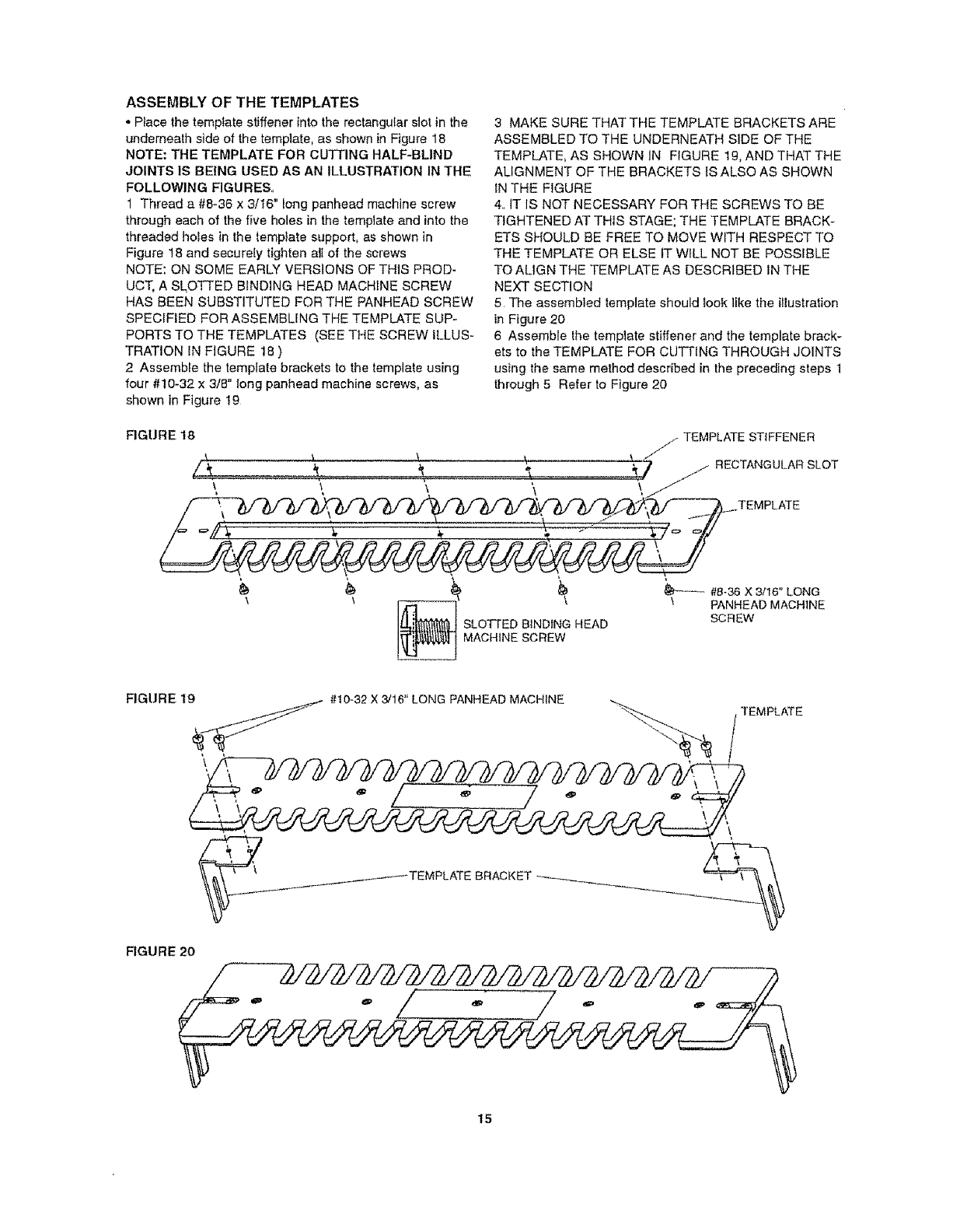
ASSEMBLY OF THE TEMPLATES
•Ptace the template stiffener into the rectangular slot in the
underneath side of the template, as shown in Figure 16
NOTE: THE TEMPLATE FOR cUTTING HALF-BLIND
JOINTS 1S BEING USED AS AN ILLUSTRATION IN THE
FOLLOWING FIGURES.
1 Thread a #8-36 x 3/16" long panhead machine screw
through each of the five holes in the template and into the
threaded holes in the template support, as shown in
Figure 18 and securely tighten all of the screws
NOTE: ON SOME EARLY VERSIONS OF TH1S PROD-
UCT, A SLOTTED BINDING HEAD MACHINE SCREW
HAS BEEN SUBSTITUTED FOR THE PANHEAD SCREW
SPECIFIED FOR ASSEMBLING THE TEMPLATE SUP-
PORTS TO THE TEMPLATES (SEE THE SCREW ILLUS-
TRATION IN FIGURE 18 )
2 Assemble the template brackets to the template using
four #10-32 x 3/8" long panhead machine screws, as
shown in Figure t9
3MAKE SURE THAT THE TEMPLATE BRACKETS ARE
ASSEMBLED TO THE UNDERNEATH SIDE OF THE
TEMPLATE, AS SHOWN IN FIGURE lg, AND THAT THE
ALIGNMENT OF THE BRACKETS iS ALSO AS SHOWN
IN THE FIGURE
4., IT IS NOT NECESSARY FOR THE SCREWS TO BE
TIGHTENED AT THIS STAGE; THE TEMPLATE BRACK-
ETS SHOULD BE FREE TO MOVE WITH RESPECT TO
THE TEMPLATE OR ELSE IT WILL NOT BE POSSIBLE
TO ALIGN THE TEMPLATE AS DESCRIBED iN THE
NEXT SECTION
5 The assembled template should took like the illustration
in Figure 20
6 Assemble the template stiffener and the template brack-
ets to the TEMPLATE FOR CUTTING THROUGH JOINTS
using the same method described in the preceding steps 1
through 5 Refer to Figure 20
FIGURE 18
\ \ \
!_' _ TEMPLATE STIFFENER
RECTANGULAR SLOT
TEMPLATE
\ \ \
SLOTTED BINDING HEAD
MACHINE SCREW
_--- #8-36 X 3/t6" LONG
\ PANHEAD MACHINE
SCREW
\\ '\
\
/TEMPLATE BRACKET "_--,o
TEMPLATE
FIGURE 20
15
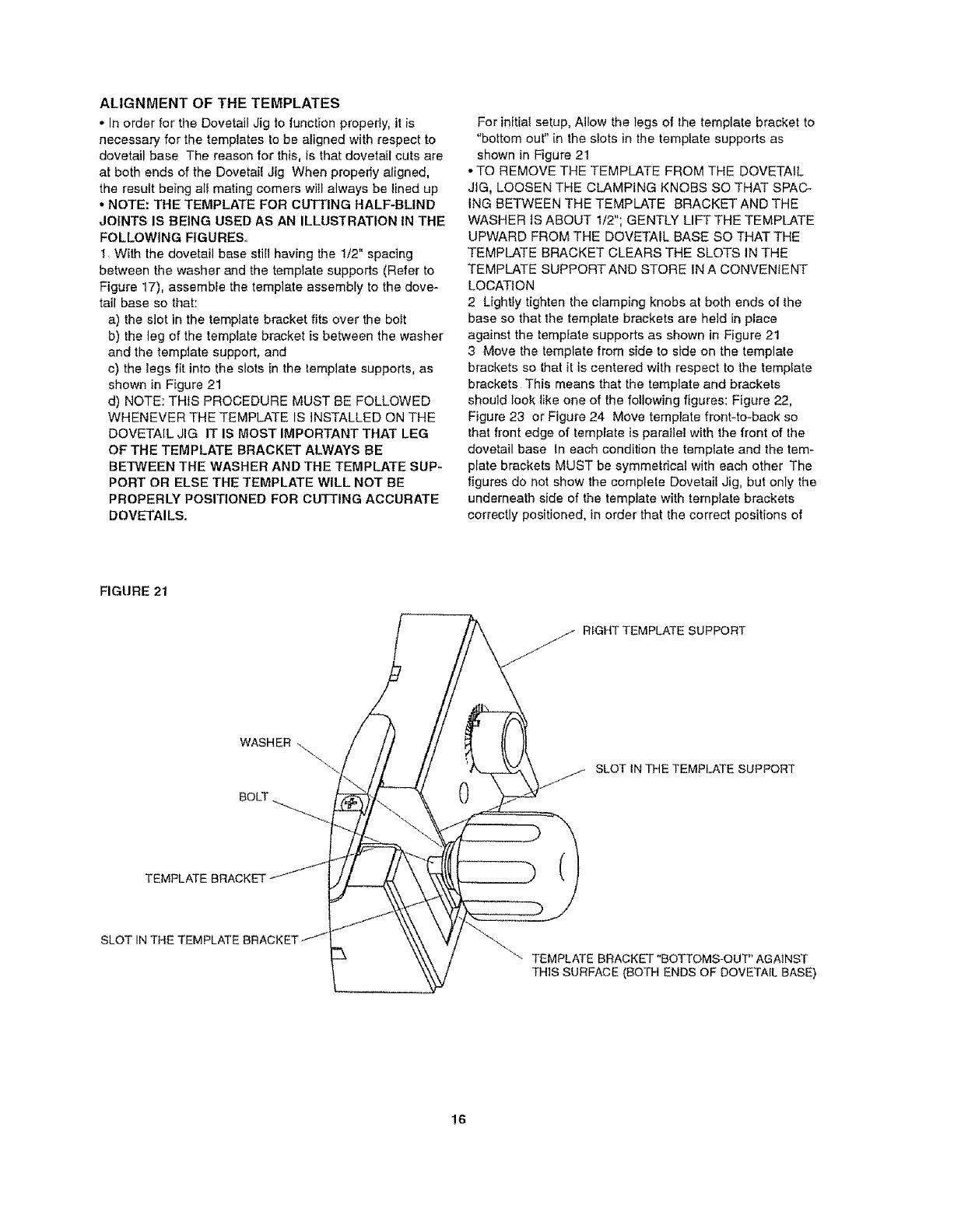
ALIGNMENTOFTHETEMPLATES
•In order for the Dovetail Jig to function properly, it is
necessary' for the templates to be aligned with respect to
dovetail base The reason for this, is that dovetail cuts are
at both ends of the Dovetail Jig When properly aligned,
the result being all mating comers wi}l always be lined up
• NOTE: THE TEMPLATE FOR CUTTING HALF-BLIND
JOINTS IS BEING USED AS AN ILLUSTRATION IN THE
FOLLOWING FIGURES°
t= With the dovetail base stiB having the 1/2" spacing
between the washer and the template supports (Refer to
Figure 17), assemble the template assembly to the dove-
tail base so that:
a) the slot in the template bracket fits over the bo_t
b) the leg of the template bracket is between the washer
and the template support, and
c) the legs fit into the slots in the template supports, as
shown in Figure 21
d) NOTE: THIS PROCEDURE MUST BE FOLLOWED
WHENEVER THE TEMPLATE iS INSTALLED ON THE
DOVETAIL JIG IT IS MOST IMPORTANT THAT LEG
OF THE TEMPLATE BRACKET ALWAYS BE
BETWEEN THE WASHER AND THE TEMPLATE SUP-
PORT OR ELSE THE TEMPLATE WILL NOT BE
PROPERLY POSITIONED FOR CUTTING ACCURATE
DOVETAILS,
For initia! setup, Allow the legs of the template bracket to
"bottom out" in the slots in the template supports as
shown in Figure 21
• TO REMOVE THE TEMPLATE FROM THE DOVETAIL
JIG, LOOSEN THE CLAMPING KNOBS SO THAT SPAC-
ING BETWEEN THE TEMPLATE BRACKET AND THE
WASHER IS ABOUT 1/2"; GENTLY LIFTTHE TEMPLATE
UPWARD FROM THE DOVETAIL BASE SO THAT THE
TEMPLATE BRACKET CLEARS THE SLOTS IN THE
TEMPLATE SUPPORT AND STORE IN A CONVENIENT
LOCATION
2 Lightly tighten the clamping knobs at both ends of the
base so that the template brackets are he]d in place
against the template supports as shown in Figure 21
3Move the template from side to side on the templale
brackets so Ihat it is centered with respect to the template
brackets This means that the template and brackets
should took like one of the following figures: Figure 22,
Figure 23 or Figure 24 Move template front-to-back so
that front edge of template is parallel with the front of the
dovetail base In each condition the template and the tem-
plate brackets MUST be symmetrical with each other The
figures do not show the complete Dovetail Jig, but only the
underneath side of the tempJate with template brackets
correctly positioned, in order that the correct positions of
FIGURE 21
jj RtGHTTEMPLATE SUPPORT
BOLT
/SLOT tN THE TEMPLATE SUPPORT
TEMPLATE BRACKET
SLOT
LTEMPLATE BRACKET "BOTTOMS-OUT" AGAINST
THIS SURFACE (BOTH ENDS OF DOVETAIL BASE)
16
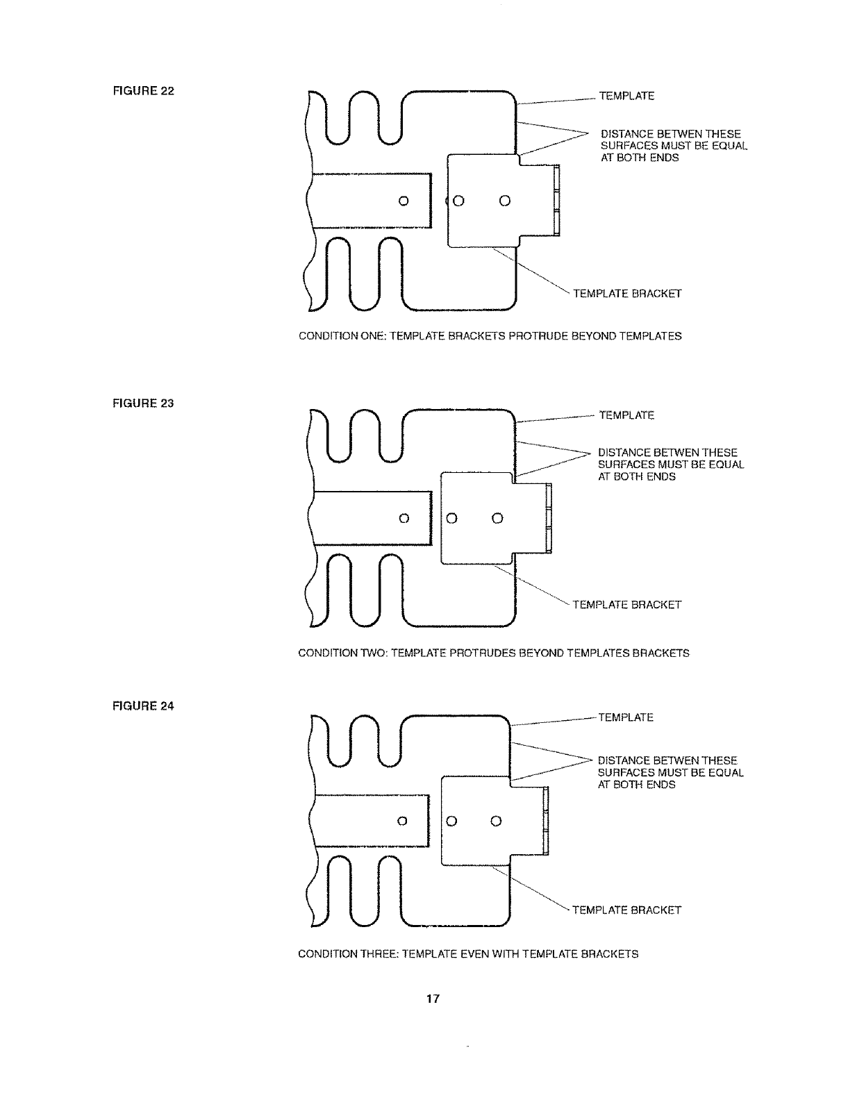
FIGURE22
(
OO
DISTANCE BETWEN THESE
SURFACES MUST BE EQUAL
AT BOTH ENDS
TEMPLATE BRACKET
CONDITION ONE: TEMPLATE BRACKETS PROTRUDE BEYOND TEMPLATES
FIGURE 23
'O
TEMPLATE BRACKET
CONDITION TWO: TEMPLATE PROTRUDES BEYOND TEMPLATES BRACKETS
FIGURE 24 rLr
olio
________---_ TEMPLATE
AT BOTH ENDS
0
-TEMPLATE BRACKET
CONDITION THREE: TEMPLATE EVEN WITH TEMPLATE BRACKETS
17
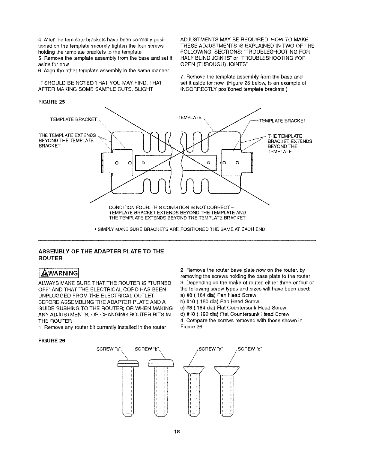
4 Afterthetemplatebracketshavebeencorrectlyposi-
tionedonthetemplatesecurelytightenthefourscrews
holdingthe template brackets to the template
5 Remove the template assembly from the base and set it
aside for now
6 Align the other template assembly in the same manner
IT SHOULD BE NOTED THAT YOU MAY FIND, THAT
AFTER MAKING SOME SAMPLE CUTS, SLIGHT
FIGURE 25
TEMPLATE BRACKET ,\
THE TEMPLATE EXTENDS
BEYOND THE TEMPLATE
BRACKET
ADJUSTMENTS MAY BE REQUIRED HOW TO MAKE
THESE ADJUSTMENTS IS EXPLAINED IN TWO OF THE
FOLLOWING SECTIONS: "TROUBLESHOOTING FOR
HALF BLIND JOINTS" or "TROUBLESHOOTING FOR
OPEN (THROUGH) JOINTS"
7 Remove the template assembly from the base and
set it aside for now (Figure 25 below, is an example of
INCORRECTLY positioned template brackets )
TEMPLATE ,
\,,\
o o
BRACKET EXTENDS
BEYOND THE
TEMPLATE
CONDITION FOUR: THIS CONDITION IS NOT CORRECT -
TEMPLATE BRACKET EXTENDS BEYOND THE TEMPLATE AND
THE TEMPLATE EXTENDS BEYOND THE TEMPLATE BRACKET
•SIMPLY MAKE SURE BRACKETS ABE POSmONED THE SAME AT EACH END
ASSEMBLY OF THE ADAPTER PLATE TO THE
ROUTER
[A¢kWARNING]
ALWAYS MAKE SURE THATTHE ROUTER IS q*URNED
OFF" AND THATTHE ELECTRICAL CORD HAS BEEN
UNPLUGGED FROM THE ELECTRICAL OUTLET
BEFORE ASSEMBLING THE ADAPTER PLATE AND A
GUIDE BUSHING TO THE ROUTER; OR WHEN MAKING
ANY ADJUSTMENTS, OR CHANGING ROUTER BITS IN
THE ROUTER
1 Remove any router bit currently installed in the router
FIGURE 26
SCREW ':a_'_,
i i
J I
tI
I I
1 I
tI
SCREW "b"_\
I I
I I
I I
t I
I I
I I
I I
I I
I I
I I
i i
2 Remove the router base plate now on the router, by
removing the screws holding the base plate to time router
3 Depending on the make of router, either three or four of
the loIIowing screw types and sizes will have been used:
a) #8 ( 164 dia) Pan Head Screw
b) #t0 (I90 din) Pan Head Screw
c) #8 ( 164 din) Flat Countersunk Head Screw
d) #10 ( t90 dia) Flat Countersunk Head Screw
4 Compare the screws removed with those shown in
Figure 26
SCREW 'c"
I 1
I 1
I 1
i 1
i t
SCREW "d"
I t
i *
18
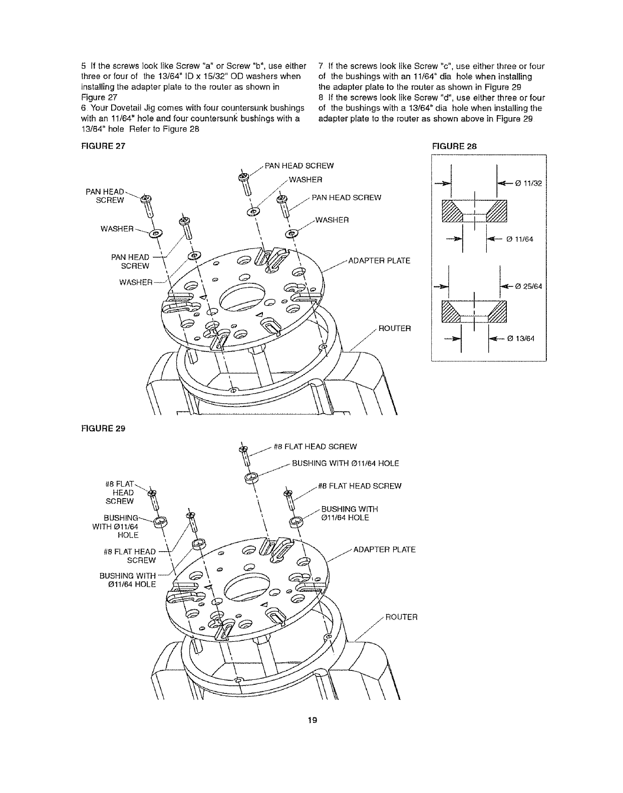
5 If the screws look like Screw "a" or Screw "b", use either
three or four of the 13/64" ID x 15/32" OD washers when
installing the adapter plate to the router as shown in
Figure 27
6 Your Dovetail Jig comes with four countersunk bushings
with an 11/64" hole and four countersunk bushings with a
13/64" hole Refer to Figure 28
FIGURE 27
7 If the screws look like Screw "c", use either three or four
of the bushings with an 11/64" din hofe when installing
the adapter plate to the router as shown in Figure 29
8 If the screws look like Screw "d", use either three or four
of the bushings with a 13/64" dia hole when installing the
adapter plate to the router as shown above in Figure 29
FIGURE 28
SCREW
PAN HEAD
SCREW
, PAN HEAD SCREW
i/WASHER
//PAN HEAD SCREW
(_jWASHER
4
4
0 11/32
--O t1/64
O 25/64
F O 13/64
FIGURE 29
HEAD
SCREW
BUSHING--.-.
WITH Oll/64
HOLE
SCREW
BUSHING
Oll/64 HOLE
d_ #8 FLAT HEAD SCREW
'_ BUSHING WITH Otl/64 HOLE
"-_,\ _j #8 FLAT HEAD SCREW
\, '0_ /BUSHING WITH
\ _/Oll/64 HOLE
PLATE
19
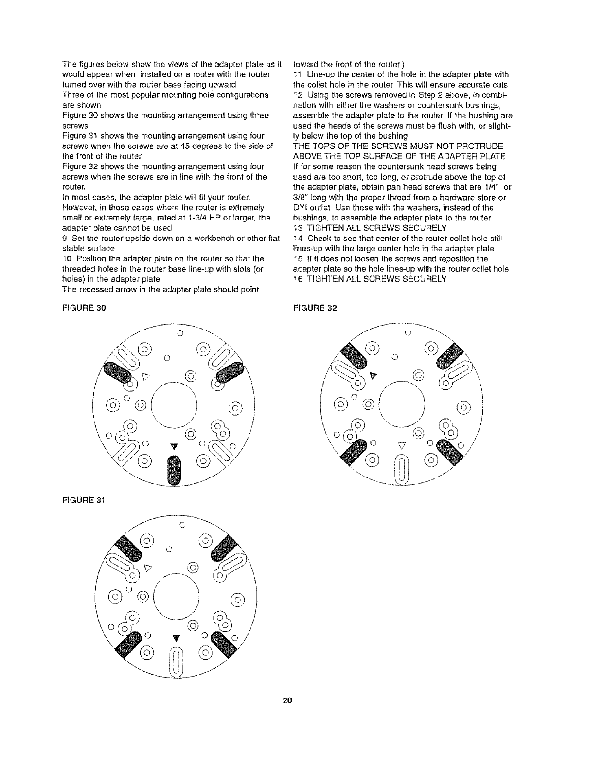
Thefiguresbelowshowtheviewsoftheadapterplateasit
wouldappearwheninstalledonarouterwiththerouter
turnedoverwiththerouterbasefacingupward
Threeofthemostpopularmountingholeconfiguralions
areshown
Figure30showsthemountingarrangementusingthree
screws
Figure31showsthemountingarrangementusingfour
screwswhenthescrewsareat45degreestothesideof
the front of the router
Figure 32 shows the mounting arrangement using four
screws when the screws are in line with the front of the
router
In most cases, the adapter plate will fit your router
However, in those cases where the router is extremely
smatl or extremely large, rated at 1-3/4 HP or larger, the
adapter plate cannot be used
g Set the router upside down on a workbench or other flat
stable surface
10 Position the adapter plate on the router so that the
threaded holes in the router base line-up with slots (or
holes) in the adapter plate
The recessed arrow in the adapter plate should point
FIGURE 30
©
©
toward the front of the router)
11 Line-up the center of the hole in the adapter plate with
the collet hole in the router This will ensure accurate cuts
I2 Using the screws removed in Step 2 above, in combi_
nation with either the washers or countersunk bushings,
assemble the adapter plate Io the router if the bushing are
used the heads of the screws must be flush with, or slight-
ly below the top of the bushing
THE TOPS OF THE SCREWS MUST NOT PROTRUDE
ABOVE THE TOP SURFACE OF THE ADAPTER PLATE
If for some reason the countersunk head screws being
used are too short, too long, or protrude above the top of
the adapter plate, obtain pan head screws that are 1/4" or
3/8" long with the proper thread from a hardware store or
DYI outlet Use these with the washers, instead of the
bushings, to assemble the adapter plate to the router
t3 TIGHTEN ALL SCREWS SECURELY
14 Check to see that center of the router co]Iet hole still
lines-up with the large center ho_e in the adapter plate
15 If it does not loosen the screws and reposition the
adapter plate so the hole Iines-up with the router collet hole
16 TIGHTEN ALL SCREWS SECURELY
FIGURE 32
©
©
/
FIGURE 31
©°@ ©
2O
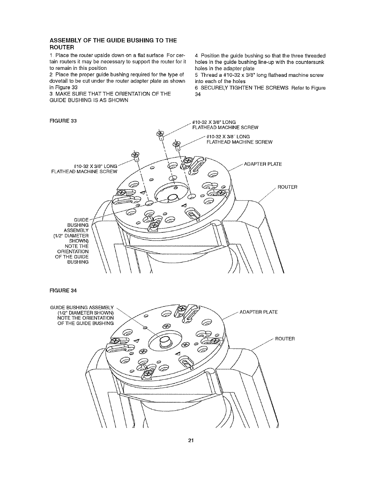
ASSEMBLY OF THE GUIDE BUSHING TO THE
ROUTER
1 Place the router upside down on a flat surface For cer-
tain touters it may be necessary to support the router for it
to remain in this position
2 Place the proper guide bushing required for the type of
dovetail to be cut under the router adapter plate as shown
in Figure 33
3MAKE SURE THAT THE ORIENTATION OF THE
GUIDE BUSHING IS AS SHOWN
4 Position the guide bushing so that the three threaded
holes in the guide bushing line-up with the countersunk
holes in the adapter plate
5 Thread a#10-32 x 3/8" long flathead machine screw
into each of the holes
6 SECURELY TIGHTEN THE SCREWS Refer to Figure
34
FIGURE 33
#10-32 X 3/8" LONG_
FLATHEAD MACHINE SCREW
_/ /#10-32 X 3/8" LONG
\ _J FLATHEAD MACHINE SCREW
ADAPTER PLATE
/ROUTER
s/
/
GUt0
BUSH1NG
ASSEMBLY
(1/2" DIAMETER
SHOWN)
NOTE THE
ORIENTATION
OFTHE GUIDE
BUSHING
FIGURE 34
GUIDE BUSHING ASSEMBLY
(1/2" DIAMETER SHOWN) "_
NOTE THE ORIENTATION
OFTHE GUIDE BUSHING
ROUTER
2t
[J_"]"m_WARNING' THE DOVETAIL JiG MUST ALWAYS
BE FIRMLY AND SECURELY MOUNTED TO A SOLID
AND FIRM WORK SURFACE, SUCH AS A WORK-
BENCH, BEFORE USE FAILURE TO DO SO COULD
CAUSE THE DOVETAIL JIG TO TIP OVER OR SLIDE
ALONG THE WORK SURFACE, RESULTING IN PROP-
ERTY DAMAGE AND SERIOUS PERSONAL INJURY
MOUNTING THE DOVETAIL JIG TO A WORK SURFACE
OR WORKBENCH USING CLAMPS
USING THIS MOUNTING METHOD ALLOWS YOU TO
MOUNT THE DOVETAIL JIG SO THAT IT CAN BE EASF
LY INSTALLED, FOR USE, AND REMOVED, FOR STOR_
AGE, WITHOUT PERMANENTLY TAKING UP SPACE ON
YOUR WORKBENCH
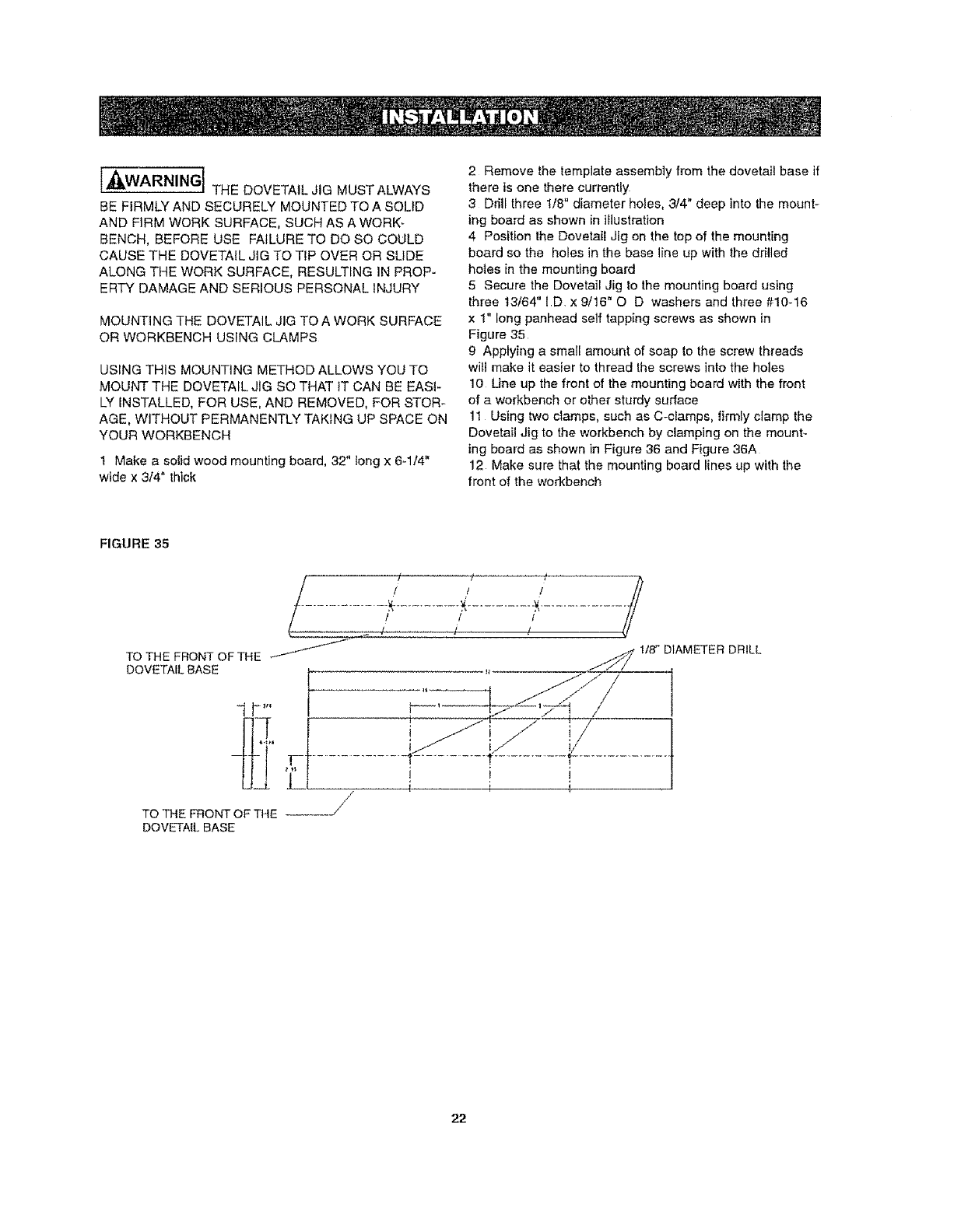
1 Make a solid wood mounting board, 32" long x 6-1/4"
wide x 3/4" thick
2 Remove the template assembly from the dovetail base if
there is one there currently
3 Ddll three 1/8" diameter holes, 3/4" deep into the mount-
ing board as shown in illustration
4 Position the Dovetail Jig on the top of the mounting
board so the holes in the base line up with the drilled
holes in the mounting board
5 Secure the Dovetail Jig to the mounting board using
three t3/64" I.D. x 9/16" O D washers and three #10-16
x 1" long panhead self tapping screws as shown in
Figure 35
g Applying a small amount of soap to the screw threads
will make it easier to thread the screws into the holes
10 Line up the front of the mounting board with the front
of a workbench or other sturdy surface
11 Using two clamps, such as C-clamps, firmly clamp the
Dovetail ,Jig to the workbench by clamping on the mount-
ing board as shown in Figure 36 and Figure 36A
12 Make sure that the mounting board lines up with the
front of the workbench
FIGURE 35
_/ // / //2
TO THE FRONT OF THE ,_"_'_ ,_ 1/8" DIAMETER DRILL
DOVETAIL BASE
TO THE FRONT OF THE .....
DOVETAIL BASE
_ i
//
22
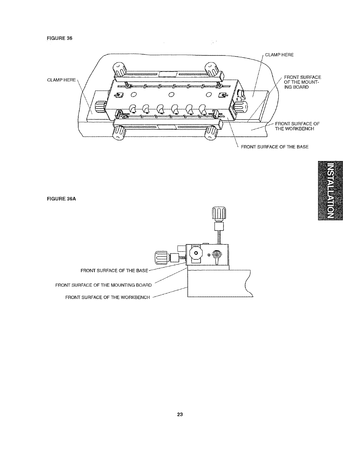
FIGURE 36
CLAMP HERE
CLAMP HERE
FRONT SURFACE
OF THE MOUNT-
ING BOARD
FRONT SURFACE OF
THE WORKBENCH
FRONT SURFACE OF THE BASE
FIGURE 36A
FRONT SURFACE OF THE BASE
FRONT SURFACE OF THE MOUNTING BOARD
FRONT SURFACE OF THE WORKBENCH
23
STYLES OF DOVETAIL JOINTS
• Four different styles of dovetail joints can be made with
the Dovetail Jig using your router
• These joints are described in the following sections
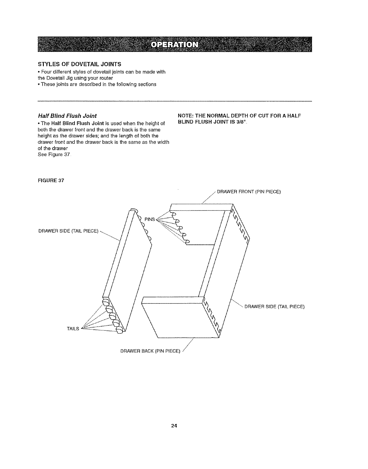
Haft Blind Flush Joint
• The Half Blind Flush Joint is used when the height of
both Ihe drawer front and the drawer back is the same
height as the drawer sides; and the length of both the
drawer front and the drawer back is the same as the width
of the drawer
See Figure 37
NOTE: THE NORMAL DEPTH OF CUT FOR AHALF
BLIND FLUSH JOINT IS 318",
FIGURE 37
/DRAWER FRONT (PiN PIECE)
/
F
DRAWER SIDE (TAIL PIECE)
"_- DRAWER SiDE (TAIL PIECE)
TAILS \
DRAWER BACK (PIN PIECE) /
24
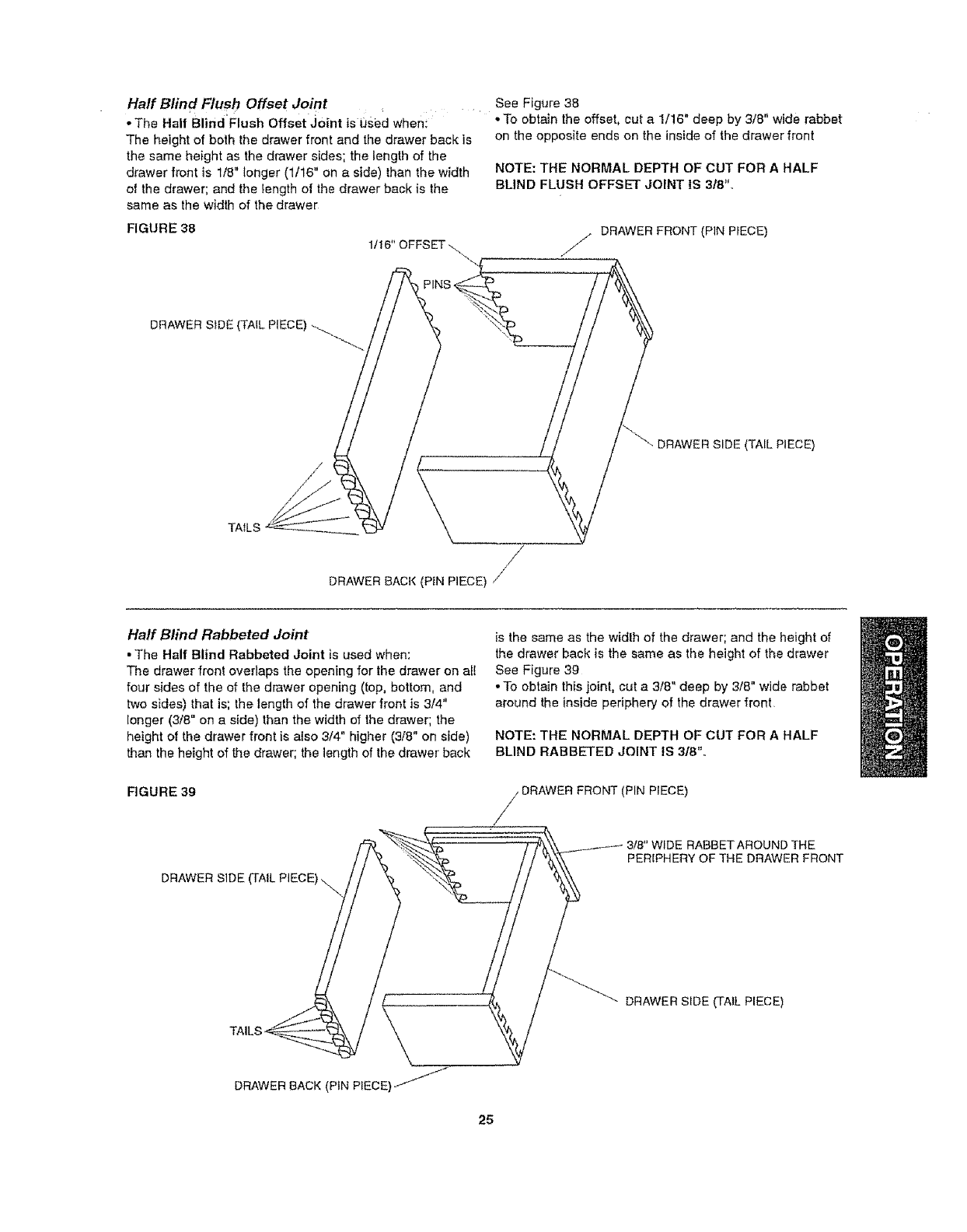
Half Btin d Flush Offset Joint
oThe Half Blind'Flush Offset JOint is used when_
The height of both the drawer front and the drawer back is
the same height as the drawer sides; the length of the
drawer front is 1/8" longer (1/16" on a side) than the width
of the drawer; and the length of the drawer back is the
same as the width of the drawer
FIGURE 38
1/!6" OFFSET ...
See Figure 38
*To obtain the offset, cut a 1/16" deep by 3/8" wide rabbet
on the opposite ends on the inside of the drawer front
NOTE: THE NORMAL DEPTH OF CUT FOR A HALF
BLIND FLUSH OFFSET JOINT IS 3t8".
DRAWER FRONT (PIN PIECE)
DRAWER SIDE (TALLPIECE)
-_RSIDE (TAIL PIECE)
/
DRAWER BACK (PIN PIECE) J
Haft Blind Rabbeted Joint
• The Half Blind Rabbeted Joint is used when:
The drawer fronl overlaps the opening for the drawer on el!
four sides of the of the drawer opening (top, bottom, and
two sides) that is; the length of the drawer front is 3/4"
longer (3/8" on a side) than the width of the drawer; the
height of the drawer front is atso 3/4" higher (3/8" on side)
than the height of the drawer; the length of the drawer back
FIGURE 39
DRAWER SIDE
is the same as the widlh of the drawer; and the height of
the drawer back is the same as the height of the drawer
See Figure 39
•To obtain this joint, cut a 3/8" deep by 3/8" wide rabbet
around the inside periphery of the drawer '_ront
NOTE: THE NORMAL DEPTH OF CUT FOR A HALF
BLIND RABBETED JOINT !S 318'L.
DRAWER FRONT (PIN PIECE)
3/8" WIDE RABBETAROUND THE
PERIPHERY OF THE DRAWER FRONT
TAIL
DRAWER S_DE (TAIL PIECE)
DRAWER BACK (PtN PIECE)
25
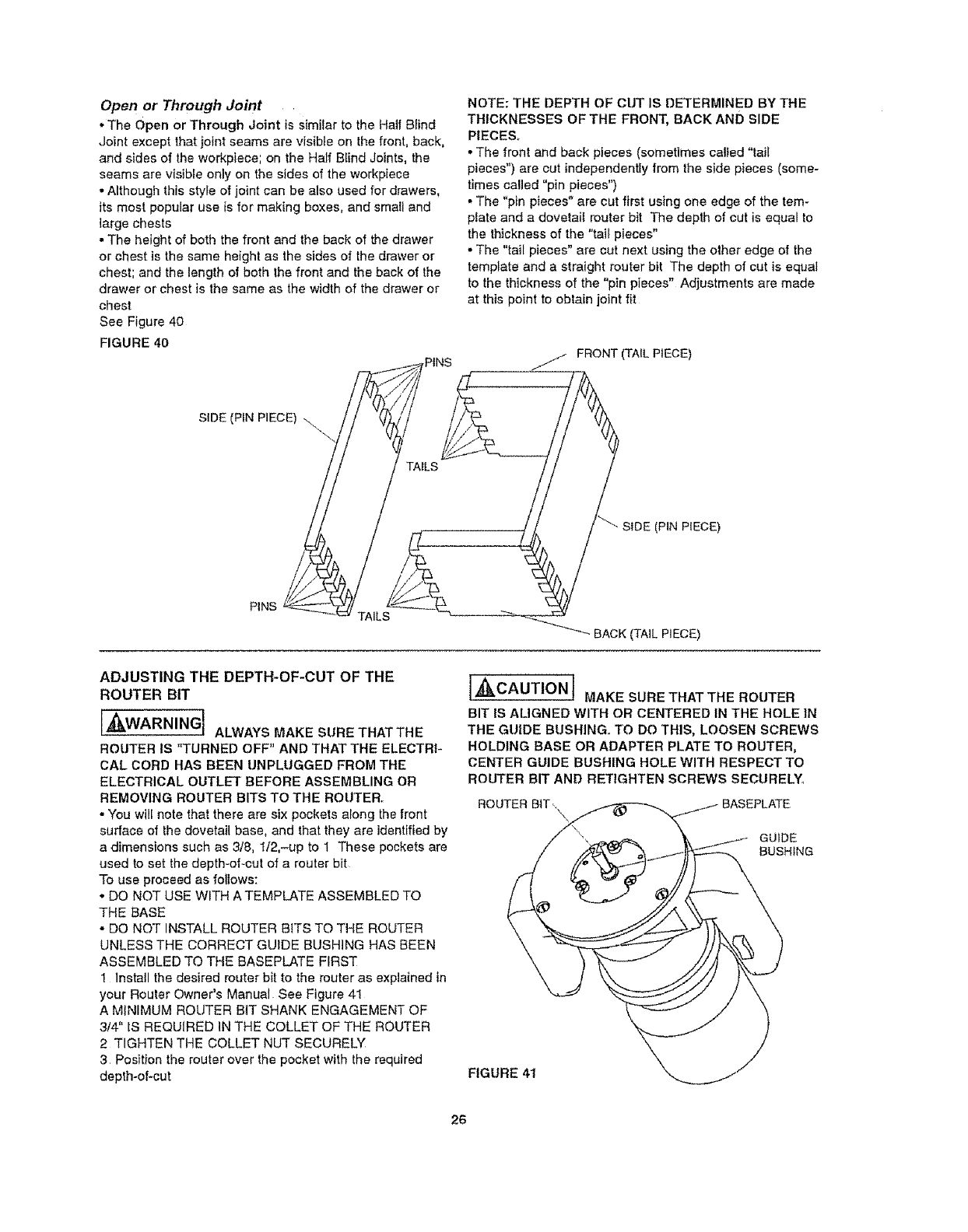
Open or Through Joint
• The Open or Through Joint is similar to the Half Blind
Joint except that joint seams are visible on the front, back,
and sides of the workpiece; on the Half Blind Joints, the
seams are visible only on the sides of the workpiece
•Although this style of joint can be also used for drawers,
its most popular use is for making boxes, and small and
large chests
•The height of both the front and the back of the drawer
or chest is the same height as the sides of the drawer or
chest; and the length of both the front and the back of the
drawer or chest is the same as the width of the drawer or
chest
See Figure 40
FIGURE 40
NOTE: THE DEPTH OF CUT IS DETERMINED BY THE
THICKNESSES OF THE FRONT, BACK AND SIDE
PIECE&
• The front and back pieces (sometimes called "tail
pieces") are cut independentIy from the side pieces (some-
times called "pin pieces")
- The "pin pieces" are cut first using one edge of the tem-
plate and a dovetail router bit The depth of cut is equal to
the thickness of the "tail pieces"
•The "tail pieces" are cut next using the other edge of the
template and a straight router bit The depth of cut is equal
to the thickness of the "pin pieces" Adjustments are made
at this point to oblain joint fit
ADJUSTING THE DEPTH-OF-CUT OF THE
ROUTER BIT
r__ ,t
[,_._,WARNINGJ ALWAYS MAKE SURETHATTHE
ROUTER tS "TURNED OFF" AND THAT THE ELECTRI-
CAL CORDHASBEENUNPLUGGEDFROMTHE
ELECTRICAL OUTLET BEFORE ASSEMBLING OR
REMOVING ROUTER BITS TO THE ROUTER,
• You will note that there are six pockets along the front
surface of the dovetail base, and that they are identified by
a dimensions such as 3/8, lt2,-up to 1 These pockets are
used to set the depth-of-cut of a router bit
To use proceed as follows:
- DO NOT USE WITH A TEMPLATE ASSEMBLED TO
THE BASE
o DO NOT INSTALL ROUTER BITS TO THE ROUTER
UNLESS THE CORRECT GUIDE BUSHING HAS BEEN
ASSEMBLED TO THE BASEPLATE FIRST
1 Install the desired router bit to the router as explained in
your Router Owner's Manual See Figure 41
A MINIMUM ROUTER BIT SHANK ENGAGEMENT OF
3/4" IS REQUIRED IN THE COLLET OF THE ROUTER
2 TIGHTEN THE COLLET NUT SECURELY
3 Position the router over the pocket with the required
depth-of-cut
I_CAUTION i MAKE SURE THAT THE ROUTER
BIT ISALIGNED WITH OR CENTERED IN THE HOLE IN
THE GUIDE BUSHING. TO DO THIS, LOOSEN SCREWS
HOLDING BASE OR ADAPTER PLATE TO ROUTER,
CENTER GUIDE BUSHING HOLE WITH RESPECT TO
ROUTER BIT AND RETtGHTEN SCREWS SECURELY_
ROUTER BIT ,, BASEPLATE
GUIDE
BUSHING
FIGURE 41
26
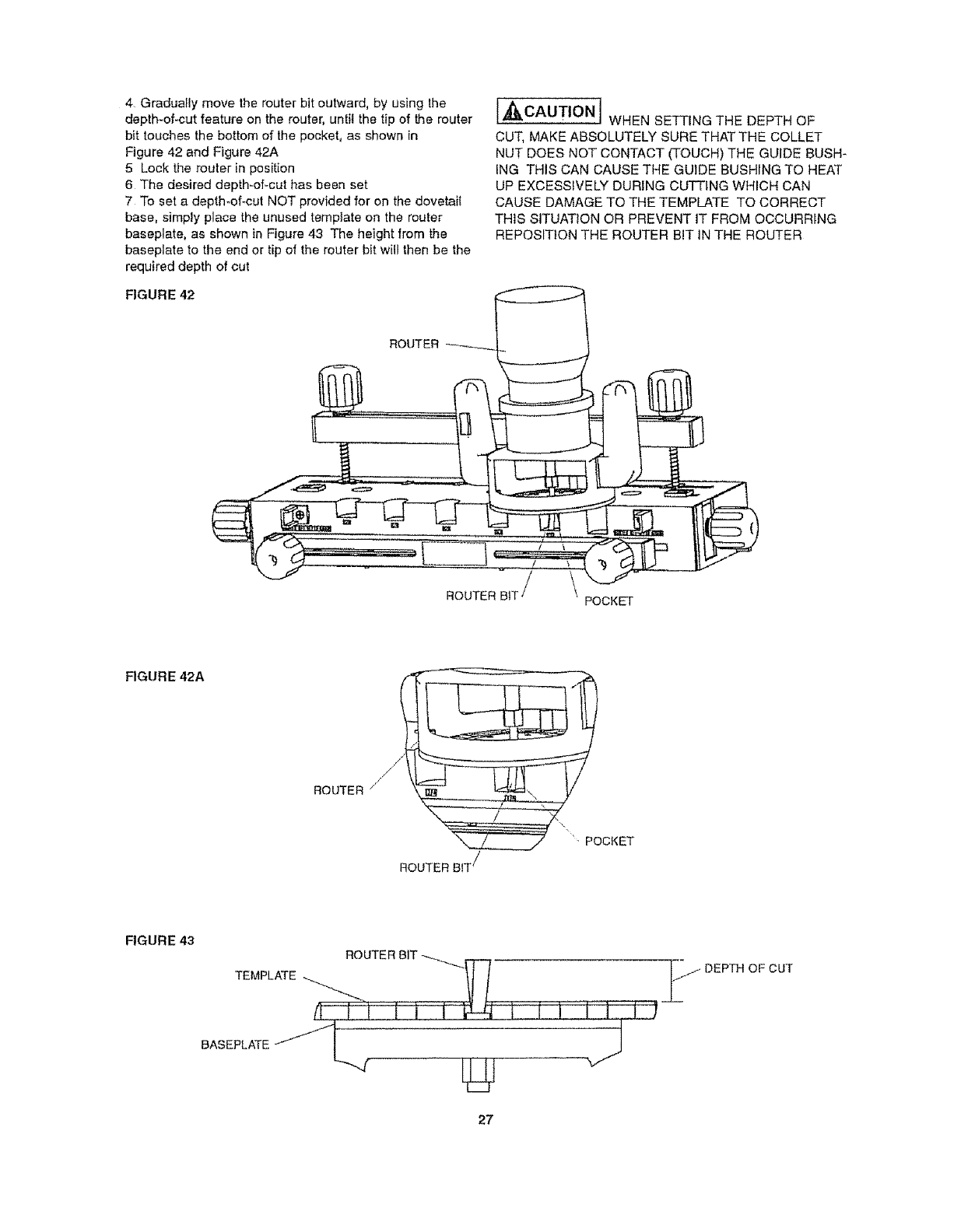
4 Gradually move the router bit outward, by using the
depth-of-cut feature on the router, until the tip of the router
bit touches the bottom of the pocket, as shown in
Figure 42 and Figure 42A
5 Lock the router in position
6 The desired depth-of-cut has been set
7 To set a depth-of-cut NOT provided for on the dovetail
base, simply place the unused template on the router
baseplate, as shown in Figure 43 The height _rom the
baseplate to the end or tip of the router bit will then be the
required depth of cut
FIGURE 42
l,t_ II_._,CAUTION i WHEN SETTING THE DEPTH OF
CUT, MAKE ABSOLUTELY SURE THAT THE COLLET
NUT DOES NOT CONTACT (TOUCH) THE GUIDE BUSH-
ING THIS CAN CAUSE THE GUIDE BUSHING TO HEAT
UP EXCESSIVELY DURING CUTTING WHICH CAN
CAUSE DAMAGE TO THE TEMPLATE TO CORRECT
THIS SITUATION OR PREVENT IT FROM OCCURRING
REPOSITtON THE ROUTER BIT IN THE ROUTER
ROUTER
ROUTER BIT \ POCKET
FIGURE 42A
ROUTER
ROUTER BIT /
'" POCKET
FIGURE 43
TEMPLATE ti I 1' --j OEPT.O CUT
27
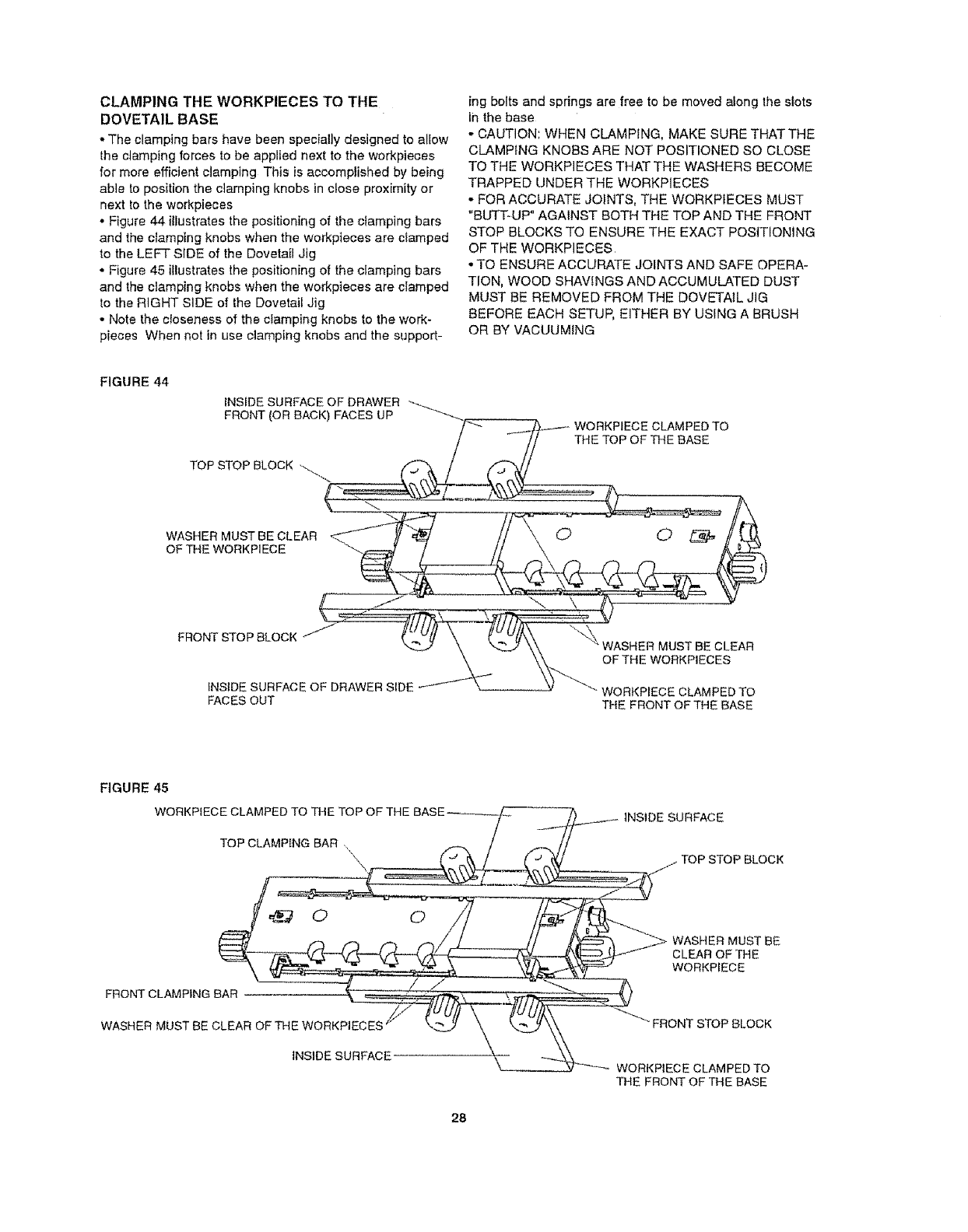
CLAMPING THE WORKPIECES TO THE
DOVETAIL BASE
-The clamping bars have been specially designed to allow
lhe clamping forces to be applied next to the workpieces
for more efficient clamping This is accomplished by' being
able to position the clamping knobs in close proximity or
next to the workpieces
• Figure 44 illustrates the positioning of the ctamping bars
and the clamping knobs when the workpieces are clamped
to the LEFT SiDE of the Dovetail Jig
• Figure 45 illustrates the positioning of the clamping bars
and the clamping knobs when the workpieces are clamped
to the RIGHT SIDE of the Dovetail Jig
- Note the closeness of the clamping knobs to the work-
pieces When not in use etamping knobs and the support-
ing bolts and springs are free to be moved atong the slots
in the base
• CAUTION: WHEN CLAMPING, MAKE SURE THAT THE
CLAMPING KNOBS ARE NOT POSITIONED SO CLOSE
TO THE WORKPIECES THAT THE WASHERS BECOME
TRAPPED UNDER THE WORKPIECES
,, FOR ACCURATE JOINTS, THE WORKPIECES MUST
"BUTT-UP" AGAINST BOTH THE TOP AND THE FRONT
STOP BLOCKS TO ENSURE THE EXACT POSITIONING
OF THE WORKPIECES
• TO ENSURE ACCURATE JOINTS AND SAFE OPERA-
TION, WOOD SHAVINGS AND ACCUMULATED DUST
MUST BE REMOVED FROM THE DOVETAIL JIG
BEFORE EACH SETUP, EITHER BY USING A BRUSH
OR BY VACUUMING
FIGURE 44
INSIDE SURFACE OF DRAWER
FRONT (OR BACK) FACES UP _ .._._._,----_ WORKPIECE CLAMPED TO
// THE TOP OF THE BASE
TOP STOP BLOCK ,_.._. _y
LEAR
(
OF HEV,O.KP,ECES
,Ns,oESUBFAOEOF°RAWERS'DE WORKPIECEC.AMPEOTO
FAOESO0 T,-,EFRONTOFT.EBASE
FIGURE 45
WORKPfECE CLAMPED TO THE TOP OF THE
TOP CLAMPING BAR.,
iNSIDE SURFACE
• TOP STOP BLOCK
FRONT CLAMPING BAR
WASHER MUST BE CLEAR OF THE WORKPIECES "_/
INSIDE SURFACE
WASHER MUST BE
CLEAR OF THE
WORKPIECE
FRONT STOP BLOCK
WORKPIECE CLAMPED TO
THE FRONT OF THE BASE
28
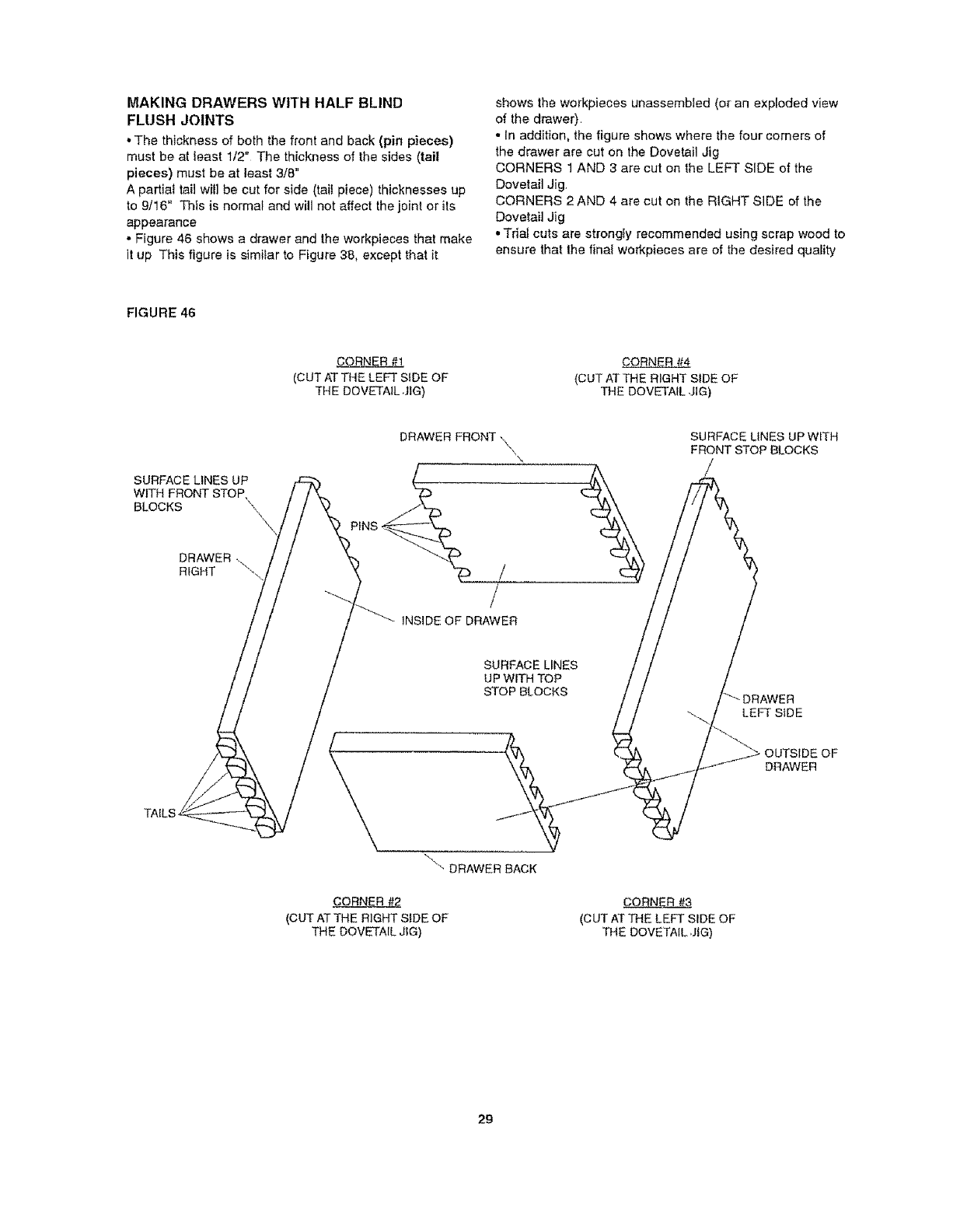
MAKING DRAWERS WITH HALF BLIND
FLUSH JOINTS
•The thickness of both the front and back (pin pieces)
must be at least 1/2" The thickness of the sides (tail
pieces) must be at least 3/8 _
A partial tail will be cut for side (tai! piece) thicknesses up
to 9/16" This is norma_ and will not affect the joint or its
appearance
o Figure 46 shows a drawer and the workpieces that make
it up This figure is similar to Figure 38, except that it
shows the workpieces unassembled (or an exploded view
of the drawer)
• In addition, the figure shows where the four comers of
the drawer are cut on the Dovetail Jig
CORNERS 1 AND 3 are cut on the LEFT SIDE of the
Dovetail Jig
CORNERS 2AND 4 are cut on the RIGHT SIDE of the
Dovetail Jig
• TdaJ cuts are strongly recommended using scrap wood to
ensure that the final workpieces are of the desired quality
FIGURE 46
CORNER #1
(CUT AT THE LEFT SIDE OF
THE DOVETAIL ,JIG) (CUT AT THE RIGHT SIDE OF
THE DOVETAIL ,JIG)
SURFACE LINES UP
WITH FRONT STOP,
BLOCKS \,\H
DRAWER .\
RIGHT ",
DRAWER FRONT -\
/
/
INSIDE OF DRAWER
SURFACE LINES UP WITH
FRONT STOP BLOCKS
/
SURFACE LINES
UP WITH TOP
STOP BLOCKS
-\ "- DRAWER BACK
CORNER
(CUT AT THE RIGHT SIDE OF
THE DOVETAIL JIG)
(CUT AT THE LEFT SIDE OF
TIDE DOVETAIL ,JIG)
LEFT SiDE
OUTSIDE OF
DRAWER
29
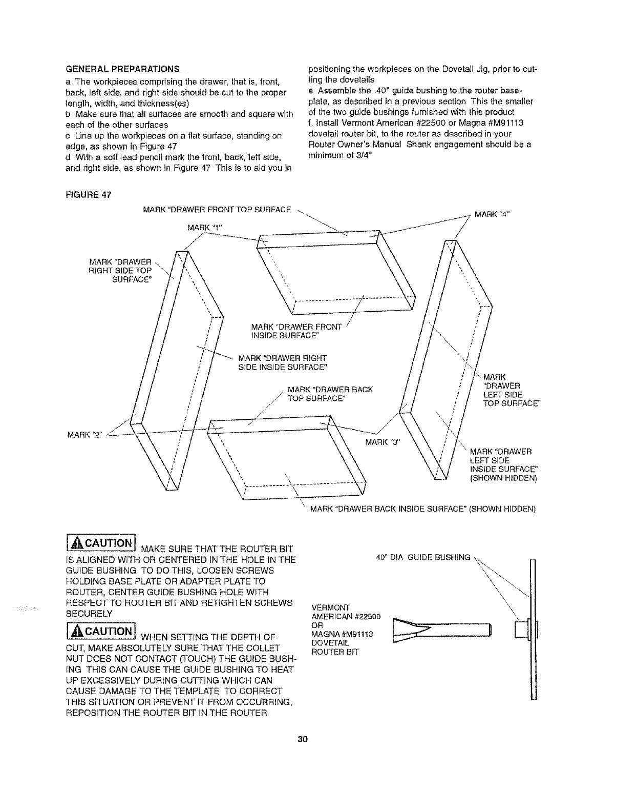
GENERALPREPARATIONS
a Theworkpiecescomprisingthedrawer,that is, front,
back, ]eft side, and right side should be cut to the proper
length, width, and thickness(es)
b Make sure that all surfaces are smooth and square with
each of the other surfaces
c Line up the workpieces on a flat surface, standing on
edge, as shown in Figure 47
d With a soft lead pencil mark the front, back, left side,
and right side, as shown in Figure 47 This is to aid you in
positioning the workpieces on the Dovetail Jig, prior to cut-
ting the dovetails
e Assemble the 40" guide bushing to the router base-
plate, as described in a previous section This the smaller
of the two guide bushings furnished with this product
flnslall Vermont American #22500 or Magna #Mg 1113
dovetail router bit, to the router as described in your
Router Owner's Manual Shank engagement should be a
minimum of 3/4"
FIGURE 47
MARK "DRAWER FRONT TOP SURFAC E . MARK 'W"
MARK "1" _ _.._.._'-I'"_/_
MARK "DRAWER \ __
RIGHTSIDE TOP \. \ ",, \ \
"'" MARK
INSIDE SURFACE"
MARK
/MARK "DRAWER RIGHT
/SIDE _NSIDE SURFACE" r
;;. MARK
/MARt{ "DRAWER BACK '"DRAWER
; .,,,-" ,' LEFT SIDE
, I TOP SURFACE"
\ MARK "DRAWER
", LEFT SIDE
", INSIDE SURFACE"
'. \ (SHOWN HIDDEN)
\\MARK "DRAWER BACK INSIDE SURFACE" (SHOWN HIDDEN)
IAII, CAUT!ONIMAKE SURE THATTHE ROUTER BiT
IS ALIGNED WITH OR CENTERED IN THE HOLE tN THE
GUIDE BUSHING TO DO THIS, LOOSEN SCREWS
HOLDING BASE PLATE OR ADAPTER PLATE TO
ROUTER, CENTER GUIDE BUSHING HOLE WtTH
RESPECT TO ROUTER BIT AND RETIGHTEN SCREWS
SECURELY
] CAUTION/ WHENSETTING7HEDEPTHOF
CUT, MAKE ABSOLUTELY SURE THAT THE COLLET
NUT DOES NOT CONTACT (TOUCH) THE GUIDE BUSH-
ING THIS CAN CAUSE THE GUIDE BUSHING TO HEAT
UP EXCESSIVELY DURING CUTTING WHICH CAN
CAUSE DAMAGE TO THE TEMPLATE TO CORRECT
THIS SITUATION OR PREVENT it FROM OCCURRING,
REPOSITtON THE ROUTER BIT IN THE ROUTER
40" DIA GUIDE BUSHfNG ,_,,
VERMONT
AMERICAN #22500
OR
MAGNA #M911 !3
DOVETAIL
ROUTER BIT
\\\
E
30
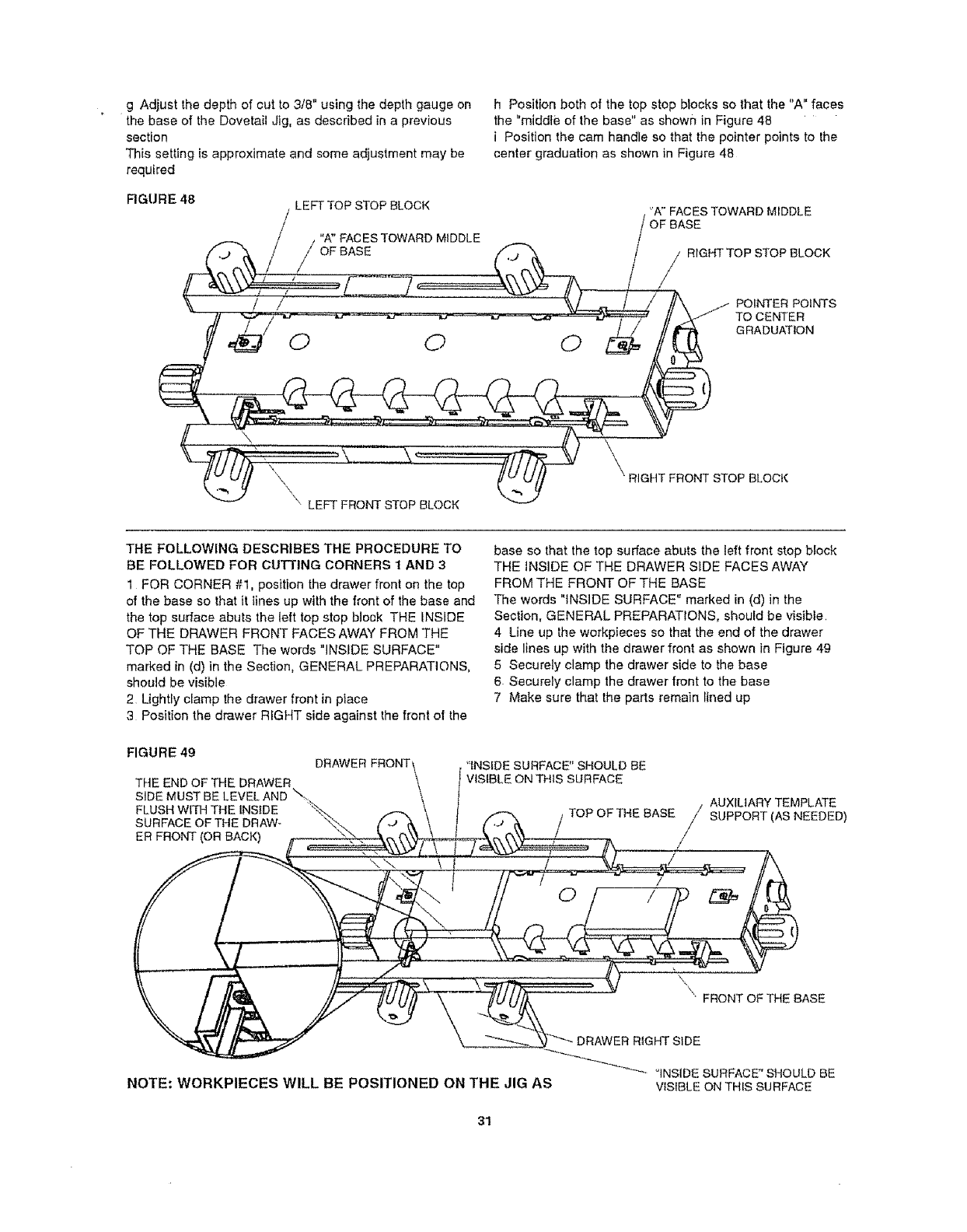
gAdjustthedepthofcutto3/8"usingthedepthgaugeon
thebaseoftheDovetailJig,asdescribedinaprevious
section
Thissettingisapproximateandsomeadjustmentmaybe
required
h Positionbothofthetopstopblockssothatthe"A"faces
the"middleofthebase"asshowninFigure48 '
i Positionthecamhandlesothatthepointerpointstothe
centergraduationasshowninFigure48
FIGURE48 LEFTTOPSTOPBLOCK 'A"FACESTOWARDMIDDLE
OFBASE
."A" FACES TOWARD MIDDLE
_OFB___ASE _ /RIGHT TOP STOP BLOCK
/- ....... 7_------------_-\\V,_ 1A_ /
I
//_/ POINTER POINTS
'It _./ TO CENTER
___ !'[i"V_',","'_ii]ii_, ,/_ _RIGHT FRONT STOP BLOCK
"\ LEFT FRONT STOP BLOCK \ _"'_
THE FOLLOWING DESCRIBES THE PROCEDURE TO
BE FOLLOWED FOR CUTTING CORNERS 1 AND 3
1 FOR CORNER #1, position the drawer front on the top
of the base so that it lines up with the front of the base and
the top surface abuts the left top stop block THE INSIDE
OF THE DRAWER FRONT FACES AWAY FROM THE
TOP OF THE BASE The words "INSIDE SURFACE"
marked in (d) in the Section, GENERAL PREPARATIONS,
should be visible
2 Ughtly clamp the drawer front in place
3Position the drawer RIGHT side against the front of the
base so that the top surface abuts the left front stop block
THE INSIDE OF THE DRAWER S_DE FACES AWAY
FROM THE FRONT OF THE BASE
The words "INSIDE SURFACE" marked in (d) in the
Section, GENERAL PREPARATIONS, should be visible.
4 Line up the workpieces so that the end of the drawer
side lines up with the drawer front as shown in Figure 49
5 Securely clamp the drawer side to the base
6 Securely clamp the drawer front to the base
7 Make sure that the parts remain lined up
FIGURE 49 DRAWER FRONT
THE END OF THE DRAWER
SIDE MUST BE LEVEL AND \-._%
FLUSH WITH THE INSIDE "_,.
SURFACE OF THE DRAW_ %.,
ER FRONT (OR BACK)
'tNSfDE SURFACE" SHOULD BE
VISIBLE ON THIS SURFACE
AUXILIARY TEMPLATE
TOP OFTHE BASE/' SUPPORT (AS NEEDED)
\" FRONT OF THE BASE
DRAWER RIGHT SIDE
"INSIDE SURFACE" SHOULD BE
NOTE: WORKPIECES WILL BE POSITIONED ON THE JIG AS VISIBLE ONTHIS SURFACE
31
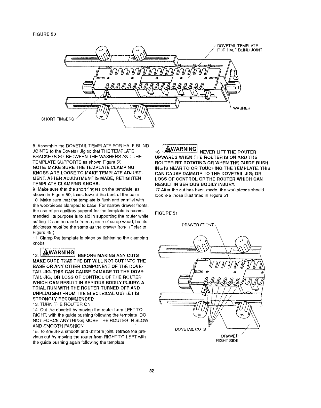
FIGURE5O
/DOVETAIL TEMPLATE
/" FOR HALF BLIND JOINT
/
//
(WASHER
8 Assembfe the DOVETAIL TEMPLATE FOR HALF BLIND
JOINTS to the Dovetait Jig so that THE TEMPLATE
BRACKETS FiT BETWEEN THE WASHERS AND THE
TEMPLATE SUPPORTS as shown Figure 50
NOTE: MAKE SURE THE TEMPLATE CLAMPING
KNOBS ARE LOOSE TO MAKE TEMPLATE ADJUST-
MENT, AFTER ADJUSTMENT IS MADE, RETtGHTEN
TEMPLATE CLAMPING KNOBS.
9 Make sure that the short fingers on the template, as
shown in Figure 50, faces toward the front of the base
10 Make sure that the template is flush and parallel with
the workpieces clamped to base Far narrow drawer fronts,
the use of an auxiliary support for the template is recom-
mended Its purpose is to aid in supporting the router while
cutting It can be made from a piece of scrap wood; but its
thickness must be the same as the drawer front (Refer to
Figure 49)
11 Clamp the temptate in place by tightening the clamping
knobs
12 I'_WARNINGI BEFORE MAKING ANY CUTS
MAKE SURE THAT THE BIT WILL NOT CUT INTO THE
BASE OR ANY OTHER COMPONENT OF THE DOVE-
TAIL JIG,, THIS CAN CAUSE DAMAGE TO THE DOVE-
TAIL JIG; OR LOSS OF CONTROL OF THE ROUTER
WHICH CAN RESULT IN SERIOUS BODILY INJURY,, A
TRIAL RUN WITH THE ROUTER TURNED OFF AND
UNPLUGGED FROM THE ELECTRICAL OUTLET IS
STRONGLY RECOMMENDED°
13 TURN THE ROUTER ON
14 Cut the dovetail by moving the router from LEFTTO
RIGHT, with the guide bushing fol!owing the template DO
NOT FORCE ANYTHING; MOVE THE ROUTER IN SLOW
AND SMOOTH FASHION
15 To ensure a smooth and uniform joint, retrace the pre-
vious cut by moving the router from RIGHT TO LEFT with
the guide bushing again fo_$owing the template
t6 _'_')L],,M,WARNING,NEVER LIFT THE ROUTER
UPWARDS WHEN THE ROUTER IS ON AND THE
ROUTER BIT ROTATING OR WHEN THE GU|DE BUSH-
ING IS NEAR TO OR TOUCHING THE TEMPLATE° THIS
CAN CAUSE DAMAGE TO THE DOVETAIL JIG; OR
LOSS OF CONTROL OF THE ROUTER WHICH CAN
RESULT IN SERIOUS BODILY INJURY,,
17 After the cut has been made, the workpieces should
look like those illustrated in Figure 51
FIGURE 51
DRAWER
DOVETAIL CUTS /
DRAWER /
RIGHT SIDE
32
18 Remove the workpieces from the Dovetail ,Jig and
check how the workpieces fit together Some adjustments
may be required
Refer to the section TROUBLESHOOTING on page 37
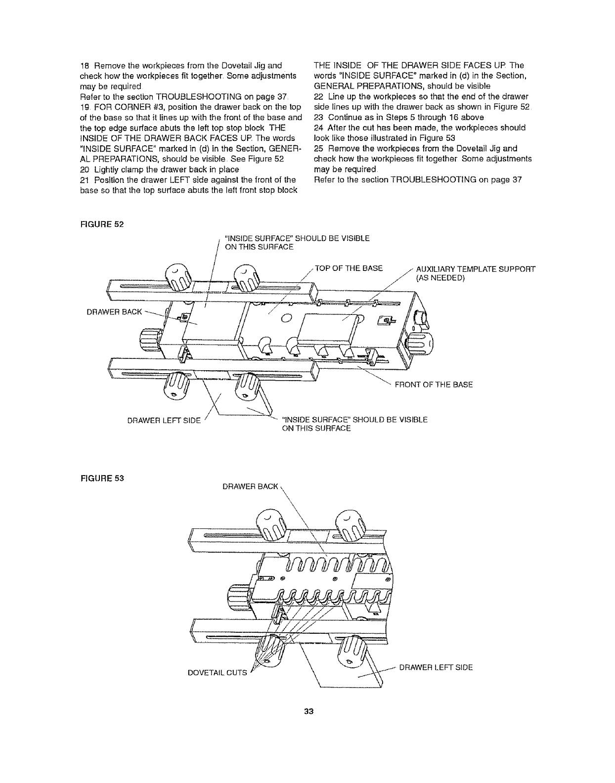
19 FOR CORNER #3, position the drawer back on the top
of the base so that it lines up with the front of the base and
the top edge surface abuts the left top stop block THE
INSIDE OF THE DRAWER BACK FACES UP The words
"INSIDE SURFACE" marked in (d) in the Section, GENER-
AL PREPARATIONS, should be visible See Figure 52
20 Lightly clamp the drawer back in place
21 Position the drawer LEFT side against the front of the
base so that the top surface abuts the left front stop block
THE INSIDE OF THE DRAWER SIDE FACES UP The
words "INSIDE SURFACE" marked in (d) in the Section,
GENERAL PREPARATIONS, should be visible
22 Line up the workpieces so that the end of the drawer
side lines up with the drawer back as shown in Figure 52
23 Continue as in Steps 5 through 16 above
24 After the cut has been made, the workpieces should
took like those illustraied in Figure 53
25 Remove the workpieces from the Dovetail Jig and
check how the workpieces fit together Some adjustments
may be required
Refer to the section TROUBLESHOOTING on page 37
FIGURE 52
I _,'_INSIDESURFACE" SHOULD BE VISIBLE
ON THIS SURFACE
/TOP OF THE BASE /AUXILIARY TEMPLATE SUPPORT
// _ (AS NEEDED)
// ..... .... •
DF_A"AER LEFT SiDE /__"" "INSIDE SURFACE" SHOULD BE VISIBLE
ON THIS SURFACE
FIGURE 53
DRAWER BACK \
DOVETAIL DRAWER LEFT SIDE
33
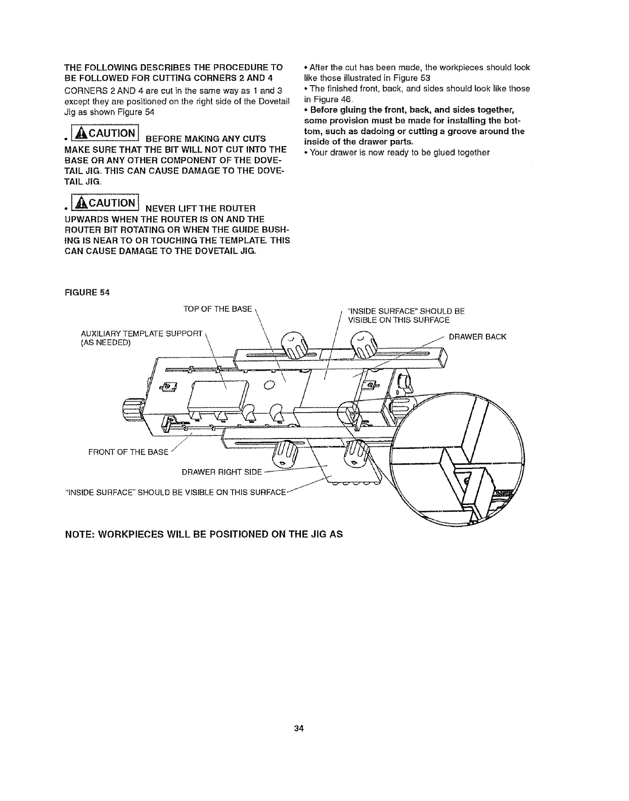
THEFOLLOWINGDESCRIBESTHEPROCEDURETO
BEFOLLOWEDFORCUTTINGCORNERS2AND4
CORNERS2AND4arecutinthesamewayas1and3
except they are positioned on the right side of the Dovetail
Jig as shown Figure 54
.[,_CAUTION I BEFORE MAKING ANY CUTS
MAKE SURE THAT THE BIT WILL NOT CUT INTO THE
BASE OR ANY OTHER COMPONENT OF THE DOVE-
TAIL JIG,, THIS CAN CAUSE DAMAGE TO THE DOVE-
TAIL JIG,,
•I"_cAUTION tNEVER LIFT THE ROUTER
UPWARDS WHEN THE ROUTER IS ON AND THE
ROUTER BIT ROTATING OR WHEN THE GUIDE BUSH-
ING IS NEAR TO OR TOUCHING THE TEMPLATE° THIS
CAN CAUSE DAMAGE TO THE DOVETAIL JIG.
•After the cut has been made, the workpieces should fook
Iike those illustrated in Figure 53
•The finished front, back, and sides should look iike those
in Figure 46
•Before gluing the front, back, and sides together,
some provision must be made for installing the bot-
tom, such as dadoing or cutting a groove around the
inside of the drawer parts°
•Your drawer is now ready to be glued together
FIGURE 54
TOP OF THE BASE \
\
AUXILIARY(AsNEEDED)TEMPLATESUPPORT \\ _\
'INSIDE SURFACE" SHOULD BE
VISIBLE ON THIS SURFACE
DRAWER BACK
/
/
FRONT OF THE BASE "/
DRAWER RIGHT SIDE
"iNSIDE SURFACE" SHOULD BE VrSIBLE ON THIs SURFACE
NOTE: WORKPIECES WILL BE POSITIONED ON THE JIG AS
34
MAKING DRAWERS WITH HALF BLIND FLUSH
OFFSET JOINTS
GENERAL PREPARATIONS
a The iength of the drawer front is 1/8" Ionger than the
length of the drawer back
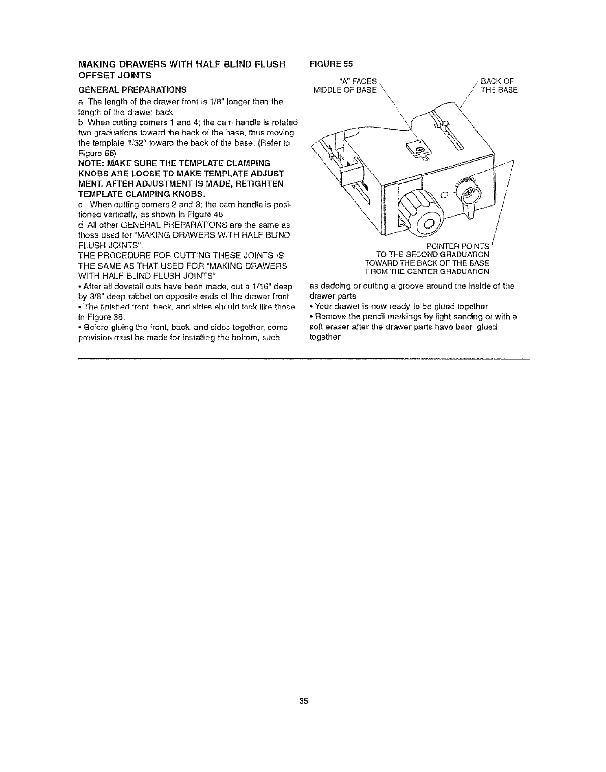
b When cutting comers 1 and 4; the cam handle is rotated
two graduations toward the back of the base, thus moving
the template !/32" toward the back of the base (Refer to
Figure 55)
NOTE: MAKE SURE THE TEMPLATE CLAMPING
KNOBS ARE LOOSE TO MAKE TEMPLATE ADJUST-
MENT, AFTER ADJUSTMENT IS MADE, RE'TIGHTEN
TEMPLATE CLAMPING KNOBS,
c When cutting corners 2 and 3; the cam handle is posi-
tioned vertically, as shown in Figure 48
d All other GENERAL PREPARATIONS are the same as
those used for "MAKING DRAWERS WITH HALF BLfND
FLUSH JOtNTS"
THE PROCEDURE FOR CUTTING THESE JOINTS IS
THE SAME AS THAT USED FOR "MAKING DRAWERS
WITH HALF BLIND FLUSH JOINTS"
•After aI1 dovetail cuts have been made, cut a 1/16" deep
by 3/8" deep rabbet on opposite ends of the drawer front
• The finished front, beck, and sides should look like those
in Figure 38
• Before gluing the front, back, and sides together, some
provision must be made for installing the bottom, such
RGURE 55
"A" FACES \ BACK OF
MIDDLE OF BASE \\ THE BASE
\\
POINTER POINT5
TO THE SECOND GRADUATION
TOWARD THE BACK OF THE BASE
FROM THE CENTER GRADUATION
as dadoing or cutting a groove around the inside of the
drawer parts
o Your drawer is now ready to be glued together
• Remove the pencil markings by light sanding or with a
soft eraser after the drawer parts have been glued
together
35
MAKING DRAWERS WITH HALF BLIND
RABBETED JOINTS
GENERAL PREPARATIONS
a The length of the drawer front is 3/4" longer than the
tength of the drawer back
b The height of the drawer front is 314" higher than the
height of the drawer back and drawer sides
• IT tS EXTREMELY iMPORTANT THAT THE TEMPLATE
BE PROPERLY ALIGNED WHEN MAKING THESE
JOINTS, OR ELSE, IN ADDITION TO THE JOINT SPAC-
iNG NOT BEING EQUAL, AS SHOWN 1N FIGURE 60
BELOW, THE TOP SURFACES OF THE SIDES, FRONT,
AND BACK WILL NOT "LINE-UP" PROPERLY EITHER
REFER TO THE SECTION "ALIGNMENT OF THE TEM-
PLATES" (Figure 60 illustrates a Flush Dovelail Joint)
-All other GENERAL PREPARATIONS, except as noted
below in the procedure, are the same as those used for
"MAKING DRAWERS WITH HALF BLIND FLUSH
J Of NTS"
THE PROCEDURE FOR CUTTING CORNERS 1 AND 4
IS THE SAME AS THAT USED FOR "MAKING DRAW-
ERS WITH HALF BLIND FLUSH JOINTS" EXCEPT
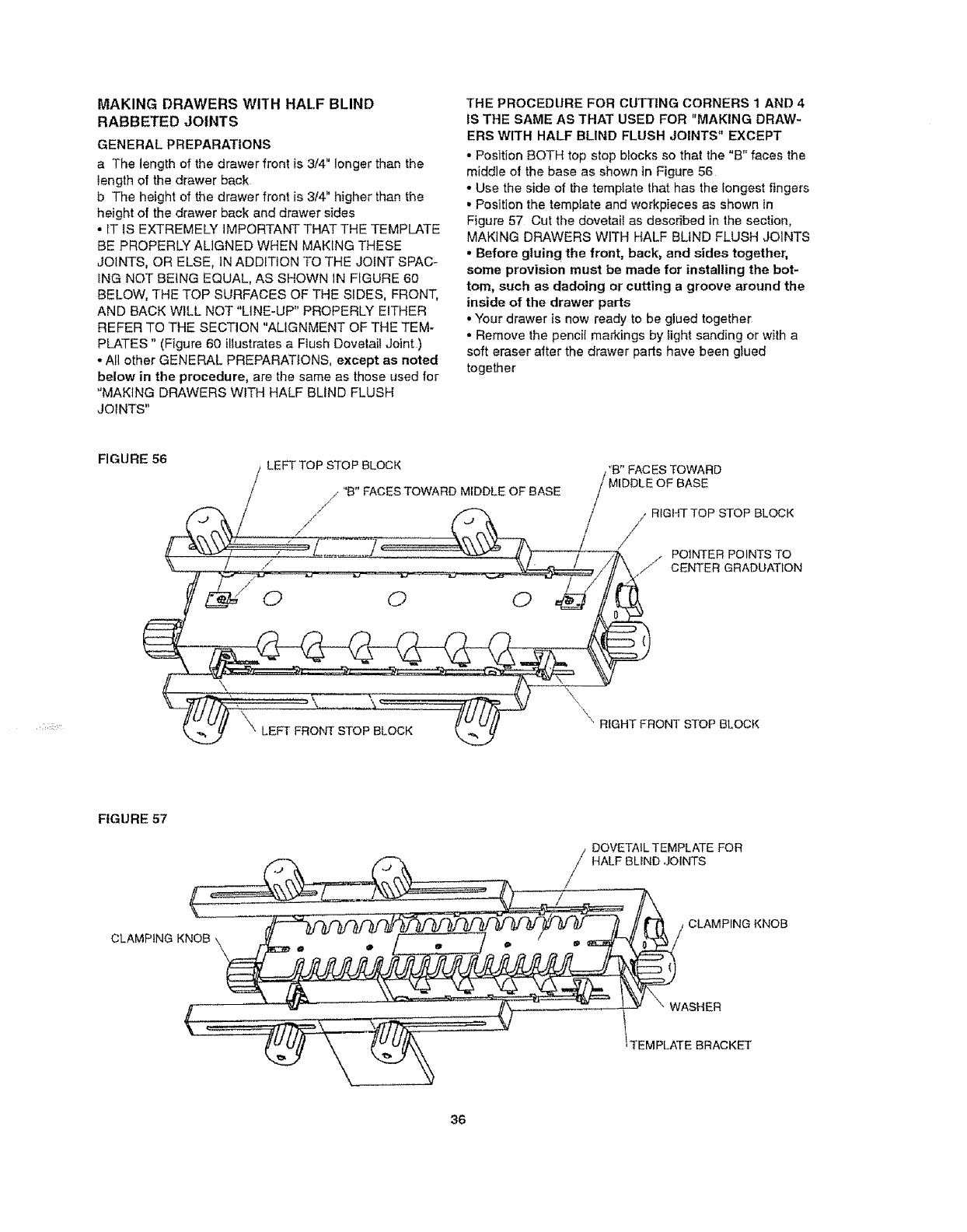
° Position BOTH top stop blocks so that the "B" faces the
middle of the base as shown in Figure 56
° Use the side of the tempiate that has the longest fingers
• Position the template and workpieces as shown in
Figure 57 Cut the dovetail as described in the section,
MAKING DRAWERS WITH HALF BLIND FLUSH JOINTS
•Before gluing the front, back, and sides together,
some provision must be made for installing the bot-
tom, such as dadoing or cutting a groove around the
inside of the drawer parts
• Your drawer is now ready to be glued together
• Remove the penciI markings by fight sanding or with a
soft eraser after the drawer parts have been giued
together
FIGURE 56 LEFT TOP STOP BLOCK
,/"B" FACES TOWARD MIDDLE OF BASE
/-/
'B" FAC ES TOWARD
OF BASE
/RIGHT TOP STOP BLOCK
/
/
/POINTER POINTS TO
CENTER GRADUATION
\"LEFT FRONT STOP BLOCK \ RIGHT FRONT STOP BLOCK
FIGURE 57
/DOVETAIL TEMPLATE FOR
_ .......... /HALF BLlND JOINTS
CLAMP NaKNOa ii--%n - "..... I - Z /it / OLAMPINGK.OB
_ASHER
,_L..__' --m'_._.__---_: ........... _ ..... i .,C,,,
TEMPLATEORAOKET
36
TROUBLESHOOTING
o If the joint is too loose: INCREASE the depth of cut by
INCREASING the amount by which the router bit extends
beyond the baseplate by t/64" to 1/32" and make a trial
cut Continue adjusting until desired joint fit is attained
° If the joint is too tight: DECREASE the depth of cut by
DECREASING the amount by which the router bit extends
beyond the baseplate by 1/64" to 1/32" and make a trial
cut Continue adjusting until desired joint fit is attained
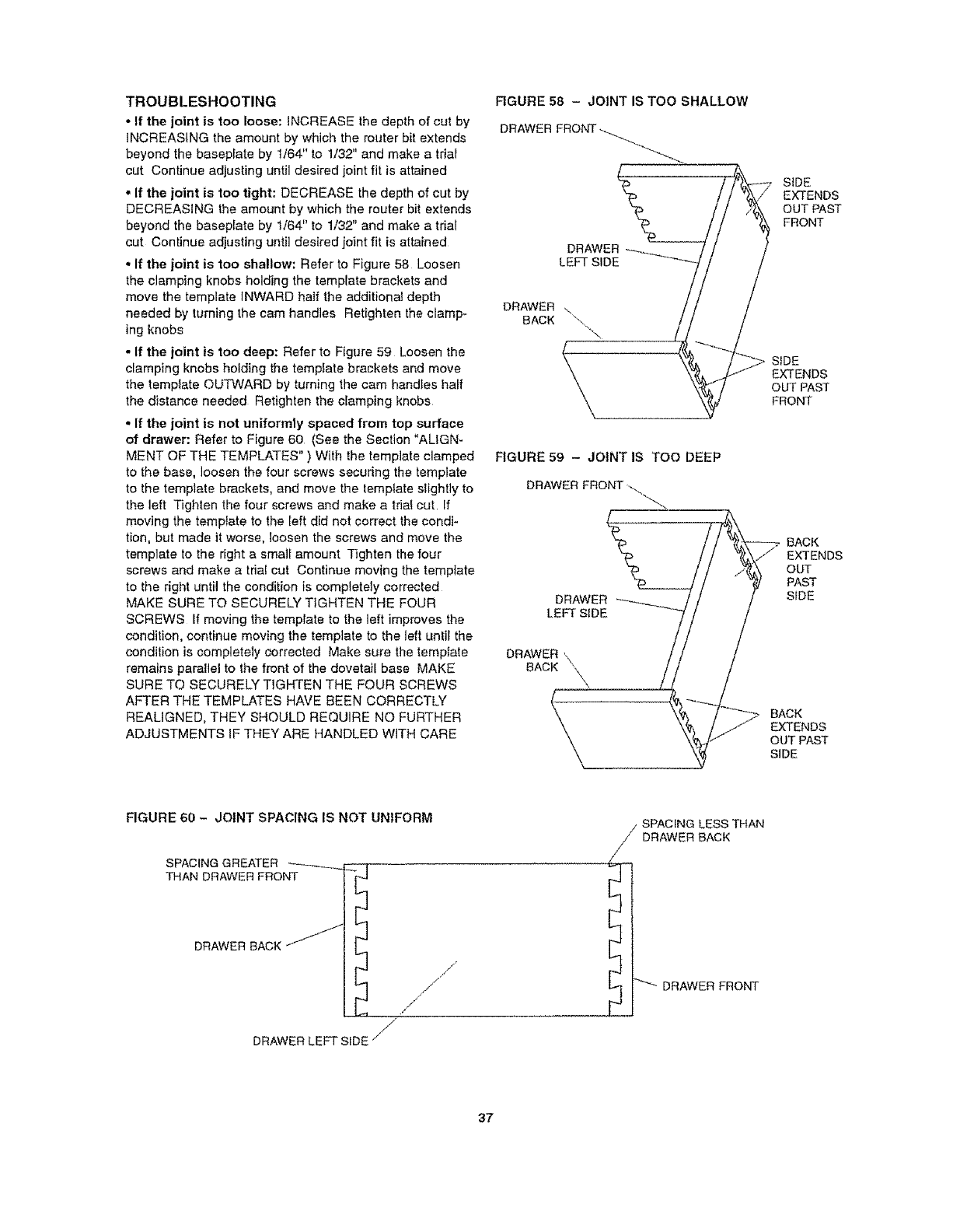
• If the joint is too shallow: Refer to Figure 58 Loosen
the clamping knobs holding the template brackets and
move the template INWARD half the additional deplh
needed by tuming the cam handles Retighten the clamp-
ing knobs
° If the joint is too deep: Refer to Figure 59 Loosen the
clamping knobs holding the template brackets and move
the template OUTWARD by turning the cam handles half
the distance needed Retighten the clamping knobs
° If the joint is not uniformly spaced from top surface
of drawer: Refer to Figure 60 (See the Section "ALIGN-
MENT OF THE TEMPLATES" ) With the template clamped
to the base, loosen the four screws securing the template
to the template brackets, and move the template slightly to
the left Tighten the four screws and make a trial cut if
moving the template to the left did not correct the condi-
tion, but made it worse, loosen the screws and move the
template to the right a small amount Tighten the four
screws and make a trial cut Continue moving the template
to the right until the condition is completely correcled
MAKE SURE TO SECURELY TIGHTEN THE FOUR
SCREWS If moving the template to the left improves the
condition, continue moving the template to the left until the
condifion is completely corrected Make sure the template
remains parallel to the front of the dovetail base MAKE
SURE TO SECURELY TIGHTEN THE FOUR SCREWS
AFTER THE TEMPLATES HAVE BEEN CORRECTLY
REALIGNED, THEY SHOULD REQUIRE NO FURTHER
ADJUSTMENTS IF THEY ARE HANDLED WITH CARE
RGURE 58 - JOINT IS TOO SHALLOW
DRAWER FRONT
DRAWER
BACK
FIGURE 59 - JOINT IS TOO DEEP
DRAWER FRONT ...
DRAWER
LEFT SIDE
DRAWER _\
BACK
_- SIDE
EXTENDS
OUT PAST
FRONT
_SIDE EXTENDS
OUT PAST
FRONT
BACK
EXTENDS
OUT
PAST
SIDE
BACK
EXTENDS
OUT PAST
SIDE
FIGURE 60 - JOINT SPACING IS NOT UNIFORM
SPACING GREATER
THAN DRAWER FRO_ f_l _
DRAWER BACK J'
/
DRAWER LEFT SIDE j
j"
SPACING LESS THAN
DRAWER BACK
DRAWER FRONT
37
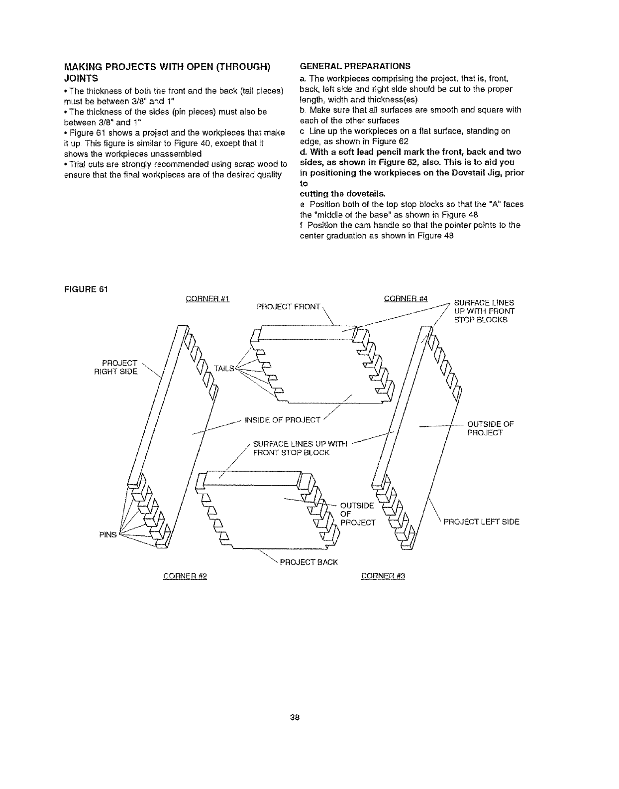
MAKING PROJECTS WITH OPEN (THROUGH)
JOINTS
•The thickness of both the front and the back (tail pieces)
must be between 3/8" and 1"
•The thickness of the sides (pin pieces) must also be
between 3/8" and 1"
•Figure 61 shows a project and the workpieces that make
if up This figure is similar to Figure 40, except that it
shows the workpieces unassembied
• Trial cuts are strongly recommended using scrap wood to
ensure that the final workpieces are of the desired quality
GENERAL PREPARATIONS
a. The workpieces comprising the project, that is, front,
back, left side and right side should be cut to the proper
length, width and thickness(es)
b Make sure that all surfaces are smooth and square with
each of the other surfaces
c Line up the workpieces on a flat surface, standing on
edge, as shown in Figure 62
d.. With asoft lead pencil mark the front, back and two
sides, as shown in Figure 62, also. This is to aid you
in positioning the workpieces on the Dovetail Jig, prior
to
cutting the dovetails.
e Position both of the top stop blocks so that the "A" faces
the "middle of the base" as shown in Figure 48
f Position the cam handle so that the pointer points to the
center graduation as shown in Figure 48
FIGURE 61
PROJECT
RIGHT SIDE
CORNER#1 CORNE_ SURFACE LINES
PROJECT FRONT\ _ UP WITH FRONT
.............. /_ STOP BLOCKS
/yv
//SURFACE LINES UP WITFI
FRONT STOP BLOCK
/
"_--_'-_0 UTSIDE I
OR%EOT
_" PROJECT SACK
-_CTLEFT SIDE
CORNER#_ CORNE_
38
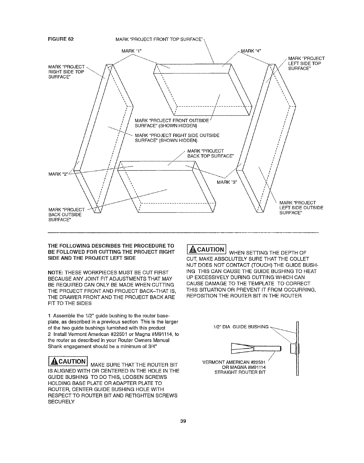
FIGURE 62
MARK
MARK "PROJECT
BACK OUTSIDE
SURFACE"
MARl,( "PROJECT FRONT TOP SURFACE" \
MARl( "1"
MAflK"PROJECTFRONTOUTSIDE t
SURFACE" (SHOWN HIDDEN)
MARt( "PROJECT RIGHT SIDE OUTSIDE
SURFACE" (SHOWN HIDDEN)
MARK"PROJECT
// BACKTOP SURFACE"
/
/MARK "PROJECT
LEFT SIDE TOP
SURFACE"
MARt( "PROJECT
LEFT SIDE OUTSIDE
SURFACE"
THE FOLLOWING DESCRIBES THE PROCEDURE TO
BE FOLLOWED FOR CU_ING THE PROJECT RIGHT
SIDE AND THE PROJECT LEFT SIDE
NOTE: THESE WORKPtECES MUST BE CUT FIRST
BECAUSE ANY JOINT FIT ADJUSTMENTS THAT MAY
BE REQUIRED CAN ONLY BE MADE WHEN CUTTING
THE PROJECT FRONT AND PROJECT BACK-THAT iS,
THE DRAWER FRONTAND THE PROJECT BACK ARE
FIT TO THE SIDES
1 Assembfe the 1/2" guide bushing to the router base-
plate, as described in a previous section This is the larger
of the two guide bushings furnished with this product
2 Install Vermont American #22501 or Magna #Mg1114, to
the router as described in your Router Owners Manual
Shank engagement should be a minimum of 3,/4"
I,_CAUTION 1MAKE SURE THAT THE ROUTER BIT
IS ALIGNED WITH OR CENTERED IN THE HOLE iN THE
GUIDE BUSHING TO DO THIS, LOOSEN SCREWS
HOLDING BASE PLATE OR ADAPTER PLATE TO
ROUTER, CENTER GUIDE BUSHING HOLE WITH
RESPECT TO ROUTER BIT AND RETIGHTEN SCREWS
SECURELY
t._i_lt,_,CAUTtON1 WHEN SETTING THE DEPTH OF
CUT, MAKE ABSOLUTELY SURE THAT THE COLLET
NUT DOES NOT CONTACT (TOUCH)THE GUIDE BUSH-
ING THIS CAN CAUSE THE GUIDE BUSHING TO HEAT
UP EXCESSIVELY DURING CUTTING WHICH CAN
CAUSE DAMAGE TO THE TEMPLATE TO CORRECT
THIS SITUATION OR PREVENT IT FROM OCCURRING,
REPOSITION THE ROUTER B1T IN THE ROUTER
1t2" DIA GUIDE BUSHING -_._
-_\
E
/
VERMONT AMERICAN #22501
OR MAGNA #M91114
STRAIGHT ROUTER BIT
39
3 AdjustthedepthofcutThedepthofcutforanOPEN
DOVETAILJOINTisequaltothethicknessofthemating
partThatis:
FORCORNER#1OFTHEPROJECTRIGHTSIDE
andFORCORNER#4OFTHEPROJECTLEFTSIDE,
THEDEPTHOFCUTiSEQUALTOTHETHICKNESS
OFTHEPROJECTFRONT
FORCORNER#2OFTHEPROJECTRIGHTStDE
andFORCORNER#3OFTHEPROJECTLEFTSIDE,
THEDEPTHOFCUTISEQUALTOTHETHICKNESS
OFTHEPROJECTBACK
UsethedepthgaugeonthebaseoftheDovelailJig,as
describedin a previous section, as a starting point
4 At this point it wil! be necessary for you to make a top
back-up board The reasons for the top back-up board are
to minimize splintering and to provide support for the
template The top back_up board is a scrap piece of wood
having the following dimensions:
LENGTH: 6" to 8", sufficient iength so that it can
clamped by the top clamping bar and be used more
than once;
WIDTH: 2" wider than the width of the project sides;
THICKNESS: 1/8" to 1/4" thicker than the thickness of
the project sides; this to prevent "ACCIDENTALLY"
cutting into the dovetail base
This can also be accomplished by using more than one
,clieee of scrap as long as the resultant length, width and
thickness are as described
5 TO CUT CORNER #1 OF THE PROJECT RIGHT SIDE,
position the top back-up board on top of the base so that it
lines up with the front of the base and abuts to the fight
top stop block as shown in Figure 63
NOTE: BACK-UP BOARDS ARE USED TO MINIMIZE
SPLINTERING OF PROJECT PIECES AND TO KEEP
ROUTER BIT FROM DAMAGING THE DOVETAIL JIG.,
6 Lightly clamp the back-up board in place
7 Position the project side against the front of the base so
that the top surface abuts the right front stop block The
use of a front back-up board at this step is also recom-
mended tt is positioned between the project side and the
clamping bar as shown in Figure 63 The front back-up
board should have the following approximate dimensions
LENGTH: 6" to 8", sufficient length so that it can be
clamped by the front clamping bar and be used more
than once;
WIDTH: 1" to 2" wider than the width of the sides;
THICKNESS: I/4" to 1/2"
THE OUTSIDE OF THE PROJECT SIDE FACES AWAY
FROM THE FRONT OF THE BASE
The words "OUTSIDE SURFACE" marked in (d) in the
Section, GENERAL PREPARATIONS, should have been
visible before the front back-up board was put in place
8 Line up the workpieces so that the end of the project
side and back-up boards line up as shown in Figure 63
9 Securely clamp the project side and the front back-up
board to the front of the base
10 Securefy clamp the top back-up board to the top of the
base,
tl Make sure that the parts remain lined up
12 Assemble the DOVETAILTEMPLATE FOR OPEN
(THROUGH) JOINTS to the Dovetai! Jig so that THE TEM-
PLATE BRACKETS FIT BETWEEN THE WASHERS AND
THE TEMPLATE SUPPORTS as shown Figure 64; it wil!
be necessary to Ioosen the c!amping knobs at the ends of
the base to do this
FIGURE 63
AUXILIARY TEMPLATE \ TOP BACK-UP BOARD\,_
z
FRONT OF THE BASE'
FRONT BACK-UP BOARD //
,/
"OUTSIDE SURFACE' SHOULD BE VISIBLE ON THIS SURFACE
BEFORE POSITIONING THE FRONT BACK-UP BOARD
PROJECT
RIGHT SIDE OR
PROJECT LEFT
SIDE
40
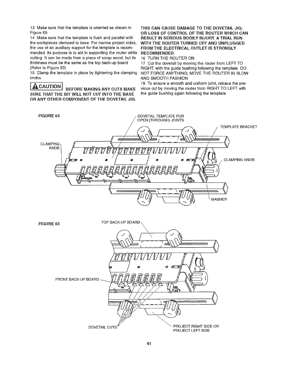
13Makesurethatthetemplateis oriented as shown in
Figure 65
14 Make sure that the template is flush and paraIlel with
the workpieces clamped to base For narrow project sides,
the use of an auxiliary support for the template is recom-
mended Its purpose is to aid in supporting the router while
cutting It can be made from a piece of scrap wood; but its
thickness must be the same as the top back-up board
(Refer to Figure 63)
!5 Clamp the template in place by tightening the clamping
knobs
I _,CAUTION ] BEFORE MAKING ANY CUTS MAKE
SURE THAT THE BIT WILL NOT CUT INTO THE BASE
OR ANY OTHER COMPONENT OF THE DOVETAIL JIG.,
THIS CAN CAUSE DAMAGE TO THE DOVETAIL JIG;
OR LOSS OF CONTROL OF THE ROUTER WHICH CAN
RESULT IN SERIOUS BODILY INJURY, A TRIAL RUN
WITH THE ROUTER TURNED OFF AND UNPLUGGED
FROM THE ELECTRICAL OUTLET IS STRONGLY
RECOMMENDED,,
16 TURN THE ROUTER ON
17 Cut the dovetail by moving the router from LEFT TO
RIGHT, with the guide bushing following the template DO
NOT FORCE ANYTHING; MOVE THE ROUTER IN SLOW
AND SMOOTH FASHION
18 To ensure a smooth and uniform joint, retrace the pre-
vious cut by moving the router from RIGHT TO LEFT with
the guide bushing again fofiowing the template
FIGURE 64
CLAMPING
KNOB
DOVETAIL TEMPLATE FOR
OPEN (THROUGH) ,,JOINTS
TEMPLATE BRACKET
CLAMPING KNOB
FIGURE 65 TOP BACK-UP BOARD\\
"x
0
FRONT BACK-UP BOARD
DOVETAIL CUTS" "_ PROJECT RIGHT SIDE OR
PROJECT LEFT SIDE
41
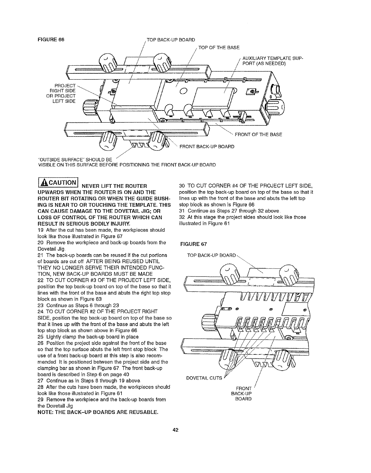
FIGURE 66 .TOP BACK-UP BOARD
TOPOFTHEBASE
/ / {J/'_'_. / / AUXILIARY TEMPLATE SUP-
N ....., / PonT,AsNEEOED
t ' -' J V /
R_GHTS_DE_ VI ,_ii // O / / i:P _/t U2,
"OUTSIDE SURFACE" SHOULD BE " i °
VISIBLE ON THIS SURFACE BEFORE PosmONING THE FRONT BACK-UP BOARD
[,_CAUTION J NEVER LIFT THE ROUTER
UPWARDS WHEN THE ROUTER IS ON AND THE
ROUTER BIT ROTATING OR WHEN THE GUIDE BUSH-
ING IS NEAR TO OR TOLICHING THE TEMPLATE. THIS
CAN CAUSE DAMAGE TO THE DOVETAIL JIG; OR
LOSS OF CONTROL OF THE ROUTER WHICH CAN
RESULT IN SERIOUS BODILY INJURY.
19 After the cut has been made, the workpieces should
look like those illustrated in Figure 67
20 Remove the workpieee and back-up boards from the
Dovetail Jig
2I The back-up boards can be reused if the cut portions
of boards are cut off AFTER BEING REUSED UNTIL
THEY NO LONGER SERVE THEIR INTENDED FUNC-
TION, NEW BACK-UP BOARDS MUST BE MADE
22 TO CUT CORNER #3 OF THE PROJECT LEFT SIDE,
position the top back-up board on lop of the base so that it
lines with the front of the base and abuts the fight top stop
block as shown in Figure 63
23 Continue as Steps 6 through 23
24. TO CUT CORNER #2 OF THE PROJECT RIGHT
SIDE, position the top back-up board on top of the base so
that it lines up with the front of the base and abuts the left
top stop block as shown above in Figure 66
25 Lightty clamp the back-up board in place
26 Position the project side against the front of the base
so that the top surface abuts the left front stop block The
use of a front back-up board at this step is also recom-
mended It is positioned between the project side and the
clamping bar as shown in Figure 67 The front back-up
board is described in Step 6 on page 40
27 Continue as in Steps 8 through 19 above
28 After the cuts have been made, the workpieces should
look like those illustrated in Figure 61
29 Remove the workpiece and the back-up boards from
the Dovetail Jig
NOTE: THE BACK-UP BOARDS ARE REUSABLE.
30 TO CUT CORNER #4 OF THE PROJECT LEFT SIDE,
position the top back_up board on top of the base so that it
lines up with the front of the base and abuts the ]eft top
stop block as shown is Figure 66
31 Continue as Steps 27 through 32 above
32 At this stage the project sides should look like those
illustrated in Figure 6!
FIGURE 67
TOP BACK-UPBOARD_
.........,_. .J
D
BACK_UP
BOARD
42
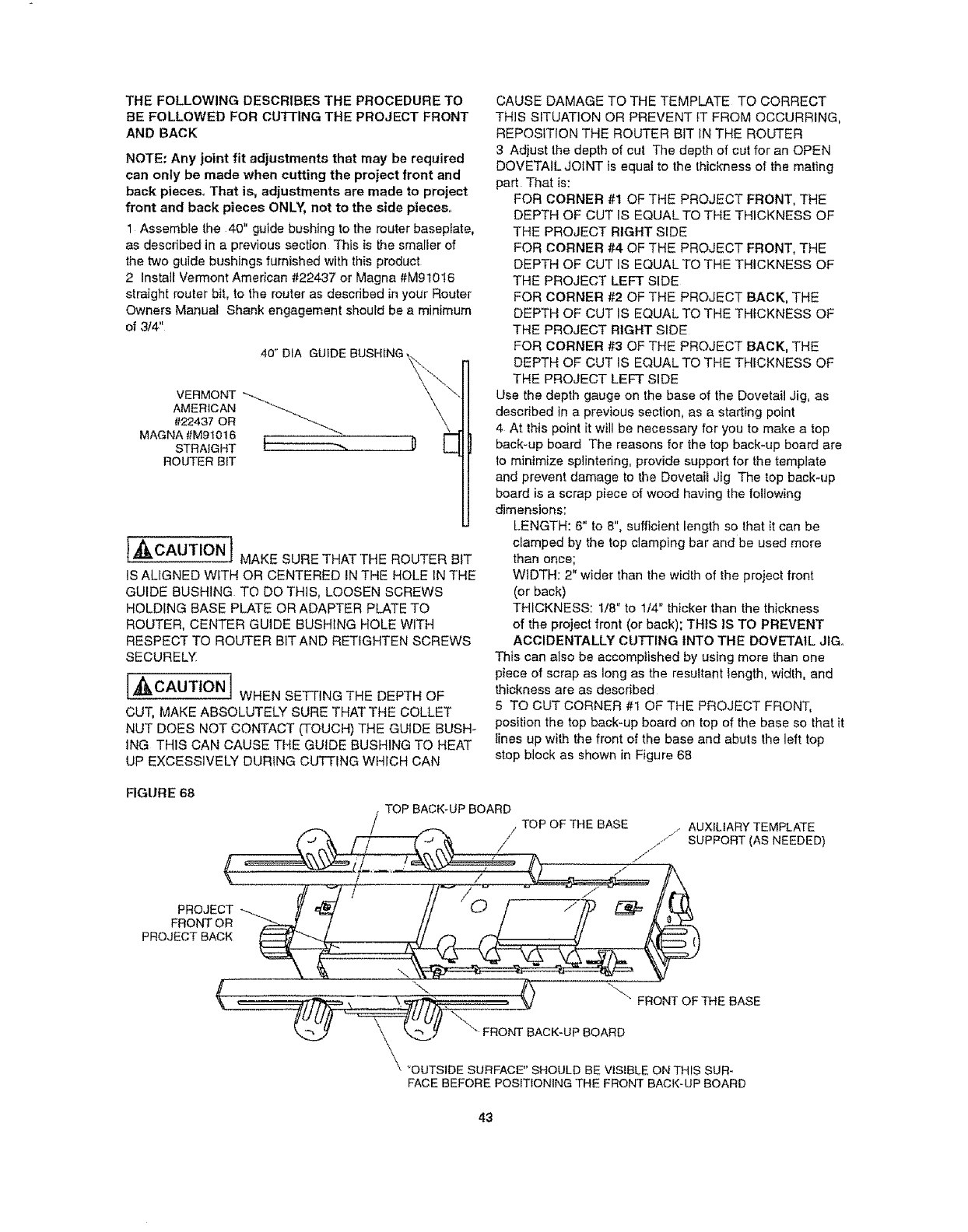
THE FOLLOWING DESCRIBES THE PROCEDURE TO
BE FOLLOWED FOR CU'i-FING THE PROJECT FRONT
AND BACK
NOTE: Any joint fit adjustments that may be required
can only be made when cutting the project front and
back pieces,, That is, adjustments are made to project
front and back pieces ONLY, not to the side pieces,
1 Assemble the 40" guide bushing to the router baseplate,
as described in a previous section This is the smaller of
the two guide bushings furnished with this product
2 Install Vermont American #22437 or Magna #M91016
straight router bit, to the router as described in your Router
Owners Manual Shank engagement should be a minimum
of 3/4"
AMERICAN
#22437 OR
MAGNA #M9!016 i0
STRAIGHT I "-_
ROUTER BIT
I,i'_ It =._CAUTION 1 MAKE SURE THAT THE ROUTER BIT
IS AUGNED WITH OR CENTERED tN THE HOLE IN THE
GUIDE BUSHING TO DO THIS, LOOSEN SCREWS
HOLDING BASE PLATE OR ADAPTER PLATE TO
ROUTER, CENTER GUIDE BUSHING HOLE WITH
RESPECT TO ROUTER BIT AND RETIGHTEN SCREWS
SECURELY
I'_CAUTION 1 WHEN SETTING THE DEPTH OF
CUT, MAKE ABSOLUTELY SURE THAT THE COLLET
NUT DOES NOT CONTACT (TOUCH) THE GUIDE BUSH-
ING THIS CAN CAUSE THE GUIDE BUSHING TO HEAT
UP EXCESSIVELY DURING CUTTING WHICH CAN
CAUSE DAMAGE TO THE TEMPLATE TO CORRECT
THIS S_TUATION OR PREVENT }T FROM OCCURRING,
REPOSITION THE ROUTER BIT IN THE ROUTER
3 Adjust the depth of cut The depth of cut for an OPEN
DOVETAIL JOINT is equal to the thickness of the mating
part That is:
FOR CORNER #t OF THE PROJECT FRONT, THE
DEPTH OF CUT IS EQUAL TO THE THICKNESS OF
THE PROJECT RIGHT StDE
FOR CORNER #4 OF THE PROJECT FRONT, THE
DEPTH OF CUT IS EQUAL TO THE THICKNESS OF
THE PROJECT LEFT SIDE
FOR CORNER #2 OF THE PROJECT BACK, THE
DEPTH OF CUT IS EQUAL TO THE THfCKNESS OF
THE PROJECT RIGHT SIDE
FOR CORNER #3 OF THE PROJECT BACK, THE
DEPTH OF CUT IS EQUAL TO THE THICKNESS OF
THE PROJECT LEFT SIDE
Use the depth gauge on the base of the Dovetail Jig, as
described in a previous section, as a starting point
4 At this point it will be necessary for you to make a top
back-up board The reasons for the top back-up board are
to minimize splintering, provide support for the template
and prevent damage to the DovetaiI Jig The top beck-up
board is a scrap piece of wood having the following
dimensions:
LENGTH: 6" to 8", sufficient length so that it can be
c_amped by the top clamping bar and be used more
than once;
WIDTH: 2" wider than the width of the project front
(or back)
THICKNESS: 1/8" to 1/4" thicker than the thickness
of the project front (or back); THIS IS TO PREVENT
ACCIDENTALLY CUTTING INTO THE DOVETAIL JIG,,
This can also be accomplished by using more than one
piece of scrap as long as the resultant length, width, and
thickness are as described
5 TO CUT CORNER #1 OF THE PROJECT FRONT,
position the top back-up board on top of the base so that it
lines up with the front of the base and abuts the left top
stop block as shown in Figure 68
FIGURE 68
TOP BACK-UP BOARD
/TOP OF THE BASE /AUXILIARY TEMPLATE
/j SUPPORT (AS NEEDED)
J
J
PROJECT
FRONT OR '"_-"-.-
PROJECT BACK
\
( _T/"]_ ', _-_//-;..: . _ '_ FRONT OF THE BASE
_OUTSIDE SURFACE' SHOULD BE VISIBLE ON THIS SUR*
FACE BEFORE POSITIONING THE FRONT BACK-UP BOARD
43
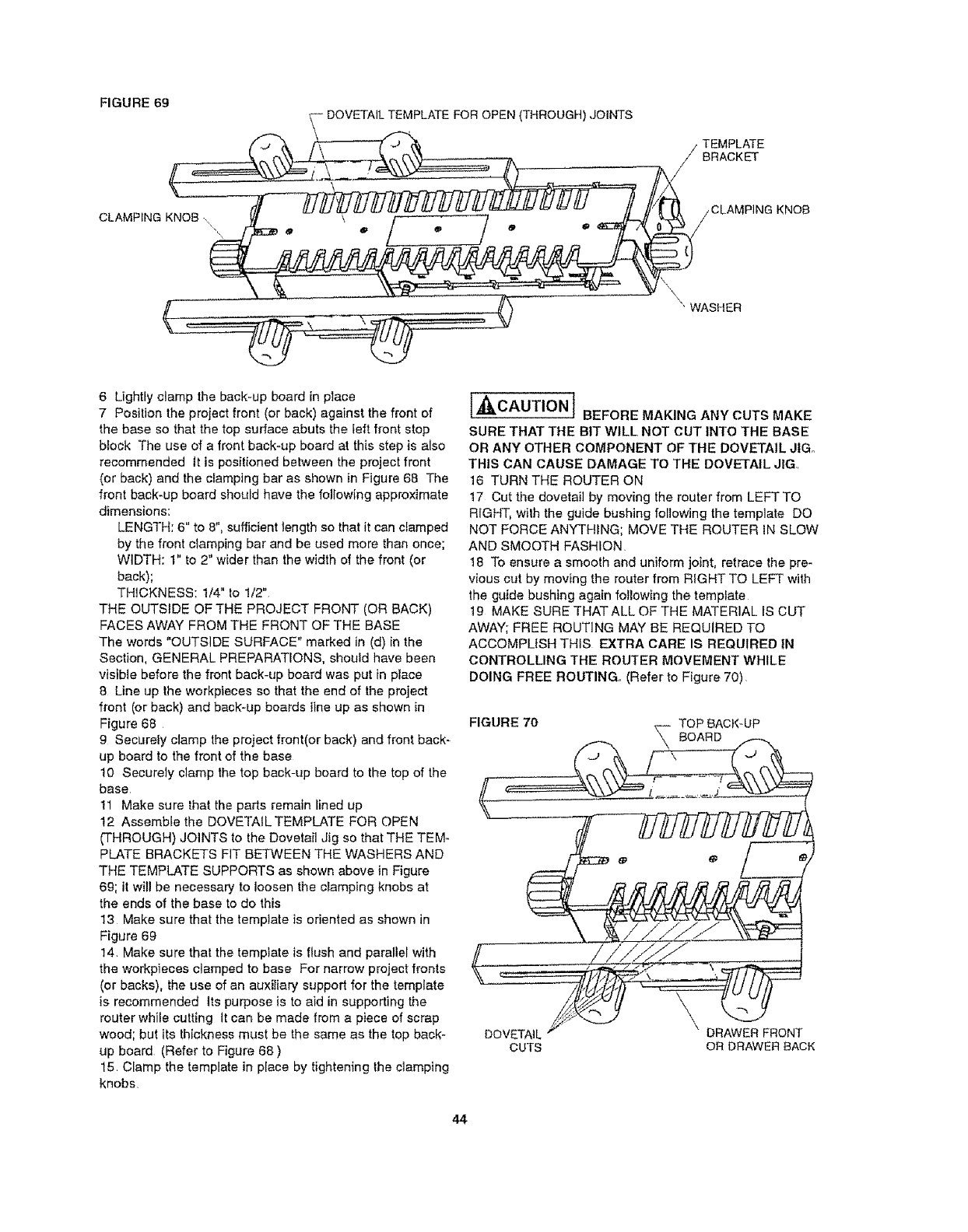
FIGURE 69
.9
6 Ughtiy clamp the back-up board in place
7 Posilion the project front (or back) against the front of
the base so that the top surface abuts the left front stop
biock The use of a front back_up board at this step is also
recommended it is positioned between the project front
(or back) and the clamping bar as shown in Figure 68 The
front back-up board should have the following approximate
dimensions:
LENGTH: 6" to 8", sufficient length so that it can clamped
by the front clamping bar and be used more than once;
WIDTH: 1" to 2" wider than the width of the front (or
back);
THICKNESS: 1/4" to 1/2"
THE OUTSIDE OF THE PROJECT FRONT (OR BACK)
FACES AWAY FROM THE FRONT OF THE BASE
The words "OUTSIDE SURFACE" marked in (d) in the
Section, GENERAL PREPARATIONS, should have been
visible before the front back-up board was put in place
8 Line up the workpieces so that the end of the project
front (or back) and back-up boards line up as shown in
Figure 68
9 Securely clamp the project front(or back) and front back-
up board to the front of the base
10 Securely clamp the top back-up board to the top of the
base
11 Make sure that the parts remain lined up
12 Assemble the DOVETAIL TEMPLATE FOR OPEN
(THROUGH) JOINTS to the Dovetail ,Jig so that THE TEM*
PLATE BRACKETS FIT BETWEEN THE WASHERS AND
THE TEMPLATE SUPPORTS as shown above in Figure
6g; it wil! be necessary to loosen the clamping knobs at
the ends of the base to do this
13 Make sure that the temptate is oriented as shown in
Figure 69
14. Make sure that the template is flush and parallel with
the workpieces clamped to base For narrow project fronts
(or backs), the use of an auxiliary support for the template
is recommended its purpose is to aid in supporting the
router while cutting it can be made from apiece of scrap
wood; but its thickness must be the same as the top back-
up board (Refer to Figure 68)
15 Clamp the template in place by tightening the clamping
knobs
iWI'_cAUTION I BEFORE MAKING ANY CUTS MAKE
SURE THAT THE BIT WILL NOT CUT INTO THE BASE
OR ANY OTHER COMPONENT OF THE DOVETAIL JIGo
THIS CAN CAUSE DAMAGE TO THE DOVETAIL JIG,
16 TURN THE ROUTER ON
17 Cut the dovetailby moving the routerfrom LEFT TO
RIGHT, with the guide bushing following the template DO
NOT FORCE ANYTHING; MOVE THE ROUTER IN SLOW
AND SMOOTH FASHION
18 To ensure a smooth and uniform joint, retrace the pre-
vious cut by moving the router from RIGHT TO LEFT with
the guide bushing again following the tempIate
!9 MAKE SURE THATALL OF THE MATERIAL IS CUT
AWAY; FREE ROUTING MAY BE REQUIRED TO
ACCOMPLISH THIS EXTRA CARE IS REQUIRED IN
CONTROLLING THE ROUTER MOVEMENT WHILE
DOING FREE ROUTING. (Refer to Figure 70)
FIGURE 70 TOP BACK-UP
_ BOARD
\
\
DOVETAIL DRAWER FRONT
CUTS OR DRAWER BACK
44
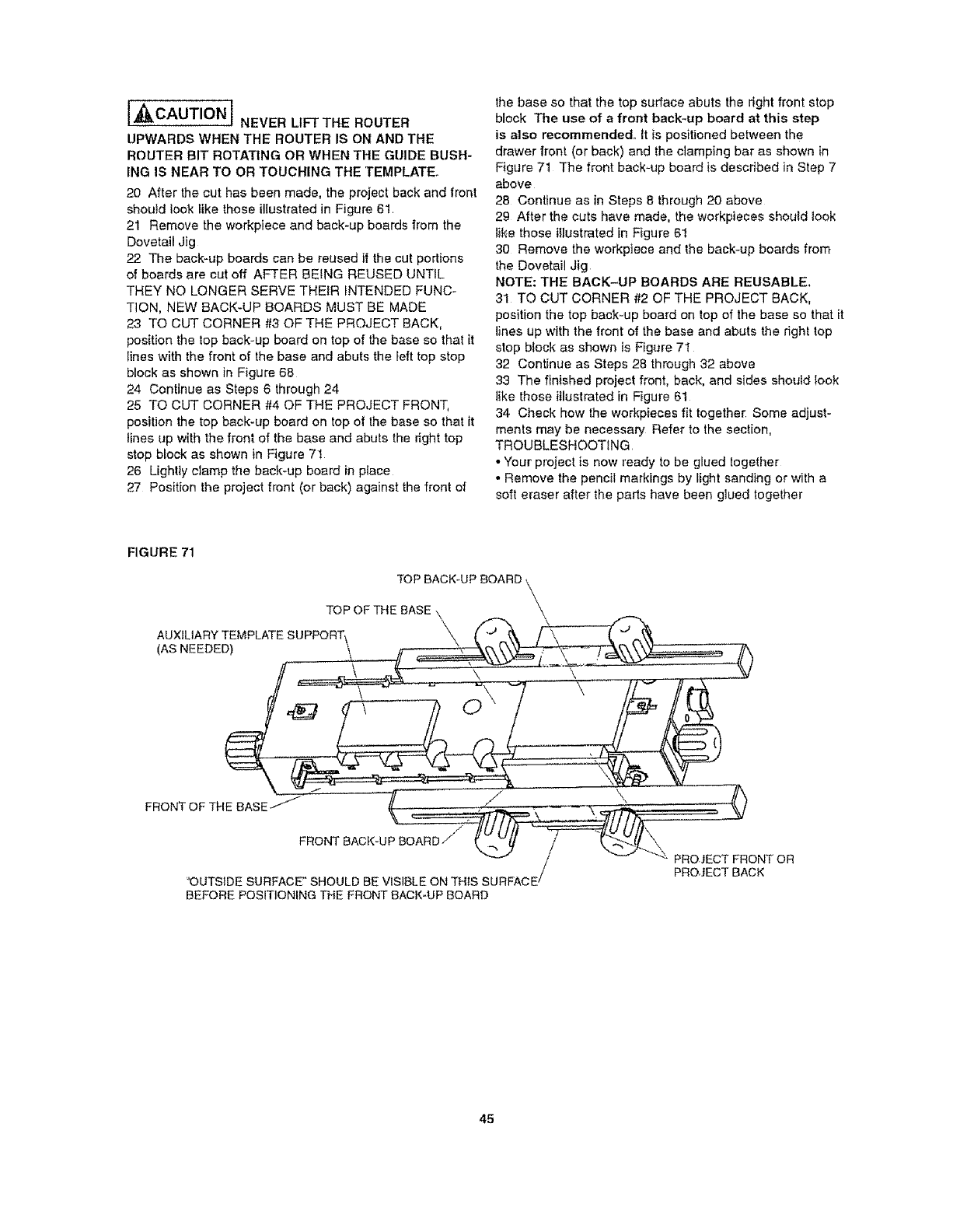
[_CAUTION j NEVER LIFT THE ROUTER
UPWARDS WHEN THE ROUTER IS ON AND THE
ROUTER BIT ROTATING OR WHEN THE GUIDE BUSH-
ING IS NEAR TO OR TOUCHING THE TEMPLATE.
20 After the cut has been made, the project back and front
should look like these illustrated in Figure 61
21 Remove the workpieee and back-up boards from the
Dovetail Jig
22 The back-up boards can be reused if the cut portions
of beards are cut off AFTER BEING REUSED UNTIL
THEY NO LONGER SERVE THEIR iNTENDED FUNC-
TION, NEW BACK-UP BOARDS MUST BE MADE
23 TO CUT CORNER #3 OF THE PROJECT BACK,
position the top back-up board on top of the base so that it
Iines with the front of the base and abuts the left top stop
block as shown in Figure 68
24 Continue as Steps 6 through 24
25 TO CUT CORNER #4 OF THE PROJECT FRONT,
posilion the top back-up beard on top of the base so that it
lines up with the front of the base and abuts the right top
stop block as shown in Figure 7t
26 Lightly clamp the back-up board in place
27 Position the project front (or back) against the front of
the base so that the top surface abuts the right front stop
block The use of a front back-up board at this step
is also recommended., tt is positioned between the
drawer front (or back) and the clamping bar as shown in
Figure 71 The front back-up board is described in Step 7
above
28 Continue as in Steps 8 through 20 above
29 After the cuts have made, the workpieces should look
like these illustrated in Figure 61
30 Remove the workpiece and the back-up boards from
the Dovetail Jig
NOTE: THE BACK-UP BOARDS ARE REUSABLE,,
31 TO CUT CORNER #2 OF THE PROJECT BACK,
position the top back-up board on top of the base so that [t
lines up with the front of the base and abuts the right top
stop block as shown is Figure 7t
32 Continue as Steps 28 through 32 above
33 The finished project front, back, and sides should took
like those illustrated in Figure 61
34 Check how the workpieces fit together Some adjust-
ments may be necessary Refer to the section,
TROUBLESHOOTING
• Your project is now ready to be glued together
• Remove the penciI markings by light sanding or with a
soft eraser after the parts have been glued together
FIGURE 71
TOP BACK-UP BOARD \
\
TOP OF THE BASE \
AUXIUARY TEMPLATE SUPPORT\ \ '_ "_ \f"_\
(AS NEEDED) tt_
__.XV
- 2%
_- ,,,:,.%. ,, ,.....
FRONT OF THE BASE / /_ / ........ '_
----t /_ ""_ PROJECT FRONT OR
tPROJECT BACK
'OUTSIDE SURFACE" SHOULD BE VISIBLE ON THIS SURFACE /
BEFORE POSITIONING THE FRONT BACK-UP BOARD
45
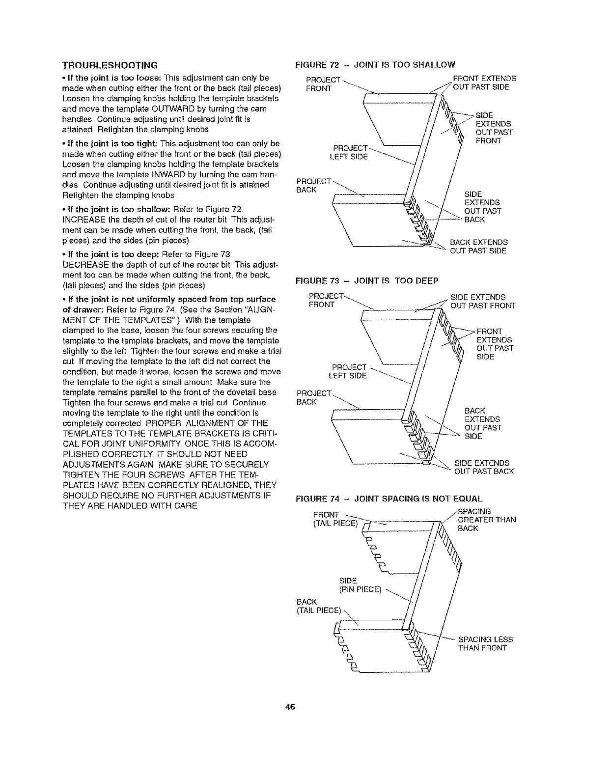
TROUBLESHOOTING
•If the joint is too loose: This adjustment can only be
made when cutting either the front or the back (tail pieces)
Loosen the clamping knobs holding the template brackets
and move the template OUTWARD by turning the cam
handles Continue adjusting until desired joint fit is
attained Retighten the clamping knobs
• If the joint is too tight: This adjustment too can oniy be
made when cutting either the front or the back (tail pieces)
Loosen the clamping knobs holding the template brackets
and move the template INWARD by turning the cam han-
dles Continue adjusting until desired ioint fit is attained
Retighten the clamping knobs
• If the joint is too shallow: Refer to Figure 72
INCREASE the depth of cut of the router bit This adjust-
ment can be made when cutling the front, the back, (tail
pieces) and the sides (pin pieces)
• If the joint is too deep: Refer to Figure 73
DECREASE the depth of cut of lhe router bit This adjust-
ment too can be made when cutting the front, the back,
(tail pieces) and the sides (pin pieces)
• If the joint is not uniformly spaced from top surface
of drawer: Refer to Figure 74 (See the Section "ALIGN-
MENT OF THE TEMPLATES" ) With the template
clamped Io the base, loosen the four screws securing the
template to the template brackets, and move the template
slightly to the left Tighten the four screws and make a tdal
cut If moving the template to the left did not correct the
condition, but made it worse, loosen the screws and move
the template to the right a small amount Make sure the
template remains parallel to the front of the dovetail base
Tighten the four screws and make a thai cut Continue
moving the template to the right until the condition is
completely corrected PROPER ALIGNMENT OF THE
TEMPLATES TO THE TEMPLATE BRACKETS IS CRITI-
CAL FOR JOINT UNIFORMITY ONCE THIS IS ACCOM-
PUSHED CORRECTLY, IT SHOULD NOT NEED
ADJUSTMENTS AGAIN MAKE SURE TO SECURELY
TIGHTEN THE FOUR SCREWS AFTER THE TEM-
PLATES HAVE BEEN CORRECTLY REALIGNED, THEY
SHOULD REQUIRE NO FURTHER ADJUSTMENTS IF
THEY ARE HANDLED WITH CARE
FIGURE 72 - JOINT tS TOO SHALLOW
PRoJ FRONT EXTENDS
FRONT PAST SIDE
LEFT SIDE
>SIDE
EXTENDS
OUT PAST
FRONT
PROJECTo_._
BACK "_ SIDE
EXTENDS
OUT PAST
BACK
BACK EXTENDS
OUT PAST SIDE
FIGURE 73 - JOINT IS TOO DEEP
SIDE EXTENDS
FRONT OUT PAST FRONT
PROJECT
LEFT SIDE_.....
_ FRONT
EXTENDS
% PAST
BACK
EXTENDS
OUT PAST
SIDE
SIDE EXTENDS
OUT PAST BACK
FIGURE 74 - JOINT SPACING IS NOT EQUAL
FRONT ---__ j/SPACING
{TAIL PIECE) _ ,_ GREATERAcKTHAN
SIDE /
(PIN PIECE) _ //
BACK, 7/
(TAIL PIECE) .,.\ / /
SPACiNaLESS
THAN FRONT
46

PARTSLIST FOR VERMONT AMERICAN INDUSTRIAL DOVETAIL JIG MODEL NO,,23461
KEY PART No, DEscRIPTION
1 29LD-87g-I Detuxe Dovetail Base
2 29LD_880q Dove| aiLTem_lat e LB.rmdJ_n!) ............
329LD-881-1 Dove|a! !Templat e (Open .!o)n!)
4 29LD-882 Temp__Je SuEEport (Right Side)
5 2gLD-B83 Tern_ Support (Le|t Side)
6 29LD°884q Cam Handle
7 29LD-885-1 Front Stop Block
8 29LD-886-1 .To_£p Block
9 29LD-887 Ciamj_.g Bar End Cap_
10 29LD-888-1 Retainer
11 29LD-889-1 Bol_ Support
12 29LD_890-1 Clamping Knob
!3 29LD_891 C!#rnping Bar
!QT¥ KEY PART NO. DESCR|PTtON QTY
i- 1 24 29L-489-13 #!O*32XS/8"lg Panhoad Machine Screw ._4_
1 25 29L-469-14 #10-32 X 3/8" Ig. Panhead Machine Screw 8
26 29Lo469q5 #8=36 X 3/16" Ig. Panhead Machine Scre w 10
27 29LD-841-2 !1-10_32X 5/8" Ig Flat Head Mac_ Scr%w 2
28 2gLD-841-3 #!O"32 X 7/8" !g_ Fiat Head Machine Screw 2
i 2 29 _ 29L._D_:.841..:4- _;10-32 X 3/8" Ig. Flat Head Machine Screw 3
i 2 30 29L-684o6 #10.16X1/2" i&.Panhead .Taj)p}ng, Sct'ew !
i 2 . 31 29L-684-7 , #'i_16X!"!g PanheadTa£pingscrew 3
4 32 29A-310-15 5/!_!8 X'4:!/2" ]g_ RD HD SQ Neck Bolt 2
1 33 29A-310,16 5/16-18 X 3-1/2" !g:. RD HD SQ Neck Bolt 2
4 34 29A-310-17 5!16-18 X 2" _q. RD HD SQ Neck Bolt _.2.
635 29A-242-t2 #t0-32 Hex Machine Screw Nul 4
2 36 29A-242-13 5/16-18 t-.lex Machine Screw Nut 2
14 . 29LD-892 . PivoIShalt . 1
15
16
17
t8
19
2O
21
22
23
29LD-895
29LD_896
29LD-899
2gLD-900
29LD-98t
Template Bracket
Template Sti|_ener
Guide Bushing Assembly (.4" Din,)
Guide Bushin_ Assembl_" Din,) __
__n Sprin 9______.__ ,...__ _
37 2gA_306-20 t3/64" [D X 15132" OD X 3/64"
= 4 Thick Washer 13
2 38 29A-306-40 11/32" ID X 7/8" OD X 1/t6" Thick Washer 8
139 29LD-930 II/32' ID X 7/8" OD Thin Nylon Washer 4
1 40 29LD-969 5/16" ID X 7t8" OD Thick Nylon Washer 4
4 41 29LCN-1Q08 S_r}ng Retainer 4
Product Label (Clamping Bar }1 42 29A_368"! #8 Countersunk Bushing 4__
Label {Temj?late-Blind) 1 43 29A-368-2 #t 0 Countersunk Bushing 4
44 2gGD-375 Router Adapter PIale 1
45 VA #25500 1/2" VA Dovetail Router Bit 1
:_ 45LCN-72 ins,'ruction Manual I 1
45A-414
45A-416
45A-417 _plate43_) ..... 1 __
45A-415 Warning Label(C!amp!ng Bar) 1
Key No's 29.42.43. 44. and 45 a!ong with four o! Key No 37 are furnished loose and unassembied
47
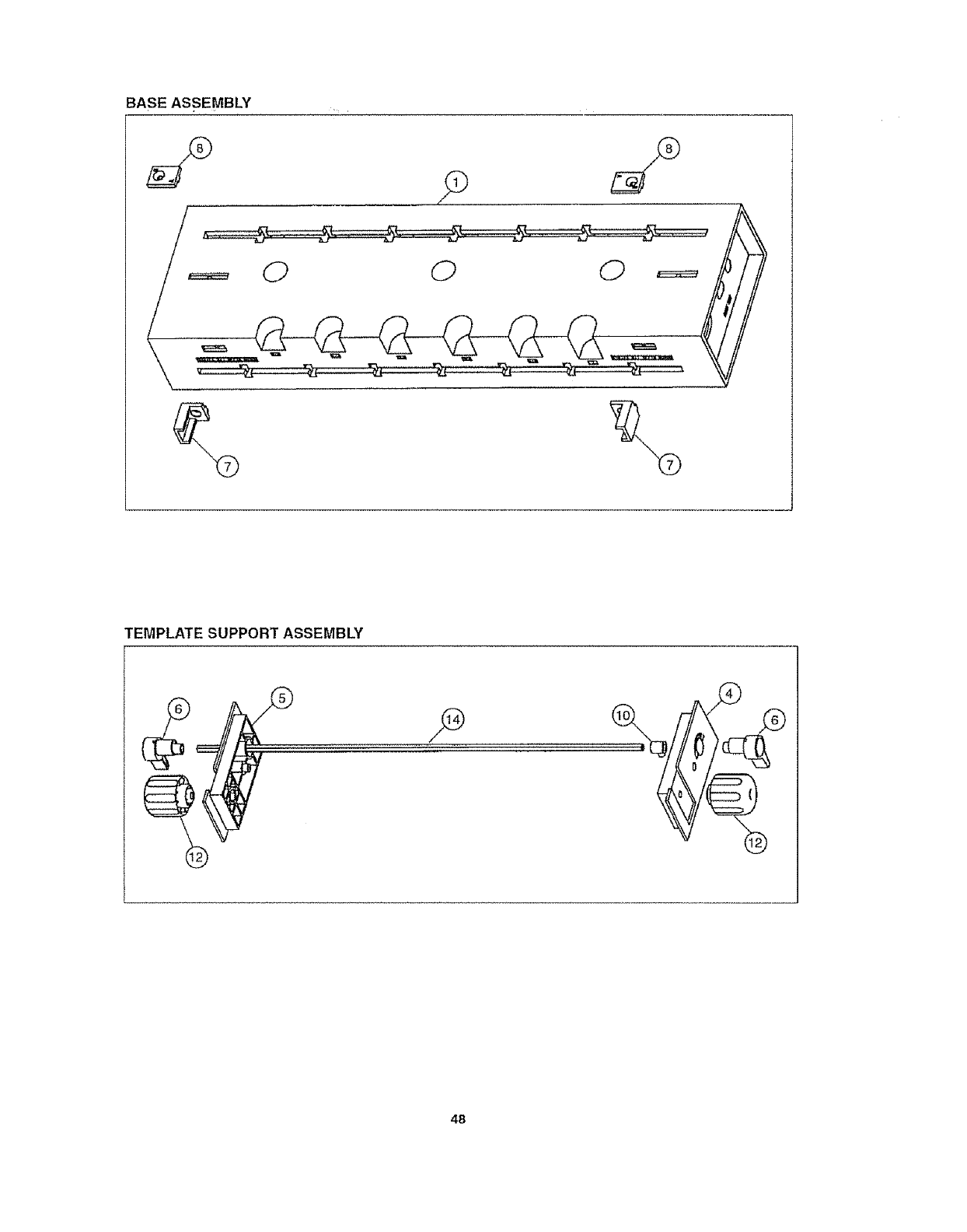
BASE ASSEMBLY
o
TEMPLATE SUPPORT ASSEMBLY
48
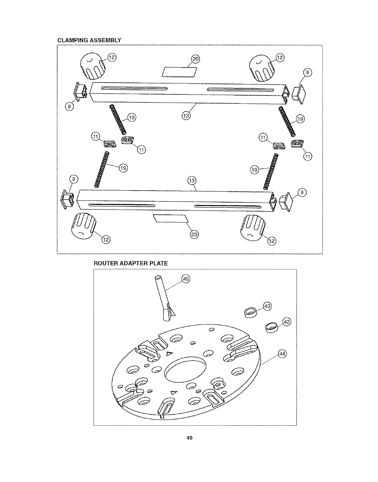
CLAMPING ASSEMBLY
i/
ROUTER ADAPTER PLATE
49
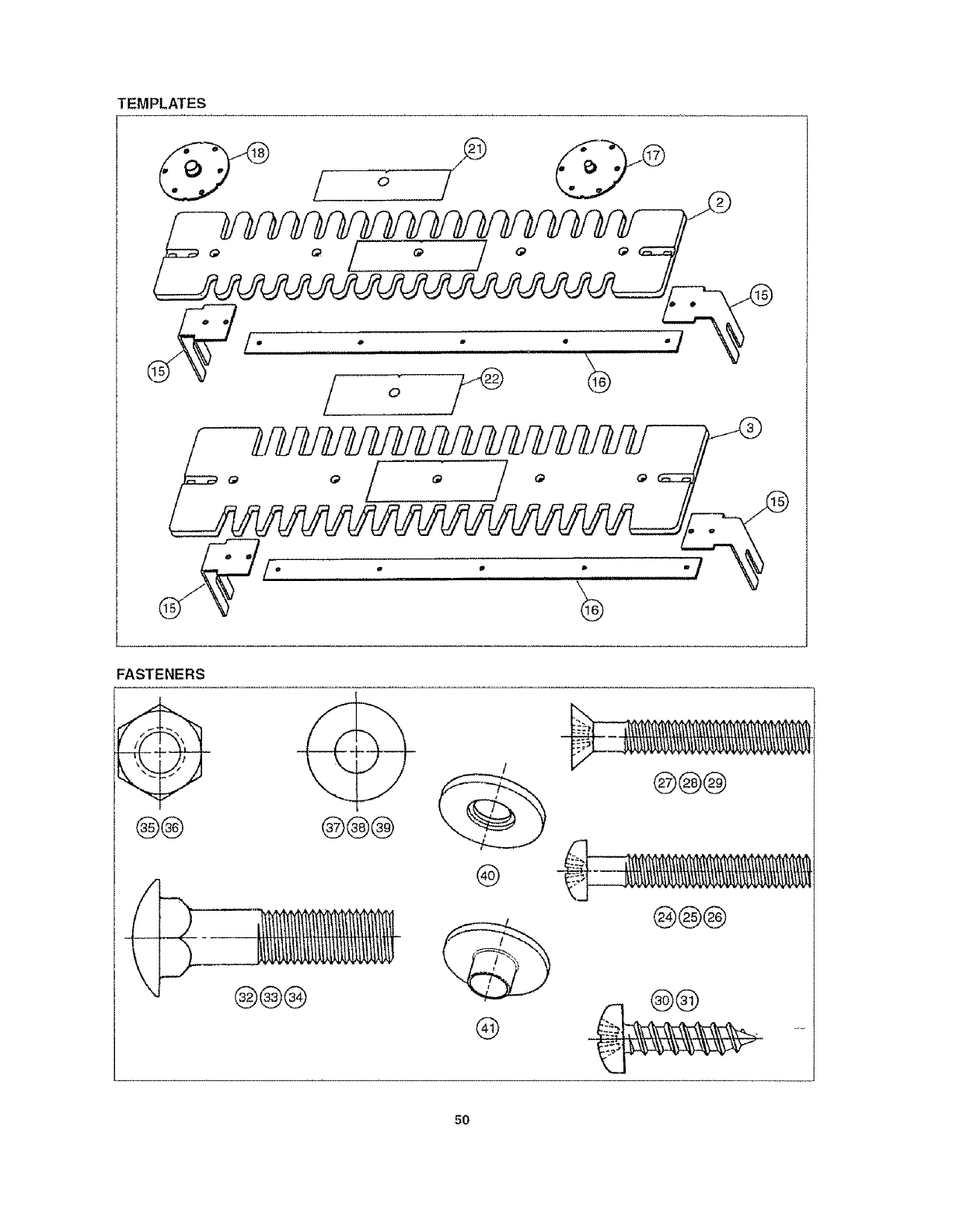
TEMPLATES
........ o,,
o
/
,/
/
FASTENERS
@®
/
®@@
@@@
@
@@@
\@@@ Q
50

51

To obtain a copy of this Manual in French, call
the following toll4ree number 1-800-742_3869
To obtain a copy of this Manual in Spanish, calt
the following toll-free number 1-800-742-3869
When corresponding, always give the following
information as shown in the list
Printed in U_SoAo
08/99
Manual No. 45LCN-72
1 The PART NUMBER
2 The PART DESCRIPTION
3 The MODEL NUMBER: 23461
4 The ITEM NAME - INDUSTRIAL DOVETAIL JIG
i i i i
