CRAFTSMAN Walk Behind Lawnmower, Gas Manual L0812060
User Manual: CRAFTSMAN CRAFTSMAN Walk Behind Lawnmower, Gas Manual CRAFTSMAN Walk Behind Lawnmower, Gas Owner's Manual, CRAFTSMAN Walk Behind Lawnmower, Gas installation guides
Open the PDF directly: View PDF ![]() .
.
Page Count: 26
SEARS
®
MODEL NUMBER 917.379310 OWNER'S MANUAL
•Assembly
Operation
• Customer
Responsibilities
=Service
Adjustments
Repair Parts
Caution:
Read and Follow
all Safety Rules
and Instructions
Before Operating
This Equipment
159060 1.2.97 VBL Printed in U.S,A.
SAFETY RULES
Safe Operation Practices for Walk-Behind Mowers
IMPORTANT: THIS CUTTING MACHINE IS CAPABLE OF AMPUTATING HANDS AND FEET AND THROWING OBJECTS.
FAILURE TO OBSERVE THE FOLLOWING SAFETY INSTRUCTIONS COULD RESULT iN SERIOUS iNJURY OR DEATH.
SAFETY STANDARDS REQUIRE OPERATOR PRESENCE CONTROLS TO MINIMIZE THE RISK OF INJURY. YOUR UNIT IS
EQUIPPED WITH SUCH CONTROLS. DO NOT ATTEMPT TO DEFEAT THE FUNCTION OF THE OPERATOR PRESENCE
CONTROLS UNDER ANY CIRCUMSTANCES,
TRAINING:
•Read this operator's manual carefuUy. Become familiar with
the controls and know how to operate your mower property.
Learn how to quickly stop mower.
•Do not allow children to use your mower. Never allow adults
to use mower without proper instructions.
•Keep the area of operation clear of all persons, especially
small chitdren and pets.
=Use mower only as the manufacturer intended and as de-
scribed in this manual.
,, Do not operate mower if it has been dropped or damaged in
any manner. Always have damage repaired before using
your mower.
* Do not use accessory attachments that are not recommended
by the manufacturer. Use of such attachments may be
hazardous.
°The blade turns when the engine is running.
PREPARATION:
° Always thoroughlycheckthearea tobe mowedandclearitof
all stones, sticks,wires, bones, and otherforeign objects.
These objectswiltbe thrownby the blade and can cause
severe injury.
°Always wear safetyglassesoreye shieldswhenstartingand
whileusingyourmower.
° Dress properly. Do not operate mowerwhen barefootor
wearing open sandals. Wear only solid shoeswith good
tractionwhenmowing.
•Checkfuel tank before startingengine. Do notfill gas tank
indoors,whentheengineisrunningorwhentheengineishot.
Allowthe engineto coolfor severalminutesbefore filling the
gas tank. CIean off any spilledgasolinebeforestartingthe
engine.
• Alwaysmakewheel heightadjustmentsbeforestartingyour
mower. Neverattemptto dothiswhilethe engineis running.
Mow only in daylightor goodartificiallight.
OPERATION:
• Keep your eyes and mind on your mower and the area being
cut. Do not let other interests distract you.
• Do not mow wet or slippery grass. Never run while operating
your mower. Always be sure of your footing -keep a firm hold
on the handles and walk.
• Do not put hands or feet near or under rotating parts. Keep
clear of the discharge opening at all times.
• Always stop the engine whenever you leave or are not using
your mower, or before crossing driveways, walks, roads, and
any gravel-covered areas.
,, Never direct discharge of material toward bystanders nor
allow anyone near the mower while you are operating it.
°Before cleaning, inspecting, or repairing your mower, stop the
engine and make absolutely sure the blade and all moving
parts have stopped. Then disconnect the spark plug wire and
keep it away from the spark plug to prevent accidental
starting.
o
°
° Do not continue to run your mower ifyou hit a foreign object.
Follow the procedure outlined above, then repair any dam-
age before restarting and operating you mower.
o Do not change the governor settings or overspeed the
engine. Engine damage or personal injury may result.
•Do not operate your mower if it vibrates abnormally. Exces-
sive vibration is an indication of damage; stop the engine,
safely check for the cause of vibration and repair as required.
Do not run the engine indoors. Exhaust fumes are danger-
ous.
Never cut grass by pulling the mower towards you. Mow
across the face of slopes, never up and down or you might
toseyourfooting. Donot mowexcessivelysteepslopes. Use
caution when operating the mower on uneven terrain orwhen
changing directions - maintain good footing.
° Never operate your mower without proper guards, plates,
grass catcher or other safety devices in place.
MAINTENANCE AND STORAGE:
- Check the blade and the engine mounting bolts often to be
sure they are tightened properly.
°Check all bolts, nuts and screws at frequent intervals for
proper tightness to be sure mower is in safe working condi-
tion.
• Keep all safety devices in place and working.
°To reduce fire hazard, keep the engine free of grass, leaves
or excessive grease and oil.
• Check grass catcher often for deterioration and wear and
replace worn bags. Use only replacement bags that are
recommended by and comply with specifications of the
manufacturer of your mower.
,, Always keep a sharp blade on your mower.
° Allow engine to cool before storing in any enclosure.
°Never store mower with fuel in the tank inside a building
where fumes may reach an open flame or an ignition source
such as a hot water heater, space heater, clothes dryer, etc.
Look for this symbol to point out ira-
portant safety precautions. It means
CAUTION!!! BECOMEALERT!!! YOUR
SAFETY iS INVOLVED.
CAUTION: Always disconnect spark
plug wire and place wire where it can-
not contact spark plug in order to pre-
vent accidental starting when setting
up, transporting, adjusting or making
repairs.
; WARNING -"
The engine exhaust from this product con-
tains chemicals known to the State of Califor-
nia to cause cancer, birth defects, or other
reproductive harm.
2
CONGRATULATIONS on your purchase of a Sears Lawn
Mower. it has been designed, engineered and manufac-
tured to give you the best possible dependability and
performance.
Should you experience any problem you cannot easily
remedy, please contact your nearest Sears Authorized
Service Center/Department. We have competent, weIF
trained technicians and the proper tools to service or repair
this lawn mower.
Please read and retain this manual. The instructions will
enable you to assembte and maintain your lawn mower
properly. Always observe the "SAFETY RULES".
MODEL
NUMBER 9!7,379310
SERIAL
NUMBER
DATE OF PU RCHASE
THE MODEL AND SERIAL NUMBERS WILL BE FOUND
ON A DECAL ATTACHED TO THE REAR OF THE
LAWN MOWER HOUSING
YOU SHOULD RECORD BOTH SERIAL NUMBER AND
DATE OF PURCHASE AND KEEP tN A SAFE PLACE
FOR FUTURE REFERENCE.
PRODUCT SPECiFiCATIONS
HORSEPOWER: 6.6
DISPLACEMENT: 12,56 cu. in.
GASOLINE CAPACITY
AND TYPE: ! .5 quart
UNLEADED R EGULAR
OIL TYPE (APf-SFiSG): SAE 30 (above 32_F)
SAE 5W_30 (below 32°F)
OIL CAPACITY: 27 oz.
SPARK PLUG: CHAMPION J19LM, RJ19LM
(GAP: .030") STD361458
VALVE CLEARANCE: INTAKE: .008"
EXHAUST: .008"
SOLID STATE IGNITION
AIR GAP: .0125 in.
BLADE BOLT TORQUE: 35-40 FT. LBS.
MAINTENANCE AGREEMENT
A Sears Maintenance Agreement is available on this product. Contact your nearest Sears store for details.
CUSTOMER RESPONSmBILITIES
-Read and observe the safety rules,
-Follow a regular schedule in maintaining, caring for and using your lawn mower.
Follow the instructions under "Customer Responsibilities" and "Storage" sections of this owner's manual,
LIMITED TWO YEAR WARRANTY ON CRAFTSMAN POWER MOWER
For two years from date of purchase, when this Craftsman Lawn Mower is maintained, lubricated, and tuned up
according to the operating and maintenance instructions in the owner's manual, Sears will repair free of charge any
defect in material or workmanship,
If this Craftsman Lawn Mower is used for commercial or rental purposes, this warranty applies for only 90 days from
the date of purchase.
This Warranty does not cover:
•Expendable items which become worn during normal use, such as rotary mower blades, blade adapters, belts,
air cteaners and spark plug.
Repairs necessary because of operator abuse or negligence, including bent crankshafts and the failure to maintain
the equipment according to the instructions contained in the owner's manual.
WARRANTY SERVICE tS AVAILABLE BY RETURNING THE CRAFTSMAN POWER MOWER TO THE NEAREST
SEARS SERVICE CENTER/DEPARTMENT IN THE,UNITED STATES, THIS WARRANTY APPLIES ONLY WHILE
THIS PRODUCT IS IN USE tN THE UNITED STATES.
This Warranty gives you specific legal rights, and youmay also have other rights which vary from state to state.
SEARS, ROEBUCK AND CO., D/817 WA, HOFFMAN ESTATES, ILLINOIS 60179
3
TA LE OF CONTENTS
._ . _... _............................. -....... ... _ _ __. . = ._
SAFETY RULES ............................................................ 2
PRODUCT SPECIFICATIONS ...................................... 3
CUSTOMER RESPONSIBILITIES ..................... 3, 12-14
WARRANTY .................................................................. 3
ASSEMBLY ......................................................... :......... 6
OPERATION. ................................................................. 7
MAINTENANCE SCHEDULE ...................................... 11
SERVICE AND ADJUSTMENTS ................................. 14
STORAGE ................................................................ ;.. 15
TROUBLESHOOTING ................................................. 16
REPAIR PARTS -LAWN MOWER ........................ 18-22
REPAIR PARTS -ENGINE .................................... 23-25
PARTS ORDERING/SERVICE .................................... 26
iNDEX
A
Accessories ........................................... 5
Adjustments:
Carburetor. .................................. 15
Engine Speed ............................. 15
Handle Height ............................. 15
Height of Cut ................................. 8
Air Filter:
Replacement ............................... 13
Service ........................................ 13
Assembly ............................................. .6
B
Blade:
Sharpening ................................. 12
Replacement ............................... I2
C
Controls:
Drive Control ................................. 8
Engi ne Zone Control ..................... 8
Engine Speed Control ................... 8
Operator Presence Control Bar .... 8
Customer Responsibilities...._ .... 3, 11-13
Air Filter ....................................... 13
Blade Care/Replacement ............ 12
Drive Wheels ............................... !2
Engine ......................................... 13
Lubrication ................................... 13
Spark Plug .................................. 13
Cutting Levels ...................................... 8
E
Engine:
Air Filter ....................................... 13
Oil Change .................................. 13
Oii Leve! ...................................... 13
Oil Type ....................................... 13
Starting .......................................... 9
Stopping ........................................ 9
Storage ....................................... 15
F
Fuel:
Capacity ........................................ 3
Storage ....................................... t5
Type .............................................. 9
L
Lubrication:
Engine ......................................... 13
Lawn Mower ................................ t I
M
Maintenance Agreement ...................... 3
Maintenance Schedule ...................... 11
Mowing Tips ....................................... 10
Oil:
O
Engine ........................................... 9
Ste rage ....................................... 15
Operation:
Drive Control ............ _................... .8
Engine Control ............................... 8
Grass Catcher ................ ................ 9
Mower ........................................... 8
Operator Presence Control Bar .... 8
Options:
Accessories ........... o....................... 5
R
Repair Parts:
Engine .................................... 23-25
Lawn Mower ........................... 18-22
Responsibilities, Customer ........ 3, 11-13
S
Safety Rules ......................................... 2
Service and Adjustments ................... 14
Carburetor ................................... 15
Engine Speed .................. ;,......... t5
Handle ......................................... 15
Spark Plug; ......................................... 13
Specifications ....................................... 3
Speed Control:
Engine ........................................... 9
Starting the Engine .............................. 9
Stopping the Engine ............................. 9
Storage ........................................ ....... t 5
T
Troubleshooting Chart ........................ 16
W
Warranty ............................................. :. 3
4
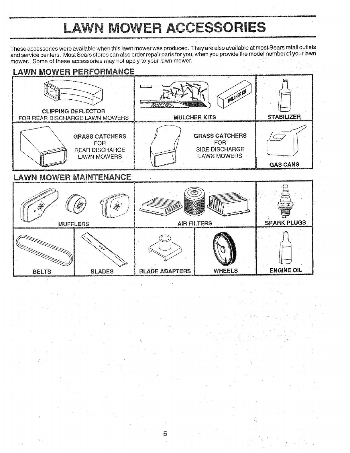
LAWN MOWER ACCESSO IE
These accessories were available when this lawn mower was produced. They are also available at moSt Sears retail outlets
and se rvice centers. Most Sears stores can also order repair parts for you, when you provide the model number of your lawn
mower, Some of these accessories may not apply to your lawn mower.
.AWN MOWER PERFORMANCE
CLIPPING DEFLECTOR
FOR REAR DISCHARGE LAWN MOWERS
\\\X
GRASS CATCHERS
FOR
REAR DISCHARGE
LAWN MOWERS
LAWN MOWER MAmNTENANCE
MULCHER KiTS
GRASS CATCHERS
FOR
SiDE DISCHARGE
LAWN MOWERS
_._ = = .... ._. _- _=
MUFFLERS
BELTS BLADES
AIR FILTERS
BLADE ADAPTERS WHEELS
STABILIZER
GAS CANS
_- __ _ _ _ _._ _=
SPARK PLUGS
ENGINE OIL
5
ASSE BLY
Read these instructions and this manual in its entirety
before you attempt to assemble or operate your new lawn
mower. Your new lawn mower has been assembled at the
factory with the exception of those parts left unassembfed
for sh_pping purposes, To ensure safe and proper opera-
tion of your lawn mower, all parts and hardware you
assemble must be tightened securely. Use the correct
tools as necessary to ensure proper tightness. All parts
such as nuts, washers, bolts, etc., necessary to complete
the assembly have been placed in the parts bag.
TO REMOVE LAWN MOWER FROM
CARTON
•Remove loose parts included with mower.
- Cut down two end corners of carton and lay end panel
down flat.
- Remove all packing materials except padding between
upper and lower handle and padding holding operator
presence control bar to upper handle,
• Roll lawn mower out of carton and check carton thor-
oughly for additional loose parts.
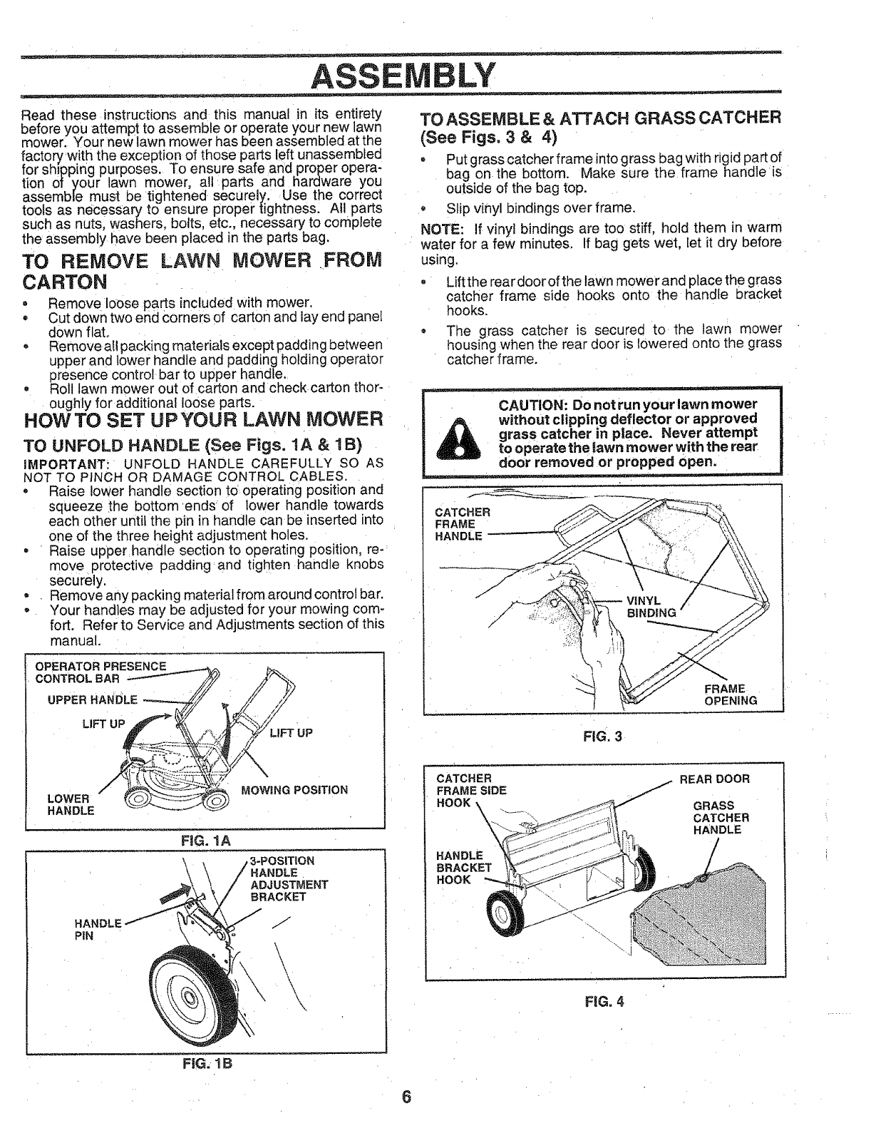
HOWTO SET UPYOUR LAWN MOWER
TO UNFOLD HANDLE (See Figs. 1A & 1B)
iMPORTANT: UNFOLD HANDLE CAREFULLY SO AS
NOT TO PINCH OR DAMAGE CONTROL CABLES.
• Raise lower handle section to operating position and
squeeze ;the bottom ends of lower handle towards
each other until the pin in handle can be inserted into
one of the three height adjustment holes.
• Raise upper handle section to operating position, re-
move protective padding and tighten handle knobs
securely,
= Remove any packing material from around control bar.
-Your handles may be adjusted for your mowing com-
fort. Refer to Service and Adjustments section of this
manual.
OPERATOR
CONTROLBAR
UPPER HANDLE
LIFTUP_
LOWER
HANDLE
LIFT UP
MOWING POSITION
FIG. 1A
HANDLE
ADJUSTMENT
BRACKET
HANDLE
PiN
\\
/.-
./
TO ASSEMBLE &ATTACH GRASS CATCHER
(See Figs. 3& 4)
Put grass catcher frame into grass bag with rigid part of
bag on the bottom. Make sure the frame handle is
outside of the bag top.
• Slip vinyl bindings over frame.
NOTE: If vinyl bindings are too stiff, hold them in warm
water for a few minutes. If bag gets wet, let it dry before
using.
Lift the reardoorof the lawn mower and place the grass
catcher frame side hooks onto the handle bracket
hooks.
® The grass catcher is secured to the lawn mower
housing when the rear door is lowered onto the grass
catcher frame.
CATCHER
FRAME
HANDLE
FIG. 3
FRAME
OPENING
CATCHER
FRAME SIDE
HOOK \
HANDLE
BRACKET
HOOK
REAR DOOR
GRASS
CATCHER
HANDLE
FeGo4
FiG. 1IB
OPERATION
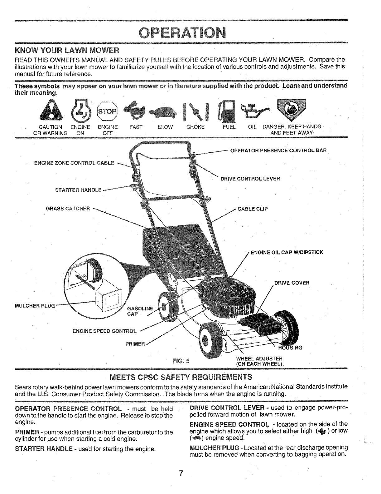
KNOW YOUR LAWN MOWER
READ THIS OWNER'S MANUAL AND SAFETY RULES BEFORE OPERATING YOUR LAWN MOWER, Compare the
illustrations with your lawn mower to familiarize yoursetf with the location of various controls and adjustments. Save this
manual for future reference.
These symbols may appear on your fawn rnewer er in _iter_ture supplied with the product. Learn and understand
their meaning_
CAUTION ENGINE ENGINE FAST SLOW CHOKE FUEL OiL DANGER, KEEP HANDS
OR WARNING ON OFF AND FEET AWAY
OPERATOR PRESENCE CONTROL BAR
ENG{NE ZONE CONTROLCABLE
STARTER HANDLE
DRmVECONTROL LEVER
GRASS CATCHER CLIP
' ENGINE OIL CAP W/DIPSTICK
MULCHER GASOHNE
CAP
WHEEL ADJUSTER
F_G° 5; (ON EACH WHEEL)
MEETS CPSC SAFETY REQUIREMENTS
Sears rotary walk-behind power lawn mowers conform to the safety standards of the American National Standards Institute
and the U.S° Consumer Product Safety Commission. The blade turns when the engine is running,
OPERATOR PRESENCE CONTROL o:must be held
down tothe handle to start the engine. Release to stop the
engine.
PRIMER - pumps additional fuel from the carburetor to the
cylinder for use when starting a cold engine.
STARTER HANDLE; o used for starting the engine°
DRIVE CONTROL LEVER - used to engage power-pro-
pelled forward motion of lawn mower.
ENGINE SPEED CONTROL - located on the side of the
engine which allows you to select either high (4) or low
(,,_) engine speed.
MULCHER PLUG =Located at the rear discharge opening
must be removed when converting to bagging operation.
7
OPERATION
I_ mask over :the spectacles or standard safety glasses.
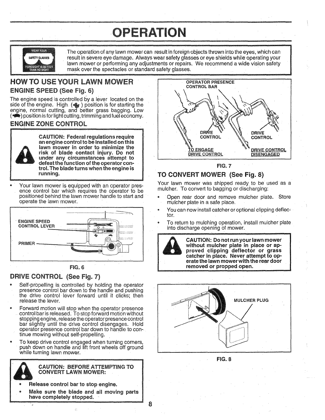
HOW TO USE YOUR LAWN MOWER
ENGINE SPEED (See Fig, 6)
The engine speed is controlled by a lever located on the
side of the engine. High• (4) position is for starting the
engine, normal cutting, and better grass bagging. Low
(_) position isfor light cutting; trimming and fuel economy.
ENGINE ZONE CONTROL
CAUTION: Federal regulations require
an engine control to be installed on this
lawn mower in order to minimize the
risk of blade contact injury. Do not
under any circumstances attempt to
defeat the function of the operator con-
trol. The blade turns when the engine is
running.
Your lawn mower is equipped with an operator pres-
ence control bar which requires the operator to be
positioned behind the lawn mower handle to start and
operate the lawn mower.
ENG,NESPEED _%
PRIMER _ _- ...........[i_ ............
FiG. 6
DRIVE CONTROL (See Fig. 7}
• Self-propelling is controlled by holding the operator
presence control bar down to the handle and pushing
the drive control lever forward until it clicks; then
release the iever.
• Forward motion wifl stop when the operator presence
control bar is released. To stop forward motion without
stopping engine, release the operator presence control
bar slightly until the drive control disengages. Hold
operator presence control bar down to handle to con-
tinue mowing without self-propelling.
• To keep drive control engaged when turning corners,
push down on handle and lift front wheels off ground
while turning lawn mower.
CAUTION: BEFORE ATTEMPTING TO
CONVERT LAWN MOWER:
•Release control bar to stop engine,
-Make sure the blade and aimmoving parts
have completely stopped.
OPERATOR PRESENCE
CONTROLBAR
DRIVE
CONTROL
DRJ_V_ECONTROL DRIVE CONTROL
DI_SENGAGED
FIG. 7
TO CONVERT MOWER (See Fig. 8)
Your lawn mower was shipped ready to be used as a
mulcher. To convert to bagging or discharging:
- Open rear door and remove mulcher plate. Store
mulcher plate in a safe place.
-You can now install catcher or optional clipping deflec-
tot.
- To return to mulching operation, install mulcher plate
into discharge opening of mower.
CAUTION: Do not run your lawn mower
without mulcher plate in place or ap-
proved clipping deflector or grass
catcher in place. Never attempt to op-
erate the lawn mower with the rear door
removed or propped open.
MULCHER PLUG
FiG. 8
OPERATION
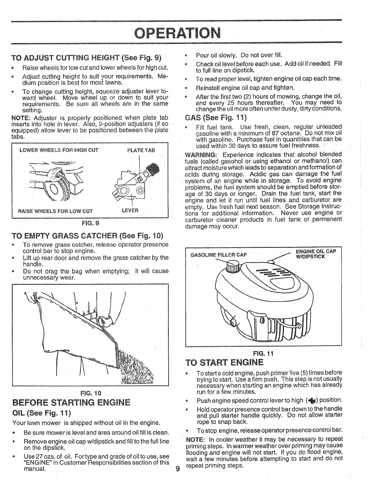
TO ADJUST CUTTING HEIGHT (See Fig. 9}
Raise wheels for low cut and lower wheels for high cut.
oAdjust cutting height to suit your requirements. Me-
dium position is best for most fawns.
- To change cutting height, squeeze adjuster lever to-
ward wheel. Move wheel up or down to suit your
reqLJirements. Be sure alt wheels are in the same
setting.
NOTE: Adjuster is properly positioned when plate tab
inserts into hole in lever. Also, 9-position adjusters (if so
equipped) allow lever to be positioned between the plate
tabs.
LOWER WHEELS FOR H_GH OUT
RAISE WHEELS FOR LOW' OUT
PLATE TAB
LEVER
FIG. 9
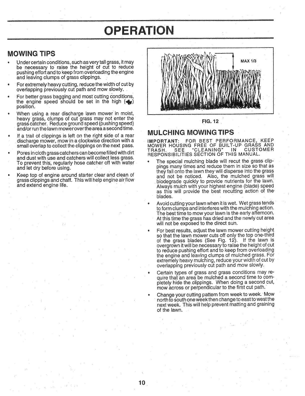
TO EMPTY GRASS CATCHER (See Fig. 10)
To remove grass catcher, release operator presence
control bar to stop engine.
- Lift up rear door and remove the grass catcher by the
handle.
, Do not drag the bag when emptying; it will cause
unnecessary wear.
1
/
FiG. 10
BEFORE STARTmNG ENGINE
OiL (See Fig, 11)
Your lawn mower is shipped without oil in the engine.
• Be sure mower is level and area around oi! fill is clean.
• Remove engine oil cap w/dipstick and fill to the full liRe
on the dipstick.
• Use27 ozs. of oil. For type and grade of oil to use, see
"ENGINE" in Customer Responsibilities section of this
manual. 9
*Pour oil slowly. Do not over fill.
oCheck oil level before each use. Add oil if needed. Fill
to full line on dipstick.
o To read proper level, tighten engine oil cap each time.
o Reinstall engine oil cap and tighten.
o After the first two (2) hours of mowing, change the oil
and every 25 hours thereafter. You may need to
change the oil more often under dusty, dirty conditions.
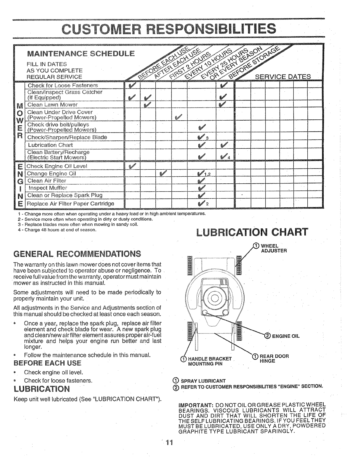
GAS (See Fig. 1!)
o Fill fuel tank, Use fresh, clean, regular unleaded
gasoline with a minimum of 87 octane. Do not mix oil
with gasoline. Purchase fuel in quantities that can be
used within 30 days to assure fuel freshness..
WARNING: Experience indicates that alcohol blended
fuels (called gasohol or using ethanol or methanol) can
attract moisture which leads to separation and formation of
scids during storage. Acidic gas can damage the fuel
system of an engine while in storage, To avoid engine
problems, the fuel system should be emptied before stor-
age of 30 days or longer. Drain the fuel tank, start the
engine and let it run until fue! lines and carburetor are
empty. Use fresh fuel next season. See Storage Instruc-
tions for additional information. Never use engine or
carburetor cfeaner products in fuel tank or permanent
damage may occur.
GASOLINE FILLER CAP ENGINE oIL CAP
W/D!PSTICK
FIG_ 11
TO START ENGINE
* To start a cold engine, push primer five (5) times before
trying to start. Use a firm push. This step is not usually
necessary when starting an engine which has already
run for a few minutes.
, Push engine speed control [ever to high (4) position.
, Hold operator presence control bar down to the handle
and pull starter handle quickly. Do not allow starter
rope to snap back.
*To stop engine, release operator presence contro! bar.
NOTE: In cooler weather it may be necessary to repeat
priming steps, tn warmer weather over priming may cause
flooding and engine will not start. If you do flood engine,
wait a few minutes before attempting to start and do not
repeat priming steps.
OPERATION
MOWING TiPS
•Under certain conditions, such as very ta!l grass, itmay
be necessary to raise the height of cut to reduce
pushing effort and to keep from overloading the engine
and leaving clumps of grass clippings.
•For extremely heavy cutting, reduce the width of cut by
overlapping previously cut path and mow Slowly,
• For better grass bagging and most cutting conditions,
the engine speed should be set in the high (_)
position.
When using a rear discharge lawn mower in moist,
heavy grass, clumps of cut grass may not enter the
grass catcher. Reduce ground speed (pushing speed)
and/or run the lawn mower over the area a secOnd time.
• If a trail of clippings is left on the right side of a rear
discharge mower, mow in a clockwise direction with a
small overlap to collect the clippings on the next pass.
•Pores inctoth grass catchers can become filled with dirt
and dustwith use and catchers will collect less grass.
To prevent this_ regularly hose catcher off with water
and let dry before using.
oKeep top of engine around starter clear and ctean of
grass clippings and chaff. This will help engine airflow
and extend engine life.
MAX 1/3
FIG. t2
MULCHING MOWING TiPS
IMPORTANT: FOR BEST PERFORMANCE, KEEP
MOWER HOUSING FREE OF BUILT-UP GRASS AND
TRASH. SEE "CLEANING ' IN CUSTOMER
RESPONSIBILiTiES SECTION OF THIS MANUAL.
* The special mulching blade will recut the'grass clip-
pings many times and reduce them in size so that as
they fall onto the lawn they will disperse into the grass
and not be noticed. Also, the mulched grass wil!
biodegrade quickly to provide nutrients for the !awn.
Always mulch with your highest engine (blade) speed
as this will provide the best recutting action of the,
blades.
, Avoid cutting your lawn when it is wet. Wet grass tends
to form clumps and interferes with the muiching action.
The best time to mow your lawn is the early afternoon,
At this time the grass has dried and the newly cut area
wili net be exposed to the direct sun.
For best results, adjust the lawn mower cutting height
so that the lawn mower cuts off only the top one-third
of the grass blades (See Fig. 12). tf the fawn is
overgrown it will be necessary to raise the height of cut
to reduce pushing effort and to keep from overloading
the engine and leaving clumps of rnulched grass. For
extrer_ely heavy mulching, reduce your width of cut by
overlapping previously cut path and mow slowly:
oCertain types of grass and grass conditions may re-
quire that an area be mulched a second time to com-
pletely hide the clippings. When doing a second cut,
mow across or perpendicular to the first cut path.
,Change your cutting pattern from week to week. Mow
north tOsouth one week then change to east to west the
next week. This will help prevent matting and graining
of the lawn.
10•
OUSTO RESPON ILITi
FILL IN DATES
AS YOU COMPLETE
REGULAR SERVICE
Check for Loose Fasteners
Cleani_nspect Gra:ss Catcher
(if Equipped)
Clean Lawn Mower
Clean Under Drive Cover
(Power:Propelled Mowers)
Check drive beft/pulleys
.(Power-PropeI_ed Mowers)
ChecWSharpen/RepIace Blade
Lubrication Chart
Clean BattepiiRecharge
Electric Start Mowers)
Check Engine O}! Level
ins Oil
Clean Air Filter
Inspect Muffler
Clean or Replace Spark Plug
Replace Air Fiiter Paper Cartridge
1 - Change more often when operating under a heav,
2 ,- Service more often when ope_>3,ting in diC_y or dusty conditions.
3 - Replace blades more often when mowing in sandy soil.
4 - Charge 48 hours at end of season.
' lead or in high ambient temperatures.
SERVICE DATES
LUBRiCATiON CHART
GENERAL RECOM JIENDATIONS
The warranty on this lawn mower does not cover items that
have been subjected to operator abuse or negligence, To
receive fu IIvalue from the warranty, operator must maintain
mower as instructed in this manual.
Some adjustments will need to be made periodically to
properly maintain your unit.
All adjustments in the Semice and Adjustments section of
this manual should be checked at teast once each season.
Once a year, replace the spark plug, replace air filter
element and cheCk blade for wear. A new spark plug
and clean/new air filter element assures proper air-fuel
mixture and helps your engine run better and last
longer.
Follow the maintenance schedule in this manual.
BEFORE EACH USE
Check engine oil level.
• Check for loose fasteners.
LUBRICATION
Keep unit well lubricated (See "LUBRICATION CHART").
WHEEL
ADJUSTER
ENGINE OIL
REAR DOOR
HANDLE BRACKET HINGE
MOUNTING PiN
OSPRAY LUBRICANT
(_ REFER TO CUSTOMER RESPONSIBILITIES "ENGINE" SECTION,
iMPORTANT: DO NOT OIL OR GREASE PLASTIC WHEEL
BEARINGS: VISCOUS LUBRICANTS WILL ATTRACT
DUST AND DiRT THAT WILL SHORTEN THE LIFE OF
THE SELF LUBRICATING BEARINGS. IF YOU FEEL THEY
MUST BE LUBRICATED, USE ONLY A DRY, POWDERED
GRAPHITE TYPE LUBRICANT SPARINGLY.
11
CUSTO PO ILITIES
LAWN MOWER
Always observe safety rules when performing any mainte-
nance.
TIRES
=Keep tiresfree of gasoline, oil, or insect control chemi-
cals which can harm rubber.
- Avoid stumps, stones, deep ruts, sharp objects and
other hazards that may cause tire damage.
BLADE CARE
For best results, mower blade must be kept sharp.
Replace bent or damaged blades.
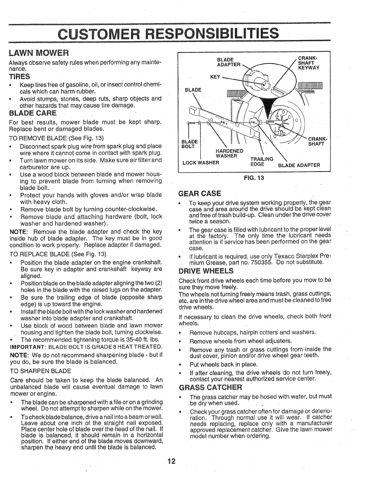
TO REMOVE BLADE (See Fig. 13)
•Disconnect spark plug wire from spark plug and place
wire where it cannot come in contact with spark plug.
•Turn lawn mower on its side. Make sure air filter and
carburetor are up.
• Use a wood block between blade and mower hous-
ing to prevent blade from turning when removing
blade bolt.
• Protect your hands with gloves and/or wrap blade
with heavy cloth.
• Remove blade bolt by turning counter-clockwise..
• Remove blade and attaching hardware (bolt, lock
washer and hardened washer).
NOTE: Remove the blade adapter and check the key
inside hub of blade adapter. The key must be in good
condition to work properly. Replace adapter if damaged.
TO REPLACE BLADE (See Fig. 13)
•Position the blade adapter on the engine crankshaft.
Be sure key in adapter and crankshaft keyway are
aligned.
• Position blade on the blade adapter aligning the two (2)
holes in the bladewith the raised lugs on the adapter.
•Be sure the trailing edge of blade (opposite sharp
edge) is up toward the engine.
• Install the blade bolt with the lock washer and hardened
washer into blade adapter and crankshaft.
• Use block of wood between blade and lawn mower
housing and tighten the blade bolt, turning clockwise.
° The recommended tightening torque is 35-40 ft. Ibs.
IMPORTANT: BLADE BOLT IS GRADE 8 HEATTREATED.
NOTE: We do not recommend sharpening blade - but if
you do, be sure the blade is balanced.
TO SHARPEN BLADE
Care should be taken to keep the blade balanced. An
unbalanced blade will cause eventual damage to lawn
mower or engine.
° The blade can be sharpened with a file or on agrinding
wheel. D0 not attempt to sharpen while on the.mower.
• To check blade balance, drive a nail into a beam orwall.
Leave :about one inch of the straight nail exposed.
Place center hole of blade over the head of the nail. If
blade is balanced, it should remain in a horizontal
position. If either end of the blade moves downward,
sharpen the heavy end until the blade is balanced.
BLADE
BLADE
KEY
CRANK-
SHAFT
KEYWAY
CRANK-
BL SHAFT
B( HARDENED
WASHER TRAILING
LOCK WASHER EDGE BLADE ADAPTER
FIG. 13
GEAR,CASE
- To keep your drive system working properly, the gear
case and area around the drive should be kept clean
and free of trash build-up. Clean under the drive cover
twice a season.
°The gear case is filled with lubricant to the proper level
at the factory. The only time the lubricant needs
attention is if service has been performed on the gear
case.
•If lubricant is required, use only Texaco Starplex Pre-
mium Grease, part no. 750355. Do not substitute,
DRIVE WHEELS
Check front drive wheels each time before you mow to be
sure they move freely.
The wheels not turning freely means trash, grass cuttings,
etc. are in the drive wheel area and must be cleaned to free
drive wheels.
tf necessary to clean the drive wheels, check both front
wheels.
Remove hubcaps, hairpin cotters and washers.
,Remove wheels from wheel adjusters.
• Remove any trash or grass cuttings from inside the
dust cover, pinion and!or drive wheel gear teeth.
•Put wheels back in place.
If after cleaning, the drive wheels do not turn freely,
contact your nearest authorized service center.
GRASS CATCHER
= The grass catcher may be hosed with water, but must
be dry when used.
• Checkyour grass catcher often for damage or deterio-
ration. Through normal use it wifl wear. if catcher
needs replacing, replace only with a manufacturer
approved replacement catcher. Give the lawn mower
model number when ordering.
12
CUSTOM RESPO L|T ES
ENGINE
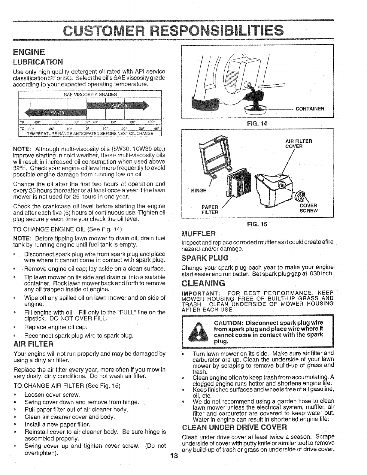
LUBRICATION
Use only high quality detergent oi! rated with AP[ service
classification SF or SG..._etvct the o t s SAE v scos ty grade
according to your expected operating temperature.
SAE VISCOSF_ GRADES
_F r -20 _ 0" 30 _ 32_ 40 _ 60_ 80 _ 100°
°c 30o .,oo 40° ;° 1'o°_ 20" 2o 4;°
TEMPERATURE RANGE ANTICIPATED BEFORE NEXT OIL CHANGE
NOTE: Although mukFviscosity oits (5W30; t0W30 etc,)
improve staring in cold weather, these multi-viscosity oils
will result in increased oil consumption when used above
32°F. Check your engine oil levei more frequently to avoid
possible engine damage from running low on oil.
Change the oil after the first two hours of operation and
every 25 hours thereafter or at least once a year if the lawn
mower is not used for 25 hours in one y®ar.
Check the crankcase oil level before starting the engine
and after each five (5) hours of continuous use. Tighten oil
plug securely each time you check the Oil level.
TO CHANGE ENGINE OIL(see Fig. 14)
NOTE: Before tipping lawn mower to drain oil, drain fue!
tank by running engine until fuel tank is empty.
• Disconnect spark plug wire from spark plug and place
wire where it cannot come in contact with spark plug.
Remove engine oil cap; lay aside on a clean surface.
• Tip lawn mower on its side and drain oil into a suitable
container. Rock Jawn mower back and forth to remove
any oil trapped inside of engine.
, Wipe' off any spilled oil on lawn mower and on side of
engine.
Fill engine with oil. Fill only to the "FULL" line on the
dipstick. DQ NOT OVER FILL,
• Replace engine oil cap.
Reconnect spark plug wire to spark plug.
AIR FILTER
Your engine will not run properly and may be damaged by
using a dirty air filter.
Replace the air filter every year, more often if you mow in
very dusty, dirty conditions. Do not wash air filter.
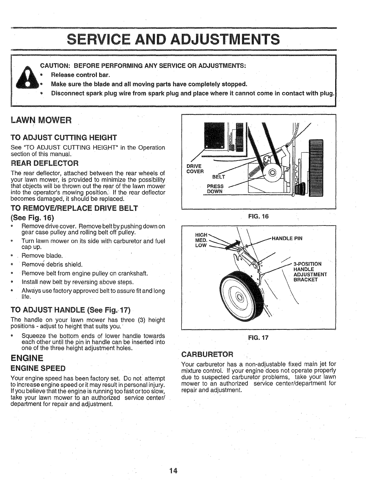
TO CHANGE AIR FILTER (See Fig. 15)
*Loosen cover screw,
Swing cover down and remove from hinge.
o Pul! paper filter out of air cleaner body.
Clean air cleaner cover and body.
install a new paper filter.
® Reinstall cover to air cleaner body. Be sure.hinge is
assembled properly.
® Swing cover up and tighten cover screw. (Do not
overtighten). 13
CONTAINER
FIG. 14
AIR FILTER
COVER
H!NGE
/
PAPER /COVER
FnLTER SCREW
FIG. 15
MUFFLER
Inspect and replace corroded muffler as it could create afire
hazard _nd!or damage.
SPARK PLUG
Change your spark plug each year to make your engine
start easier and run better, Set spark pluggap at .030 inch.
CLEAN NG
IMPORTANT: FOR BEST PERFORMANCE, KEEP
MOWER HOUSIN_ FREE OF BUILT-UP GRASS AND
TRASH. CLEAN UNDERSIDE OF MOWER HOUSING
AFTER EACH USE.
,_ f_. ace_ ._wirewhere !t I
_n{act with the spark
plug. •
• Turn lawn mower on its side. Make sure air filter and
carburetor are up. Clean the underside of your lawn
mower by scraping to remove build-up of grass and
trash.
Clean engine often to keep trash from accumulating. A
c ogged engine runs hotter and shortens engine life.
• Keep finished surfaces and wheels free of all gasoline,
oil, etc.
We do not recommend using a garden hose to clean
lawn mower unless the electrical system, muffler, air
filter and carburetor are covered to keep water out.
Water in engine can result in shortened engine life.
CLEAN UNDER DRIVE COVER
Clean under drive cover at least twice a season. Scrape
underside of cover with putty knife or simifar t0ol to remove
any build-up of trash or grass on underside of drive cover.
SERVIC AND ADJUSTIVi NTS
CAUT|ON: BEFORE PERFORMING ANY SERVICE OR ADJUSTMENTS:
=Release control bar.
Make sure the blade and all moving parts have completely stopped.
, Disconnect spark plug wire from spark plug and place where it cannot come in contact with plug.
LAWN MOWER
TO ADJUST CUTTING HEIGHT
See "TO ADJUST CUTTING HEIGHT" in the Operation
section of this manual.
REAR DEFLECTOR
The rear deflector, attached between the rear wheels of
your lawn mower, is provided to minim=ze the possibility
that objects will be thrown out the rear of the lawn mower
into the operator's mowing position, If the rear deflector
becomes damaged, it should be replaced.
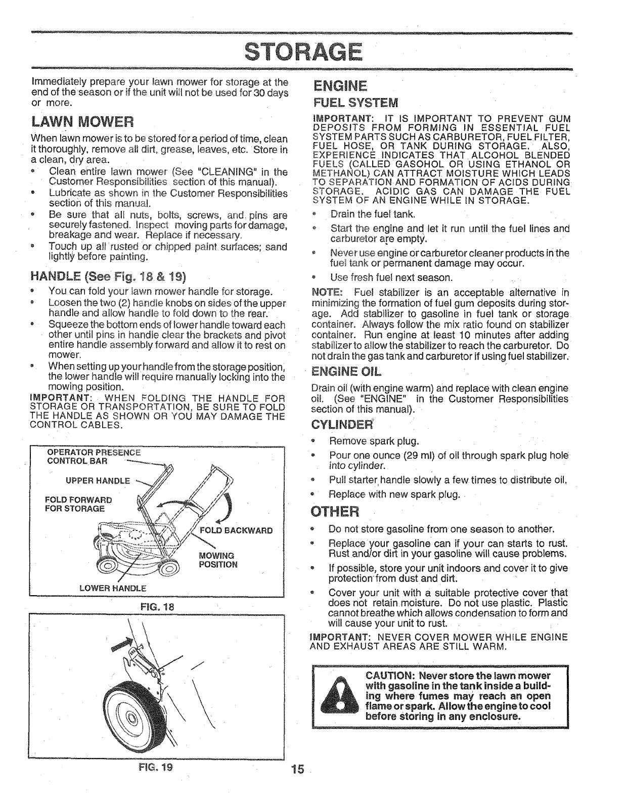
TO REMOVE/REPLACE DRIVE BELT
(See Fig, !6)
= Remove drive cover. Remove belt by pushing down on
gear case pulley and rolling belt off pulley.
o Turn lawn mower on its side with carburetor and fuel
cap up,
Remove blade,
o Remove debris shield.
Remove belt from engine pulley on crankshaft.
Install new belt by reversing above steps.
Always use factory approved belt to assu re fit and long
tife.
TO ADJUST HANDLE (See Fig, !7)
The handle on your lawn mower has three (3) height
positions - adjust to height that suits you.
Squeeze the bottom ends of lower handle towards
each other until the pin in handle can be inserted into
one of the three height adjustment holes.
ENGINE
ENGaNE SPEED
Your engine speed has been factory set. Do not attempt
to increase engine speed orit may result in personal injury.
Ifyou believe tha_tthe eng ne _srunning too fast or too stow,
take your lawn mower to an authorized service center/
department for repair and adjustment.
/
,/
DRIVE
COVER
BELT
PRESS
DOWN
FiG. 16
\PIN
J
f3-POSITION
HANDLE
ADJUSTMENT
BRACKET
\
FiG. 17
CARBURETOR
Your carburetor has a non-adjustable fixed main jet for
mixture control. If your engine does not operate properly
due to suspected carburetor problems, take your lawn
mower to an authorized service center/department for
repair and adjustment.
14
STORAGE
Immediately prepare your lawn mower for storage at the
end of the'season or if the unit will not be used for30 days
or more.
LAWN MOWER
When lawn mower is to be stored for a period of time, clean
it thoroughly, remove ati dirt, grease, leaves, etc. Store in
a clean, dry area.
o Clean entire lawn mower (See "CLEANING" in the
Customer Responsibilities section of this manual).
• Lubricate as shown in the Customer Responsibilities
section of this manual.
Be sure that all nuts, bolts, screws, and, pins are
securefy fastened, inspect moving parts for damage,
breakage and wear. Replace if necessary.
, Touch up all'rusted 0r chipped paint surfaces; sand
lighti_, before painting:
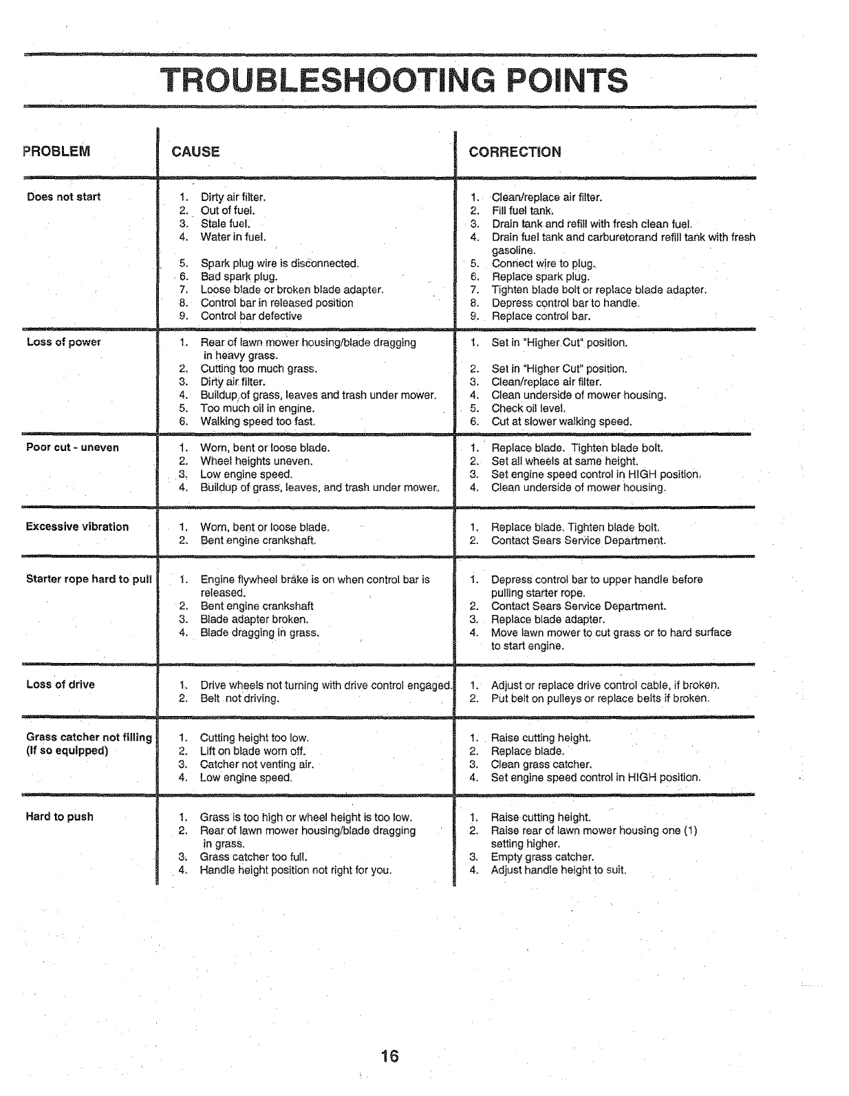
HANDLE (See Fig. t8 & t9)
*You can fold your lawn mower handle for storage.
o Loosen the two (2) handie knobs on sides of the upper
handle and allow handle to fold down to the rear.
Squeeze the bottom ends of lower handle toward each
other until pins in handle clear the brackets and pivot
entir e handle assembly forward and allow it to rest on
mower.
, When setting up your handle from the storage position,
the Iower handle will require manually locking into the
mowing position.
IMPORTANT: WHEN FOLDING THE HANDLE FOR
STORAGE OR TRANSPORTATION, BE SURE TO FOLD
THE HANDLE AS SHOWN OR YOU MAY DAMAGE THE
CONTROL CABLES.
OPERATOR PRESENCE
CONTROL BAR "_--___
UPPER HANDLE
FOLD FORWARD t_(//
FOR STORAGE _%,
LOWER HANDLE
FOLD BACKWARD
MOWING
POSITION
FIG. 18
/
,/
ENGINE
FUEL SYSTEM
iMPORTANT: iT IS IMPORTANT TO PREVENT GUM
DEPOSITS FROM FORMING IN ESSENTIAL FUEL
SYSTEM PARTS SUCH AS CARBURETOR, FUEL FILTER,
FUEL HOSE, OR TANK DURING STORAGE. ALSO,
EXPERIENCE INDICATES THAT ALCOHOL BLENDED
FUELS (CALLED GASOHOL OR USING ETHANOL OR
ME3'_HANOL) CAN ATTRACT MOISTURE WHICH LEADS
TO SEPARATION AND FORMAT ON OF AC DS DUR NG:
STORAGE, ACIDIC GAS CAN DAMAGE THE FUEL
SYSTEM OF AN ENGINE WHILE IN STORAGE.
o Drain the fuel tank,
o Start the engine and let it run until the fuel lines and
carburetor are empty.
o Never use engine or carburetor cleaner products inthe
fue_ tank or permanent damage may occur.
Use fresh fuel next season.
NOTE: Fuel stabilizer is an acceptable alternative in
minimizing the formation of fuel gum deposits during stor-
age. Add stabilizer to gasoline in fuel tank or storage
container. Always follow the mix ratio found on stabilizer
container. Run engine at least 10 minutes after adding
stabilizer to allow the stabilizer to reach the carburetor. Do
not drain the gas tank and carburetor if using fuel stabilizer.
ENG_[NE OIL
Drain oi! (with engine warm) and replace with clean engine
oil (See "ENGINE" in the Customer Responsibilities
section of this manual).
CYUNDER
° Remove spark plug.
Pour one ounce (29 ml) of oil through spark plug hole
into cylinder,
* Pull starter handle slowly a few times to distribute oil,
Replace with new spark plug.
OTHER
o Do not store gasoline from one season to another.
o Replace your gasoline can if your can starts to rust.
Rust and/or dirt in your gasoline will cause problems,
, If possible, store your unit indoors and cover it to give
protection from dust and dirt.
Cover your unit with a suitable protective cover that
does not retain moisture. Do not use plastic. Plastic
cannot breathe which allows condensation to form and
will cause your unit to rust.
IMPORTANT: NEVER COVER MOWER WHILE ENGINE
AND EXHAUST AREAS ARE STILL WARM.
CAUTION: Never store the lawn mower
with gasoline in the tank inside a build-
ing where fumes may reach an open
fiameor spark. AIIowthe engineto cool
before storing in any enclosure.
FmGo_9 15
TROU LESHOOTING POINTS
_ROBLEM
Does not start
CAUSE
1. Dirty air filter.
2. Out of fuel.
3. Stale fuel;
4. Water in fuel.
5. Spark plug wire is disconnected.
• 6. Bad spark piug.
7, Loose blade or broken blade adapter.
8. Contro{ bar in released position
9. Control bar defective
LOss of power 1. Rear of fawn mower housing/blade dragging
in heavy grass.
2. Cutting too much grass.
3. Dirty air fitter.
4. Buildup.of grass, leaves and trash under mower.
5. Too much oi! in engine.
6. Walking speed too fast.
1. Worn. bent orloose bfade.
2. Wheel heights uneven.
: 3_ Low engine speed.
4. Bijildup of grass, leaves, and trash under mower.
Poor cut - uneven
Excessive vibration 1. Worn. bent or loose blade.
2. Bent engine crankshaft.
Starter rope hard to pul| t. Engine flywheel br_ike is on when control bar is
released.
2. Bent engine crankshaft
3. Blade adapter broken.
4. Blade dragging in grass.
Loss of drive
. = _=._=- . .-;
Grass catcher not filling
(If so equipped)
Hard tO push
1. Drive wheels not turning with drive control engaged.
2. Belt notdriving.
1. Cutting height too tow.
2. Lift on blade worn off.
3. Catcher not venting air.
4. Low engine speed.
!. Grass is too high or wheel height is too low.
2. Rear of lawn mower housing/blade dragging
ingrass.
3. Grass catcher too fu!!.
4. Handle Height position not right for you.
CORRECTION
•rr •
t. Clean/replace air filter.
2. Fill fuel tank_
3. Drain tank and refiil with fresh Clean fuel.
4. Drain fuel tank and carburetorand refill tank with fresh
gasoline.
5. Connect wire to plug..
6. Reptace sparkplug.
7. Tighten blade bolt or repiace blade adapter:
8. Depress control bar to handle.
9. Replace control bar.
I. Set in "Higher. Cut" position.
2. Set in "Higher Cut" position.
3. Clean!replace air filter.
4_ Clean underside of mower housing.
5. Check oii level.
6. Cut at slower walking speed.
1. 'Replace blade. Tighteil blade bolt.
2. Set aIl wheels at same height.
3. Set engine speed control in HIGH position,
4. Clean underside of mower housing.
1. Replace blade. Tighten blade bolt.
2. Contact Sears Service Departmer)t.
i. Depress control bar to upper handle before
putling starter rope.
2. Contact Sears Service Department.
3. Replace blade adapter.
4. Move lawn mower to cut grass or to hard surface
to start engine.
1. Adjust or replace drive control cable, if broken,
2. Put belt on pulleys or replace belts if broken.
t. Raise cutting height.
2. Replace blade.
3. Clean grass catcher.
4. Set engine speed control in HIGH position.
I. Raisecutting height.
2. Raise rear of iawn mower housing one (1)
setting higher.
3. Empty grass catcher.
4. Adjust handle height to suit.
16

SERVICE NOTES
17
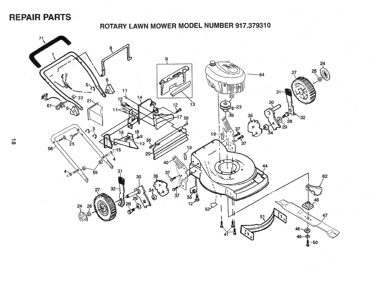
REPAIR PARTS
QO
58 25
5
59
27
24- 26
ROTARY LAWN MOWE RMODEL NUMBER 917.379310
11
4
18
30
56
•
I
12 13
56
37
36
22
27
35
28
44
-50
REPAIR PARTS
ROTARY LAWN MOWER MODEL NUMBER 917o379310
_O
KEY PART
NO. NO
1 145640X479
2 158921
4 150502
5 151517
6 87692
7 STD54t425
8 145794
9 147690
11 128415
12 STD512505
13 146337
14 700483X479
t5 700365X479
16 133190X479
!7 140661X479
!8 150050
19 51793
20 140540
21 150425
22 85543
23 87677
24 150181
25 131959
26 83923
27 150341
28 142748
29 62335
30 145937X004
31 701037
32 850862X004
33 73510400
34 14663Q
35 146233
36 146234
37 150078
39 153300X479
40 t53301X479
DESCRIPTION
Upper Handle
Engine Zone Control Cable
Handle Bolt, Quick
Cable Clip
Handle Knob
Locknut 1/4-20
Control Bar
Rear Door Kit
Pop Rivets
Hex Tapping Screw I/4-20 x t/2
Seal
Back Plate
Side, Baffle
Discharge Baffle
Rear Baffle
Screw
Hairpin Cotter
Rear Skirt
Mulcher Plug
Engine Pulley
HFPro Key #505
Hubcap
Handle Bolt
Flange Nut
Wheel & Tire Assembly
Shoulder Bolt 3/8q6 x 1
Belleville Washer
Axle Arm Assembly
Selector Knob
Selector Spring
Keps Nut i/4-20
Spacer
Wheel Adjusting Bracket (Left)
Wheel: Adjusting Bracket (Right)
'Thread Cutting Screw 5/16-!8 x 3/4
Handte Bracket Assembly (Left)
Handle Bracket Assembly (Right)
KEY PART
NO. NO DESCRIPTION
41
44
46
47
48
49
50
51
52
55
56
58
59
61
62
64
150406
48422
851514
141114
851074
850263
851084
700869X479
85463
751592
88652
151723X479
73990500
132001
134612
7t 155890
-- 159060
Hex Head Thread Rolling Screw 3/8-16 x 1_1/8
Lawn Mower Housing (Incl. Key #14,15,5t & 52)
Blade Adapter
Blade 22"
Hardened Washer
Helical Washer 3/8-24 x t-3/8 Grd. 8
Hex Head Machine Screw 3/8-24 x t-3/8 Grd. 8
Front Baffle
Danger Decal
Locknut 3/8-16
Hinge Sc[ew
Lower Handle
Hex Nut
Rope Guide
Debris Shield
Engine (See Breakdown)
Craftsman 143.976610
Foam Grip
OwneCs Manual
Available accessories not included with lawn mower:
7__t_33723 High Wheel Kit
7_! 33623 Gas Can (2.5 gal.)
71__:33500 Fuel Stabilizer
7_!133027 SAE 30W Oil (27 oz.)
71133417 Dust Shield
7_! 333t6 Mower Cover
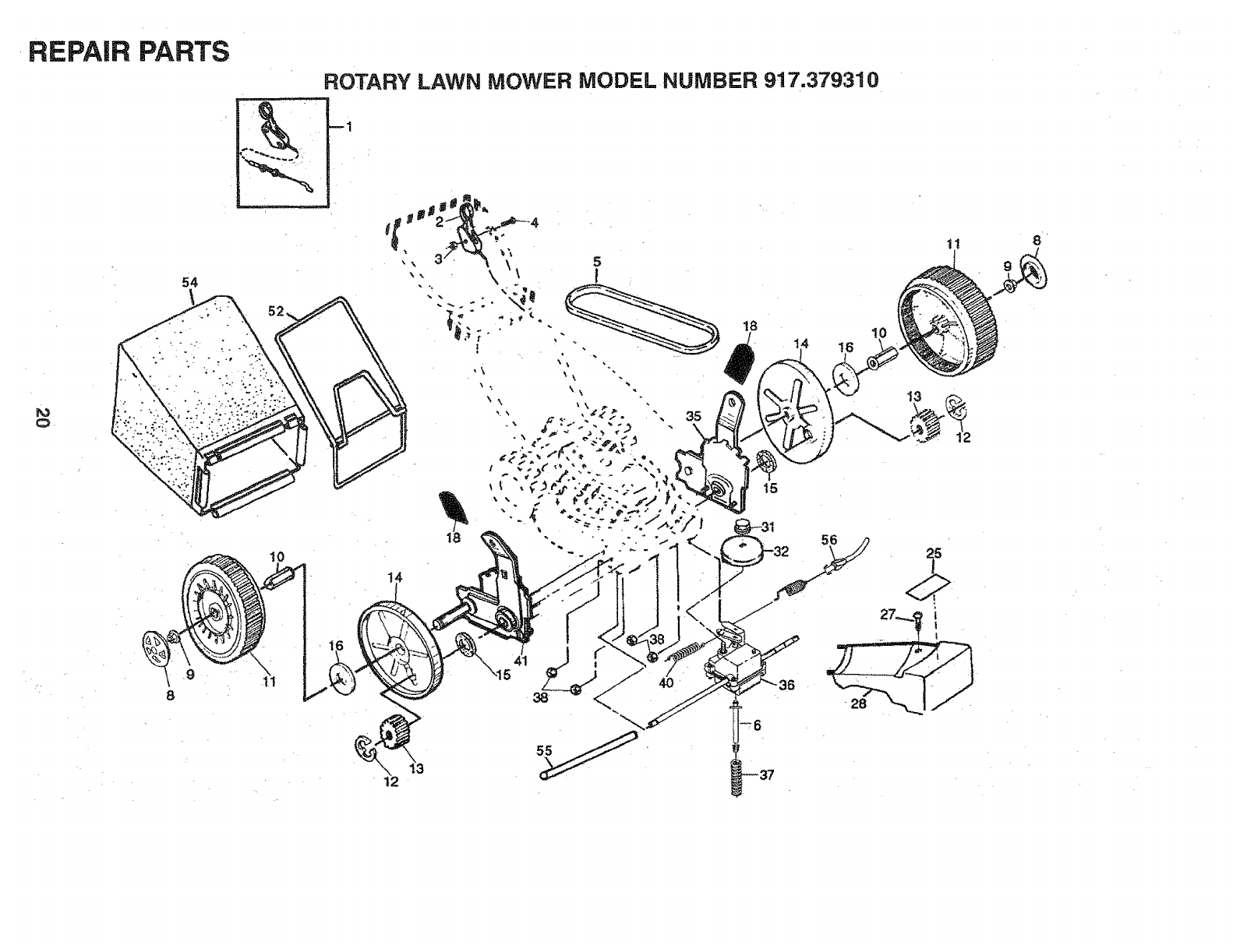
REPAIR PARTS
54
8
8
ROTARY LAWN MOWER MODEL NUMBER 917.37931
18
35
\
18
15
12
0
11
10
8
REPAIR PARTS
ROTARY LAWN MOWER MODEL NUMBER 917.379310
=t
t,o
KEY PART
NO. NO.
1 48385
2 148312
3 63601
4 144929
5 146527
6 15O495
8 150182
9 145212
10 88446
11 150340
12 12000058
t3 137054
t4 88080
15 88118
16 67725
DESCRiPTiON
Drive Head Kit
Drive Control
Locknut #10-24
Hex Washer Head Screw !/4-20 x 2.12
VoBelt
Spring Retainer
Hubcap
Flange Nut
Nylon Bushing
Wheel & Tire Assembly
E:Ring
Pinion
Dust Cover
Felt Washer
Washer t/2 x 1-1/2 × .134
KEY PART DESCRiPTiON
NO. NO
18 701037 Selector Knob
25 152903 Drive Cover Decal
27 143603 Hex Washer Head Screw #10_24 x 3/4
28 154990 Drive Cover
31 t32010 Hex Flange Nut
32 137052 Drive Pulley
35 t53372 Wheel Adjuster Assembly (Left)
36 70251-t Gear Case Assembly
37 137090 Spring
38 STD541425 Hex Locknut 1/4-20
40 75192 Spring
4t 153373 Wheel Adiuster Assembly (Right)
52 150224 Catcher Frame
54 t50257 Grassbag Assembly
55 860t2 Driveshaft Cover
56 48386 Drive Control Cable Kit
REPAIR PARTS
ROTARY LAWN MOWER -= MODEL NO. 917,379310
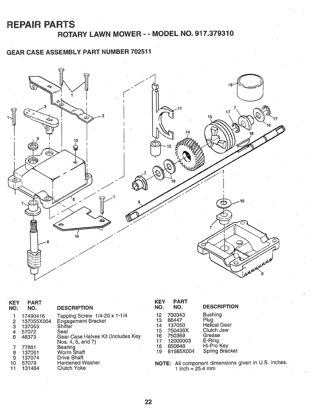
GEAR CASE ASSEMBLY PART NUMBER 702511
lO
15
7
\
17 7\
lO
18
KEY PART
NO_ NO.
1 17490416
2 137055X004
3 137053
4 57072
6 48373
7 77881
8 137051
9 137074
10 57079
11 131484
DESCRIPTION
Tapping Screw 1/4-20 x 1-1/4
Engagement Bracket
Shifter
Seat
Gear Case Halves Kit (Includes Key
Nos. 4, 5, and 7)
Bearing
Worm Shaft.
Drive Shaft
Hardened Washer
Clutch Yoke
KEY PART
NO. NO. DESCRIPTION
12 700343 Bushing
13 86447 Plug
14 137050 Helical Gear
15 750436X Clutch Jaw
16 750369 Grease
17 12000003 E-Ring
18 850848 Hi-Pro Key
19 81585X004 Spfing Bracket
NOTE: AI! component dimensions given in U.S. inches,
1inch = 25.4 mm
22
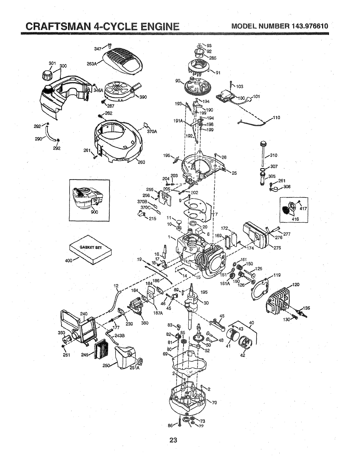
CRAFTSMAN 4..CYCLE ENGINE MODELNUMBER143.976610
301 300 263Af
_2s7
/
292 261 \
370A
416 j
277
350
23g
187A
38O
45
Ig5
151A
23
CRAFTSMAN 4-CYCLE ENGINE MODELNUMBER143.976610
KEY PART
NO. NO, DESCRBPTtON
1 36177
2 27652
6 36059
7 36005A
9 590568
10 36002
11 36003
12 32447
14 28277
15 36006
I6 36008
17 31335
t8 651018
19 36103
20 36010
25 36186
26 650802
30 36185
40 40004
40 40005
41 36070
4! 36071
42 40006
42 40007
43 20381
45 36023A
46 32610A
48 36030
50 36031A
52 29914
69 36032A
70 36194
72 30572
73 28833
75 36010
80 30574A
81 30590A
82 30591
83 36057
85 36034
86 650924
89 611154
90 611155
9I 611156
92 650815
93 650816
100 34443A
101 610118
103 651007
110 36054
119 36061
120 36187
125 36471
125 36472
126 29314B
126 29315C
130 6021A
135 35395
I50 31672
151 31673
151A 40016
!69 27234A
172 32755
174 30200
177 650925A
I84 , 36183
186 36009
t87A 36195
Cylinder (incl. 2,t0,12,20 & I25)
Dowel Pin
Breather Eiement
* Breather Cover & Gasket
Screw, 10-24 x 3/4"
Breather Va ve Body
Check Valve
Breather Tube
Flat Washer
Governor Rod (Machined)
Governor Lever
Governor Lever Clamp
Screw, Torx T-15, 8-32 x t _}/64"
Governor Spring
Oil Seall
Blower Housing Baffle Ass'y.
nclJ95)
crew, I/4.-20 x 5/8 _'
Crankshaft
Piston,Pin,Ring Set (Std.)
Piston,Pin Ring Set (.010OS)
Piston & Pin Ass'y.(Std.) (incl. 43)
Piston & Pin Ass',/.
(.010 OS)(lnc!.43)
Ring Set (Std.)
Ring Set (o010 OS)
Piston Pin Retaining Ring
Connecting Rod Ass'y. (Incl. 46)
Connecting Rod Bott
Valve Lifter
Camshaft (MCR)
Oil Pump Ass'y.
* Mounting Flange Gasket
Mounting Flange (incl. 72 thru 85)
Oil Drain Plug (Incl. 73)
Drain Plug Gasket
Oil Seal
.Governor Shaft
Washer
Governor Gear Ass'y. (lnci.81)
Governor Spool
Idler Gear
Screw, 1/4-20 X I-9/16"
Flywheel Key
Flywheel
Flywheel Fan
Belteville Washer
Flywheel Nut
Solid State Ignition
Spark Plug Cover
Screw, Torx T-15, 10_24 x ! 5/16"
Ground Wire
* Cylinder Head Gasket
Cylinder Head
ExhauSt Valve (Std.!, (incl. t 51)
ExhauSt Valve (1/32 bS)
Intake Valve (Std.) (Incl. 151)
Intake Valve (1/32" OS)
Screw, 5/16-!8 X i-1/2"
Resistor Spark Plug (RJ19LM)
Valve Spring
Lower Valve Spring Cap
Intake Valve Seal
* Valve Spring Box Gasket "
Valve Spring Box Cover
Screw, 10-24 x 9/16"
Carburetor Mounting Stud
Carburetor Gasket
Governor Link
Air Baffle 24
DESCRIPTION
190 36013
191A 36012
t92 36016
t93 36015
I94 36014
195 610973-
198 36017
!99 36018
202 36482
203 31342
204 651029'
205 651030
215 36051
239 36048
240 36190
243B 651041
245 36046
250 36191
251 650928
251A 650933
255 36193
256 650983
260 36188
261 650737
262 650929
263A 36192
275 36107
276 36043
277 650927
285 34449A
287 650926
290 29774
292 26460
300 36189
301 36246
305 36063
307 35499
308 36040
310 36064
346A 28763
347 650898A
350 36045
370A 36261
370B 36155
370C 36861
380 640020
390 590702
400 36062C
416 36085
417 650760
900
900
Brake Lever Ass'y.
Brake Control Lever
Brake Control Lever Link
Brake Spring
Retaining Ring
Terminal Ass'y.
Brake Control Lever Spring
Brake Lever Bushing
Compression Spring
Compression Spring
Screw, 5-40 X 7/16
Screw, Torx T-10, 6-32 x 17/32"
Control Knob
* Carburetor To Air Cleaner Gasket
Air Cleaner Body (Incl.239 & 350)
Air Cleaner Stud
Air Cleaner Filter
Air Cleaner Cover
Lock Nut t/4-20
Wing Nut, t/4-20
Control Plate
Screw, 8-32 x 2t/64"
Blower Housing ,
Screw, 1/4-20 x 1/2
Screw, 1/4-20 x l 1/16"
Starter Grill
Muffler
Locking Plate :.
Screw, 5/6-18 x 2-11/32"
Starter Cup
Screw, 8-32 x 2t/64"
Fuel Line
Fuel Line Clamp
Fuel Tank (Incl. 301)
Fuel Cap .
Oil Fill Tube
"O, Ring
Fitt Tube Clip
Dipstick
Screw, I0-32 x 35/64"
Screw, 10-32 x 27/32"
Primer
Lubrication Decal
Control Decal
Primer Decal
Carburetor (incl. 184,239)
Rewind Starter
Gasket Set
ncl. Items Marked* in Notes)
park Arrestor Kit
(Incl. 4i 7)(Optional)
Screw, 8-32 x 3/8' (Optional)
Replacement Engine 750792B
order from 71-999
Replacement S/B 750797,
order from 7!-999
RPM High 2900 to 3200
RPM Low 2450 to 2750
(NOTE: This engine could have been built with 590739
starter. Refer to the design of the rope pulley strength
ribs for part identification. Individual starter parts do not
interchange.). Incl.part #'s 27234A (1),28833 (1),
36005A (I), 36032A (1), 36035 (1), 36048 (1), 36061
(1), 36183 (2), 696088 Instruction sheet (1) .
NOTE: All component dimensions given in U.S. inches
1 inch = 25.4 mm
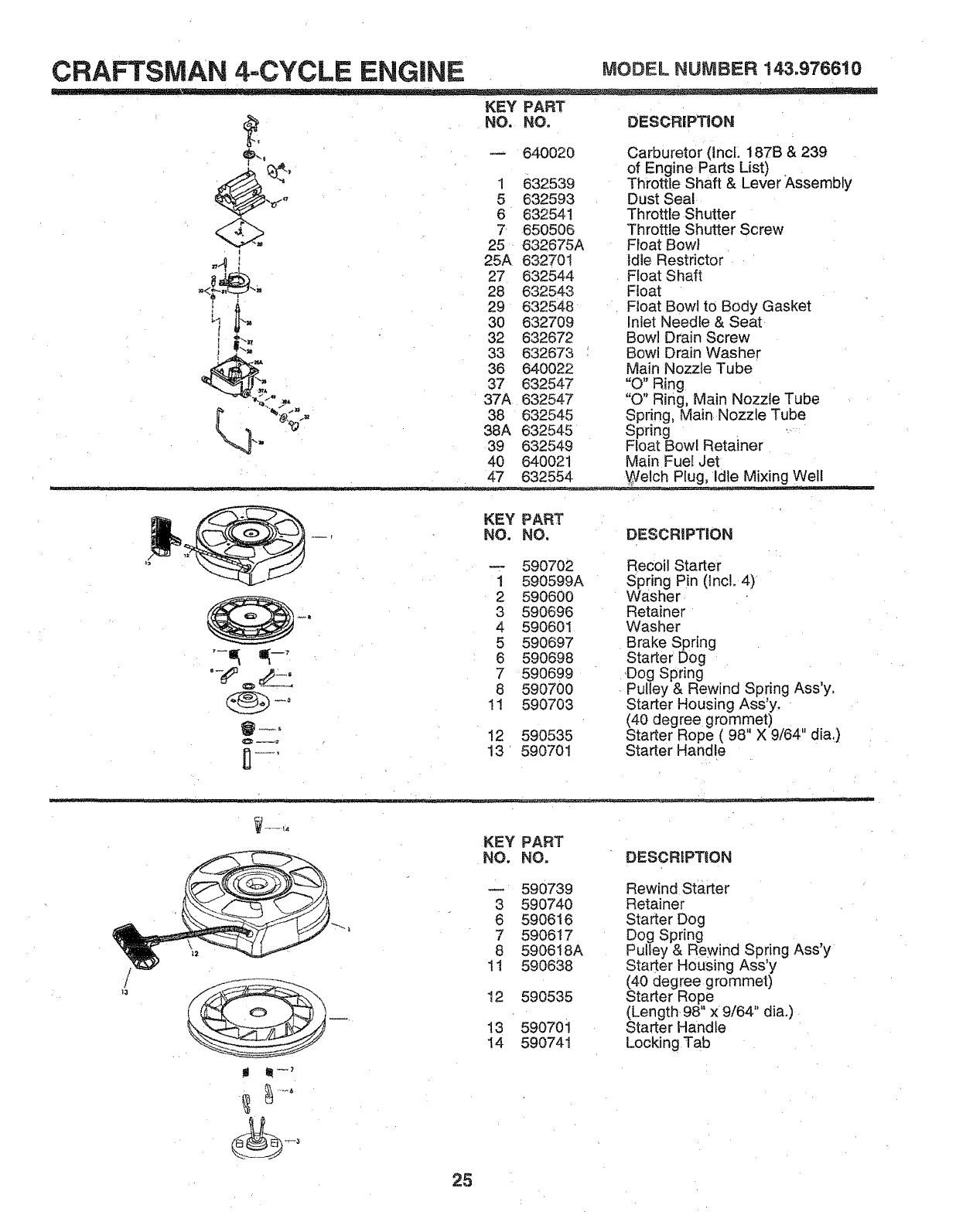
CRAFTSMAN 4=CYCLE ENGINE MODELNUMBER143o976610
KEY PART
I
"4 I
i'_ _
NO. NO. DESCRiPTiON
-- 640020 Carburetor (IncL 187B & 239
of Engine Parts List)
1 632539 Throttle Shaft & Lever Assembly
5 632593 Dust Seal
6 632541 Throttle Shutter
7 650506 Throttle Shutter Screw
25 632675A Float Bowl
25A 632701 tdie Restrictor
27 632544 Float Shaft
28 632543 Float
29 632548 Float Bowl to Body Gasket
30 632709 Inlet Needle & Seat
32 632672 Bowl Drain Screw
33 632673 Bowl Drain Washer
36 640022 Main Nozzle Tube
37 632547 "O" Ring
37A 632547 "O" Ring, Main Nozzle Tube
38 632545 Spring, MainNozzle Tube
38A 632545 Spring
39 632549 Float Bow[ Retainer
40 640021 Main Fuel Jet
...... 47 632554 \gelch Plug, Idle Mixing Well
KEY PART
NO. NO. DESCRiPTiON
-- 590702 Recoil Starter
1 590599A Spring Pin (Incl. 4)
2 590600 Washer
_. 3 590696 Retainer
4 590601 Washer
5 590697 Brake Spring
"-_ _'6 590698 Starter Dog
7 590699 Dog Spring
.__€_a_=_ 8 590700 Pulley & Rewind Spring Ass'y.
(_° 1! 590703 Starter Housing Ass'y.
(40 degree grommet) ,,
__; 12 590535 Starter Rope (98 X 9/64 dia.)
n--_, 13 590701 Starter Handle
U
KEY PART
NO. NO. DESCRIPTeON
mlll1-7
590739 Rewind Starter
3 590740 Retainer
6 590616 Starter Dog
7 590617 Dog Spring
8 590618A Pulley & Rewind Spring Ass'y
11 590638 Starter Housing Ass'y
(40 degree grommet)
12 590535 Starter Rope
(Length 98" x 9/64" dia.)
13 590701 Starter Handle
14 590741 Locking Tab
25
OWNER'S
AN AL
MODEL NO,
917o379310
iF YOU NEED
REPAIR SERVICE
OR PARTS:
FOR REPAIR SERVICE, CALL
THIS TOLL FREE NUMBER:
1-800=4-REPAIR
(1-800-473=7247}
FOR REPLACEMENT PARTS
INFORMATION AND
ORDERING, CALL THIS
TOLL FREE NUMBER:
1-800-FON-PART
(1-800-366-7278)
lilRll
6.6 HORSEPOWER 22"
POWER PROPELLED
ROTARY LAWN MOWER
Each lawn mower has its own model number. Each en-
gine has its own model number.
The mode! number for your lawn mower will be found on a
decal attached to the rear of the tawnmower housing.
The model number for your engine wilt be found on the
blower housing of the engine.
All parts listed herei_ may be ordered from any Sears,
Roebuck and Co, Service Center/Department and most
Retail Stores.
WHEN ORDERING REPAIR PARTS, ALWAYS GIVE THE
FOLLOWING iNFORMATiON:
*PRODUCT- LAWN MOWER
MODEL NUMBER -917.379310
- ENGINE MODEL NO=- 143.976610
- PART NUMBER
- PART DESCRIPTION
Your Sears merchandise has added value when you
consider Sears has service units nationwide staffed with
Sears trained technicians.., professional technicians
specifically trained to insure that we meet our pledge to
you, we service what we sell.
26
