CRAFTSMAN Snowthrower, Gas Manual L0909441
User Manual: CRAFTSMAN CRAFTSMAN Snowthrower, Gas Manual CRAFTSMAN Snowthrower, Gas Owner's Manual, CRAFTSMAN Snowthrower, Gas installation guides
Open the PDF directly: View PDF ![]() .
.
Page Count: 48
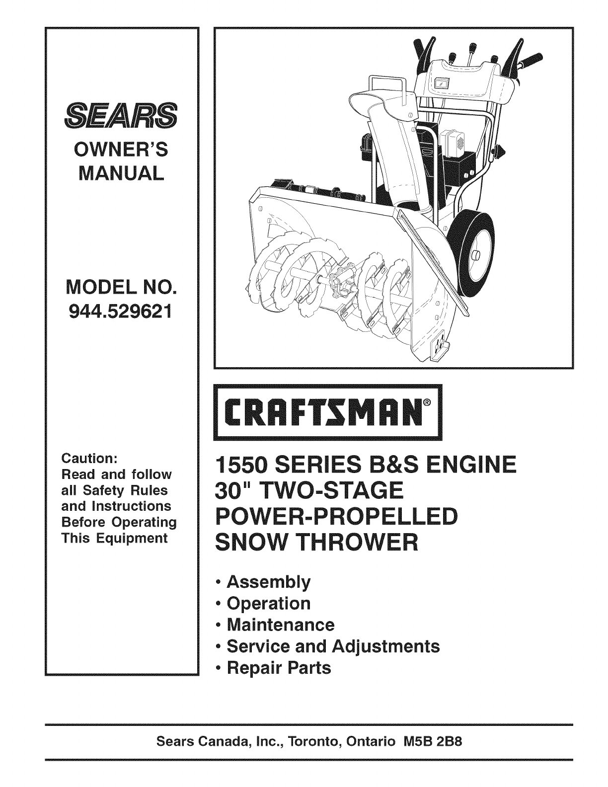
OWNER'S
MANUAL
MODEL NO.
944.529621
Caution:
Read and follow
all Safety Rules
and instructions
Before Operating
This Equipment
!
1SE IES E
" TWO-STAGE
POWE -P LLE
OW TH
•Assembly
• Operation
•Maintenance
• Service and Adjustments
• Repair Parts
E
Sears Canada, inc., Toronto, Ontario MSB 2B8
iMPORTANT
Safe Operation Practices for Walk-Behind Snow Throwers
This snow thrower is capable of amputating hands and feet and throwing objects.
Failure to observe the following safety instructions could result in serious injury.
&Look for this symbol to point out ira=
portant safety precautions. It means
CAUTION!!! BECOMEALERT!!! YOUR
SAFETY IS INVOLVED.
&WARNING: Always disconnect spark
plug wire and place it where it cannot
contact plug in order to prevent acci=
dental starting when setting up, trans-
porting, adjusting or making repairs.
WARNING: This snow thrower is for
use on sidewalks, driveways and other
ground level surfaces. Caution should
be exercised while using on sloping sur=
faces. Do not use snow thrower on
surfaces above ground level such as
roofs of residences, garages, porches
or other such structures or buildings.
&WARNING: Snow throwers have ex=
posed rotating parts, which can cause
severe injury from contact, or from ma=
terial thrown from the discharge chute.
Keep the area of operation clear of all
persons, small children and pets at all
times including startup.
CAUTION: Muffler and other engineparts become extremely hot during
operation and remain hot after engine
_has stopped. To avoid severe burns oncontact, stay away from these areas.
&WARNING: Engine exhaust, some of
its constituents, and certain vehicle
components contain or emit chemi=
cals known to the State of California
to cause cancer and birth defects or
other reproductive harm.
Training
1. Read, understand and follow all instructions on the
machine and in the manual(s) before operating this
unit. Be thoroughly familiar with the controls and the
proper use of the equipment. Know how to stop the
unit and disengage the controls quickly.
2. Never allow children to operate the equipment. Never
allow adults to operate the equipment without proper
instruction.
3. Keep the area of operation clear of all persons, par-
ticularly small children.
4. Exercise caution to avoid slipping or falling, especially
when operating the snow thrower in reverse.
Preparation
1. Thoroughly inspect the area where the equipment is
to be used and remove all doormats, sleds, boards,
wires, and other foreign objects.
2. Disengage all clutches and shift into neutral before
starting the engine (motor).
3. Do not operate the equipment without wearing adequate
winter garments. Avoid loose fitting clothing that can
get caught in moving parts. Wear footwear that will
improve footing on slippery surfaces.
4. Handle fuel with care; it is highly flammable
(a) Use an approved fuel container.
(b) Never add fuel to a running engine or hot engine.
(c) Fill fuel tank outdoors with extreme care. Never fill
fuel tank indoors.
(d) Never fill containers inside a vehicle or on a truck
or trailer bed with a plastic liner. Always place
containers on the ground, away from your vehicle,
before filling.
(e) When practical, remove gas-powered equipment
from the truck or trailer and refuel it on the ground.
If this is not possible, then refuel such equipment
on a trailer with a portable container, rather than
from a gasoline dispenser nozzle.
5.
.
7.
.
(f) Keep the nozzle in contact with the rim of the fuel
tank or container opening at all times, until refueling
is complete. Do not use a nozzle lock-open device.
(g) Replace gasoline cap securely and wipe up spilled
fuel.
(h) If fuel is spilled on clothing, change clothing im-
mediately.
Use extension cords and receptacles as specified by
the manufacturer for all units with electric drive motors
or electric starting motors.
Adjust the collector housing height to clear gravel or
crushed rock surface.
Never attempt to make any adjustments while the
engine (motor) is running (except when specifically
recommended by manufacturer).
Always wear safety glasses or eye shields during op-
eration or while performing an adjustment or repair to
protect eyes from foreign objects that may be thrown
from the machine.
2
Operation
1. Do not put hands or feet near or under rotating parts.
Keep clear of the discharge opening at all times.
2. Exercise extreme caution when operating on or cross-
ing gravel drives, walks, or roads. Stay alert for hidden
hazards or traffic.
3. After striking a foreign object, stop the engine (motor),
remove the wire from the spark plug, disconnect the
cord on electric motors, thoroughly inspect the snow
thrower for any damage, and repair the damage before
restarting and operating the snow thrower.
4. If the unit should start to vibrate abnormally, stop the
engine (motor) and check immediately for the cause.
Vibration is generally a warning of trouble.
5. Stop the engine (motor) whenever you leave the oper-
ating position, before unclogging the collector/impeller
housing or discharge chute, and when making any
repairs, adjustments or inspections.
6. Whencleaning,repairingorinspectingthesnowthrower,
stoptheengineandmakecertainthecollector/impel-
ler andall movingpartshavestopped.Disconnect
thesparkplugwireandkeepthewireawayfromthe
plug.topreventsomeonefromaccidentallystartingthe
engine.
7. Donotruntheengineindoors,exceptwhenstarting
theengineandfortransportingthesnowthrowerinor
outof thebuilding.Opentheoutsidedoors;exhaust
fumesaredangerous.
8. Exerciseextremecautionwhenoperatingonslopes.
9. Neveroperatethesnowthrowerwithoutproperguards,
andothersafetyprotectivedevicesinplaceandwork-
ing.
10.Neverdirectthe dischargetowardpeopleor areas
wherepropertydamagecanoccur.Keepchildrenand
othersaway.
11.Donotoverloadthemachinecapacitybyattempting
toclearsnowattoofasta rate.
12.Neveroperatethemachineat hightransportspeeds
onslipperysurfaces.Lookbehindandusecarewhen
operatinginreverse.
13.Disengagepowertothecollector/impellerwhensnow
throweristransportedornotinuse.
14.Useonlyattachmentsandaccessoriesapprovedby
themanufacturerofthesnowthrower(suchaswheel
weights,counterweights,orcabs).
15.Neveroperatethesnowthrowerwithoutgoodvisibility
orlight.Alwaysbesureofyourfooting,andkeepafirm
holdonthehandles.Walk;neverrun.
16.Nevertouchahotengineormuffler.
CONGRATULATIONSonyourpurchaseof a newsnow
thrower.Ithasbeendesigned,engineeredandmanufac-
turedtogivebestpossibledependabilityandperformance.
Shouldyouexperienceanyproblemyoucannoteasily
remedy,pleasecontactyournearestauthorizedservice
center.Wehavecompetent,well-trainedtechniciansand
thepropertoolstoserviceorrepairthisunit.
Pleasereadandretainthismanual.Theinstructionswill
enableyoutoassembleandmaintainyoursnowthrower
properly.Alwaysobservethe"SAFETYRULES".
SERIALNUMBER:
DATEOFPURCHASE:
THEMODELANDSERIALNUMBERSWILLBEFOUND
ONADECALATTACHEDTOTHEREAROFTHESNOW
THROWERHOUSING.
YOUSHOULDRECORDBOTHSERIALNUMBERAND
DATEOFPURCHASEANDKEEPINASAFEPLACE
FORFUTUREREFERENCE.
Clearing a Clogged Discharge Chute
Hand contact with the rotating impeller insidethe discharge
chute is the most common cause of injury associated with
snow throwers. Never use your hand to clean out the dis-
charge chute. To clear the chute:
1. SHUT THE ENGINE OFF!
2. Wait 10 seconds to be sure the impeller blades have
stopped rotating.
3. Always use a clean-out tool, not your hands.
Maintenance and Storage
1. Check shear bolts and other bolts at frequent intervals
for proper tightness to be sure the equipment is in safe
working condition.
2. Never store the machine with fuel in the fuel tank
inside a building where ignition sources are present
such as hot water heaters, space heaters, or clothes
dryers. Allow the engine to cool before storing in any
enclosure.
3. Always refer to operator's manual for important details
if the snow thrower is to be stored for an extended
period.
4. Maintain or replace safety and instruction labels, as
necessary.
5. Run the machine a few minutes after throwing snow
to prevent freeze-up of the collector/impeller.
PRODUCT SPECIFICATIONS
Gasoline Capacity 3.0 Quarts (2,84 Liters)
and Type: Unleaded Regular only
Oil Type SAE 5W-30 or 10W-30
(API SG=SL): Synthetic SAE 5W-30
Oil Capacity: 28 Ounces (0,8 Liters)
Spark Plug:
Gap:
I
Champion QC12YC
0.030" (0,762 mm)
CUSTOMER RESPONSIBILITIES
• Read and observe the safety rules.
•Follow a regular schedule in maintaining, caring for
and using your snow thrower.
• Follow the instructions under "Maintenance" and "Stor-
age" sections of this owner's manual.
TA OF CONTENTS
SAFETY RULES ........................................................ 2=3
PRODUCT SPECIFICATIONS ...................................... 3
CUSTOMER RESPONSIBILITIES ................................ 3
WARRANTY .................................................................. 4
ASSEMBLY /PRE=OPERATION ............................... 5=8
OPERATION ............................................................ 9-14
MAINTENANCE SCHEDULE ..................................... 15
MAINTENANCE ..................................................... 154 6
SERVICE AND ADJUSTMENTS ........................... 17-19
STORAGE ................................................................... 20
TROUBLESHOOTING ................................................ 21
REPAIR PARTS ..................................................... 22-40
GENERAL: Craftsman products are warranted to be free from defects in materials or workmanship for a specific time period
as set-out below (the "Warranty Period"). Warranties extend to the original purchaser of a Craftsman product only. Purchases
made through an online auction or through any website other than www.sears.ca are excluded. The relevant Warranty Period
commences on the original date of purchase. Within this period, SEARS CANADA, Inc. wilt, at its sole option, repair or replace
any products or components which fail in normal use. Such repairs or replacement will be made at no charge to the customer for
parts or labor, provided that the customer shall be responsible for any transportation cost.
EXCLUSIONS: This warranty does not cover failures due to normal wear, abuse, misuse, neglect (including but not limited to
the use of stale fuel, dirt, abrasives, moisture, rust, corrosion, or any adverse reaction due to improper storage or use habits),
improper maintenance or failure to follow maintenance guidelines and/or instructions, failure to operate the product in accordance
with the owner's manual or any additional instructions or information provided at the time of purchase or in subsequent
communications with the original purchaser, accident or unauthorized alterations or repairs made or attempted by others. Also
excluded from warranty coverage -except as provided below -are the following: maintenance, adjustments, components subject
to wear including but not limited to: cosmetic components, belts, blades, blade adapters, bulbs, tires, filters, guide bars, lubricants,
seats, grips, recoil assy's, saw chains and bars, trimmer lines and spools, spark plugs, starter ropers and tines, and discoloration
resulting from ultraviolet light. Any product missing the model and/or serial number identification label will be disqualified from
coverage under this warranty.
REPAIRS: Repairs have a 90 day warranty. If the defective product is still within the Warranty Period, then the new warranty is 90
days from the date of repair or to the end of the original Warranty Period, whichever period is longer.
DISCLAIMERS: THE WARRANTIES AND REMEDIES CONTAINED HEREIN ARE EXCLUSIVE AND IN LIEU OF ALL OTHER
WARRANTIES, WHETHER ORAL OR WRITTEN (OTHER THAN AS STATED HEREIN), AND WHETHER EXPRESS, IMPLIED
OR STATUTORY, INCLUDING BUT NOT LIMITED TO ANY THIS WARRANTY GIVES YOU SPECIFIC LEGAL RIGHTS, WHICH
MAY VARY FROM PROVINCE TO PROVINCE.
IN NO EVENT SHALL SEARS BE LIABLE FOR ANY INCIDENTAL, SPECIAL, INDIRECT OR CONSEQUENTIAL DAMAGES,
WHETHER RESULTING FROM THE USE, MISUSE OR INABILITY TO USE THE PRODUCT OR FROM DEFECTS IN THE
PRODUCT. THE EXCLUSIONS IN THIS PARAGRAPH SHALL NOT APPLY IN JURISDICATIONS WHERE APPLICABLE LAW
DOES NOT ALLOW FOR THE EXCLUSION OF INCIDENTAL OR CONSEQUENTIAL DAMAGES. IN SUCH JURISDICTIONS,
THIS PARAGRAPH SHALL NOT APPLY, BUT THE REMAINING PROVISIONS OF THIS DOCUMENT SHALL REMAIN VALID.
SEARS retains the exclusive right to repair or replace the product or offer a full refund of the purchase price at its sole discretion.
SUCH REMEDY SHALL BE YOUR SOLE AND EXCLUSIVE REMEDY FOR ANY BREACH OF WARRANTY
CUSTOMER RESPONSIBILITIES: In additional to complying with all suggested maintenance guidelines and instructions,
customers' obligations shall include but shall not be limited to: operating the product in accordance with the owner's manual or
any additional instructions or information provided at the time of purchase or in subsequent communications to the purchaser from
time to time, exhibit reasonable care in the use, operation, maintenance, general upkeep and storage of the product. Failure to
comply with these requirements will void any applicable warranty.
LIST OF APPLICABLE WARRANTY PERIODS: The following list contains the applicable Warranty Period for your Craftsman product
and is based on a combination of the type of product or component and the intended and actual use of the product or component:
1. 90 DAYS: Craftsman products intended for use or actually used for commercial, institutional, professional or income-
producing purposes
2. 2 YEARS: Craftsman riding lawn mowers, yard and garden tractors, walk behind mowers, tillers, brush cutters,
snow blowers, handheld blowers, backpack blowers, hedge trimmers and electrical products for noncommercial,
nonprofessional, non-institutional, or non-income-producing use, except for those components which are part of engine
systems manufactured by third party engine manufacturers for which the purchase has received an separate warranty
with product information supplied at the time of purchase.
3. 1 YEAR: Craftsman power cutters, stump grinders, pole pruners, gas chain saws, electric chain saws, trimmer
attachments, baggers and pole saws for noncommercial, nonprofessional, non-institutional, or non-income-producing use.
4. 90 DAYS: All defective batteries, which will be replaced during this 90-day Warranty Period.
5. 60 DAYS: Additional Warranty Period of 60 days will apply to adjustments and worn products or components BUT DOES
NOT INCLUDE WEAR OR ADJUSTMENTS for products used for commercial, institutional, professional or income-
producing purposes. Wear items include but are not limited to: belts, blades, tires, spark plugs, air filters, chains, shear
bolts, skid plates, scraper bars, drift cutters, ropes, tines, collection bags and pulleys.
As the Warranty Period runs from the date of purchase and NOT from the date that a product is delivered, opened, assembled or
first used, please ensure during this time period that your product or component has been assembled and tested for correction
operation regardless of when you intend to actually use it. Claims made after the Warranty Period has expired will not be honored.
PROOF OF PURCHASE/DOCUMENTATION: Warranty coverage is conditioned upon the original purchaser furnishing SEARS
CANADA or its authorized third party service provider if applicable, with the original sales receipt or other adequate written proof
of the original purchase date and identification of the product. In the event that the original purchaser is unable to provide a
company of the original sales receipt, SEARS CANADA Inc. reserves the right to determine in its sole discretion what other written
proof of the original purchase date and identification of the product is acceptable.
4
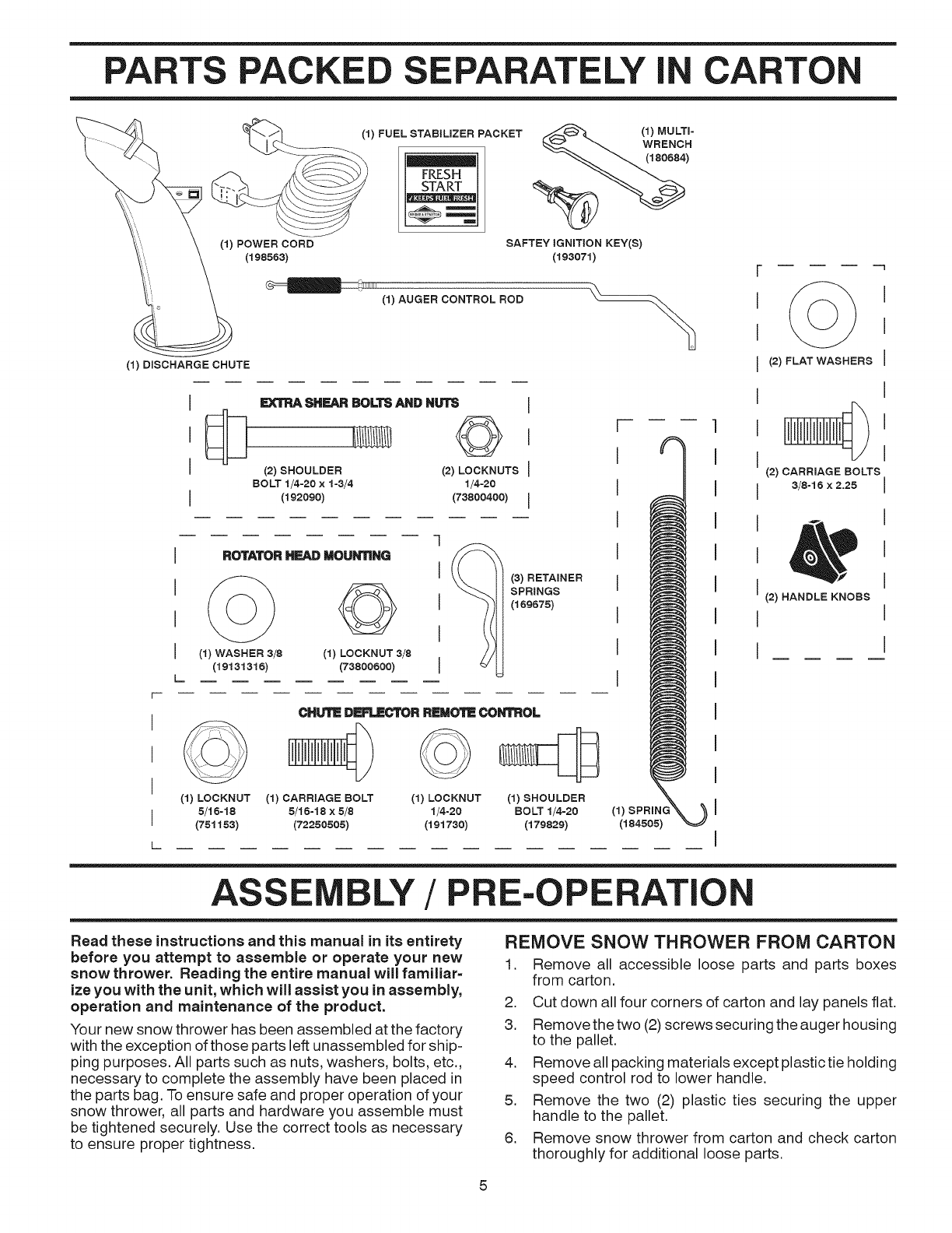
PARTS PACKE E ELY ICARTON
(1) POWER CORD
(198883)
(1) FUEL STABILIZER PACKET
FRESH
_._ 1) MULTI-
WRENCH
(188884)
SAFTEY IGNITION KEY(S)
(193071)
1111111
(1) AUGER CONTROL ROD
(1) DISCHARGE CHUTE
I
I
SHEARBOLTSANDNUTS
©
(2) SHOULDER (2) LOCKNUTS
BOLT 1/4-20 × 1-3/4 1/4=20
(192090) (73800400)
ROTATORHEAD MOUNTING
I(1) WASHER 3/8 (1) LOCKNUT 3/8
(19131316) (73800600)
[
q
I
I
I
I
(3) RETAINER
SPRINGS
(189878)
CHUTE DERLBCTORREMOTE CONTROL
(1) LOCKNUT (1) CARRIAGE BOLT (1) LOCKNUT
5/16-18 5/16-18 x5/8 1/4-20 (1) k %
(751153) (72250505) (191730) (184505)
(1) SHOULDER
BOLT 1/4-20
(179829)
(2) FLAT WASHERS
(2) CARRIAGE BOLTS
3/8-16 x2.25
(2) HANDLE KNOBS
ASS LY /PE-OPERATIC
Read these instructions and this manual in its entirety
before you attempt to assemble or operate your new
snow thrower. Reading the entire manual will familiar=
ize you with the unit, which will assist you in assembly,
operation and maintenance of the product.
Your new snow thrower has been assembled at the factory
with the exception of those parts left unassembled for ship-
ping purposes. All parts such as nuts, washers, bolts, etc.,
necessary to complete the assembly have been placed in
the parts bag. To ensure safe and proper operation of your
snow thrower, all parts and hardware you assemble must
be tightened securely. Use the correct tools as necessary
to ensure proper tightness.
REMOVE SNOW THROWER FROM CARTON
1. Remove all accessible loose parts and parts boxes
from carton.
2. Cut down all four corners of carton and lay panels flat.
3. Remove the two (2)screws securing the auger housing
to the pallet.
4. Remove all packing materials except plastic tie holding
speed control rod to lower handle.
5. Remove the two (2) plastic ties securing the upper
handle to the pallet.
6. Remove snow thrower from carton and check carton
thoroughly for additional loose parts.
ASSE BLY/PRE-OPERATION
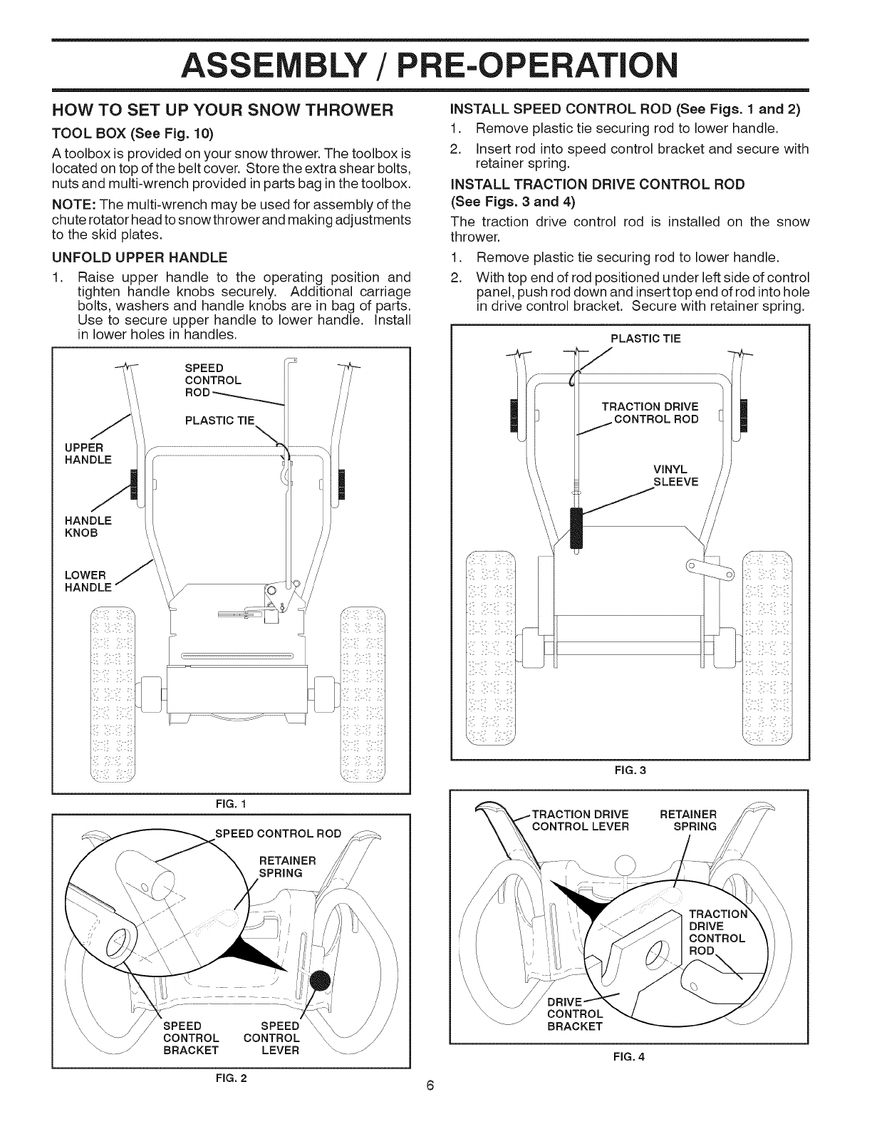
HOW TO SET UP YOUR SNOW THROWER
TOOL BOX (See Fig. 10)
A toolbox is provided on your snow thrower. The toolbox is
located on top of the belt cover. Store the extra shear bolts,
nuts and multi-wrench provided in parts bag inthe toolbox.
NOTE: The multi-wrench may be used for assembly of the
chute rotator head to snow thrower and making adjustments
to the skid plates.
UNFOLD UPPER HANDLE
.Raise upper handle to the operating position and
tighten handle knobs securely. Additional carriage
bolts, washers and handle knobs are in bag of parts.
Use to secure upper handle to lower handle. Install
in lower holes in handles.
SPEED
CONTROL
UPPER
HANDLE
PLASTIC TIE
HANDLE
KNOB
LOWER
HANDLE f
I I
iNSTALL SPEED CONTROL ROD (See Figs. 1 and 2)
1. Remove plastic tie securing rod to lower handle.
2. Insert rod into speed control bracket and secure with
retainer spring.
iNSTALL TRACTION DRIVE CONTROL ROD
(See Figs. 3 and 4)
The traction drive control rod is installed on the snow
thrower.
1. Remove plastic tie securing rod to lower handle.
2. With top end of rod positioned under left side of control
panel, push rod down and inserttop end of rod into hole
in drive control bracket. Secure with retainer spring.
PLASTIC TIE
TRACTION DRIVE
CONTROLROD
VINYL
SLEEVE
FIG. 3
FIG. 1
SPEED CONTROL ROD
RETAINER
SPRING
SPEED
CONTROL
BRACKET
SPEED
CONTROL
LEVER
DRIVE RETAINER
SPRING
CONTROL
BRACKET
FIG. 4
FIG. 2 6
ASS LY /PE-OPERATIC
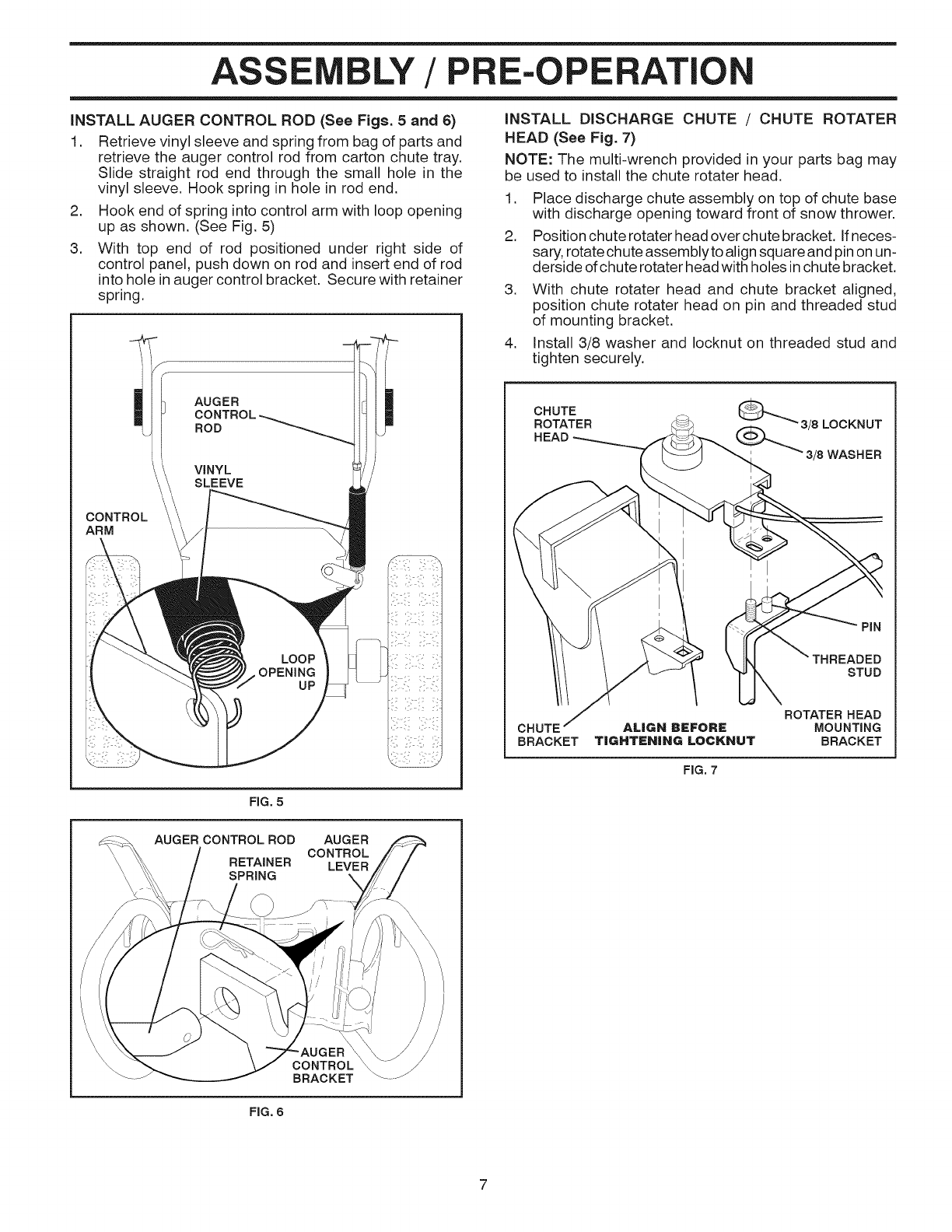
iNSTALL AUGER CONTROL ROD (See Figs. 5and 6)
1. Retrieve vinyl sleeve and spring from bag of parts and
retrieve the auger control rod from carton chute tray.
Slide straight rod end through the small hole in the
vinyl sleeve. Hook spring in hole in rod end.
2. Hook end of spring into control arm with loop opening
up as shown. (See Fig. 5)
3. With top end of rod positioned under right side of
control panel, push down on rod and insert end of rod
into hole inauger control bracket. Secure with retainer
spring.
CONTROL
ARM
AUGER
iNSTALL DISCHARGE CHUTE /CHUTE ROTATER
HEAD (See Fig. 7)
NOTE: The multi-wrench provided in your parts bag may
be used to install the chute rotater head.
1. Place discharge chute assembly on top of chute base
with discharge opening toward front of snow thrower.
2. Position chute rotater head over chute bracket. If neces-
sary, rotate chute assemblyto align square and pin on un-
derside of chute rotater head with holes in chute bracket.
3. With chute rotater head and chute bracket aligned,
position chute rotater head on pin and threaded stud
of mounting bracket.
4. Install 3/8 washer and Iocknut on threaded stud and
tighten securely.
CHUTE
ROTATER
HEAD
_3/8LOCKNUT
_3/8 WASHER
PIN
STUD
ROTATER HEAD
MOUNTING
BRACKET
FIG. 7
FIG. 5
AUGER CONTROL ROD AUGER
CONTROL
RETAINER LEVER
SPRING X
CONTROL
BRACKET
FIG. 6
ASSE BLY/PRE-OPERATION
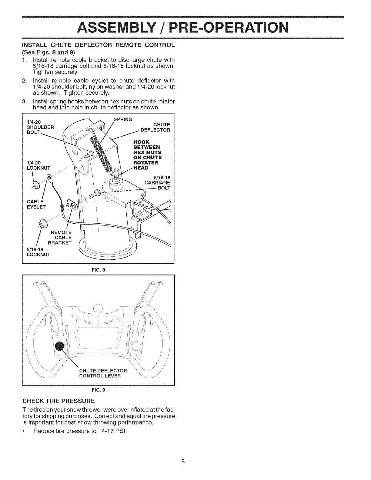
iNSTALL CHUTE DEFLECTOR REMOTE CONTROL
(See Figs. 8 and 9)
1. Install remote cable bracket to discharge chute with
5/16-18 carriage bolt and 5/16-18 Iocknut as shown.
Tighten securely.
2. Install remote cable eyelet to chute deflector with
1/4-20 shoulder bolt, nylon washer and 1/4-20 Iocknut
as shown. Tighten securely.
3. Install spring hooks between hex nuts on chute rotater
head and into hole in chute deflector as shown.
1/4-20 SPRING
SHOULDER CHUTE
1/4-2o
LOCKNUT /"
CABLE
EYELET
/J
REMOTE
/ CABLE
/BRACKET
5/16-18
LOCKNUT
FIG, 8
CHUTE DEFLECTOR
CONTROLLEVER
FIG, 9
CHECK TiRE PRESSURE
The tires on your snow thrower were overinflated at the fac-
tory for shipping purposes. Correct and equal tire pressure
is important for best snow throwing performance.
• Reduce tire pressure to 14-17 PSI.
8
PE
KNOW YOUR SNOW THROWER
READ THIS OWNER'S MANUALAND ALL SAFETY RULES BEFORE OPERATING YOUR SNOWTHROWER. Compare
the illustrations with your snow thrower to familiarize yourself with the location of various controls and adjustments. Save
this manual for future reference.
These symbols may appear on your snow thrower or in literature supplied with the product. Learn and understand
their meaning.
DANGER ENGINE ENGINE FAST
OR WARNING ON OFF
I\1
SLOW CHOKE PRIMER
FUEL OIL FORWARD REVERSE
READ AND FOLLOW ALL SAFETY iNFORMATiON
AND iNSTRUCTiONS BEFORE USE OF THIS PRODUCT.
KEEP THESE INSTRUCTIONS FOR FUTURE REFERENCE.
IGNITION KEY.
INSERT TO START
AND RUN,
PULL OUT TO STOP.
DISENGAGED
ENGAGED
SNOW
DISCHARGE
TRACTION
DRIVE CONTROL
OPERATI
T
GASOLINE AUGER DRIVE DISCHARGE
FILLER CAP CONTROL SPEED CHUTE
ELECTRIC LEVER CONTROL CONTROL
LEVER LEVER
MUFFLER START
BUTTON
RECOIL
,(AUXiLiARY)
CHOKE STARTER
CONTROL HANDLE CHUTE
DEFLECTOR
OFF
SWITCH
DEFLECTOR
REMOTE
CONTROL
LEVER
TRACTION
DRaVE
CONTROL
LEVER
PRIMER
SAFETY
iGNiTiON
KEY
LH TURN
TRIGGER
THROTTLE DISCHARGE
CHUTE
CLEAN=OUT
TOOL
NOTE:ITEMS ABOVE
ARE SHOWNIN
THEIR TYPICAL
LOCATION ON THE
ENGINE, ACTUAL
LOCATION MAY
VARY WiTH THE
ENGINE ONYOUR
UNI_
\
MEETS A.N.SJ. SAFETY AUGERS
REQUIREMENTS
Our snow throwers conform to the standards of
the American National Standards institute.
Toolbox -used to store spare shear bolts, Iocknuts and
wrench.
Safety ignition key = must be inserted for the engine to
start and run. Remove when snow thrower is not in use.
Electric start button -used for starting the engine.
Recoil (auxiliary) starter handle -used for starting the
engine.
Drive speed control lever = used to select forward or
reverse motion and speed of snow thrower.
Primer = pumps additional fuel from the carburetor to the
cylinder for use when starting a cold engine.
Throttle/engine control - used to select either FAST or
SLOW engine speed and to STOP the engine.
ON /OFF switch - used to STOP the engine.
FIG. 10
10
HANDLE
KNOB
MUFFLER
TOOLBOX
DRIFT
CUTTER
PLATE
Choke control =used for starting a cold engine.
Traction drive control lever = used to engage power-
propelled forward or reverse motion of snow thrower.
Auger control lever -used to engage auger motion (throw
snow).
Deflector remote control lever =used to change the di-
stance the snow is thrown.
Discharge chute control lever =used to change the direc-
tion the snow is thrown.
LH and RH turn triggers =used to steer the snow thrower.
Skid plate =used to adjust height of scraper bar from the
ground.
Drift cutter =used to cut through deep snowdrifts.
PE
The operation of any snow thrower can result
in foreign objects thrown into the eyes, which
can result insevere eye damage. Always wear
safety glasses or eye shields while operating
your snow thrower or performing any adjust-
ments or repairs. We recommend standard safety glasses
or a wide vision safety mask worn over spectacles.
HOW TO USE YOUR SNOW THROWER
Know how to operate all controls before adding fuel or
attempting to start the engine.
STOPPING
TRACTION DRIVE
• Release traction drive control lever to stop the forward
or reverse movement of the snow thrower.
AUGER
• Release the auger control lever to stop throwing snow.
ENGINE
1. Move ON /OFF switch to "OFF" position.
2. Remove (do not turn) safety ignition key to prevent
unauthorized use.
NOTE: Never use choke to stop engine.
TO USE THROTTLE CONTROL (See Fig. 11)
The throttle control is located on the engine. Always operate
the snow thrower with the engine at full throttle. Full throttle
offers the best snow thrower performance.
FAST
FIG. 11
TO USE CHOKE CONTROL (See Fig. 12)
The choke control is located on the engine. Use the choke
control whenever you are starting a cold engine. Do not
use to start a warm engine.
• To engage choke, turn knob clockwise. Slowly turn
knob counterclockwise to disengage.
FIG. 12
TO CONTROL SNOW DISCHARGE (See Fig. 13)
&WARNING: Snow throwers have ex=
posed rotating parts, which can cause
severe injury from contact, or from ma-
terial thrown from the discharge chute.
Keep the area of operation clear of all
persons, small children and pets at all
times including startup.
WARNING: If the discharge chute or
auger become clogged, shut=off engine
and wait for all moving parts to stop. Use
the clean=out tool, NOT YOUR HANDS,
to unclo the chute and/or au er.
The DIRECTION inwhich snow isto be thrown is controlled
by the discharge chute control lever.
• Tochange the discharge chute position, press downward
on discharge chute control lever and move lever left
or right until chute is in desired position. Be sure lever
springs back and locks into desired position.
The DISTANCE that snow is thrown is controlled by the
position of the chute deflector. Set the deflector low to
throw snow a short distance; set the deflector higher to
throw snow farther.
Press downward on chute deflector control lever and
move lever forward to lower the deflector and decrease
the distance. Move lever back to raise the deflector
and increase the distance. Be sure lever springs back
and locks into desired position.
DISCHARGECHUTE
CONTROLLEVER
FIG. 13
TO THROW SNOW (See Fig. 14)
The auger rotation is controlled by the auger control lever
located on the right side handle.
• Squeeze auger control lever to handle to engage the
auger and throw snow.
• Release the auger control lever to stop throwing snow.
AUGER
LEVER
11 FIG.14
OPERATION
USING THE CLEAN=OUT TOOL (See Fig. 15)
In certain snow conditions, the discharge chute may be-
come clogged with ice and snow. Use the clean-out tool
to dislodge this blockage.
When cleaning, repairing, or inspecting, make
certain all controls are disengaged and the au=
get/impeller and all moving parts have stopped.
Disconnect the spark plug wire and keep the
wire away from the spark plug to prevent ac=
cidental starting.
• Release the auger control lever and shut offthe engine.
• Remove the clean-out tool from it'smounting clip. Grasp
the tool firmly by the handle and push and twist the tool
into the discharge chute to dislodge the blockage.
After the packed snow has been dislodged, return the clean-
out tool to it's mounting clip by pushing it into the clip.
• Make sure the discharge chute is pointed inasafe direc-
tion (no vehicles, buildings, people, or other objects are
inthe direction of discharge) before restarting the engine.
• Restart the engine, then squeeze the auger control
lever to the handle to clear snow from the auger hous-
ing and the discharge chute.
• Slower speeds are for heavier snow and faster speeds
are for light snow and transporting the snow thrower. It
is recommended that you use a slower speed until you
are familiar with the operation of the snow thrower.
NOTE: When both traction drive and auger control levers
are engaged, the traction drive control lever will lock the
auger control lever inthe engaged position. This will allow
you to release your right hand from the handle and adjust
the discharge chute direction without interrupting the snow
throwing process.
TRACTION DRIVE
LEVER
DRaVE SPEED
CONTROL LEVER
CLEAN-OUT'
TOOL
FIG. 15
TO MOVE FORWARD AND BACKWARD (See Fig. 16)
SELF-PROPELLING, forward and reverse movement of
the snow thrower, is controlled by the traction drive control
lever located on the left side handle.
• Squeeze traction drive control lever to handle to engage
the drive system.
• Release traction drive control lever to stop the forward
or reverse movement of the snow thrower.
SPEED and DIRECTION are controlled by the drive speed
control lever.
Press downward on the speed control lever and move
lever to desired position BEFORE engaging the trac-
tion drive control lever. Be sure lever springs back and
locks into desired position.
CAUTION: Do not move speed control lever
when traction drive control lever is engaged.
Damage to the snow thrower can result.
FIG. 16
POWER STEERING OPERATION (See Fig. 17)
Steering triggers are used to assist in steering your
snow thrower. The triggers are located on the underside
of each handle. When a trigger is squeezed, it disen-
gages the drive wheel on that side of snow thrower and
allows it to turn in that direction.
• To turn left - squeeze left side trigger.
• To turn right - squeeze right side trigger.
LH TURN RH TURN
TRIGGER TRIGGER
FIG. 17
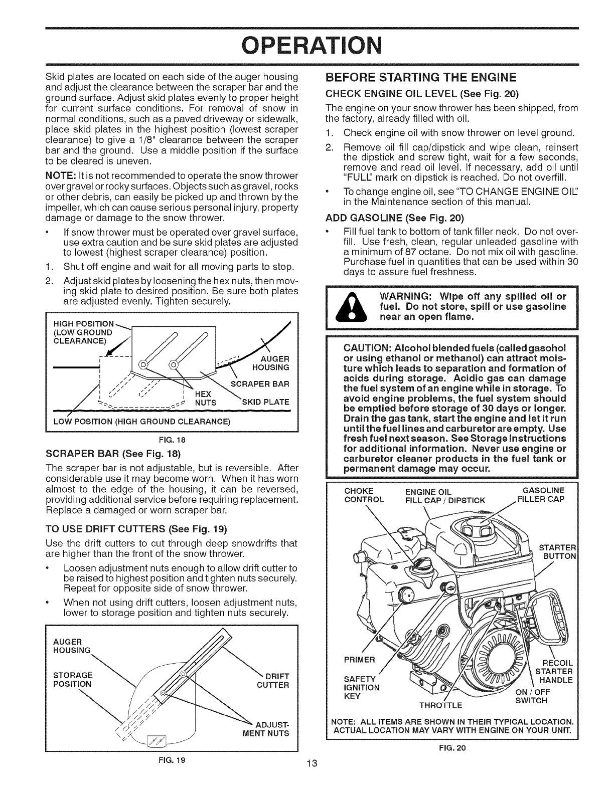
TO ADJUST SKiD PLATES (See Fig. 18)
NOTE: The wrench provided in your parts bag may be
used to adjust the skid plates.
12
OPERATION
Skid plates are located on each side of the auger housing
and adjust the clearance between the scraper bar and the
ground surface. Adjust skid plates evenly to proper height
for current surface conditions. For removal of snow in
normal conditions, such as a paved driveway or sidewalk,
place skid plates in the highest position (lowest scraper
clearance) to give a 1/8" clearance between the scraper
bar and the ground. Use a middle position if the surface
to be cleared is uneven.
NOTE: It is not recommended to operate the snow thrower
over gravel or rocky surfaces. Objects such as gravel, rocks
or other debris, can easily be picked up and thrown by the
impeller, which can cause serious personal injury, property
damage or damage to the snow thrower.
• If snow thrower must be operated over gravel surface,
use extra caution and be sure skid plates are adjusted
to lowest (highest scraper clearance) position.
1. Shut off engine and wait for all moving parts to stop.
2. Adjustskid plates by loosening the hex nuts, then mov-
ing skid plate to desired position. Be sure both plates
are adjusted evenly. Tighten securely.
HiGH
(LOW GROUND
_)
AUGER
II HOUSING
4
', / SCRAPER BAR
.--.. == NUTS_ "_'._,KI ) '1. _.TI"
/
LOW POSITION (HIGH GROUND CLEARANCE)
FIG. 18
SCRAPER BAR (See Fig. 18)
The scraper bar is not adjustable, but is reversible. After
considerable use it may become worn. When it has worn
almost to the edge of the housing, it can be reversed,
providing additional service before requiring replacement.
Replace a damaged or worn scraper bar.
TO USE DRIFT CUTTERS (See Fig. 19)
Use the drift cutters to cut through deep snowdrifts that
are higher than the front of the snow thrower.
• Loosen adjustment nuts enough to allow drift cutter to
be raised to highest position and tighten nuts securely.
Repeat for opposite side of snow thrower.
• When not using drift cutters, loosen adjustment nuts,
lower to storage position and tighten nuts securely.
AUGER
HOUSING
STORAGE DRIFT
POSITION CUTTER
/ /. ADJUST-
\ MENT NUTS
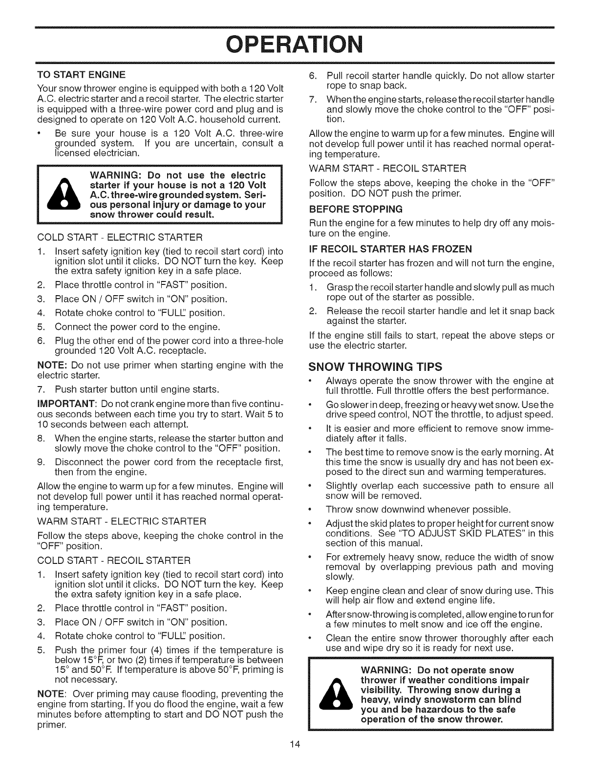
BEFORE STARTING THE ENGINE
CHECK ENGINE OIL LEVEL (See Fig. 20)
The engine on your snow thrower has been shipped, from
the factory, already filled with oil.
1. Check engine oil with snow thrower on level ground.
2. Remove oil fill cap/dipstick and wipe clean, reinsert
the dipstick and screw tight, wait for a few seconds,
remove and read oil level. If necessary, add oil until
"FULl" mark on dipstick is reached. Do not overfill.
• To change engine oil, see "TO CHANGE ENGINE OIL'
in the Maintenance section of this manual.
ADD GASOLINE (See Fig. 20)
• Fill fuel tank to bottom of tank filler neck. Do not over-
fill. Use fresh, clean, regular unleaded gasoline with
a minimum of 87 octane. Do not mix oil with gasoline.
Purchase fuel in quantities that can be used within 30
days to assure fuel freshness.
WARNING: Wipe off any spilled oil or
fuel. Do not store, spill or use gasoline
near an open flame.
CAUTION: Alcohol blended fuels (called gasohol
or using ethanol or methanol) can attract tools=
ture which leads to separation and formation of
acids during storage. Acidic gas can damage
the fuel system of an engine while in storage. To
avoid engine problems, the fuel system should
be emptied before storage of 30 days or longer.
Drain the gas tank, start the engine and let it run
until the fuel lines and carburetor are empty. Use
fresh fuel next season. See Storage Instructions
for additional information. Never use engine or
carburetor cleaner products in the fuel tank or
permanent damage may occur.
CHOKE ENGINE OIL GASOLINE
CONTROL FILL CAP /DIPSTICK FILLER CAP
STARTER
BUTTON
PRIMER RECOIL
STARTER
SAFETY HANDLE
IGNITION ON/OFF
KEY SWITCH
THROTTLE
NOTE: ALL ITEMS ARE SHOWN IN THEIR TYPICAL LOCATION.
ACTUAL LOCATION MAY VARY WiTH ENGINE ON YOUR UNIT.
FIG. 20
FIG. 19 13
OPERATION
TO START ENGINE
Your snow thrower engine is equipped with both a 120 Volt
A.C. electric starter and a recoil starter. The electric starter
is equipped with a three-wire power cord and plug and is
designed to operate on 120 Volt A.C. household current.
• Be sure your house is a 120 Volt A.C. three-wire
grounded system. If you are uncertain, consult a
licensed electrician.
&WARNING: Do not use the electric
starter if your house is not a120 Volt
A.C. three-wire grounded system. Seri=
ous personal injury or damage to your
snow thrower could result.
COLD START - ELECTRIC STARTER
1. Insert safety ignition key (tied to recoil start cord) into
ignition slot until it clicks. DO NOT turn the key. Keep
the extra safety ignition key in a safe place.
2. Place throttle control in "FAST" position.
3. Place ON /OFF switch in "ON" position.
4. Rotate choke control to "FULl" position.
5. Connect the power cord to the engine.
6. Plug the other end of the power cord into a three-hole
grounded 120 Volt A.C. receptacle.
NOTE: Do not use primer when starting engine with the
electric starter.
7. Push starter button until engine starts.
iMPORTANT: Do not crank engine more than five continu-
ous seconds between each time you try to start. Wait 5 to
10 seconds between each attempt.
8. When the engine starts, release the starter button and
slowly move the choke control to the "OFF" position.
9. Disconnect the power cord from the receptacle first,
then from the engine.
Allow the engine to warm up for a few minutes. Engine will
not develop full power until it has reached normal operat-
ing temperature.
WARM START - ELECTRIC STARTER
Follow the steps above, keeping the choke control in the
"OFF" position.
COLD START - RECOIL STARTER
1. Insert safety ignition key (tied to recoil start cord) into
ignition slot until it clicks. DO NOT turn the key. Keep
the extra safety ignition key in a safe place.
2. Place throttle control in "FAST" position.
3. Place ON /OFF switch in "ON" position.
4. Rotate choke control to "FULl" position.
5. Push the primer four (4) times if the temperature is
below 15°F, or two (2) times if temperature is between
15° and 50°R If temperature is above 50°F, priming is
not necessary.
NOTE: Over priming may cause flooding, preventing the
engine from starting. If you do flood the engine, wait a few
minutes before attempting to start and DO NOT push the
primer.
6. Pull recoil starter handle quickly. Do not allow starter
rope to snap back.
7. When the engine starts, release the recoil starter handle
and slowly move the choke control to the "OFF" posi-
tion.
Allow the engine to warm up for a few minutes. Engine will
not develop full power until it has reached normal operat-
ing temperature.
WARM START- RECOIL STARTER
Follow the steps above, keeping the choke in the "OFF"
position. DO NOT push the primer.
BEFORE STOPPING
Run the engine for a few minutes to help dry off any mois-
ture on the engine.
iF RECOIL STARTER HAS FROZEN
If the recoil starter has frozen and will not turn the engine,
proceed as follows:
1. Grasp the recoil starter handle and slowly pull as much
rope out of the starter as possible.
2. Release the recoil starter handle and let it snap back
against the starter.
If the engine still fails to start, repeat the above steps or
use the electric starter.
SNOW THROWING TiPS
• Always operate the snow thrower with the engine at
full throttle. Full throttle offers the best performance.
• Go slower indeep, freezing or heavy wet snow. Use the
drive speed control, NOT the throttle, to adjust speed.
• It is easier and more efficient to remove snow imme-
diately after it falls.
• The best time to remove snow is the early morning. At
this time the snow is usually dry and has not been ex-
posed to the direct sun and warming temperatures.
• Slightly overlap each successive path to ensure all
snow will be removed.
e
e
Throw snow downwind whenever possible.
Adjust the skid plates to proper height for current snow
conditions. See "TO ADJUST SKID PLATES" in this
section of this manual.
• For extremely heavy snow, reduce the width of snow
removal by overlapping previous path and moving
slowly.
• Keep engine clean and clear of snow during use. This
will help air flow and extend engine life.
• After snow-throwing is completed, allow engine to runfor
a few minutes to melt snow and ice off the engine.
• Clean the entire snow thrower thoroughly after each
use and wipe dry so it is ready for next use.
&WARNING: Do not operate snow
thrower if weather conditions impair
visibility. Throwing snow during a
heavy, windy snowstorm can blind
you and be hazardous to the safe
operation of the snow thrower.
14
E A CE
MAINTENANCE
FILL IN DATES
AS YOU COMPLETE
REGULAR SERVICE
Check for Loose Fasteners
RClean/Inspect Snow Thrower
O
WCheck /Replace V=Belts
RE Lubrication Chart
v' v'
v' V
V
v' v'
Check Engine Oil Level
E
N Change Engine Oil
Inspect Muffler
N Check /Replace Spark Plug
EEmpty Fuel Tank
V
v'
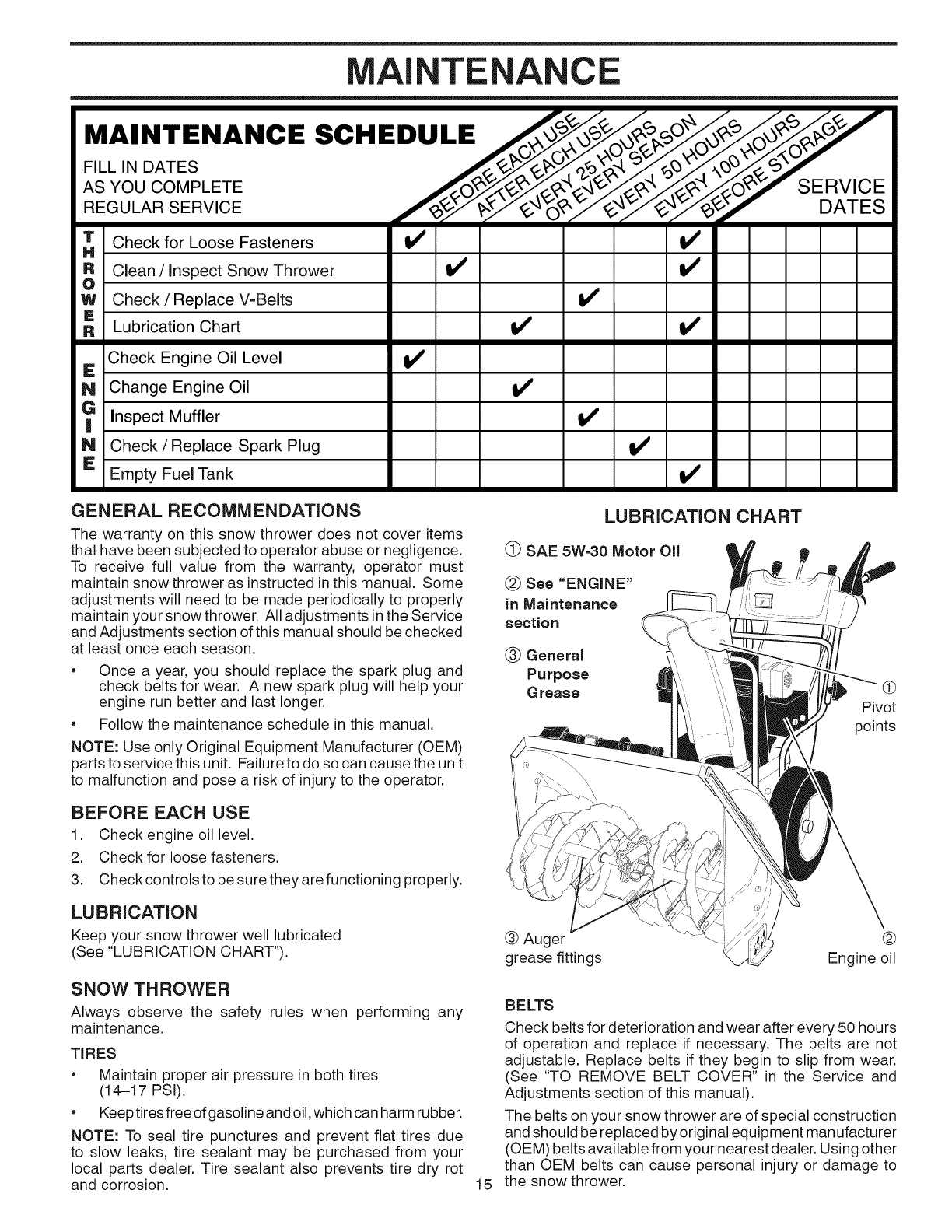
GENERAL RECOMMENDATIONS
The warranty on this snow thrower does not cover items
that have been subjected to operator abuse or negligence.
To receive full value from the warranty, operator must
maintain snow thrower as instructed in this manual. Some
adjustments will need to be made periodically to properly
maintain your snow thrower. All adjustments in the Service
and Adjustments section of this manual should be checked
at least once each season.
•Once a year, you should replace the spark plug and
check belts for wear. A new spark plug will help your
engine run better and last longer.
•Follow the maintenance schedule in this manual.
NOTE: Use only Original Equipment Manufacturer (OEM)
parts to service this unit. Failure to do so can cause the unit
to malfunction and pose a risk of injury to the operator.
LUBRiCATiON CHART
(_ SAE 5W=30 Motor Oil
(_) See "ENGINE"
in Maintenance
section
(_) General
Purpose
Grease Pivot
points
BEFORE EACH USE
1. Check engine oil level.
2. Check for loose fasteners.
3. Check controls to be sure they are functioning properly.
LUBRiCATiON
Keep your snow thrower well lubricated
(See "LUBRICATION CHART"). ® Auger @
grease fittings Engine oil
SNOW THROWER
Always observe the safety rules when performing any
maintenance.
TIRES
•Maintain proper air pressure in both tires
(14-17 PSI).
•Keep tires free of gasoline and oil, which can harm rubber.
NOTE: To seal tire punctures and prevent flat tires due
to slow leaks, tire sealant may be purchased from your
local parts dealer. Tire sealant also prevents tire dry rot
and corrosion. 15
BELTS
Check belts for deterioration and wear after every 50 hours
of operation and replace if necessary. The belts are not
adjustable. Replace belts if they begin to slip from wear.
(See "TO REMOVE BELT COVER" in the Service and
Adjustments section of this manual).
The belts on your snow thrower are of special construction
and should be replaced by original equipment manufacturer
(OEM) belts available from your nearest dealer. Using other
than OEM belts can cause personal injury or damage to
the snow thrower.
NTE A CE
AUGER GEAR CASE
The gear case was filled with lubricant to the proper
level at the factory. The only time the lubricant needs
attention is if service has been performed on the gear
case.
•If lubricant is required, use only Ronex ED #1
grease.
TRACTION DRIVE SYSTEM
DO NOT lubricate the drive components inside the snow
thrower. The sprockets, hex shafts, drive disc and friction
wheel require no lubrication. The bearings and bushings
are lifetime lubricated and require no maintenance.
CAUTION: Any lubricating of the above compo=
nents can cause contamination of the friction
wheel and damage to the drive system of your
snow thrower.
ENGINE
See engine manual.
LUBRICATION
Use only high quality detergent oil rated with API service
classification SG-SL. Select the oil's SAE viscosity grade
according to your expected operating temperature.
SAE VISCOSITY GRADES
I I
i°F -20 0 30 32 40
°c -30 -2'o -1'0 6 lo
TEMPERATURE RANGE ANTICIPATED
BEFORE NEXT OIL CHANGE
NOTE: Although multi-viscosity oils (5W30, 10W30 etc.)
improve starting in cold weather, these multi-viscosity oils
will result in increased oil consumption when used above
32°R Check your engine oil level more frequently to avoid
possible engine damage from running low on oil.
Changethe oilafter every25 hours of operation orat leastonce
ayear if the snow thrower is not used for 25 hours inone year.
Check the crankcase oil level before starting the engine and
after each five (5) hours of continuous use. Tighten oil fill
cap /dipstick securely each time you check the oil level.
TO CHANGE ENGINE OIL
Determine temperature range anticipated before next oil
change. All oil must meet API service classification SG-SL.
•Be sure snow thrower is on level surface.
•Oil will drain more freely when warm.
•Catch oil in a suitable container.
NOTE: The left side wheel may be removed from snow
thrower for easier access to the oil drain plug and place-
ment of a suitable container. The unit tilted, resting on the
frame with the left wheel removed, will help drain any oil
trapped inside the engine. (See "TO REMOVE WHEELS"
in the Service and Adjustments section of this manual).
1. Remove safety ignitionkey and disconnect spark plug
wire from spark plug. Place wire where it cannot come
in contact with spark plug.
2. Clean area around drain plug.
3. Remove drain plug and drain oil in a suitable container.
4. Install drain plug and tighten securely.
5. Wipe off any spilled oil from snow thrower and engine.
6. Install left wheel (if removed for draining oil). Besureto
install klick pin into proper hole in wheel axle (See "TO
REMOVE WHEELS" in the Service and Adjustments
section of this manual).
7. Remove oil fill cap/dipstick. Be careful not to allow dirt
to enter the engine.
8. Refill engine with oil through oil dipstick tube. Pour
slowly. Do not overfill. For approximate capacity see
"PRODUCT SPECIFICATIONS" section of this manual.
9. Use gauge on oil fill cap/dipstick for checking level.
Be sure dipstick cap is tightened securely for accurate
reading. Keep oil at "FULE' line on dipstick.
10. Wipe off any spilled oil.
MUFFLER
Inspect and replace corroded muffler as it could create a
fire hazard and/or damage.
SPARK PLUG
Replace spark plug at the beginning of each season or after
every 100 hours of operation, whichever occurs first. Spark
plug type and gap setting are shown in the "PRODUCT
SPECIFICATIONS" section of this manual.
CLEANING
IMPORTANT: For best performance, keep snow thrower
housing free of any dirt or trash. Clean the outside of your
snow thrower after each use.
&WARNING: Remove safety ignition key
and disconnect spark plug wire from
spark plug. Place wire where it cannot
come in contact with spark plug.
e
e
Keep finished surfaces/wheels free of gasoline, oil, etc.
We do not recommend using a garden hose to clean
your snow thrower unless the electrical system, muffler
and carburetor are covered to keep water out. Water
in engine can result in shortened engine life.
16
SE ADJ ENTS
WARNING: To avoid serious injury, before performing any service or adjustments:
1. Be sure the on/off switch is in the OFF position.
2. Remove safety ignition key.. Make sure the augers and all moving parts have completely stopped.
4. Disconnect spark plug wire from spark plug and place wire where it cannot come in contact
with plug.
SNOW THROWER
TO ADJUST SNOW THROWER HEIGHT
See "TO ADJUST SKID PLATES" and "SCRAPER BAR"
in the Operation section of this manual.
CHUTE DEFLECTOR
The chute deflector, attached to the top of the discharge
chute, is provided to direct discharging snow away from
the operator. If the deflector becomes damaged, it should
be replaced.
WARNING: To avoid serious injury,
never operate your snow thrower with
the deflector removed or damaged.
• Tochange direction and!or distance snow isdischarged,
see "TO CONTROL SNOW DISCHARGE" in the Op-
eration section of this manual.
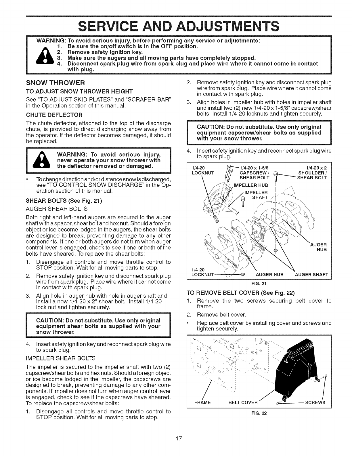
SHEAR BOLTS (See Fig. 21)
AUGER SHEAR BOLTS
Both right and left-hand augers are secured to the auger
shaft with a spacer, shear bolt and hex nut. Should a foreign
object or ice become lodged in the augers, the shear bolts
are designed to break, preventing damage to any other
components. If one or both augers do not turn when auger
control lever is engaged, check to see if one or both of the
bolts have sheared. To replace the shear bolts:
1. Disengage all controls and move throttle control to
STOP position. Wait for all moving parts to stop.
2. Remove safety ignition key and disconnect spark plug
wire from spark plug. Place wire where itcannot come
in contact with spark plug.
3. Align hole in auger hub with hole in auger shaft and
install a new 1/4-20 x 2" shear bolt. Install 1/4-20
lock nut and tighten securely.
CAUTION: Do not substitute. Use only original
equipment shear bolts as supplied with your
snow thrower.
2. Remove safety ignition key and disconnect spark plug
wire from spark plug. Place wire where it cannot come
in contact with spark plug.
3. Align holes in impeller hub with holes in impeller shaft
and installtwo (2) new 1/4-20 x 1-5/8" capscrew/shear
bolts. Install 1/4-20 Iocknuts and tighten securely.
CAUTION: Do not substitute. Use only original
equipment capscrew/shear bolts as supplied
with your snow thrower.
4. Insert safety ignitionkey and reconnect spark plug wire
to spark plug.
1/4-20 1/4-20 x 2
LOCKNUT CAPSCREW /_SHOULDER /
SHEAR BOLT "_ --'"_ SHEAR BOLT
IMPELLER HUB
HUB
1/4-20 _.-z AUGER HUB AUGER SHAFT
FIG, 21
TO REMOVE BELT COVER (See Fig. 22)
1. Remove the two screws securing belt cover to
frame.
2. Remove belt cover.
• Replace belt cover by installing cover and screws and
tighten securely.
4. Insert safety ignitionkey and reconnect spark plug wire
to spark plug.
IMPELLER SHEAR BOLTS
The impeller is secured to the impeller shaft with two (2)
capscrew/shear bolts and hex nuts. Should aforeign object
or ice become lodged in the impeller, the capscrews are
designed to break, preventing damage to any other com-
ponents. If impeller does not turn when auger control lever
is engaged, check to see if the capscrews have sheared.
To replace the capscrew/shear bolts:
1. Disengage all controls and move throttle control to
STOP position. Wait for all moving parts to stop.
FRAME BELT COVER
FIG. 22
SCREWS
17
SE ADJ
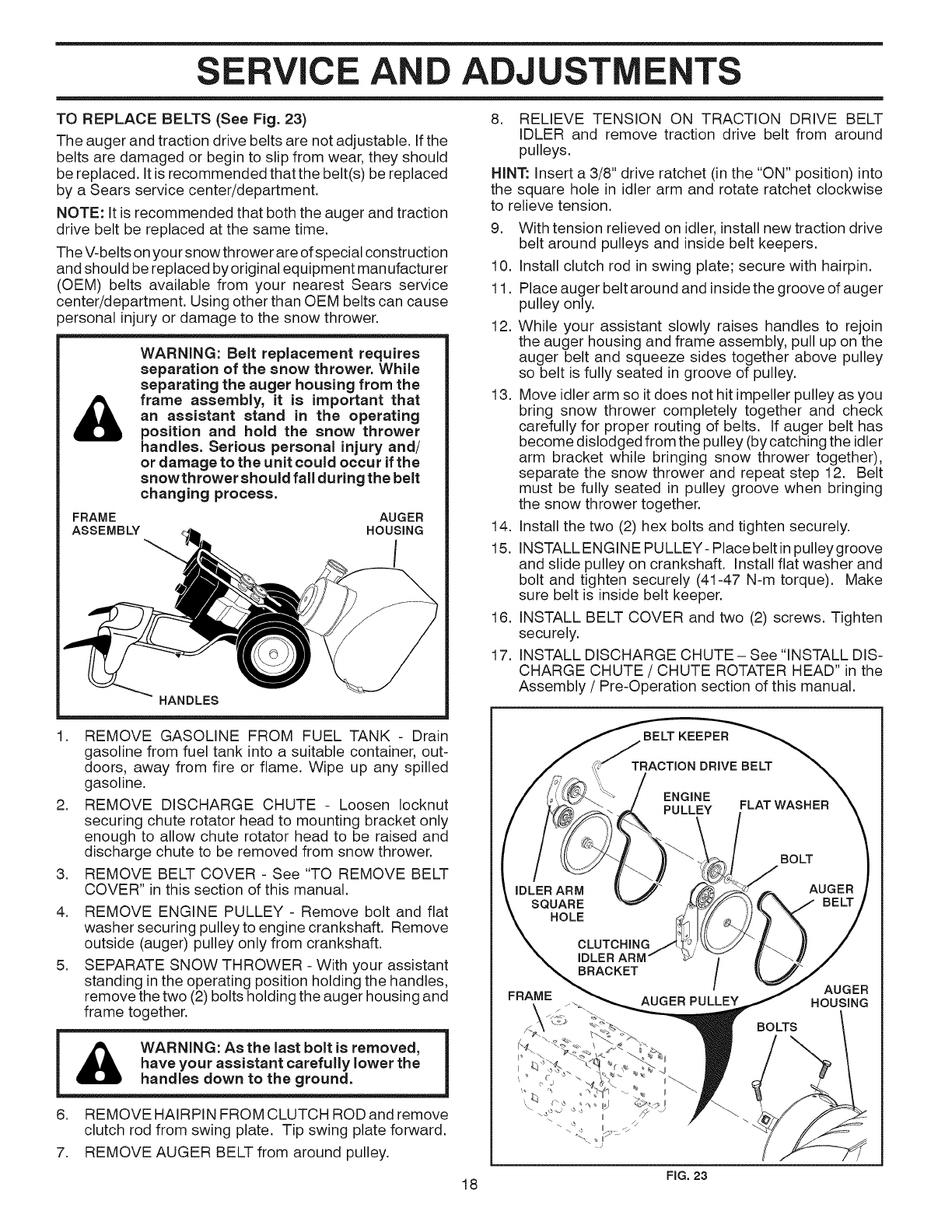
TO REPLACE BELTS (See Fig. 23)
The auger and traction drive belts are not adjustable. If the
belts are damaged or begin to slip from wear, they should
be replaced. It is recommended that the belt(s) be replaced
by a Sears service center/department.
NOTE: It is recommended that both the auger and traction
drive belt be replaced at the same time.
The V-belts on your snow thrower are of special construction
and should be replaced by original equipment manufacturer
(OEM) belts available from your nearest Sears service
center/department. Using other than OEM belts can cause
)ersonal injury or damage to the snow thrower.
&
WARNING: Belt replacement requires
separation of the snow thrower. While
separating the auger housing from the
frame assembly, it is important that
an assistant stand in the operating
position and hold the snow thrower
handles. Serious personal injury and/
or damage to the unit could occur if the
snowthrower should fall during the belt
changing process.
FRAME
ASSEMBLY AUGER
HOUSING
HANDLES
8. RELIEVE TENSION ON TRACTION DRIVE BELT
IDLER and remove traction drive belt from around
pulleys.
HINT: Insert a 3/8" drive ratchet (in the "ON" position) into
the square hole in idler arm and rotate ratchet clockwise
to relieve tension.
9. With tension relieved on idler, install new traction drive
belt around pulleys and inside belt keepers.
10. Install clutch rod in swing plate; secure with hairpin.
11. Place auger belt around and inside the groove of auger
pulley only.
12. While your assistant slowly raises handles to rejoin
the auger housing and frame assembly, pull up on the
auger belt and squeeze sides together above pulley
so belt is fully seated in groove of pulley.
13. Move idler arm so it does not hit impeller pulley as you
bring snow thrower completely together and check
carefully for proper routing of belts. If auger belt has
become dislodged from the pulley (by catching the idler
arm bracket while bringing snow thrower together),
separate the snow thrower and repeat step 12. Belt
must be fully seated in pulley groove when bringing
the snow thrower together.
14. Install the two (2) hex bolts and tighten securely.
15. INSTALL ENGINE PULLEY- Place belt inpulley groove
and slide pulley on crankshaft. Install flat washer and
bolt and tighten securely (41-47 N-m torque). Make
sure belt is inside belt keeper.
16. INSTALL BELT COVER and two (2) screws. Tighten
securely.
17. INSTALL DISCHARGE CHUTE- See "INSTALL DIS-
CHARGE CHUTE /CHUTE ROTATER HEAD" in the
Assembly /Pre-Operation section of this manual.
.
.
.
4.
5.
REMOVE GASOLINE FROM FUEL TANK - Drain
gasoline from fuel tank into a suitable container, out-
doors, away from fire or flame. Wipe up any spilled
gasoline.
REMOVE DISCHARGE CHUTE - Loosen Iocknut
securing chute rotator head to mounting bracket only
enough to allow chute rotator head to be raised and
discharge chute to be removed from snow thrower.
REMOVE BELT COVER - See "TO REMOVE BELT
COVER" in this section of this manual.
REMOVE ENGINE PULLEY - Remove bolt and flat
washer securing pulley to engine crankshaft. Remove
outside (auger) pulley only from crankshaft.
SEPARATE SNOW THROWER - With your assistant
standing inthe operating position holding the handles,
remove the two (2) bolts holding the auger housing and
frame together.
WARNING: As the last bolt is removed,
have your assistant carefully lower the
handles down to the ground.
6. REMOVE HAIRPIN FROM CLUTCH ROD and remove
clutch rod from swing plate. Tip swing plate forward.
7. REMOVE AUGER BELT from around pulley.
BELT KEEPER
TRACTION DRIVE BELT
ENGINE
PULLEY FLAT WASHER
IDLER ARM
SQUARE
HOLE
BRACKET /
AUGER PULLEY
FRAME
II
BOLT
AUGER
BELT
AUGER
HOUSING
BOLTS
18 FIG.23
SE iCE ADJ ENTS
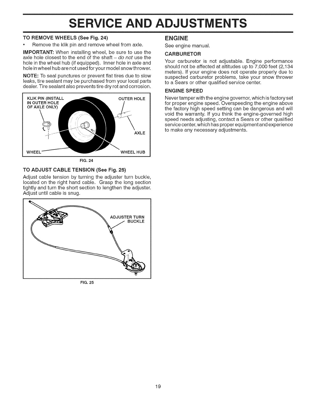
TO REMOVE WHEELS (See Fig. 24)
• Remove the klik pin and remove wheel from axle.
IMPORTANT: When installing wheel, be sure to use the
axle hole closest to the end of the shaft - do not use the
hole in the wheel hub (if equipped), inner hole in axle and
hole inwheel hub are not used for your model snow thrower.
NOTE: To seal punctures or prevent flat tires due to slow
leaks, tire sealant may be purchased from your local parts
dealer. Tire sealant also prevents tire dry rot and corrosion.
KLIK PiN (iNSTALL
iN OUTER HOLE
OF AXLE ONLY)
OUTERHOLE
AXLE
WHEEL WHEEL HUB
ENGINE
See engine manual.
CARBURETOR
Your carburetor is not adjustable. Engine performance
should not be affected at altitudes up to 7,000 feet (2,134
meters). If your engine does not operate properly due to
suspected carburetor problems, take your snow thrower
to a Sears or other qualified service center.
ENGINE SPEED
Never tamper with the engine governor, which is factory set
for proper engine speed. Overspeeding the engine above
the factory high speed setting can be dangerous and will
void the warranty, if you think the engine-governed high
speed needs adjusting, contact a Sears or other qualified
service center, which has proper equipment and experience
to make any necessary adjustments.
FIG. 24
TO ADJUST CABLE TENSION (See Fig. 25)
Adjust cable tension by turning the adjuster turn buckle,
located on the right hand cable. Grasp the long section
tightly and turn the short section to lengthen the adjuster.
Adjust until cable is snug.
ADJUSTER TURN
BUCKLE
FIG, 25
19
STORAGE
Immediately prepare your unit for storage at the end of the
season or if the unit will not be used for 30 days or more.
&
WARNING: Never store the snow
thrower with gasoline in the tank inside
a building where fumes may reach an
open flame, spark or pilot light as on a
furnace, water heater, clothes dryer or
gas appliance. AIIowthe engine to cool
before storing in any enclosure.
SNOW THROWER
When snow thrower is to be stored for a period of time,
clean it thoroughly, remove all dirt, grease, leaves, etc.
Store in a clean, dry area.
1. Clean entire snow thrower (See "CLEANING" in the
Maintenance section of this manual).
2. Inspect and replace belts, if necessary (See "TO RE-
PLACE BELTS" inthe Service and Adjustments section
of this manual).
Lubricate as shown inthe Maintenance section of this
manual.
.
4.
5.
Be sure that all nuts, bolts, screws, and pins are securely
fastened. Inspect moving parts for damage, breakage
and wear. Replace if necessary.
Touch up all rusted or chipped paint surfaces; sand
lightly before painting.
ENGINE
See engine manual.
FUEL SYSTEM
IMPORTANT: It is important to prevent gum deposits from
forming in essential fuel system parts such as carburetor,
fuel hose, or tank during storage. Also, alcohol blended
fuels (called gasohol or using ethanol or methanol) can
attract moisture which leads to separation and formation
of acids during storage. Acidic gas can damage the fuel
system of an engine while in storage.
• Empty the fuel tank by starting the engine and letting
it run until the fuel lines and carburetor are empty.
• Never use engine or carburetor cleaner products in
the fuel tank or permanent damage may occur.
• Use fresh fuel next season.
NOTE: Fuel stabilizer is an acceptable alternative in mini-
mizing the formation of fuel gum deposits during storage.
Add stabilizer to gasoline in fuel tank or storage container.
Always follow the mix ratio found on stabilizer container.
Run engine at least 10 minutes after adding stabilizer to
allow the stabilizer to reach the carburetor. Do not drain the
gas tank and carburetor if using fuel stabilizer.
ENGINE OIL
Drain oil (with engine warm) and replace with clean engine
oil. (See "ENGINE" in the Maintenance section of this
manual).
CYLINDER
1. Remove spark plug.
2. Pour one ounce (29 ml) of oil through spark plug hole
into cylinder.
3. Pull recoil starter handle slowly a few times to distribute
oil.
4. Replace with new spark plug.
OTHER
• Remove safety ignition key; store it in a safe place.
• Do not store gasoline from one season to another.
• Replace your gasoline can if your can starts to rust.
Rust and/or dirt in your gasoline will cause problems.
• If possible, store your snow thrower indoors and cover
it to protect it from dust and dirt.
•Cover your snow thrower with a suitable protective
cover that does not retain moisture. Do not use plastic.
Plastic cannot breathe, which allows condensation to
form and will cause your snow thrower to rust.
IMPORTANT: Never cover snow thrower while engine/ex-
haust area is still warm.
20
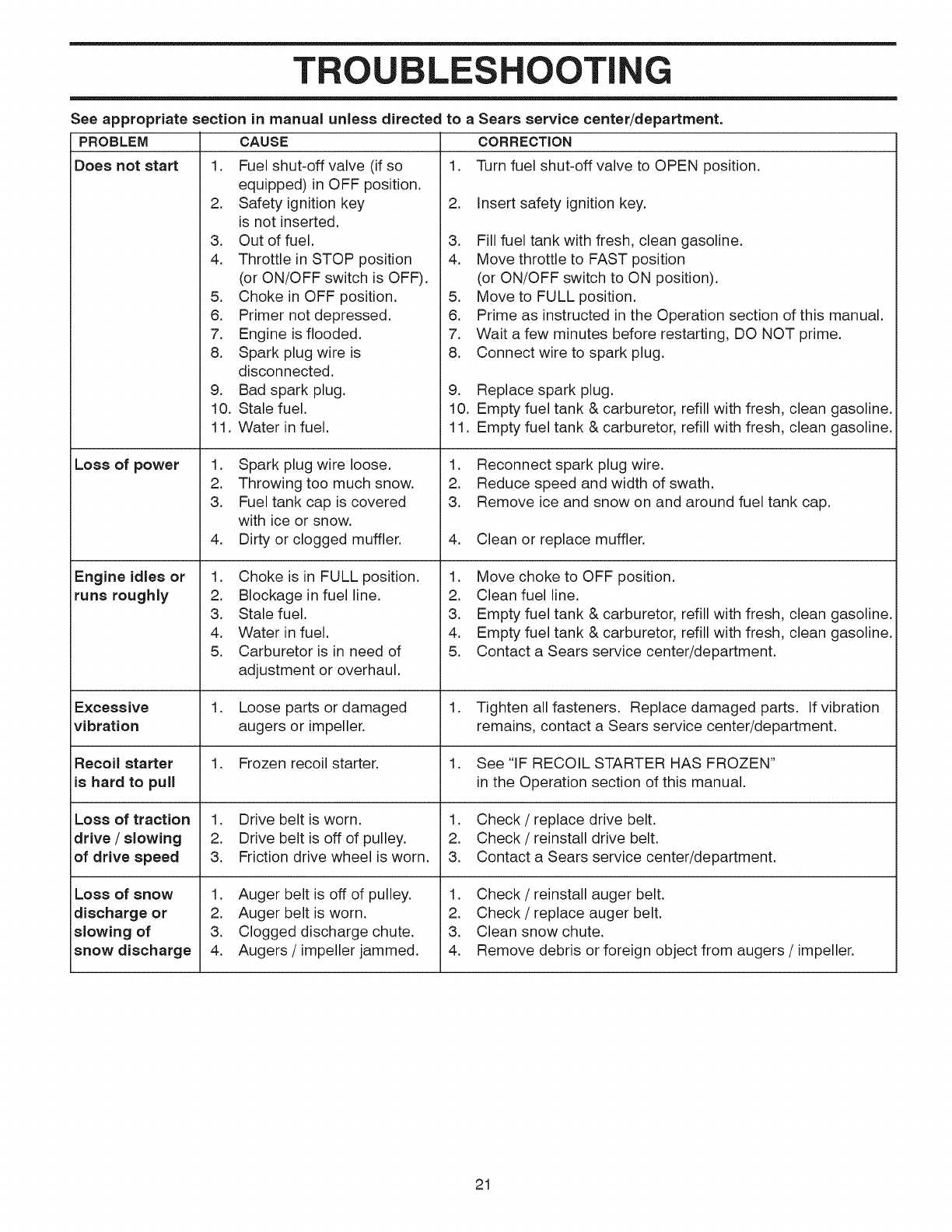
TR LOTI
See appropriate section in manual unless directed
PROBLEM CAUSE
Does not start 1.
Loss of power
Engine idles or
runs roughly
Excessive
vibration
Recoil starter
is hard to pull
Loss of traction
drive /slowing
of drive speed
Loss of snow
discharge or
slowing of
snow discharge
Fuel shut-off valve (if so
equipped) in OFF position.
2. Safety ignition key
is not inserted.
3. Out of fuel.
4. Throttle in STOP position
(or ON/OFF switch is OFF).
5. Choke in OFF position.
6. Primer not depressed.
7. Engine is flooded.
8. Spark plug wire is
disconnected.
9. Bad spark plug.
10. Stale fuel.
11. Water in fuel.
1. Spark plug wire loose.
2. Throwing too much snow.
3. Fuel tank cap is covered
with ice or snow.
4. Dirty or clogged muffler.
1. Choke is in FULL position.
2. Blockage in fuel line.
3. Stale fuel.
4. Water in fuel.
5. Carburetor is in need of
adjustment or overhaul.
.Loose parts or damaged
augers or impeller.
1. Frozen recoil starter.
1. Drive belt is worn.
2. Drive belt is off of pulley.
3. Friction drive wheel is worn.
1. Auger belt is off of pulley.
2. Auger belt is worn.
3. Clogged discharge chute.
4. Augers /impeller jammed.
to a Sears service center/department.
CORRECTION
1. Turn fuel shut-off valve to OPEN position.
2. Insert safety ignition key.
3. Fill fuel tank with fresh, clean gasoline.
4. Move throttle to FAST position
(or ON/OFF switch to ON position).
5. Move to FULL position.
6. Prime as instructed in the Operation section of this manual.
7. Wait a few minutes before restarting, DO NOT prime.
8. Connect wire to spark plug.
9. Replace spark plug.
10. Empty fuel tank & carburetor, refill with fresh, clean gasoline.
11. Empty fuel tank & carburetor, refill with fresh, clean gasoline.
1. Reconnect spark plug wire.
2. Reduce speed and width of swath.
3. Remove ice and snow on and around fuel tank cap.
4. Clean or replace muffler.
1. Move choke to OFF position.
2. Clean fuel line.
3. Empty fuel tank & carburetor, refill with fresh, clean gasoline.
4. Empty fuel tank & carburetor, refill with fresh, clean gasoline.
5. Contact a Sears service center/department.
1. Tighten all fasteners. Replace damaged parts. If vibration
remains, contact a Sears service center/department.
1. See "IF RECOIL STARTER HAS FROZEN"
in the Operation section of this manual.
1. Check /replace drive belt.
2. Check /reinstall drive belt.
3. Contact a Sears service center/department.
1. Check /reinstall auger belt.
2. Check /replace auger belt.
3. Clean snow chute.
4. Remove debris or foreign object from augers /impeller.
21
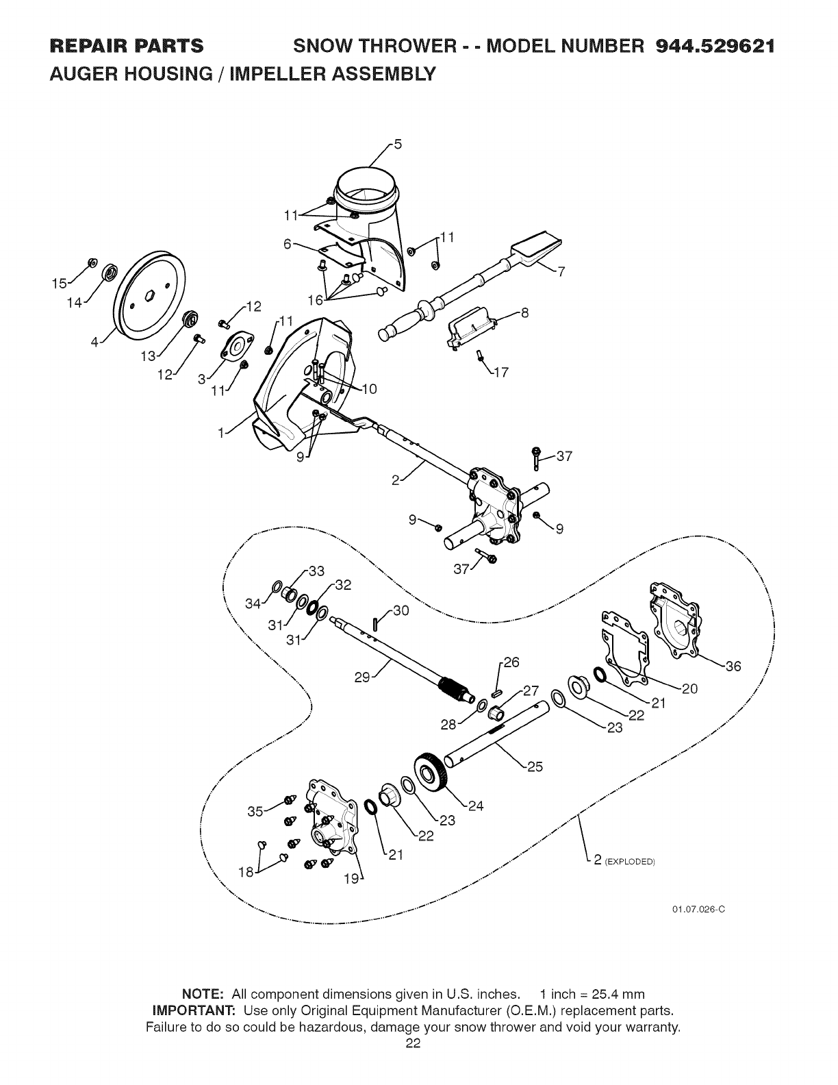
REPAIR PARTS SNOW THROWER - - MODEL NUMBER 944,529621
AUGER HOUSING /iMPELLER ASSEMBLY
5
11
6 11
\17
NOTE: All component dimensions given in U.S. inches. 1 inch = 25.4 mm
iMPORTANT: Use only Original Equipment Manufacturer (O.E.M.) replacement parts.
Failure to do so could be hazardous, damage your snow thrower and void your warranty.
22
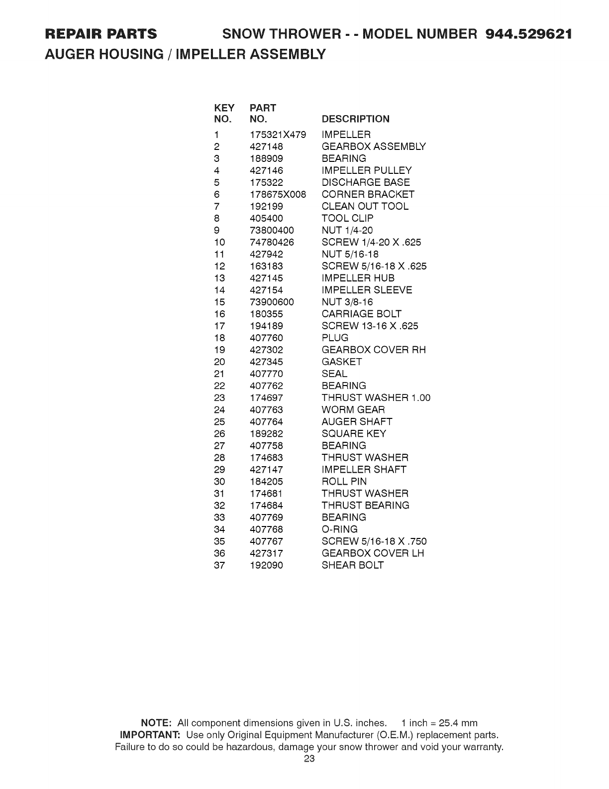
REPAIR PARTS SNOW THROWER - - MODEL NUMBER 944,529621
AUGER HOUSING /iMPELLER ASSEMBLY
KEY PART
NO. NO. DESCRiPTiON
1 175321X479 IMPELLER
2 427148 GEARBOX ASSEMBLY
3 188909 BEARING
4 427146 IMPELLER PULLEY
5 175322 DISCHARGE BASE
6 178675X008 CORNER BRACKET
7 192199 CLEAN OUT TOOL
8 405400 TOOL CLIP
9 73800400 NUT 1/4-20
10 74780426 SCREW 1/4-20 X .625
11 427942 NUT 5/16-18
12 163183 SCREW 5/16-18 X .625
13 427145 IMPELLER HUB
14 427154 IMPELLER SLEEVE
15 73900600 NUT 3/8-16
16 180355 CARRIAGE BOLT
17 194189 SCREW 13-16 X .625
18 407760 PLUG
19 427302 GEARBOX COVER RH
20 427345 GASKET
21 407770 SEAL
22 407762 BEARING
23 174697 THRUST WASHER 1.00
24 407763 WORM GEAR
25 407764 AUGER SHAFT
26 189282 SQUARE KEY
27 407758 BEARING
28 174683 THRUST WASHER
29 427147 IMPELLER SHAFT
30 184205 ROLL PIN
31 174681 THRUST WASHER
32 174684 THRUST BEARING
33 407769 BEARING
34 407768 O-RING
35 407767 SCREW 5/16-18 X .750
36 427317 GEARBOX COVER LH
37 192090 SHEAR BOLT
NOTE: All component dimensions given in U.S. inches. 1 inch = 25.4 mm
iMPORTANT: Use only Original Equipment Manufacturer (O.E.M.) replacement parts.
Failure to do so could be hazardous, damage your snow thrower and void your warranty.
23
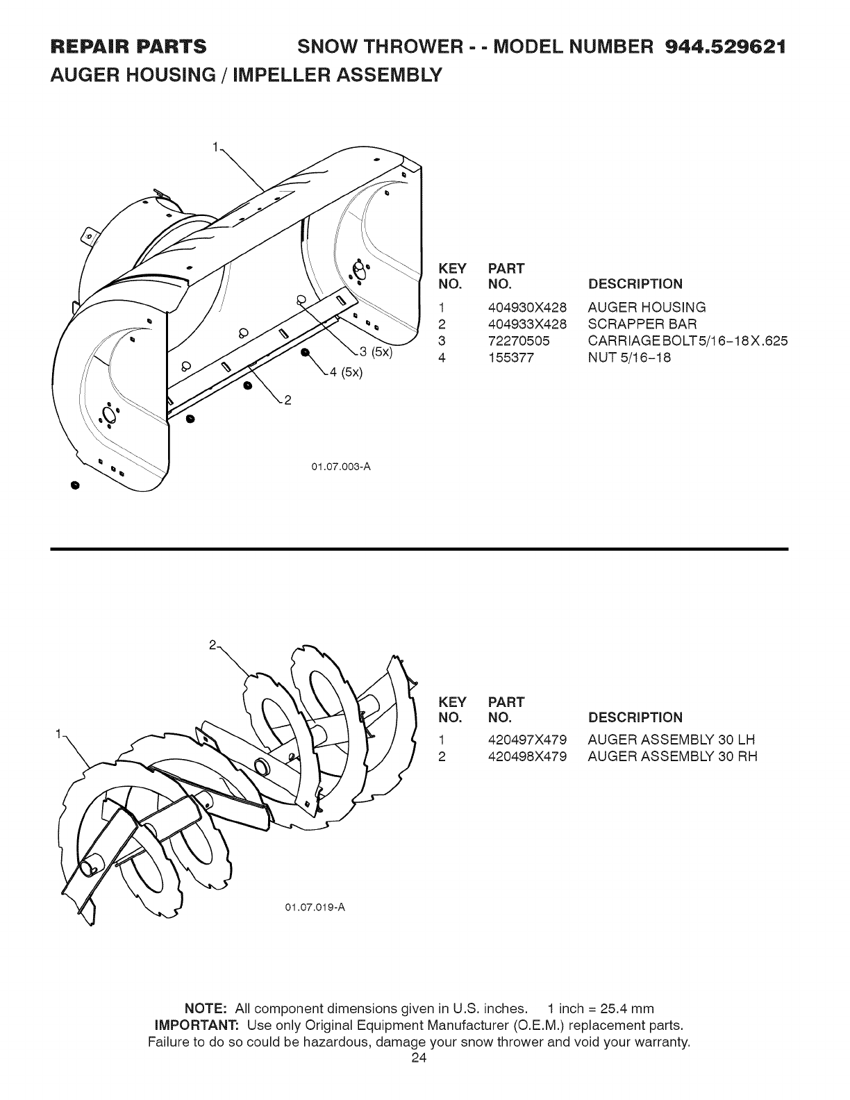
REPAIR PARTS SNOW THROWER - - MODEL NUMBER 944,529621
AUGER HOUSING /iMPELLER ASSEMBLY
_(5x)
(5x)
KEY PART
NO. NO. DESCRIPTION
1
2
3
4
404930X428
404933X428
72270505
155377
AUGERHOUSING
SCRAPPER BAR
CARRIAGEBO_5/16-18X.625
NUT5/16-18
01.07.003-A
2
1
KEY PART
NO. NO.
1 420497X479
2 420498X479
DESCRIPTION
AUGER ASSEMBLY 30 LH
AUGER ASSEMBLY 30 RH
NOTE: All component dimensions given in U.S. inches. 1 inch = 25.4 mm
iMPORTANT: Use only Original Equipment Manufacturer (O.E.M.) replacement parts.
Failure to do so could be hazardous, damage your snow thrower and void your warranty.
24
REPAIR PARTS SNOW THROWER - - MODEL NUMBER 944,529621
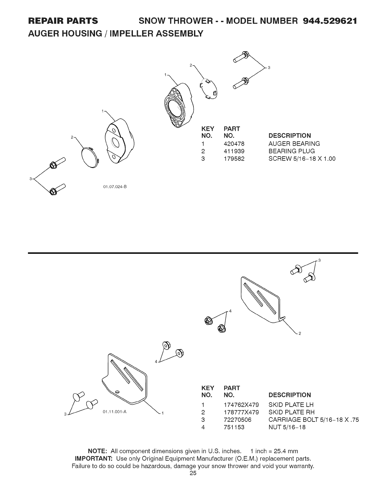
AUGER HOUSING /iMPELLER ASSEMBLY
01.07.024-B
2
1 \
KEY
NO.
1
2
3
PART
NO.
420478
411939
179582
DESCRIPTION
AUGER BEARING
BEARING PLUG
SCREW 5/16-18 X 1.00
01.11.001-A
KEY PART
NO. NO. DESCRIPTION
1 174762X479 SKID PLATE LH
2 178777X479 SKID PLATE RH
3 72270506 CARRIAGE BOLT 5/16-18 X .75
4 751153 NUT 5/16-18
NOTE: All component dimensions given in U.S. inches. 1inch = 25.4 mm
IMPORTANT: Use only Original Equipment Manufacturer (O.E.M.) replacement parts.
Failure to do so could be hazardous, damage your snow thrower and void your warranty.
25
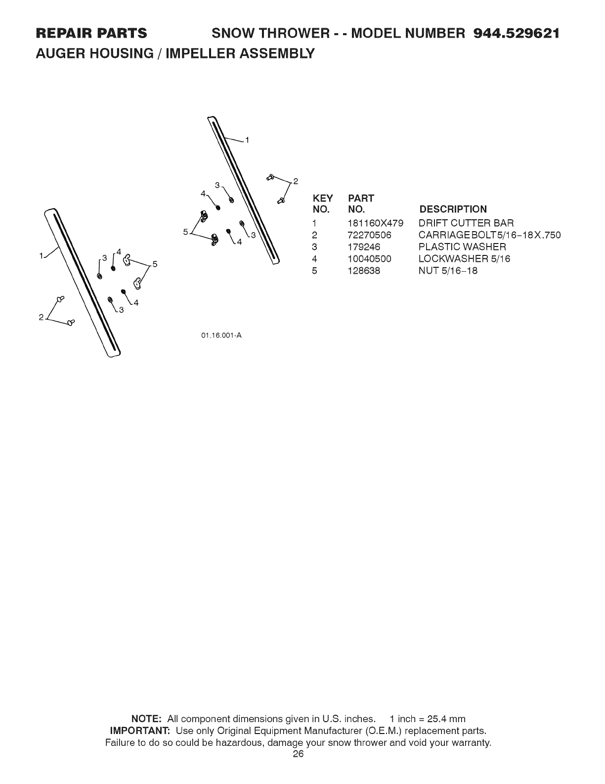
REPAIR PARTS SNOW THROWER - - MODEL NUMBER 944,529621
AUGER HOUSING /iMPELLER ASSEMBLY
3KEY PART
4\_ NO. NO.
1 181160X479
2 72270506
5 .._ qtk._ 3 179246
4 10040500
5 128638
01.16.001-A
DESCRIPTION
DRIFT CUTTER BAR
CARR IAGE BOLT 5/16-18 X .750
PLASTIC WASHER
LOCKWASHER 5/16
N UT 5/16-18
NOTE: All component dimensions given in U.S. inches. 1 inch = 25.4 mm
iMPORTANT: Use only Original Equipment Manufacturer (O.E.M.) replacement parts.
Failure to do so could be hazardous, damage your snow thrower and void your warranty.
26
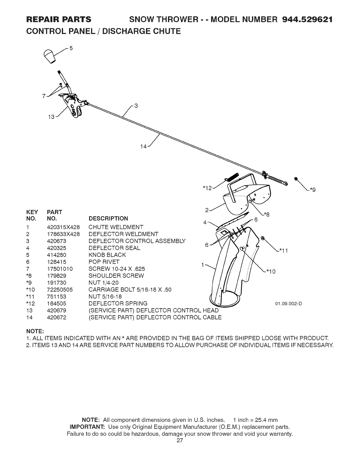
REPAIR PARTS SNOW THROWER - - MODEL NUMBER
CONTROL PANEL /DISCHARGE CHUTE
944,529621
13
14
KEY PART
NO. NO.
1 420315X428
2 178833X428
3 420873
4 420325
5 414280
8 128415
7 17501010
*8 179829
*9 191730
"10 72250505
"11 751153
"12 184505
13 420879
14 420872
DESCRIPTION
CHUTE WELDMENT
DEFLECTOR WELDMENT
DEFLECTOR CONTROL ASSEMBLY
DEFLECTOR SEAL
KNOB BLACK
POP RIVET 1
SCREW 10-24 X .625
SHOULDER SCREW
NUT 1/4-20
CARRIAGE BOLT 5/16-18 X .50
N UT 5/16-18
DEFLECTOR SPRING
(SERVICE PART) DEFLECTOR CONTROL HEAD
(SERVICE PART) DEFLECTOR CONTROL CABLE
11
01,09,002-D
NOTE:
1. ALL ITEMS INDICATED WITH AN * ARE PROVIDED IN THE BAG OF ITEMS SHIPPED LOOSE WITH PRODUCT.
2. ITEMS 13 AND 14 ARE SERVICE PART NUMBERS TO ALLOW PURCHASE OF INDIVIDUAL ITEMS IF NECESSARY.
NOTE: All component dimensions given in U.S. inches. 1inch = 25.4 mm
IMPORTANT: Use only Original Equipment Manufacturer (O.E.M.) replacement parts.
Failure to do so could be hazardous, damage your snow thrower and void your warranty.
27
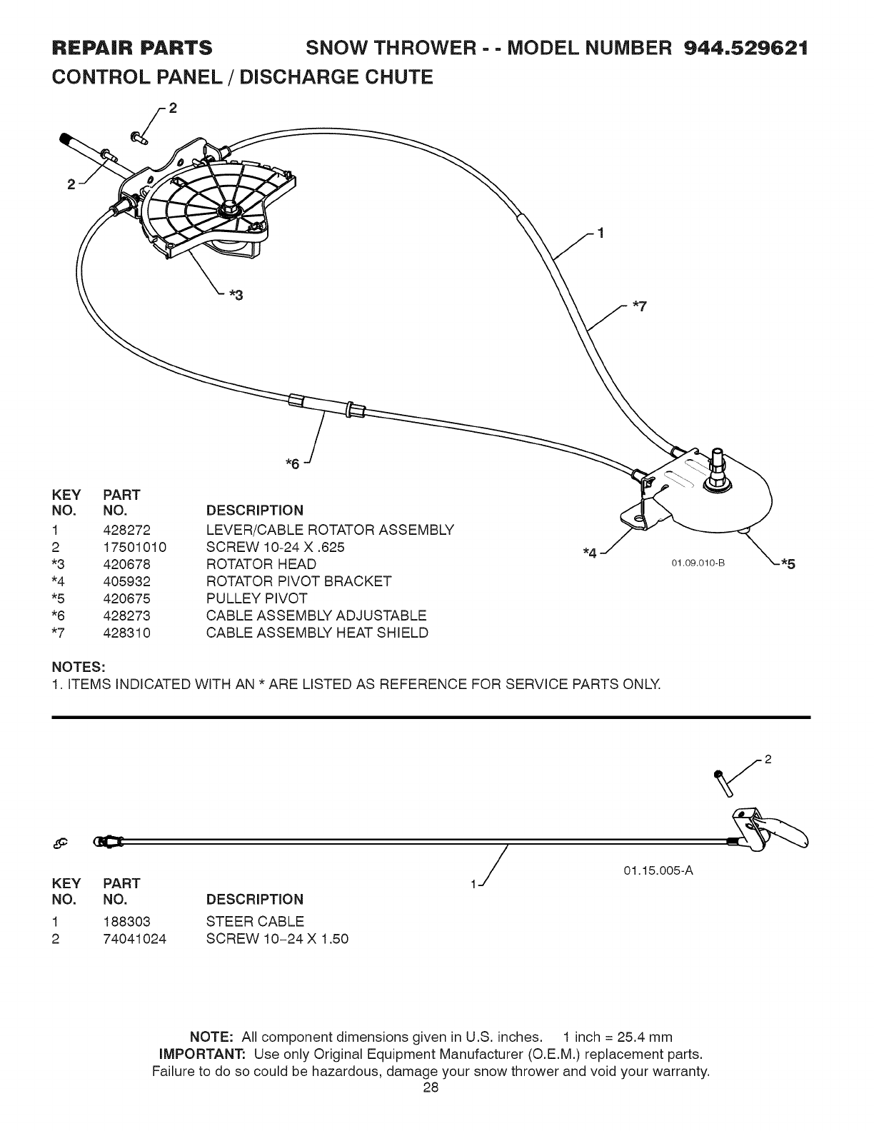
REPAIR PARTS SNOW THROWER - - MODEL NUMBER
CONTROL PANEL /DISCHARGE CHUTE
944,529621
KEY PART
NO. NO.
1 428272
2 17501010
*3 420678
*4 405932
*5 420675
*6 428273
*7 428310
DESCRIPTION
LEVER/CABLE ROTATOR ASSEMBLY
SCREW 10-24 X .625
ROTATOR HEAD
ROTATOR PIVOT BRACKET
PULLEY PIVOT
CABLE ASSEMBLY ADJUSTABLE
CABLE ASSEMBLY HEAT SHIELD
NOTES:
1. ITEMS INDICATED WITH AN * ARE LISTED AS REFERENCE FOR SERVICE PARTS ONLY.
01.09.010-B
KEY PART
NO. NO. DESCRIPTION
1 188303 STEER CABLE
2 74041024 SCREW 10-24 X 1.50
1/ 01.15.005-A
NOTE: All component dimensions given in U.S. inches. 1 inch = 25.4 mm
iMPORTANT: Use only Original Equipment Manufacturer (O.E.M.) replacement parts.
Failure to do so could be hazardous, damage your snow thrower and void your warranty.
28
REPAIR PARTS
HANDLES
SNOW THROWER - - MODEL NUMBER 944,529621
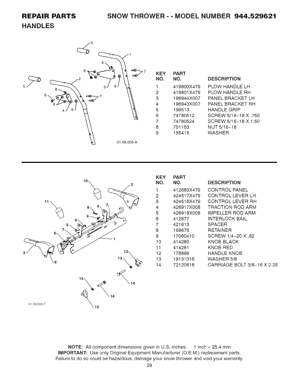
(_5 _ 1
KEY PART
NO. NO. DESCRIPTION
1 419800X479 PLOW HANDLE LH
2 419801X479 PLOW HANDLE RH
3 196944X007 PANEL BRACKET LH
4 196943X007 PANEL BRACKET RH
5 199513 HANDLE GRIP
6 74780512 SCREW 5/16-18 X .750
7 74780524 SCREW 5/16-18 X 1.50
8 751153 NUT 5/16-18
9 155415 WASHER
01.08.002-F
14
KEY PART
NO. NO. DESCRIPTION
1 412683X479 CONTROL PANEL
2 424517X479 CONTROL LEVER LH
3 424516X479 CONTROL LEVER RH
4 426917X008 TRACTION ROD ARM
5 426918X008 IMPELLER ROD ARM
6 412677 INTERLOCK BAIL
7 421613 SPACER
8 169675 RETAINER
9 17060410 SCREW 1/4-20 X .62
10 414280 KNOB BLACK
11 414281 KNOB RED
12 178899 HANDLE KNOB
13 19131316 WASHER 3/8
14 72120618 CARRIAGE BOLT 3/8-16 X 2.25
NOTE: All component dimensions given in U.S. inches. 1 inch = 25.4 mm
iMPORTANT: Use only Original Equipment Manufacturer (O.E.M.) replacement parts.
Failure to do so could be hazardous, damage your snow thrower and void your warranty.
29
REPAIR PARTS
HANDLES
SNOW THROWER --MODEL NUMBER 944,529621
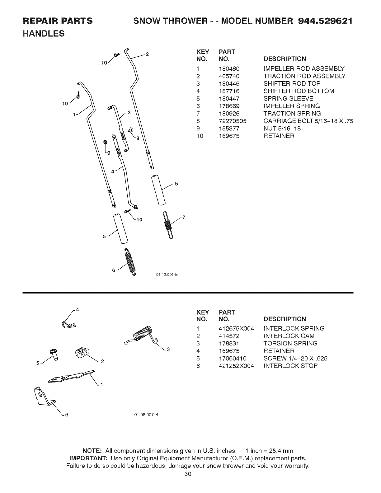
KEY PART
NO. NO.
1 180480
2 405740
3 180445
4 187716
5 180447
6 178669
7 180926
8 72270505
9 155377
10 169675
DESCRIPTION
IMPELLER ROD ASSEMBLY
TRACTION ROD ASSEMBLY
SHIFTER ROD TOP
SHIFTER ROD BOTTOM
SPRING SLEEVE
IMPELLER SPRING
TRACTION SPRING
CARRIAGE BOLT 5/16-18 X .75
N UT 5/16-18
RETAINER
01.12.001-E
01.08.007-B
-3
KEY PART
NO. NO. DESCRIPTION
1 412675X004 INTERLOCK SPRING
2 414572 INTERLOCK CAM
3 178831 TORSION SPRING
4 169675 RETAINER
5 17060410 SCREW 1/4-20 X .625
6 421252X004 INTERLOCK STOP
NOTE: All component dimensions given in U.S. inches. 1 inch = 25.4 mm
IMPORTANT: Use only Original Equipment Manufacturer (O.E.M.) replacement parts.
Failure to do so could be hazardous, damage your snow thrower and void your warranty.
30
REPAIR PARTS
HANDLES
SNOW THROWER - - MODEL NUMBER 944,529621
01.05.004-C
2
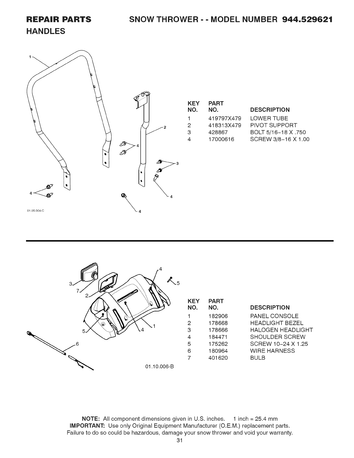
KEY PART
NO. NO. DESCRIPTION
1 419797X479 LOWER TUBE
2 418313X479 PIVOT SUPPORT
3 428867 BOLT 5/16-18 X .750
4 17000616 SCREW 3/8-16 X 1.00
01.10.O06-B
KEY PART
NO. NO. DESCRIPTION
1 182906 PANEL CONSOLE
2 178668 HEADLIGHT BEZEL
3 178666 HALOGEN HEADLIGHT
4 184471 SHOULDER SCREW
5 175262 SCREW 10-24 X 1.25
6 180964 WIRE HARNESS
7 401620 BULB
NOTE: All component dimensions given in U.S. inches. 1 inch = 25.4 mm
IMPORTANT: Use only Original Equipment Manufacturer (O.E.M.) replacement parts.
Failure to do so could be hazardous, damage your snow thrower and void your warranty.
31
REPAIR PARTS
DRIVE
SNOW THROWER - - MODEL NUMBER 944,529621
/
/
/
/
/
J
4.t
23_ 25
_24
41
39./_ 01.02.013-A
NOTE: All component dimensions given in U.S. inches. 1 inch = 25.4 mm
iMPORTANT: Use only Original Equipment Manufacturer (O.E.M.) replacement parts.
Failure to do so could be hazardous, damage your snow thrower and void your warranty.
32
REPAIR PARTS
DRIVE
SNOW THROWER --MODEL NUMBER 944,529621
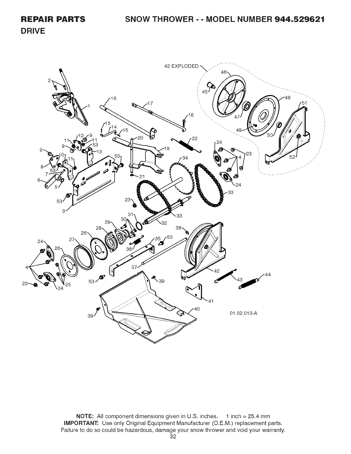
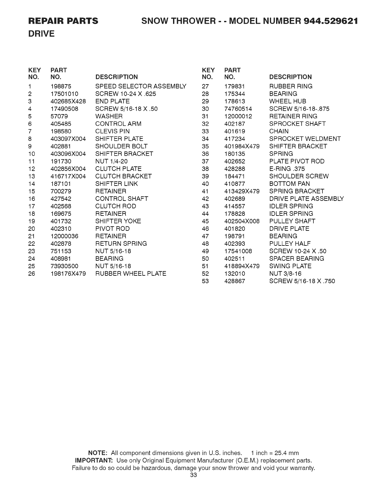
KEY PART
NO. NO.
1 198875
2 17501010
3 402685X428
4 17490508
5 57079
6 405485
7 198580
8 403097×004
9 402881
10 403096×004
11 191730
12 402856X004
13 416717X004
14 187101
15 700279
16 427542
17 402568
18 169675
19 401732
20 402310
21 12000036
22 402878
23 751153
24 408981
25 73930500
26 198176X479
KEY PART
DESCRIPTION NO. NO. DESCRIPTION
SPEED SELECTOR ASSEMBLY 27 179831 RUBBER RING
SCREW 10-24 X .625 28 175344 BEARING
END PLATE 29 178613 WHEEL HUB
SCREW 5/16-18 X .50 30 74760514 SCREW 5/16-18-.875
WASHER 31 12000012 RETAINER RING
CONTROL ARM 32 402187 SPROCKET SHAFT
CLEVIS PIN 33 401619 CHAIN
SHIFTER PLATE 34 417234 SPROCKET WELDMENT
SHOULDER BOLT 35 401984X479 SHIFTER BRACKET
SHIFTER BRACKET 36 180135 SPRING
NUT 1/4-20 37 402652 PLATE PIVOT ROD
CLUTCH PLATE 38 428288 E-RING .375
CLUTCH BRACKET 39 184471 SHOULDER SCREW
SHIFTER LINK 40 410877 BOTTOM PAN
RETAINER 41 413429X479 SPRING BRACKET
CONTROL SHAFT 42 402689 DRIVE PLATE ASSEMBLY
CLUTCH ROD 43 414557 IDLER SPRING
RETAINER 44 178828 IDLER SPRING
SHIFTER YOKE 45 402504X008 PULLEY SHAFT
PIVOT ROD 46 401820 DRIVE PLATE
RETAINER 47 198791 BEARING
RETURN SPRING 48 402393 PULLEY HALF
NUT 5/16-18 49 17541008 SCREW 10-24 X .50
BEARING 50 402511 SPACER BEARING
NUT 5/16-18 51 418894X479 SWING PLATE
RUBBER WHEEL PLATE 52 132010 NUT 3/8-16
53 428867 SCREW 5/16-18 X .750
NOTE: All component dimensions given in U.S. inches. 1 inch = 25.4 mm
iMPORTANT: Use only Original Equipment Manufacturer (O.E.M.) replacement parts.
Failure to do so could be hazardous, damage your snow thrower and void your warranty.
33

REPAIR PARTS
DRIVE
SNOW THROWER - - MODEL NUMBER 944,529621
01.03.002-A
KEY PART
NO. NO.
1 404923
la 404307
lb 9465M1
2 402691
3 174697
4 179830
5 146315
6 17490508
7 155443
8 189282
DESCRIPTION
AXLE ASSEMBLY (assy of la,lb)
AXLE SHAFT
ROLL PIN 3/16 X 1.50
SPROCKET
TH RUST WASH ER
BEARING
SCREW 5/16-18 X .625
SCREW 5/16-18 X .500
KLIK PIN 1/4X 1.50
SQUARE KEY
NOTE: All component dimensions given in U.S. inches. 1 inch = 25.4 mm
IMPORTANT: Use only Original Equipment Manufacturer (O.E.M.) replacement parts.
Failure to do so could be hazardous, damage your snow thrower and void your warranty.
34
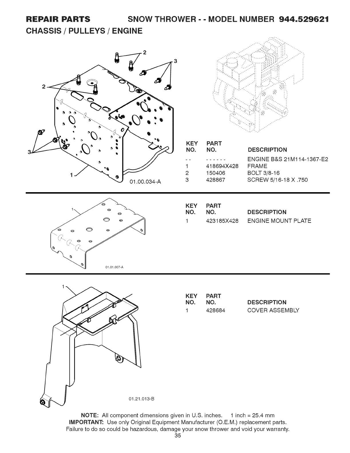
REPAIR PARTS SNOW THROWER - - MODEL NUMBER 944,529621
CHASSIS /PULLEYS /ENGINE
2
01.00.034-A
KEY PART
NO. NO.
1 418694X428
2 150406
3 428867
- _ .i _ ,,_ •
DESCRIPTION
ENGINE B&S 21M114-1367-E2
FRAME
BOLT 3/8-16
SCREW 5/16-18 X .750
01.01.007-A
KEY PART
NO. NO.
1 423185X428
DESCRIPTION
ENGINE MOUNT PLATE
KEY PART
NO. NO. DESCRIPTION
1 428684 COVER ASSEMBLY
01.21.013-B
NOTE: All component dimensions given in U.S. inches. 1 inch = 25.4 mm
iMPORTANT: Use only Original Equipment Manufacturer (O.E.M.) replacement parts.
Failure to do so could be hazardous, damage your snow thrower and void your warranty.
35
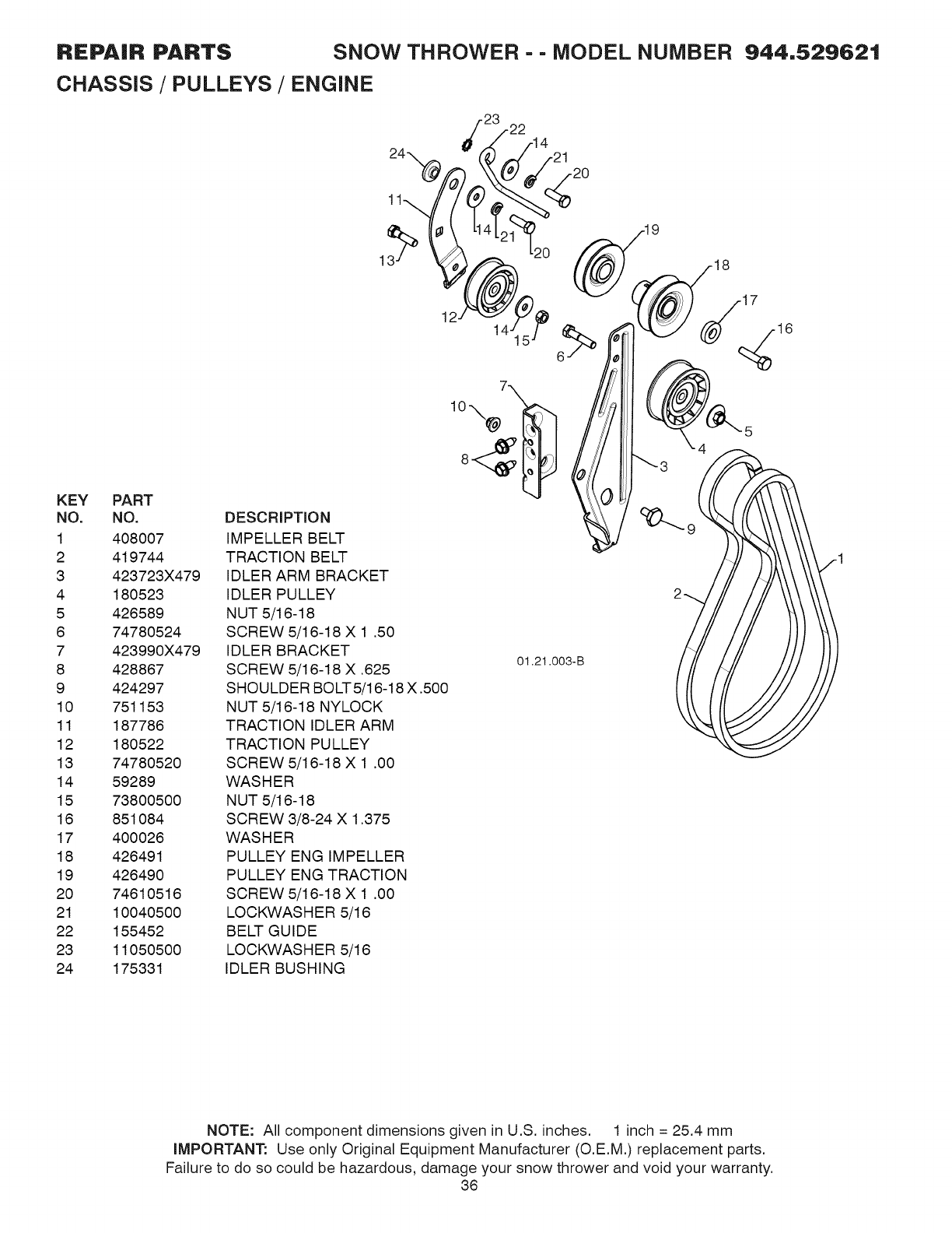
REPAIR PARTS SNOW THROWER --MODEL NUMBER 944,529621
CHASSIS /PULLEYS /ENGINE
KEY PART
NO. NO.
1 408007
2 419744
3 423723X479
4 180523
5 426589
6 74780524
7 423990X479
8 428867
9 424297
10 751153
11 187786
12 180522
13 74780520
14 59289
15 73800500
16 851084
17 400026
18 426491
19 426490
20 74610516
21 10040500
22 155452
23 11050500
24 175331
DESCRiPTiON
IMPELLER BELT
TRACTION BELT
IDLER ARM BRACKET
IDLER PULLEY
NUT 5/16-18
SCREW 5/16-18 X 1 .50
IDLER BRACKET
SCREW 5/16-18 X .625
SHOULDER BOLT 5/16-18 X .500
NUT 5/16-18 NYLOCK
TRACTION IDLER ARM
TRACTION PULLEY
SCREW 5/16-18 X 1 .00
WASHER
NUT 5/16-18
SCREW 3/8-24 X 1.375
WASHER
PULLEY ENG IMPELLER
PULLEY ENG TRACTION
SCREW 5/16-18 X 1 .00
LOCKVVASHER 5/16
BELT GUIDE
LOCKVVASHER 5/16
IDLER BUSHING
12
8
01.21.003-B
NOTE: All component dimensions given in U.S. inches. 1 inch = 25.4 mm
iMPORTANT: Use only Original Equipment Manufacturer (O.E.M.) replacement parts.
Failure to do so could be hazardous, damage your snow thrower and void your warranty.
38
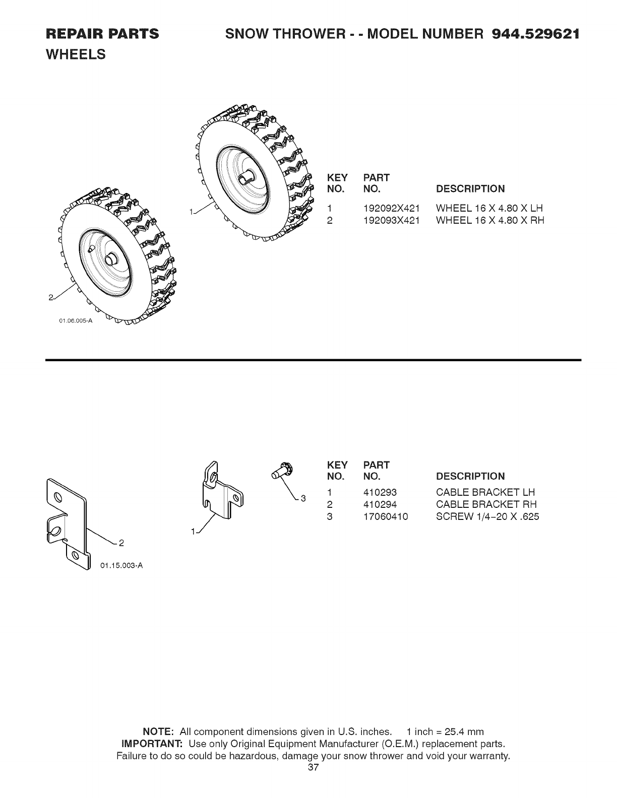
REPAIR PARTS
WHEELS
SNOW THROWER - - MODEL NUMBER 944,529621
KEY PART
NO. NO.
1
2
192092X421
192093X421
DESCRiPTiON
WHEEL 16 X 4.80 X LH
WHEEL 16 X 4.80 X RH
01.06.005-A
__ KEY PART
NO. NO.
1 410293
3 2 410294
3 17060410
DESCRIPTION
CABLE BRACKET LH
CABLE BRACKET RH
SCREW 1/4-20 X .625
01.15.003-A
NOTE: All component dimensions given in U.S. inches. 1 inch = 25.4 mm
iMPORTANT: Use only Original Equipment Manufacturer (O.E.M.) replacement parts.
Failure to do so could be hazardous, damage your snow thrower and void your warranty.
37
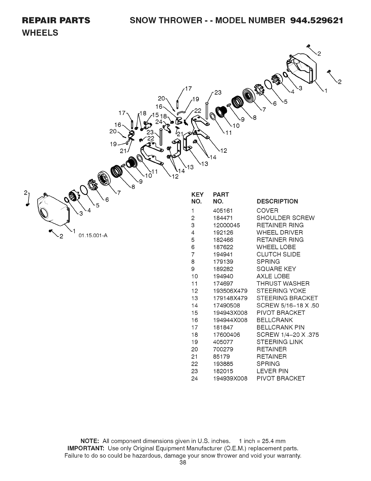
REPAIR PARTS
WHEELS
SNOW THROWER - - MODEL NUMBER 944,529621
2
01.15.001 -A
12
KEY PART
NO. NO. DESCRIPTION
1 405161 COVER
2 184471 SHOULDER SCREW
3 12000045 RETAINER RING
4 192126 WHEEL DRIVER
5 182466 RETAINER RING
6 187622 WHEEL LOBE
7 194941 CLUTCH SLIDE
8 179139 SPRING
9 189282 SQUARE KEY
10 194940 AXLE LOBE
11 174697 THRUST WASHER
12 193506X479 STEERING YOKE
13 179148X479 STEERING BRACKET
14 17490508 SCREW 5/16-18 X .50
15 194943X008 PIVOT BRACKET
16 194944X008 BE LLC RAN K
17 181847 BELLCRANK PIN
18 17600406 SCREW 1/4-20 X .375
19 405077 STEERING LINK
20 700279 RETAINER
21 85179 RETAINER
22 193885 SPRING
23 182015 LEVER PIN
24 194939X008 PIVOT BRACKET
NOTE: All component dimensions given in U.S. inches. 1 inch = 25.4 mm
iMPORTANT: Use only Original Equipment Manufacturer (O.E.M.) replacement parts.
Failure to do so could be hazardous, damage your snow thrower and void your warranty.
38
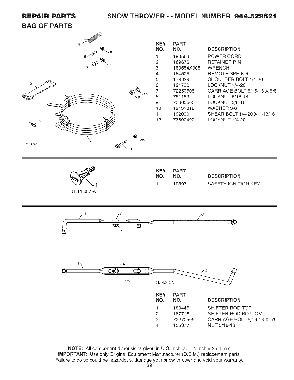
REPAIR PARTS
BAG OF PARTS
SNOW THROWER - - MODEL NUMBER 944,529621
2
01 14.003-B
KEY PART
NO. NO.
1 198563
2 169675
3 180684X008
4 184505
5 179829
6 191730
7 72250505
8 751153
9 73800600
10 19131316
11 192090
12 73800400
DESCRiPTiON
POWER CORD
RETAINER PIN
WRENCH
REMOTE SPRING
SHOULDER BOLT 1/4-20
LOCKNUT 1/4-20
CARRIAGE BOLT 5/16-18 X 5/8
LOCKNUT 5/16-18
LOCKNUT 3/8-16
WASHER 3/8
SHEAR BOLT 1/4-20 X 1-13/16
LOCKNUT 1/4-20
01.14.007-A
KEY PART
NO. NO.
1 193071
DESCRIPTION
SAFETY IGNITION KEY
12
O1.,
L_2.56_-_ 01.14.012-A
KEY PART
NO. NO.
1 180445
2 187716
3 72270505
4 155377
DESCRIPTION
SHIFTER ROD TOP
SHIFTER ROD BOTTOM
CARRIAGE BOLT 5/16-18 X .75
NUT 5/16-18
NOTE: All component dimensions given in U.S. inches. 1 inch = 25.4 mm
iMPORTANT: Use only Original Equipment Manufacturer (O.E.M.) replacement parts.
Failure to do so could be hazardous, damage your snow thrower and void your warranty.
39
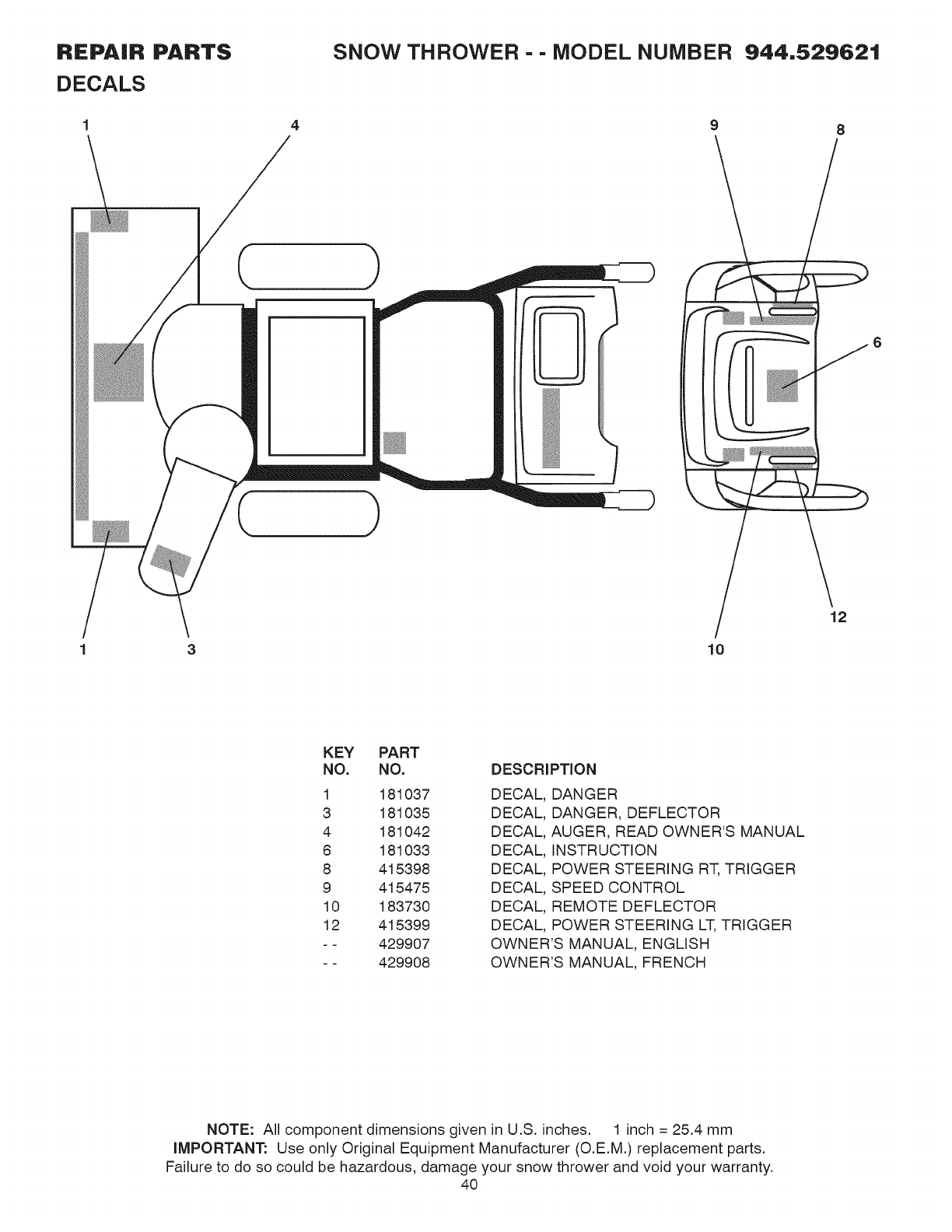
REPAIR PARTS
DECALS
SNOW THROWER - - MODEL NUMBER
9
944,529621
8
3/
10
12
KEY PART
NO. NO.
1 181037
3 181035
4 181042
8 181033
8 415398
9 415475
10 183730
12 415399
- - 429907
- - 429908
DESCRIPTION
DECAL, DANGER
DECAL, DANGER, DEFLECTOR
DECAL, AUGER, READ OWNER'S MANUAL
DECAL, iNSTRUCTION
DECAL, POWER STEERING RT, TRIGGER
DECAL, SPEED CONTROL
DECAL, REMOTE DEFLECTOR
DECAL, POWER STEERING LT,TRIGGER
OWNER'S MANUAL, ENGLISH
OWNER'S MANUAL, FRENCH
NOTE: All component dimensions given in U.S. inches. 1 inch = 25.4 mm
iMPORTANT: Use only Original Equipment Manufacturer (O.E.M.) replacement parts.
Failure to do so could be hazardous, damage your snow thrower and void your warranty.
40
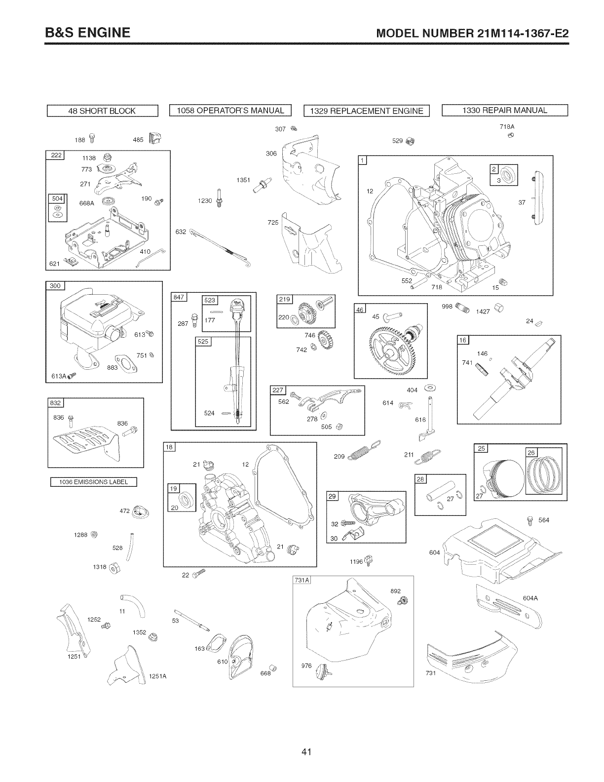
B&S ENGINE MODEL NUMBER 21Ml14-1367-E2
48 SHORT BLOCK J
621
613A_
83L_J 836
I lO36 EMISSIONS LABEL I
1288 _@ iJ
528 ,,,ii,,
1318 ,_'
L_
'\, 1252
1251
11 ,,
1352_
1251A
[ 1058 OPERATOR'S MANUAL ] [ 1329 REPLACEMENT ENGINE
307
.... 2;:J_ 529 _,_
306 , --.
I 1330 REPAIR MANUAL [
718A
1351 _'
1230 ;
632 c_
725
177
524
\
505 @
M
552
,\,j ....
404 L&
614 {_ :_,
616 i
998% 1427 (_
146
741%
37
24_
21
\
22
163(I
610
12
976@
209_' 211
29
_392__--_-
13o
1196@
892
'_ 27
6O4
564
_;'-._ _L'_"_. 604A
/
/
/
.... 2::...... -
41
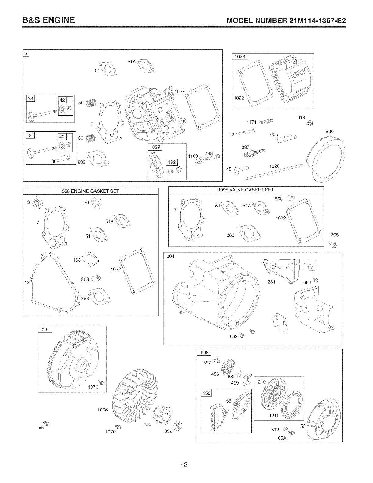
B&S ENGINE MODEL NUMBER 21Ml14-1367-E2
i11111:]111111_111_1:I_
.... 666(/19
51
,,>.......o) 1026 ..........:::::::::_
45 ,i(b,.-- :::::::::::::.:.....
358 ENGINE GASKET SET
,F <
[,
"\_oi) S
20
1070
6_
1oo5
1070
455
1095 VALVE GASKET SET
868 ,, ._
1022
883 305
459
56
12
1211
592 _©
65A
42
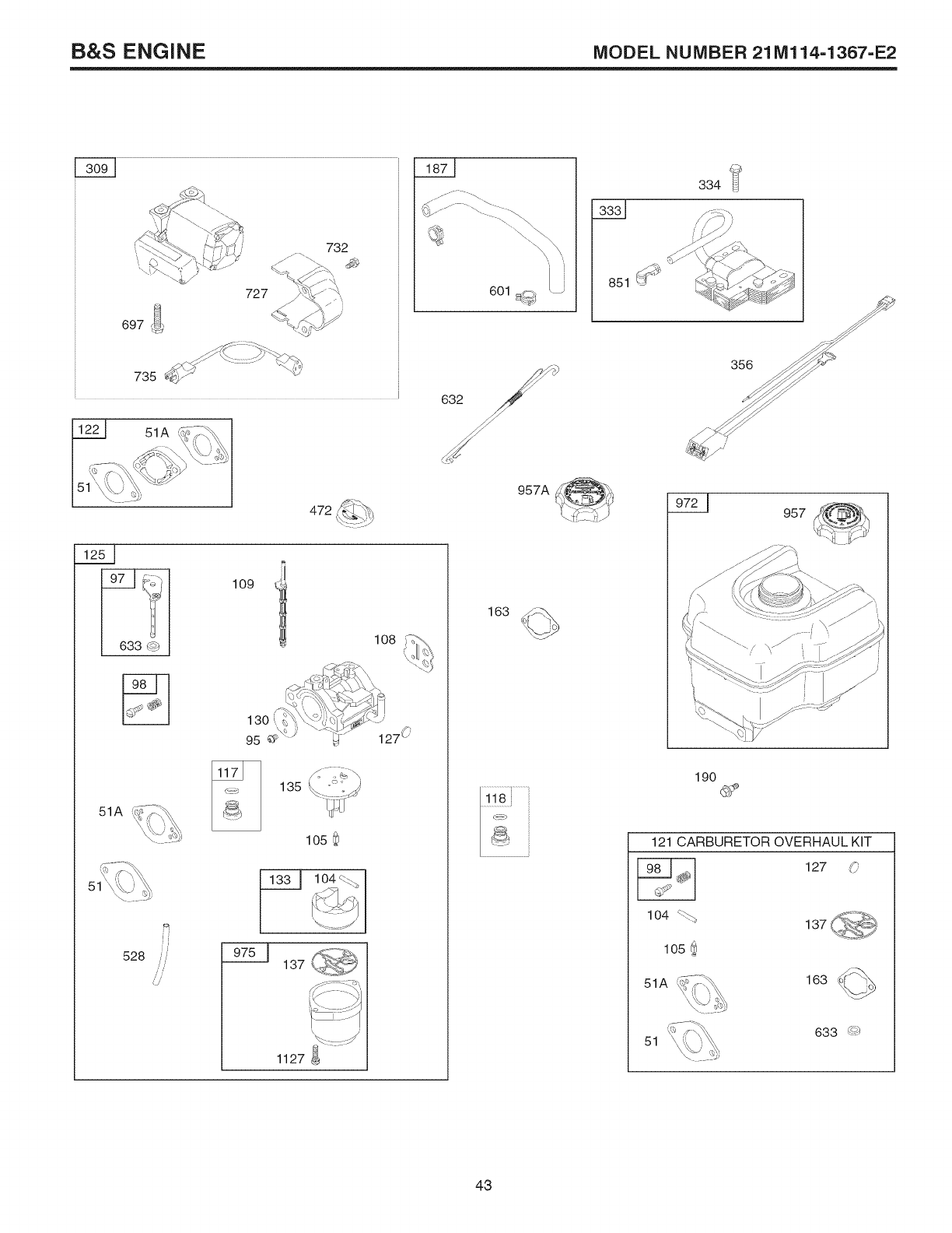
B&S ENGINE MODEL NUMBER 21Ml14-1367=E2
732
601 _
3331
334
51A
633 C_
51A
528
472
109
108
13O
95
135
105
975 _ 137
1127
957A
957
190
121 CARBURETOR OVERHAUL KIT
127 O
lO4 _%_
105 ._
51A 163
51 633 g_
43
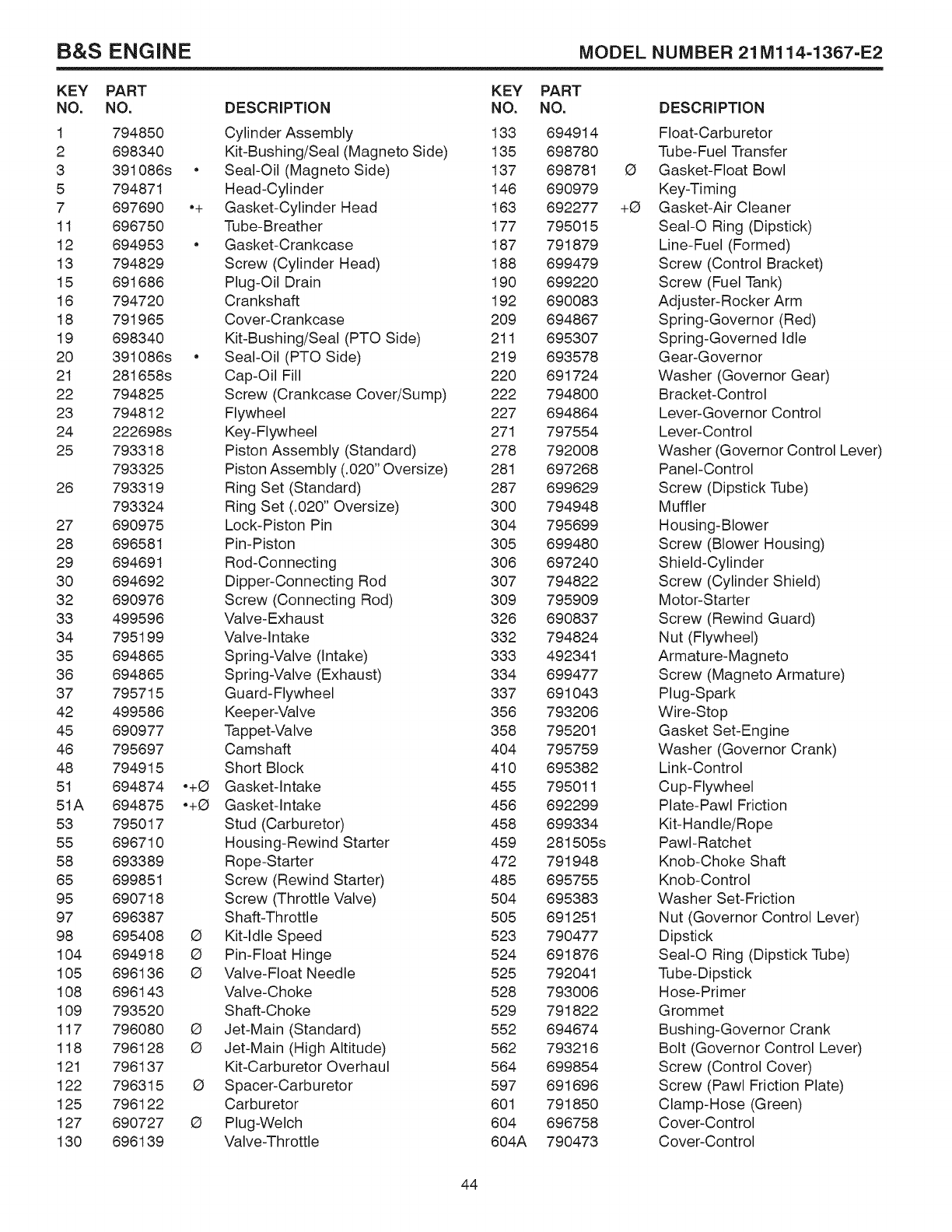
B&S ENGINE MODEL NUMBER 21Ml14-1367-E2
KEY PART
NO. NO.
1 794850
2 898340
3 391088s
5 794871
7 897890
11 898750
12 894953
13 794829
15 691686
18 794720
18 791965
19 898340
20 391088s
21 281858s
22 794825
23 794812
24 222698s
25 793318
793325
28 793319
793324
27 890975
28 898581
29 894891
30 894892
32 890978
33 499598
34 795199
35 894885
36 694865
37 795715
42 499586
45 690977
46 795697
48 794915
51 694874
51A 894875
53 795017
55 898710
58 893389
85 899851
95 890718
97 898387
98 895408
104 894918
105 696138
108 898143
109 793520
117 796080
118 796128
121 796137
122 796315
125 796122
127 890727
130 898139
DESCRiPTiON
Cylinder Assembly
Kit-Bushing!Seal (Magneto Side)
• Seal-Oil (Magneto Side)
Head-Cylinder
•+ Gasket-Cylinder Head
Tube-Breather
• Gasket-Crankcase
Screw (Cylinder Head)
Plug-Oil Drain
Crankshaft
Cover-Crankcase
Kit-Bushing!Seal (PTO Side)
• Seal-Oil (PTO Side)
Cap-Oil Fill
Screw (Crankcase Cover/Sump)
Flywheel
Key-Flywheel
Piston Assembly (Standard)
Piston Assembly (.020" Oversize)
Ring Set (Standard)
Ring Set (.020" Oversize)
Lock-Piston Pin
Pin-Piston
Rod-Connecting
Dipper-Connecting Rod
Screw (Connecting Rod)
Valve- Exhaust
Valve-In take
Spring-Valve (Intake)
Spring-Valve (Exhaust)
Guard-Flywheel
Keeper-Valve
Tappet-Valve
Camshaft
Short Block
•+O Gasket-Intake
•+O Gasket-Intake
Stud (Carburetor)
Housing-Rewind Starter
Rope-Starter
Screw (Rewind Starter)
Screw (Throttle Valve)
Shaft-Throttle
Q Kit-Idle Speed
Q Pin-Float Hinge
G Valve-Float Needle
Valve-Choke
Shaft-Choke
Q Jet-Main (Standard)
G Jet-Main (High Altitude)
Kit-Carburetor Overhaul
G Spacer-Carburetor
Carburetor
O Plug-Welch
Valve-Throttle
KEY
NO.
133
135
137
146
163
177
187
188
190
192
209
211
219
220
222
227
271
278
281
287
300
304
305
308
307
309
328
332
333
334
337
358
358
404
410
455
456
458
459
472
485
504
505
523
524
525
528
529
552
562
564
597
601
604
804A
PART
NO.
694914
698780
698781
690979
692277
795015
791879
699479
899220
890083
694867
895307
893578
691724
794800
694864
797554
792008
697268
699629
794948
795699
899480
897240
794822
795909
890837
794824
492341
899477
691043
793208
795201
795759
895382
795011
892299
899334
281505s
791948
895755
895383
691251
790477
691876
792041
793008
791822
694674
793216
899854
691696
791850
696758
790473
G
+G
DESCRiPTiON
Float-Carburetor
Tube-Fuel Transfer
Gasket-Float Bowl
Key-Timing
Gasket-Air Cleaner
SeaI-O Ring (Dipstick)
Line-Fuel (Formed)
Screw (Control Bracket)
Screw (Fuel Tank)
Adjuster-Rocker Arm
Spring-Governor (Red)
Spring-Governed Idle
Gear-Governor
Washer (Governor Gear)
Bracket-Control
Lever-Governor Control
Lever-Control
Washer (Governor Control Lever)
Panel-Control
Screw (Dipstick Tube)
Muffler
Housing-Blower
Screw (Blower Housing)
Shield-Cylinder
Screw (Cylinder Shield)
Motor-Starter
Screw (Rewind Guard)
Nut (Flywheel)
Armature-Magneto
Screw (Magneto Armature)
Plug-Spark
Wire-Stop
Gasket Set-Engine
Washer (Governor Crank)
Link-Control
Cup-Flywheel
Plate-Pawl Friction
Kit-Handle/Rope
PawI-Ratchet
Knob-Choke Shaft
Knob-Control
Washer Set-Friction
Nut (Governor Control Lever)
Dipstick
SeaI-O Ring (Dipstick Tube)
Tube-Dipstick
Hose-Primer
Grommet
Bushing-Governor Crank
Bolt (Governor Control Lever)
Screw (Control Cover)
Screw (Pawl Friction Plate)
Clamp-Hose (Green)
Cover-Control
Cover-Control
44
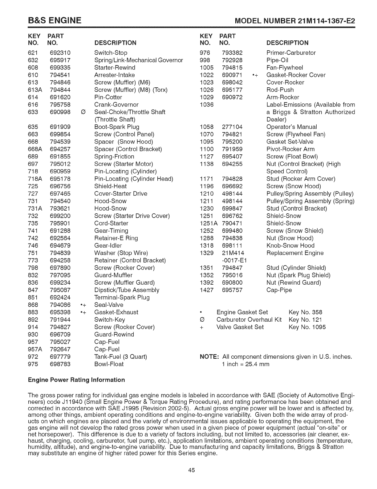
B&S ENGINE MODEL NUMBER 21Ml14-1367-E2
KEY PART
NO. NO.
621 692310
632 695917
608 699335
610 794541
613 794846
613A 794844
614 691620
616 795758
633 690998
635 691909
663 699854
668 794539
668A 694257
689 691855
697 795012
718 690959
718A 695178
725 696756
727 697465
731 794540
731A 793621
732 699200
735 795901
741 691288
742 692564
746 694679
751 794839
773 694258
798 697890
832 797095
836 699234
847 795087
851 692424
868 794086
883 695398
892 791944
914 794827
930 696709
957 795027
957A 792647
972 697779
975 698783
DESCRiPTiON
Switch-Stop
Spring!Link-Mechanical Governor
Starter-Rewind
Arrester-lntake
Screw (Muffler) (M6)
Screw (Muffler) (M8) (Torx)
Pin-Cotter
Crank-Governor
G Seal-Choke/Throttle Shaft
(Throttle Shaft)
Boot-Spark Plug
Screw (Control Panel)
Spacer (Snow Hood)
Spacer (Control Bracket)
Spring-Friction
Screw (Starter Motor)
Pin-Locating (Cylinder)
Pin-Locating (Cylinder Head)
Shield-Heat
Cover-Starter Drive
Hood-Snow
Hood-Snow
Screw (Starter Drive Cover)
Cord-Starter
Gear-Timing
Retainer-E Ring
Gear-Idler
Washer (Stop Wire)
Retainer (Control Bracket)
Screw (Rocker Cover)
Guard-Muffler
Screw (Muffler Guard)
Dipstick/Tube Assembly
Terminal-Spark Plug
•+ Seal-Valve
•+ Gasket-Exhaust
Switch-Key
Screw (Rocker Cover)
Guard-Rewind
Cap-Fuel
Cap-Fuel
Tank-Fuel (3 Quart)
Bowl-Float
KEY
NO.
976
998
1005
1022
1023
1026
1029
1036
1058
1070
1095
1100
1127
1138
1171
1196
1210
1211
1230
1251
1251A
1252
1288
1318
1329
1351
1352
1392
1427
PART
NO.
793382
792928
794815
690971
698042
695177
690972
277104
794821
795200
791959
695407
694255
794828
696692
498144
498144
699847
696762
790471
699480
794838
698111
21 M414
-0017-E1
794847
795016
690800
695757
o+
DESCRiPTiON
Primer-Carburetor
Pipe-Oil
Fan-Flywheel
Gasket-Rocker Cover
Cover-Rocker
Rod-Push
Arm-Rocker
Label-Emissions (Available from
a Briggs & Stratton Authorized
Dealer)
Operator's Manual
Screw (Flywheel Fan)
Gasket Set-Valve
Pivot-Rocker Arm
Screw (Float Bowl)
Nut (Control Bracket) (High
Speed Control)
Stud (Rocker Arm Cover)
Screw (Snow Hood)
Pulley/Spring Assembly (Pulley)
Pulley/Spring Assembly (Spring)
Stud (Control Bracket)
Shield-Snow
Shield-Snow
Screw (Snow Shield)
Nut (Snow Hood)
Knob-Snow Hood
Replacement Engine
Stud (Cylinder Shield)
Nut (Spark Plug Shield)
Nut (Rewind Guard)
Cap-Pipe
o
Q
+
Engine Gasket Set Key No. 358
Carburetor Overhaul Kit Key No. 121
Valve Gasket Set Key No. 1095
NOTE: All component dimensions given in U.S. inches.
1 inch = 25.4 mm
Engine Power Rating information
The gross power rating for individual gas engine models is labeled in accordance with SAE (Society of Automotive Engi-
neers) code J11940 (Small Engine Power & Torque Rating Procedure), and rating performance has been obtained and
corrected in accordance with SAE J1995 (Revision 2002-5). Actual gross engine power will be lower and is affected by,
among other things, ambient operating conditions and engine-to-engine variability. Given both the wide array of prod-
ucts on which engines are placed and the variety of environmental issues applicable to operating the equipment, the
gas engine will not develop the rated gross power when used in a given piece of power equipment (actual "on-site" or
net horsepower). This difference is due to a variety of factors including, but not limited to, accessories (air cleaner, ex-
haust, charging, cooling, carburetor, fuel pump, etc.), application limitations, ambient operating conditions (temperature,
humidity, altitude), and engine-to-engine variability. Due to manufacturing and capacity limitations, Briggs & Stratton
may substitute an engine of higher rated power for this Series engine.
45

SERVICE OTES
46

SERVICE NOTES
47

Just Call:
1-.800-.4-.MY-.HOME®
(1-800-469-4663)
24 hours a day, 7 days a week
For the repair of major brand appliances in your own home...
no matter who made it, no matter who sold it!
For your nearest Sears Parts and Service location,
to bring in products like vacuums, lawn equipment and electronics.
For Sears Parts &Service, to order the replacement parts,
accessories and owner's manuals that you need to do-it-yourself.
To purchase or inquire about a Sears Maintenance Agreement, call:
1-800-361-6665
9 a.m.-11 p.m. Mon.- Fd.,EST, 9 a.m.- 4 p.m. Sat.
Pour service en frangais:
1-800-LE-FOYER Mc
(1=800=533=6937)
WWW,SeSrS,C8
(_)/TMTrademarks of Sears, Roebuck and Co. used under license by Sears Canada
MDMarque d_pos_e /MCMarque de commerce de Sears, Roebuck and Co. utilis_e en vertu d'une licence de Sears Canada
429907 09.01.09 SR Printed in the U.S.A.
