CRAFTSMAN Saw Radial Manual L0912100
User Manual: CRAFTSMAN CRAFTSMAN Saw Radial Manual CRAFTSMAN Saw Radial Owner's Manual, CRAFTSMAN Saw Radial installation guides
Open the PDF directly: View PDF ![]() .
.
Page Count: 21
Sears
OWNERS
MANUAL
MODEL NO.
901.23181
Serial
Nur"ber_
Seriat Number
may be fodnd on the
machine nameplate
located at the front
of the table frame.
Please record it
above for your records,
CAUT!ON:
Read Rules for
Safe Operation
and Instructions
Carefully
_R_FTSMAN®
instruct
a
WARNING: FOR YOUR OWN SAFETY, READ THIS MANUAL BEFORE OPERATING TOOL.
REVIEW SAFETY RULES AND OPERATING INSTRUCTIONS FREQUENTLY.
12" RADIAL ARM SAW
This booklet is provided for your convenience
in the use and care of your new Craftsman Saw.
,hose instructions include operation, usage,
precautions,, preventive maintenance, main-
tens 1co z.£' "_ther pertinrnt data to assist you
ia assuricg tong life and c":pcqdable service
from your saw.
INDEX
Power Connection and Grounding ............ 2
Unpacking, Set Up and Specifications ......... 3
Adjustments and Alignment ................ 4-7
Operating Instructions ..................... 9-12
Rules for Operation & Maintenance .......... 8
Parts Drawing and Lists.... •................ 14-18
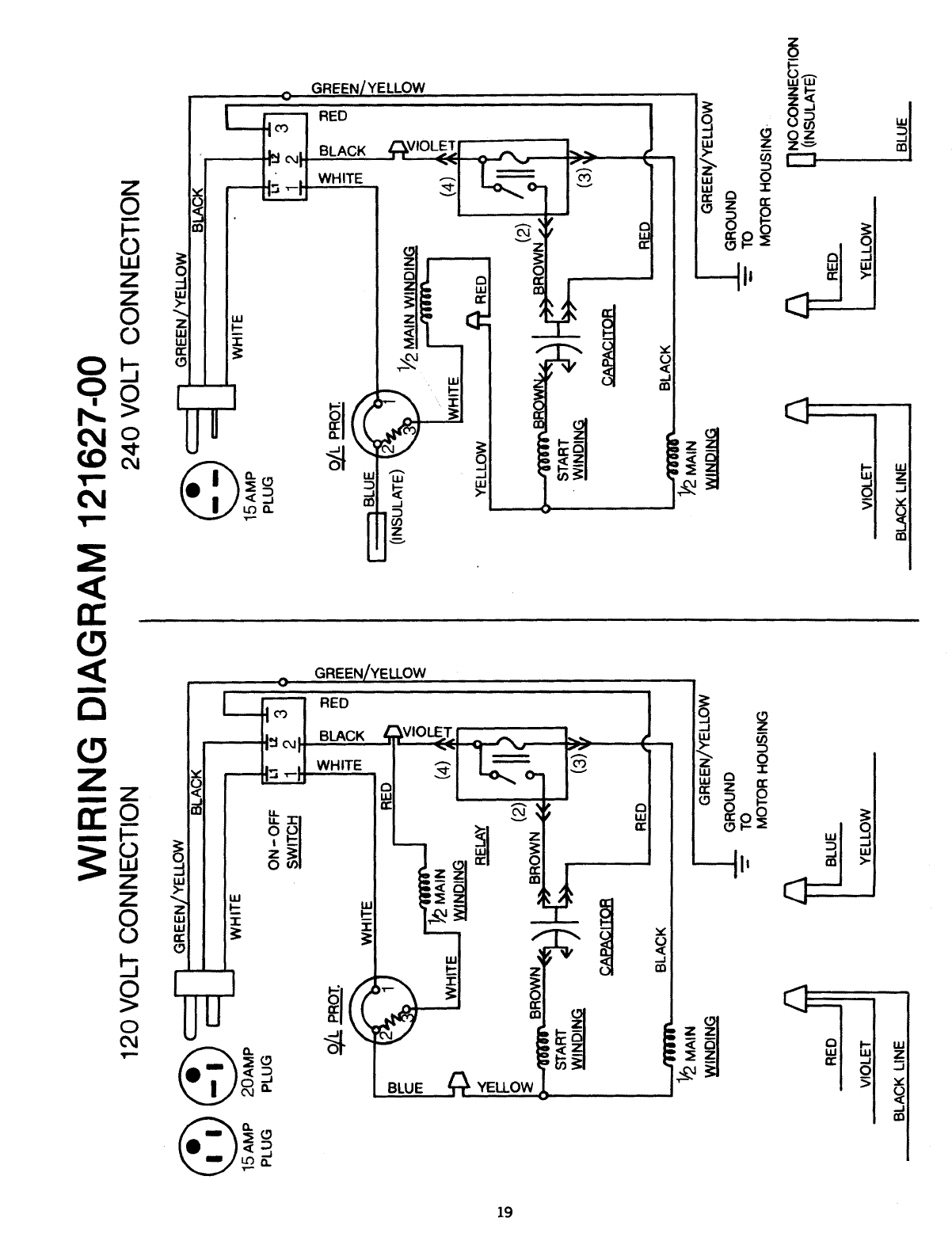
Motor Connection Diagram ................. 19
Motor Trouble Shooting Chart ............... 13
CAUTION
For purposes of clarity, the
lower guard is omitted
from the photographs in-
side this manual. However,
ALL cuts must be made
with both the upper and
lower guards in place.
MODEL NO. PHASE VOLTAGE
901.23181 1ph 120--208/240 VOLT 60 CY.
SINGLE PHASE POWER CONNECTIONS AND GROUNDING
This tool should be grounaed while in use to protect the operator from
electric shock.
We recommend that you NEVER dissemble the tool or try to do any
rewiring in the electrical system. Any such repairs should be perform-
ed only by Sears Service Centers or other qualified service organi-
zations. Should you be determined to make a repair yourself,
remember that the green colored wire is the "grounding" wire. Never
connect this green wire to a "live" terminal.
In the event of a malfunction or breakdown, grounding provides a
path of least resistance for electric current to reduce the risk of electric
shock. This tool is equipped with an electric cord having an
equipment-grounding conductor and a grounding plug. The plug must
be plugged into a matching outlet that is properly installed and
grounded in accordance with all local codes and ordinances. Do not
modify the plug provided -- if it will not fit the outlet, have the proper
outlet installed by a qualified electrician. Improper connection of the
equipment-grounding conductor can result in a risk of electric shock.
The conductor with insulation having an outer surface that is green
with or without yellow stripes is the equipment-grounding conductor.
If repair or replacement of the electric cord or plug is necessary, do
not connect the equipment-grounding conductor to a live terminal.
Check with a qualified electrician or serviceman if the grounding
instructions are not completely understood, or if in doubt as to
whether the tool is properly grounded. Use only 3-wire extension
cords that have 3-prong grounding plugs and 3-pole receptacles that
accept the tool's plug. Repair or replace damaged or worn cord
immediately.
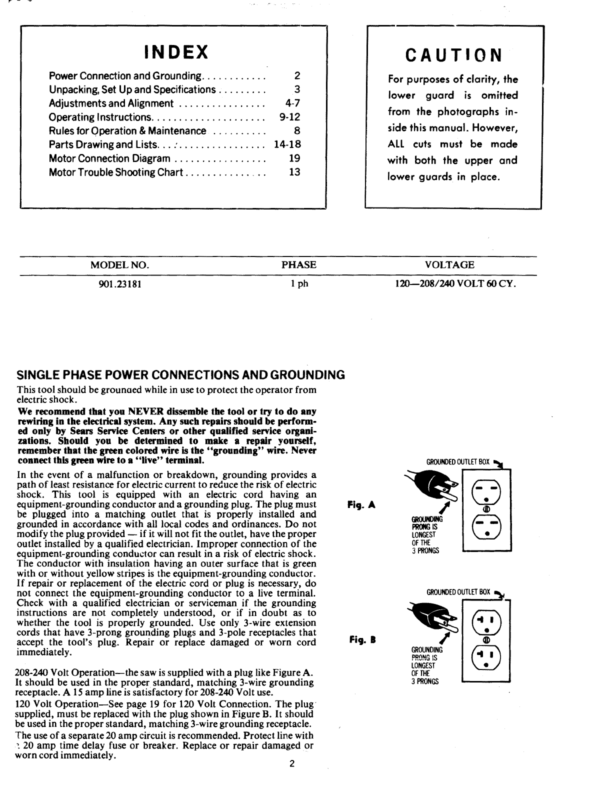
208-240 Volt Operation--the saw is supplied with a plug like Figure A.
It should be used in the proper standard, matching 3-wire grounding
receptacle. A 15 amp line is satisfactory for 208-240 Volt use.
120 Volt Operation--See page 19 for 120 Volt Connection. The plug
supplied, must be replaced with the plug shown in Figure B. It should
be used in the proper standard, matching 3-wire grounding receptacle.
The use of a separate 20 amp circuit is recommended. Protect line with
•. 20 amp time delay fuse or breaker. Replace or repair damaged or
worn cord immediately. 2
Fig. A
GROUNDEDOUTLETBOXI_l
/
GROtINOING
PRONGIS
LONGEST
OFTHE
3PRONGS
©
®
©
GROUNDEDOUTLETBOX
GROUNDING
P,,_NGIS
LONGEST
OFTHE
3PRONGS
©
@
UNPACKING AND SET-UP iNSTRUCTiONS
Your Craftsman Saw has been completely assembled,
tes"_d and table top kerfed at the f'a_ ,'%" and then partially
o,. ;,asembled for packaging and shipment,
We suggest the following procedure:
1, Turn the Elevating Handle at top of column count_'r-
clockwise a few turns to reIease the motor box and re-
move it from under the arm. (Do not discard the ,;_ta[
plate or guard found urrder motor box.)
2, Remove the Arm End Cap but do not disconnect the
,_'_ads to the switch, Insert rolIerhead yoke ar_I motor
a_sembly into the arm. being careful not to damage the
rip pointer on fight side, and rail to extreme back of arm
against column. Lock the entire assembly with the rip
lock, Replace arm cad cap.
3_
4_
Swing arm and position at right angle to guide fence at
0aon miter scale. Locate miter latch in column slot.
Securely lock arm with arm clamp handle.
Place machine on its back (column on floor) and attach
legs wkh four (4) bolts to each leg. Now place machine
in an upright position on its legs. To prevent forward
creeping of the saw carriage, tilt the saw backward by
shimming under the front of table frame or front legs if
so equipped, Use sturdy outrigger supports if any table
extensions are attached to the saw,
AI1electrica[ co_mections have been made for you to operate
your machine on 208 to 240 volts power supply. For change
to I20 volt on single phase models refer to connection dia-
gram on the motor name olate, and page 19 of this manual.
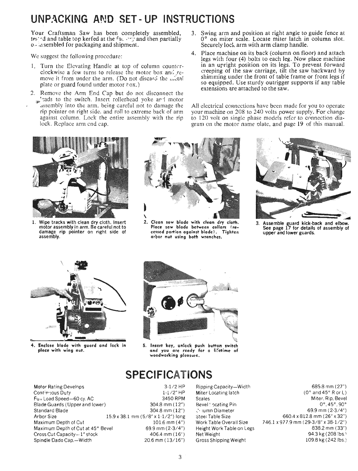
1. Wipe tracks with clean dry cloth, insert
motor assembly in arm. Be careful not to
damage rip pointer on right side of
assemNy.
3. Assemble guard kick-back and elbow.
See page 17 for details of assembly of
upper an_ lower guards.
SPECIFICATIONS
Motor Rating Devehps 3-1/2 HP
Cont;m,,ous Duty 1_.1./2" HP
Fu,, Load Speed--60 cy. AC 3450 RPM
Blade Guards (Upper and lower) 304.8 mm (12")
Standard Blade 304.8 mm (12")
Arbor Size 15,9 x 38.1 mm ( 5/8" x l- 1/2") long
Maximum Depth of Cut 101.6 mm (4 _)
Maximum Depth of Cut at 45 ° Bevel 69.9 mm (2.3/4 ")
Cross Cut Capacity- 1" stock 405.4 mm (16")
Spindle Dado Cap,--Width 20.6 mm( 13/15 ")
Ripping Capacity--Width
Miter Locating latch
Scales
Bevel I ocating Pin
,'. _umn Diameter
5teel Table Size
Work Table Overall Size
Height Work Table on Legs
Net Weight
Gross Shipping Weight
685,8 rnm (27")
(0 ° and 45 ° Ror L)
Miter, Rip. Bevel
0% 45 _ ,90 °
69.9 mm (2-3/4")
660.4 x 8t2.8 mm (26 _ x 32")
746.1 x 977,9 mm (29-3/8" x 38-1/2")
838.2 mm (33 _)
94.3 kg (208 tbs._
!.09.8 kg (242 Ibs.),
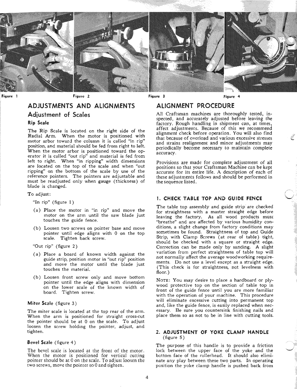
ADJUSTMENTS AND ALIGNMENTS
Adiusfmenf of Scales
Rip Scale
The Rip Scale is located on the right side of the
Radial Arm. When the motor is positioned with
motor arbor toward the column it is called "in rip"
position, and material should be fed from right to left.
When the motor arbor is positioned toward the op-
erator it is called "out rip" and material is fed from
left to right. When "in ripping" width dimensions
are located on the top of the scale and when "out
ripping" on the bottom of the scale by use of the
reference pointers. The pointers are adjustabIe and
must be readjusted only when gauge (thickness) of
blade is changed.
To adjust:
"In rip" (figure I)
(a) Place the motor in "in rip" and move the
motor on the arm until the saw blade just
touches the guide fence.
(b) Loosen two screws on pointer base and move
pointer until edge aligns with 0 on the top
scale. Tighten back screw.
"Out rip" (figure 2)
(a) Place a board of known width against the
guide strip, position motor in "out rip" position
and move the motor until the blade just
touches the material.
(b) Loosen front screw only and move bottom
pointer until the edge aligns with dimension
on the lower scale of the known width of
board. Tighten screw.
Miter Scale (figure 3)
The miter scale is located at the top rear of the arm.
When the arm is positioned for straight cross-cut
the pointer should be at 0 on the scale. To adjust
loosen the screw holding the pointer, adjust, and
tighten.
Bevel Scale (figure 4)
The bevel scale is Iocated at the front of the motor.
When the motor is positioned for verticaI cutting
pointer should be at 0 on the scale. To adjust Ioosen the
two screws, move the pointer to 0 and tighten.
ALIGNMENT PROCEDURE
Atl Craftsman machines are thoroughly tested, in-
spected,and accurately adjusted before leaving the
factory. Rough handling in shipment can, at times,
affect adjustments. Because of this we recommend
alignment check before operation. You will also find
that because of overload and various excessive stresses
and strains realignment and minor adjustments may
periodically become necessary to maintain complete
accuracy.
Provisions are made for complete adjustment of all
positions so that your Craftsman Machine can be kept
accurate for its entire life. A description of each of
these adjustments follows and should be performed in
the sequence listed.
1. CHECK TABLE TOP AND GUIDE FENCE
The table top assembly and guide strip' are checked
for straightness with a master straight edge before
leaving the factory. As all wood products must
"breathe" and are affected by various humidity con-
ditions, a Might change from factory conditions may
sometimes be found. Straightness of top and Guide
Strip, with Clamp Screws (at rear of table) tight,
should be checked with a square or straight edge.
Correction can be made only by sanding. A slight
variation from perfect straightness of table top will
not normally affect the average woodworking require-
ments. Do not use a leveI except as a straight edge.
(This check is for straightness, not levelness with
floor. )
NOTE: You may desire to place a hardboard or ply-
wood protective top on the section of table top in
front of the guide fence until you are more familiar
with the operation of your machine. This procedure
wilt eliminate excessive cutting into permanent top
and, Iike the guide fence, is easily replaced when nec-
essary. Be sure you countersink finishing nails and
place them so as not to be in line with cutting tools.
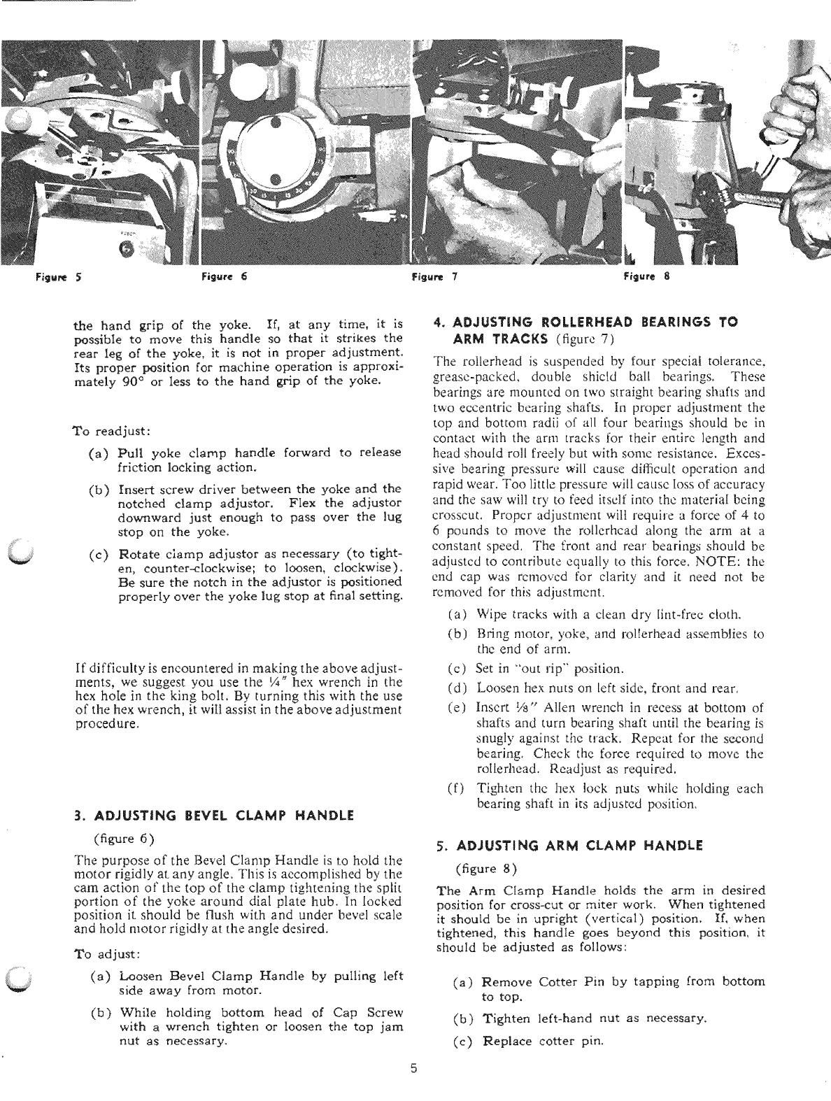
2. ADJUSTMENT OF YOKE CLAMP HANDLE
(figure 5)
The purpose of this handle is to provide a friction
lock between the upper face of the yoke and the
bottom face of the roilerhead. It should also eIiml-
hate any pIay between these two parts. In operating
position the yoke clamp handle is pushed back from
2
i _ :i¸
/
the hand grip of the yoke. If, at any time, it is
possible to move this handle so that it strikes the
rear leg of the yoke, it is not in proper adjustment.
Its proper position for machine operation is approxi-
mately 90 _ or Iess to the hand grip of the yoke.
To readjust :
(a) Pull yoke clamp handle forward to release
friction locking action.
(b) Insert screw driver between the yoke and the
notched clamp adjustor. FIex the adjustor
downward just enough to pass over the lug
stop on the yoke,
(c) Notate clamp adjustor as necessary (to tight-
en, counter-clockwise; to loosen, clockwise).
Be sure the notch in the adjustor is positioned
properly over the yoke lug stop at final setting.
If difficulty is encountered in making the above adjust-
ments, we suggest you use the ¼" hex wrench in the
hex hoIe in the king bolt. By turning this with the use
of the hex wrench, it wiIl assist in the above adjustment
procedure.
3. ADJUSTING BEVEL CLAMP HANDLE
(figure 6 )
The purpose of the Bevel Clamp Handle is to hold the
motor rigidly at any angIe, This is accomplished by the
cam action of the top of the clamp tightening the split
portion of the yoke around dial plate hub. In locked
position it should be flush with and under bevel scale
and hold motor rigidly at the angle desired.
To adjust :
(a) Loosen Bevel Clamp Handle by pulling left
side away from motor.
(b) While holding bottom head o[ Cap Screw
with a wrench tighten or Ioosen the top jam
nut as necessary.
4. ADJUSTING ROLLERHEAD BEARINGS TO
ARM TRACKS (figure 7)
The rollerhead is suspended by four speciM tolerance.
grease-packed_ double shic[d bali bearings, These
bearings are mounted on two straight bearing s!mfts and
two eccentric bearing shafts. In proper adjustment the
top and bottom radii of all four bearings should be in
contact with the arm tracks for their entire length and
head shou[d roll freely but with some resistance. Exces-
sive bearing pressure will cause digicult operation and
rapid wear. Too little pressure will cause Ioss of accuracy
and the saw will try to feed itself into the material being
crosscut, Propcr adjustment wilt require a force of 4to
6pounds to move the rollerhcad along the arm at a
constant speed, The front and rear bearings should be
adjustcd to contribute equally to this force, NOTE: the
end cap was rcmovcd for clarity and it need not be
removed for this adjustment.
(a) Wipe tracks with a clean dry lint-free ctoth.
(b) Bring motor, yoke, and rolIerhead assemblies to
the end of arm.
(c) Set in _'out rip" position.
(d) Loosen hex nuts on left side, front and rear,
(e) Insert 1is" Alien wrench in recess at bottom of
shafts and turn bearing shaft until the bearing is
snugly against the track. Repeat for the second
bearing, Check the force required to move the
roIlerhead. Readjust as required,
(f) Tighten the hex lock nuts white hoIding each
bearing shaft in its adjusted positiom
5. ADJUSTING ARM CLAMP HANDLE
(figure 8)
The Arm Clamp Handle holds the arm in desired
position for cross-cut or miter work. When tightened
it should be in upright (vertical) position. If, when
tightened, this handle goes beyond this position, it
should be adjusted as follows:
(a) Remove Cotter Pin by tapping from bottom
to top.
(b) Tighten left-hand nut as necessary.
(e) Replace cotter pin.
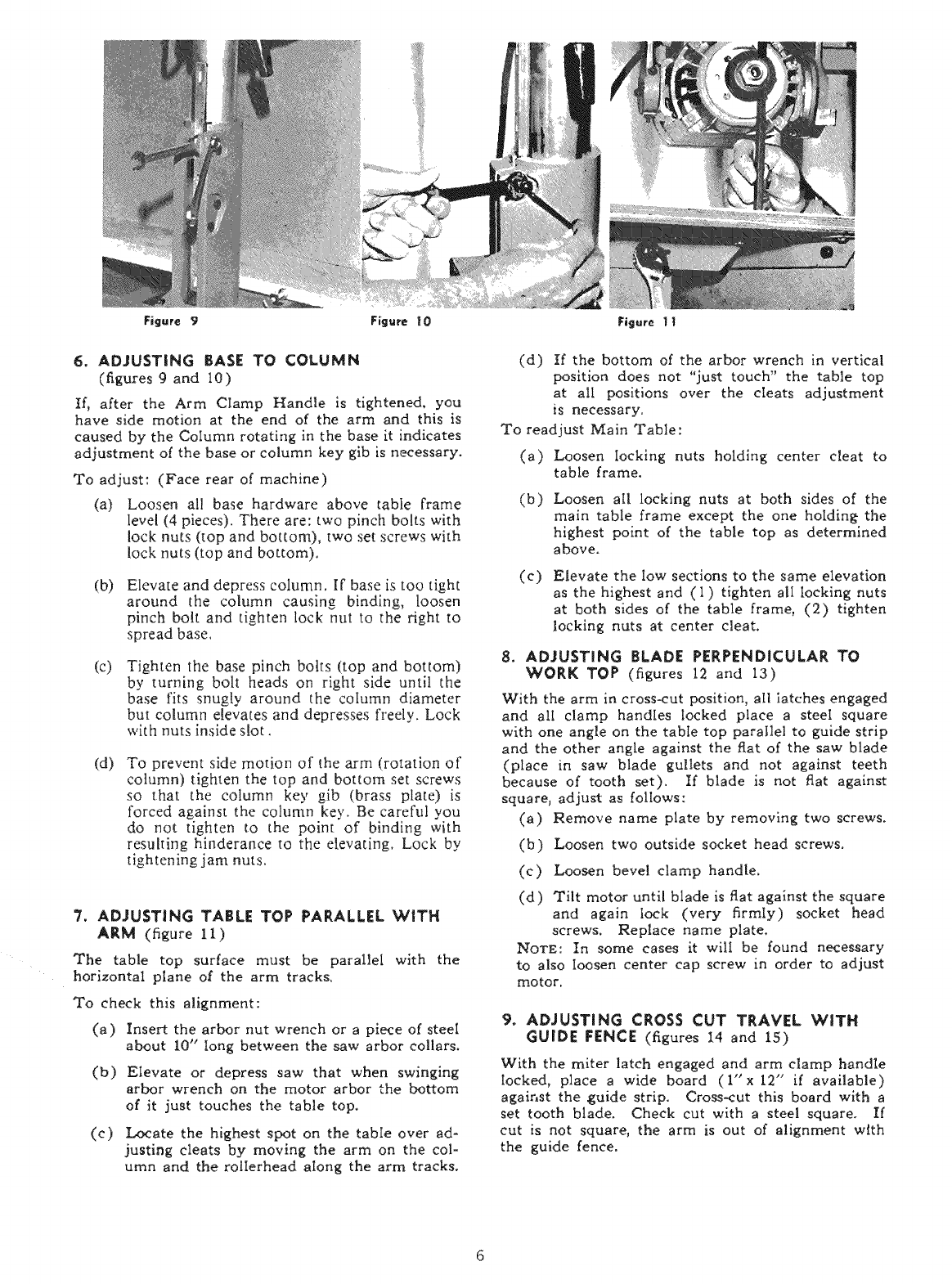
6. ADJUSTING BASE TO COLUMN
(figures 9and 10)
If, after the Arm CIamp Handle is tightened, you
have side motion at the end of the arm and this is
caused by the Column rotating in the base it indicates
adjustment of the base or column key glb is necessary.
To adjust: (Face rear of machine)
(a) Loosen all base hardware above table frame
level (4 pieces). There are: two pinch bolts with
lock nuts (top and bottom), two set screws with
lock nuts (top and bottom).
(b) Elevate and depress column. If base is too tight
around the column causing binding, loosen
pinch bolt and tighten lock nut to the right to
spread base.
(c) Tighten the base pinch bolts (top and bottom)
by turning bolt heads on right side until the
base fits snugly around the column diameter
but column elevates and depresses freely. Lock
with nuts inside slot.
(d) To prevent side motion of the arm (rotation of
column) tighten the top and bottom set screws
so that the coIumn key gib (brass plate) is
forced against the column key. Be careful you
do not tighten to the point of binding with
resulting hinderance to the elevating. Lock by
tightening jam nuts.
7. ADJUSTING TABLE TOP PARALLEL WITH
ARM (figure 11)
The table top surface must be parallel with the
horizontal ptane of the arm tracks.
To check this alignment:
(a) Insert the arbor nut wrench or a piece of steel
about 10" long between the saw arbor collars.
(b) Elevate or depress saw that when swinging
arbor wrench on the motor arbor the bottom
of it just touches the table top.
(c) Locate the highest spot on the table over ad-
justing cleats by moving the arm on the col-
umn and the rolierhead along the arm tracks.
(d) If the bottom of the arbor wrench in vertical
position does not "just touch" the table top
at all positions over the cleats adjustment
is necessary.
To readjust Main Table:
(a) Loosen Iocking nuts holding center cleat to
table frame.
(b)
(c)
Loosen all locking nuts at both sides of the
main table frame except the one holdin_ the
highest point of the table top as determined
above,
Elevate the low sections to the same elevation
as the highest and (1) tighten all locking nuts
at both sides of the table frame, (2) tighten
locking nuts at center cleat.
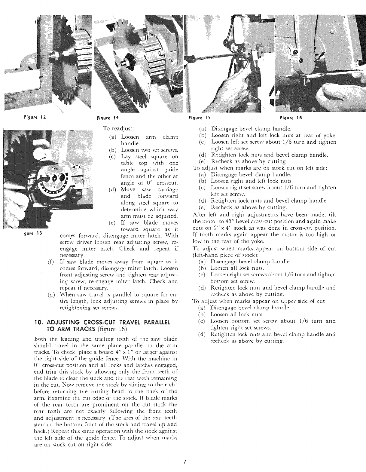
8. ADJUSTING BLADE PERPENDICULAR TO
WORK TOP (figures 12 and 13)
With the arm in cross-cut position, all latches engaged
and alI clamp handles locked place a steeI square
with one angle on the tabIe top parallel to guide strip
and the other angle against the flat of the saw blade
(place in saw blade gullets and not against teeth
because of tooth set). If blade is not flat against
squarej adjust as follows:
(a) Remove name plate by removing two screws.
(b) Loosen two outside socket head screws.
(c) Loosen bevel clamp handle.
(d) Tilt motor until blade is flat against the square
and again lock (very firmly) socket head
screws. Replace name plate,
NOTE: In some cases it will be found necessary
to also Ioosen center cap screw in order to adjust
motor.
9. ADJUSTING CROSS CUT TRAVEL WITH
GUIDE FENCE (figures 14 and 15)
With the miter latch engaged and arm clamp handle
locked, place a wide board (l"x 12" if available)
against the guide strip. Cross-cut this board with a
set tooth blade. Check cut with a steel square_ If
cut is not square, the arm is out of alignment with
the guide fence.
IO
(g)
To readjust:
(a) Loosen arm clamp
handle.
(b) Loosen two set screws.
(c) Lay steel square on
table top with one
angle against guide
fence and the other at
angle of 0 ° crosscut.
(d) Move saw carriage
and blade forward
along steel square to
determine which way
arm must be adjusted.
(e) [f saw blade moves
toward square as it
comes foc_vard, disengage miter latch. With
screw driver loosen rear adjusting screw, re-
engage miter latch. Check and repeat if
necessary.
If saw blade moves away from square as it
comes forward, disengage miter latch. Loosen
front adjusting screw and dghten rear adjust-
ing screw, re-engage miter latch. Check and
repeat if necessa W.
When saw travel ix paralle! to square for en-
tire length, lock adjusting screws in place by
retightcning set screws.
10. ADJUSTING CROSS-CUT TRAVEL PARALLEL
TO ARM TRACKS (fig-ure I6)
Both the leading and trailing teeth of the saw blade
should travel in the same plane parallel to the arm
tracks. To check, place a board 4" x 1" or larger against
the right side of the guide fence. With the machine in
0 ° cross-cut position and all locks and latches engaged,
end trim this stock by allowing only the front teeth of
the blade to clear the stock and the rear teeth remaining
in thc cut. Now remove the stock by s[idlng to the right
before returning the cutting head to the baek of the
arm. Examine the cut edge of the stock. If blade marks
of' the rear teeth are prominent on the cut stock d_e
rear teeth are not exactly following the front teeth
and adjustment is necessary. (The arcs of the rear teeth
start at the bottom front o[' the stock and travel up and
baek.} Repea_ this same operation whh the stock against
the left side of the guide fence. _l)J adjust when marks
are on stock cut on right side:
Sure _ 3
(a) Disengage bevel clamp handle,
(b) Loosen right attd left lock nuts at rear of yoke,
(c) Loosen left set screw about 1/6 turn and tighten
right set screw,
(d) Ret,ighten lock nuts and bevel damp handle.
(e) Recheck as above by cutting,
To adjust when marks are on stock cut on [eft side:
(a) Discngagc bevel clamp handle.
(b) Loosen right and left fock nuts,
(c) Looscn right set screw about 1/6 turn and tighten
left set screw,
(d) Retighten lock nuts and bevel damp handle.
(e) Recheck as above by cutting,
After left and rlght adjustments have been made, tilt
the motor to 45 _ bevel cross-cut position and again make
cuts on 2"x 4" stock as was done in cross-cut position.
If tooth marks again appear the motor is too high or
low in the rear of the yoke.
To adjust when marks appear on bottom side of cut
(left-hand piece of stock):
Disengage bevel clamp handle.
(b) Loosen all lock nuts,
(c) Loosen right set screws about i/6 turn and tighten
bottom set screw,
(d) Redghten lock nuts and bevel clamp handle and
recheck as above by cutting.
To adjust when marks appear on upper side of cut:
(a) Disengage Bevel clamp handle,
(b) Loosen all lock nuts.
(c) Loosen bottom set screw about l/6 turn and
tighten right set screws.
(d) Retighten lock nuts and bevel clamp handle and
recheck as above by cutting,
RULES FOR SAFER OPERATION
OF 8TA TIONARY POWER TOOLS
1. KEEP GUARDS IN PLACE and in working order.
2. REMOVE ADJUSTING KEYS AND WRENCHES. Form habit of
checking to see that keys and adjusting wrenches are removed
from tool before turning it on.
3. KEEP WORK AREA CLEAN. Cluttered areas and benches invite
accidents.
4. DON'T USE IN DANGEROUS ENVIRONMENT. Don't use power
tools in damp or wet locations, or expose them to rain. Keep
work area well lighted.
5. KEEP CHILDREN AWAY. All vistors should be kept a safe
distance from work area.
6. MAKE WORKSHOP KID PROOF with padlocks, master switches,
or by removing starter keys.
7. DON'T FORCE TOOL It will do the job better and be safer at the
rate for which it was designed.
8. USE RIGHT TOOL Don't force tool or attachment to do a job for
which it was not designed.
9. WEAR PROPER APPAREL No loose clothing, gloves neckties,
rings, bracelets, or other jewelry to get caught m moving parts.
Nonslip footwear is recommended. Wear protective hair cover-
ing to contain long hair.
10. ALWAYS USE SAFETY GLASSES. Also use face or dust mask if
cutting operation is dusty. Everyday eyeglasses only have
impact resistant lenses, they are NOT safety glasses.
11. SECURE WORK. Use clamps or vise to hold work when practical.
It's safer than using your hand and it frees both hands to
operate tool.
12. DON'T OVERREACH. Keep proper footing and balance at all
times.
13. MAINTAIN TOOLS WITH CARE. Keep tools sharp and clean for
best and safest performance. Follow instructions for lubricating
and changing accessories.
14. DISCONNECT TOOLS before servicing; when changing
accessories such as blades, bits, cutters, etc.
15. REDUCE THE RISK OF UNINTENTIONAL STARTING. Make
sure switch is in off position before plugging in.
16. USE RECOMMENDED ACCESSORIES. Consult your Sears store
for recommended accessories. The use of improper accessories
may cause risk of injury to persons.
17. NEVER STAND ON TOOL Serious inju_ could occur if the tool
is tipped or if the cutting tool is unintenhonally contacted.
18. CHECK DAMAGED PARTS. Before further use of the tool, a
uard or other part that is damaged should be carefull xchecked
determine that it will operate properly and perform its intend-
ed function--check for alignment of moving parts, binding of
movingparts, breakage of parts, mounting, and any other condi-
tions that may affect =ts operation. A guard or other part that is
damaged should be properly repaired or replaced.
19. DIRECTION OF FEED. Feed work into a blade or cutter against
the direction of rotation of the blade or cutter only.
20. NEVER LEAVE TOOL RUNNING UNATI'ENDED. TURN POWER
OFF. Don't leave tool until it comes to a complete stop.
21. ONE OPERATOR ONLY. The same person who pulls saw should
position the work.
DIRECTIONS FOR REMOVING ARBOR NUT
(Figure 2, Page 3)
1. Fit 5/16 WAllen Wrench into front end of motor shaft. (This is a
holding wrench only.)
2. Fit large wrench on arbor nut as nearly parallel to first wrench as
possible.
3. While holding first wrench stationary with right hand, use
downward pressure of left hand on second wrench and nut will
loosen.
MAINTENANCE AND OPERATION
1. DO--Be sure blade rotates clockwise when facing arbor.
2. DO--Be sure all clamp handles are tight before starting any
operation. Push back to tighten. Pull to loosen.
3. DO--Be sure blade and arbor collars are clean and recessed side of
collars are against blade. Tighten arbor nut securely, using both
wrenches provided.
4. DO--Keep saw blade sharp and properly set.
5. DO--Use anti-kickback attachment on guard.
6. DO--Keep arm tracks and bearing surfaces clean and dry. Periodic
cleaning with dry cleaner is recommended.
7. DO--Periodically recheck alignment.
8. DOmRemove blade but not arbor collars and nut when using rear
shaft.
9. DOmKeep motor air slots clean and free of chips.
10. DO--Return roller head to full rear after each cross or angle cut.
Return reel is available.
1. DON'T--Attempt to operate on anything but designated voltage.
2. DON'T---Operate unless all clamp handles are tight.
3. DON'T--Use blades of larger diameter than recommended.
4. DON'T--Remove anti-kickback from guard. Adjust it to just clear
the workpiece when crosscutting,
5. DON'T--Rip from wrong direction--observe caution tag on guard.
6. DON'T--Oil or grease arm tracks or motor.
7. DON'T--Wedge anything against fan to hold motor shaft.
8. DON'T--Subject table top to variable humidity conditions (keep
away from damp place.)
9. DON'T--Force cutting action. Stalling or partial stalling of motor
can cause major damage to motor winding.
10. DON'T--Remove saw blade guard when boring.
11. DON'T--Remove arbor collars and nut when using rear shaft.
12. DON'T--Remove ground prong from plug. Never operate saw
unless it is properly grounded.
13. DONW--Remove small scraps from table with fingers.
The lower blade guard covers the side of the teeth when the blade is
behind the fence. READ THE FOLLOWING PRECAUTIONS.
CAUTIONS TO FOLLOW WHEN USING LOWER
GUARD:
1. The lower blade guard will provide additional protection from
contact with the side of the blade--BUT NOT FROM CONTACT
WITH THE FRONT OR REAR OF THE BLADE.
When the lower guard touches the fence or material being cut, it will
rise up over the material--thus exposing the blade teeth. Be careful,
keep your hands out of the line of cut!
2. Lower blade guards may become caught in prior kerfs in the fence or
table. Replace guide fence frequently.
3. Short cut-off pieces of wood may become caught between the lower
guard and the blade. If this happens, shut off power; wait until
blade stops before removal of piece.
4. The lower blade guards effectiveness is limited in bevel operations.
It may have to be raised out of the way when setting bevel angle to
prevent bending. BE SURE THAT POWER IS OFF AND BLADE
IS COMPLETELY STOPPED BEFORE MAKING ANY AD-
JUSTMENT.
5. Catching the lower guard in saw kerfs when changing the saw set-up
can be avoided by elevating the saw until the bottom of the guard
clears the fence.
6. When ripping narrow strips, the lower guard may have to be raised
to rest on top of the fence. Be sure to use a pusher stick to feed the
work.
7. Do not use the lower guard with any accessory other than the correct
size saw blade.
8. To summarize, when in doubt about whether to use the lower guard,
and when practical, make a "dry run" with power off to determine
if it is a help or hindrance.
MOTOR OVERLOAD PROTECTION
Your single-phase Saw Motor is equipped with a manuai-reset type
overload protector. If the protector "trips" and stops the motor, take the
following steps:
1. Press the saw "OFF" switch button and allow the motor to cool.
2. After motor has cooled, the overload protector may be reset by
firmly pressing the red reset button located on the rear of the
motor connection box. If you do not hear an audible "click",
the motor must be allowed to cool further before attempting the
reset.
3. After the reset is accomplished, the saw may be started by
pushing the "ON" button.
°OPERATING INSTRUCTIONS °
Observe and comply with the warning labels on the saw.
WARNING
FOR YOUR OWN SAFETY READ INSTRUCTION
MANUAL BEFORE OPERATING SAW
1. Wear eye protection.
2. Keep hands out of path of saw blade.
3. Return carriage to full rear position after each crosscut type of
operation.
4. Know how to reduce risk of kickback.
5. Use pusher board for narrow work.
6. Do not perform any operation freehand.
7. Never reach around moving saw blade.
8. Shut off power before clearing a stall or jam.
9. Make noadjustments until tool has stopped.
DANGER
TO AVOID INJURY DO
NOT FEED MATERIAL
INTO CUTTING TOOL
FROM THIS END
Use common sense, think all operatio_ threugh before _,arting,
and be alert.
Review the "Rules For Safer Operation of Stationary Power
Tools" and "Maintenance and Operation" sections. (See index)
Keep saw in good adjustment and alignment; use only sharp,
free-cutting tools and accessories that were designed for your
machine. These precautions will help reduce the possibility of
jam-ups or kickbacks.
Never perform any operation "free hand" (i.e. supporting the
workpiece by hand alone). The workpiece must always be solidly
supported or guided by the fence or supporting jig or fixture to
prevent any unexpected movement.
If the sawblade or cutter becomes stalled or lower guard
becomes jammed- Turn off po_r immediately. Never attempt to
free a jam up without first turning power off. Remove workpiece
and re-check machine alignment. Adjust as necessary.
DANGER Coasting cutting tools can be dangerous - apply the
brake immediately on manual braking units to stop the tool as
soon as the switch is turned off.
The torque developed during manual or automatic braking may
loosen the blade retaining nut, therefore the arbor nut should be
checked periodically and tightened if necessary.
Never cycle the tool "on" and "off" rapidly, as forces can be pro-
duced which will loosen the arbor nut.
If the arbor nut should ever loosen, allow the blade to come to a
complete stop and re-tighten the arbor nut securely, but not
excessively, using both wrenches provided.
Read through and study the pictorial operating ir_'uctto_ which
follow for further instructions before using your new Craftsman
Radial Arm Saw.
Kickbacks can occur when the workpiece binds between the saw
blade and the fence during a ripping type operation. Such action
could cause the workpiece to be ejected from the machine and
thrown violently back towards the operator.
Never stand, or permit someone else to stand in line with the
work being ripped due to possible kickbacks.
The anti-kickback fingers must be kept sharp, free moving and
correctly adjusted to insure proper operation.
Use extra care when ripping material that is twisted or bowed
which can rock on the saw table and cause pinching or binding.
Place the wood on the table in such a manner as to minimize
rocking.
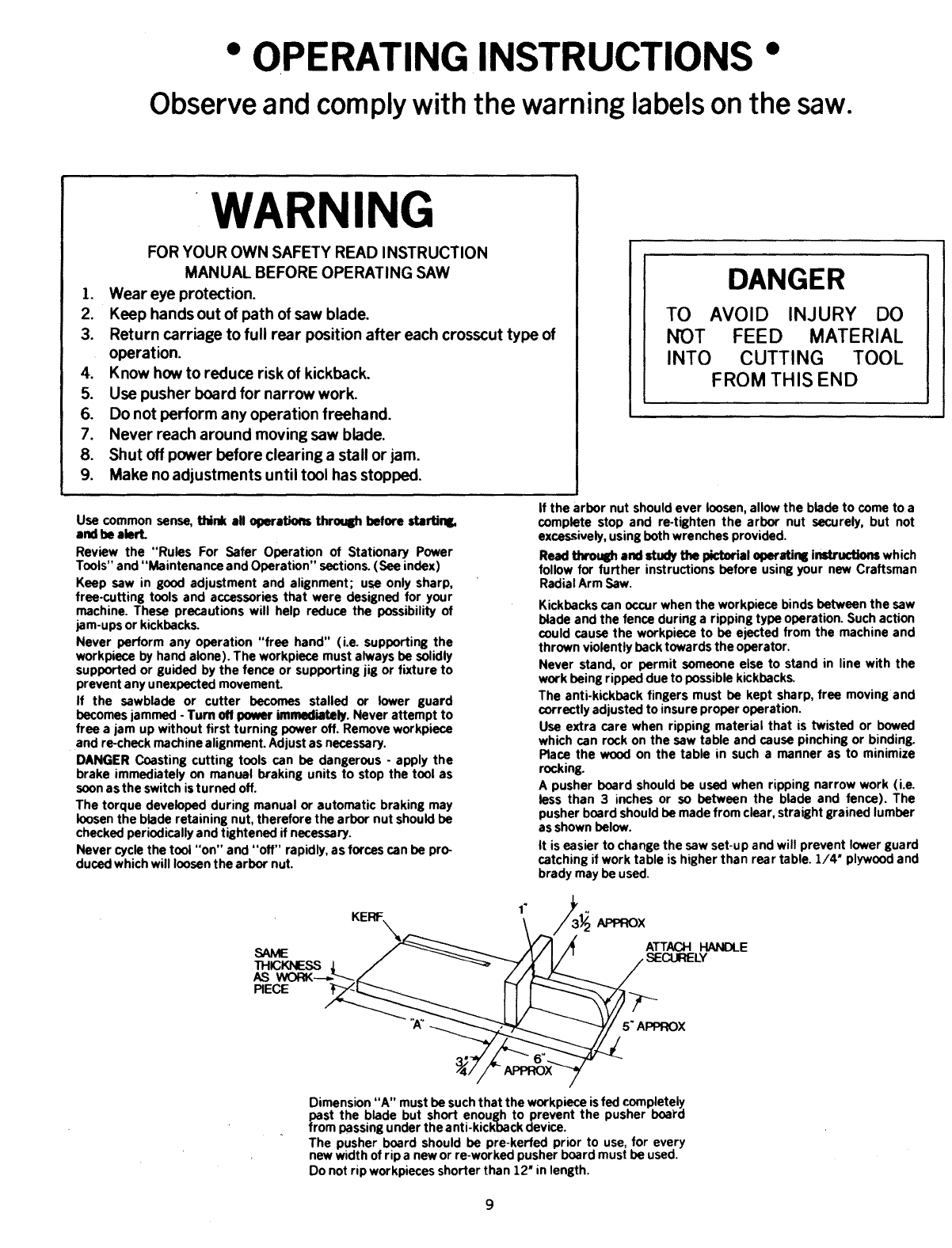
A pusher board should be used when ripping narrow work (i.e.
less than 3 inches or so between the blade and fence). The
pusher board should be made from clear, straight grained lumber
as shown below.
It is easier to change the saw set-up and will prevent lower guard
catching if work table is higher than rear table. 1/4" plywood and
brady may be used.
""\
.... _ f/I /1' ATTACHHAi'i:ILE
THIC_SS ' /_"_----_'.....-JVI/',, SECURELY
-
Dimension "A" must be such that the workpiece is fed completely
past the blade but short enough to prevent the pusher boa_'d
from passing under the anti-kickback device.
The pusher board should be pre-kerfed prior to use, for every
new width of rip a new or re-worked pusher board must be used.
Do not rip workpieces shorter than 12" in length.
9
OPERATI NG iNSTRUCTiONS
CAUTION
For purposQ._ of clarity, €he lower guard is ornVtt'ed
fr,_rn _he photographs inside 'l'hts manual. However.
ALL ou'_s mus_ be mode w_"th both _'he upper and
lower guards in place.
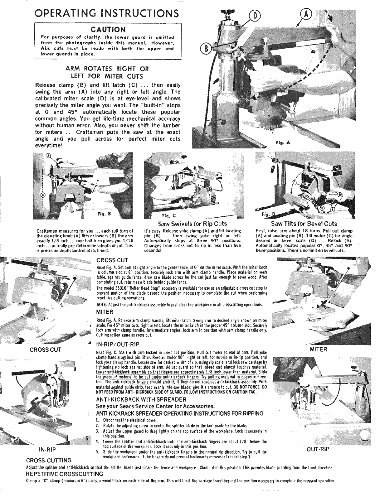
ARM ROTATES RIGHT OR
LEFT FOR MITER CUTS
Release clamp (B) and lift latch (C) ... then easily
swing the arm (A) into any right or left angle. The
calibrated miter scale (D) is at eye-level and shows
precisely the miter angle you want. The "built-in" stops
at 0and 45 ° automatically locate these popular
common angles. You get life-time mechanical accuracy
without human error. Also, you never shift the lumber
for miters ... Craftsman puts the saw at the exact
angle and you pull across for perfect miter cuts
everytimet
Craftsman measures Jor you ,,. eadl lull turn o!
the elevating knob (A) tiffs or lowers (B) the arrn
exactiy 1/8 inch ,,, one haft turn gives you 1/16
inch.. •actually pro+determines depth o( cut+ This
is predsion depth centrol at its finest.
F;g, C
Saw Swivels for Rip Cuts
It's easy. Retease yoke clamp (A) and tilt locating
pin (B) ,.. then swing yoke right or letL
Automatically stops at three 90 '= positions.
Changes trorn cress cut to rip in less than five
seoonds!
Saw Tilts for Bevel Cuts
FirsL raise arm about 18 turns, Pul! out clamp
(A) and Iocaiing pin (B), Tilt motor (C) for angle
desired on bevel scale (D) .., Releck (A),
Automaticallylocatespopular 0% 45 '_and 90_'
bevel positions. There's no limit on bevel cuts,
CROSS CUT
Read Fig.A.Setarm atrightangletotheguidefence,at0° on themiterscaie_Withthemiterla_h
incolumn slatat0° position,securel)'lockarrn with arm clamp handle,Placematerialon work
_ble,againstgoldefence,drawsaw bladeacrossbr the culiustfarenoughtoseYerw_d. After
completingcuf_returnsaw bladebehindguidefence,
The model 35010 "Roller Head Stop"accessoryisevadablefar useasanadjus_blec_o.,sscutstopto
preventme,be of thebladebeyondthepositionnecossaryto completethecut when per(ermine,
_epetitivecuttingoperations,
NOTE:Adjust the anti.kickback assembly to just clan{ t_e wafkpiece in all crosscutting operations.
MITER
ReadFig._ Releasearmclamphandle,liftmiler latch.Swinga_ tod_iredangleshownonmiter
scale.Fo_45° mitercut_4rightorleft,locatethemiterlatchintheproper45°c(Rumnslot.Securely
bck armwithclamphandle.Intermediateangles:10cAarmin positionwith armclamphandleonly,
Cuttingeoliansameascro_ cut.
IN-RIP!OUT-RIP
CROSS CUT MITER
Read Fig,C, Stad witharm l_ked in cresso,tposition,Pulloutmeter toend ofa{m,Pullyoke
clamp handle against pin litter. Revolve mote( 90°, light or left, for out=rip or in.rip position, and
locky_e clamp handle,Locatesaw fordesiredwidlho(rip,_singripscale,and Tooksaw carriageby
tightening rip lock against side el arm. Adjust guard so thal intend end almost touches material.
Loweranti-kickbackassembl__ a___x_ate_ 1/8 inchlowerthan material,Siid_e
thej_ieceof malarialtobe cutu_de_ anti,k'_k_b_ackfin_.T_TR pul!ingmaterial._i_J!_tedi_ec.
tide.The antiokiekb__no_ anti-.kickbackassem_i_.With
materiala_ainstg_idestrip,feede_enlyintosaw blade;_iveita chancetocut.O0 NOT FORCE DO
NOT FEEDFROM ANTi-KICKBA(7,_SIDEOF GUARD. _LLOW I_STRUCTIONSON ¢..,J_,UTIONTAG.
ANTI-KICKBACK WITH SPREADER.
See your Sears Service Center tot Accessories.
ANTI-KICKBACK SPREADEROPERATINGiNSTRUCTiONS FORRiPPiNG
LDisconnectlheelectri_l pOwer.
2, Rotatetheadiustingscrewtocenterthesplitterbladeintheker!made bytheblade,
3, Adiusttheuppe_guard to draglightly on lhetopsurfaceof _hewofkpiece.Loskit secureb'in
ibis position.
4, Lowerthe splilterand anti-kickbackuntiltheanti.kickbackfin_ersare aboutLi_" below lhe
topsudaceof theworkplace.Lockitsecurelyin this position.
5. Slide the workplace under the anti-kicWbackfingers in the no_mal rip di{ecUon, Try to pult {he
workplacebackwards. If the _ingers do not preventbackwards mwemen{ repeat step 3.
IN-RIP
CROSS-CUTTING
OUT-RiP
Adjustthesplitterand anti,kickbackso lhatthesplitterbladejestclearsthefenceand workpiece,Clamp ifinthisposition.Thisp(ovidosbladeguardingfrom thefronldirection.
REPETITIVE CROSSCUTTING
Clamp a"¢" clamp (minimum 6") using a wood b_k on each side ot the a_m,Th(swill limit the _rria_e tza_el beyond the positionnecessaryto complete the crosscut operation.
CAUTION
•For purposes of clarify, _the Lower guard is om|t_ted from _he
photographs inside tth|s manual However, ALL eu_s mus_t be
made wi_h bo_h _he upper and lower guards in place.
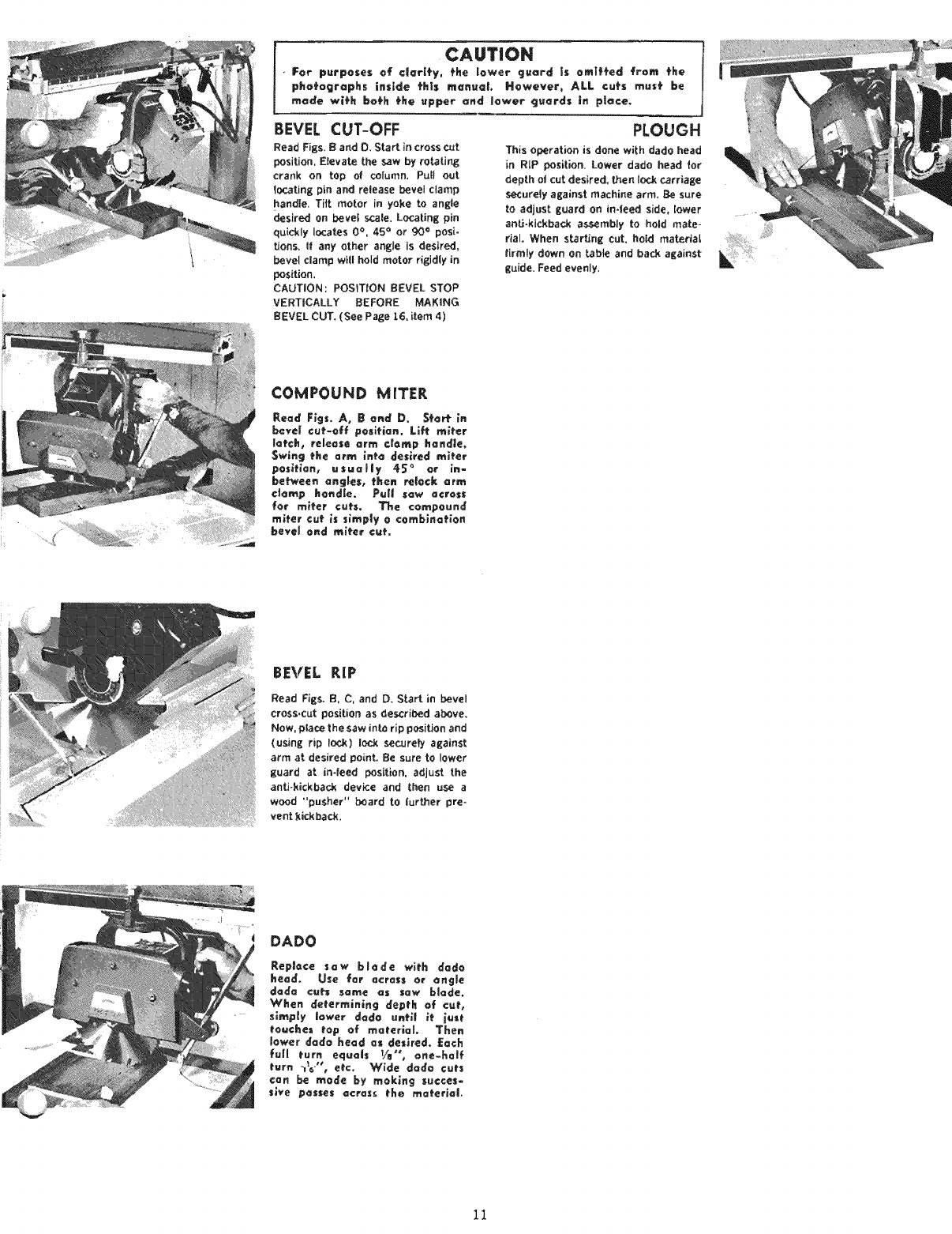
EEVEL CUT-OFF
Read Figs. Band D, Start in cross Cut
position, Elevate the saw by routing
crank on top of column, Puff out
_ocating pin and release bevel clamp
handle. Titt motor in yoke to angle
desired on beve_ scale. Locating pin
quickly locates 0°, 45 °or 90 = posi-
tions, If any other angle is desired,
bevel clamp wi!l hold motor rigidly in
position,
CAUTION: POSITION BEVEL STOP
VERTICALLY BEFORE MAKING
BEVEL CUT, (See Page _.6, item 4)
PLOUGH
This operation is done with dado head
in RtP position. Lower dado head tot
depth o| cut desired, then lo_..kcarriage
_cureiy against machine arm, Be sure
to adjust guard on in-feed side, lower
artS-kickback a_mbiy to hold mate-
riaL When sf_rt_ng cut, hold material
tirmty down on _ble and back against
guide, Feed evenly,
COMPOUND MITER
Read Figs, Ao g end D. $_or_ in
hovel cut-off pesiHan. Li_ roller
lot€h, rele=se arm €|omp handle.
Swing the arm into desired miter
posiHan, usually 45 °or in-
be_een angles, then retook _rrn
e|amp bond[c, Pu{| saw across
for miter curs. The compound
roller cut _s slmp|y o comb_naHon
bevel end mlter ¢u_.
BEVEL RiP
Read Figs. B, C, and D. S_rt in bevel
Cross.cut position as described above.
Now, place the saw into rip position and
(using rip l_ck) I_ t_oJreiy against
arm at desiredpoint.Be sure to lower
guard at in-local position, adjust the
anti-kickback devk:e and [hen use a
wood "pusher" board to _urtber pre-
vent kickback.
DADO
Replace saw blade wltE dado
kead. Use for across or angle
doda co_ same as saw bh=de.
When defermining deptth of cu_',,
s_mp|y lower dodo unH| }f j=sf
touche_ top of maferlal, Then
lower dodo heed as des_re_. Each
full turn equals Va", one-half
_'urn "_="', etc. Wide dodo Cuts
can be mode by rnoklng succes-
sive posses _crass the ma_erio_.
11
CA@T_ON
For purposesof cfari_y, fhe lower guard is om_ffed from
fhe phofographs inside fhls manual However, ALL curs
mus÷be made w_fh bofh fhe upper and !ower guards in
place.
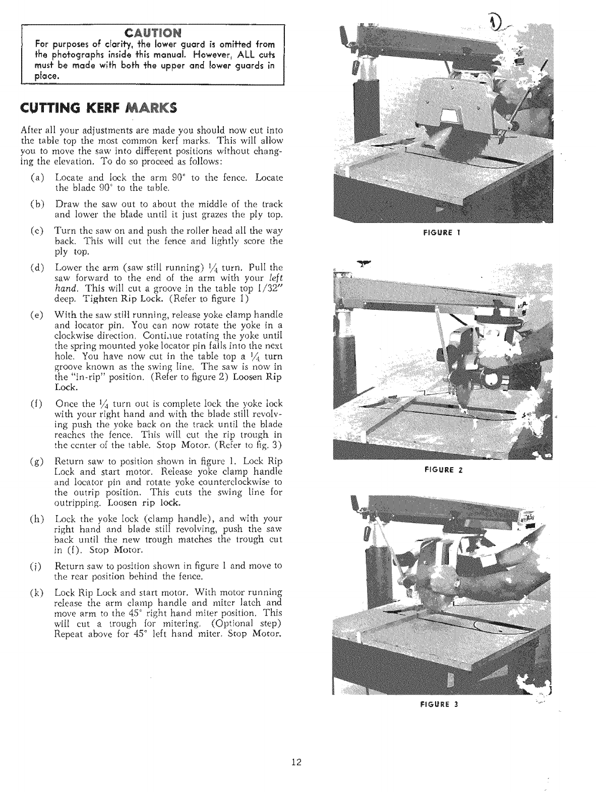
CUTTING KERF MARKS
After all your adjustments are made you should now cut into
the table top the most common kerr marks. This will allow
you to move the saw into different positions without ehang-
ing the eIevation. To do so proceed as follows:
(a) Locate and lock the arm 90° to the fence. Locate
the blade 90° to the table,
(by
(c)
(d)
(e)
Draw the saw out to about the middle of the track
and lower the blade until it just grazes the ply top.
Turn the saw on and push the roller head all the way
back, This will cut the fence and lightly score the
ply top.
Lower the arm (saw still running) 1/{i turn, PutI the
saw forward to the end of the arm with your left
hand. This will cut a groove in the table top 1/32"
deep. Tighten Rip Lock. (Refer to figure I)
With. the say/still running, release yoke clamp handle
and locator pin. You can now rotate the yoke in a
clockwise direction, Conti.me rotating the yoke until
the spring mounted yoke locator pin fails into the next
hole. You have now cut in the tabIe top a 1_ turn
groove known as the swing Iine. The saw is now in
the "in-rip" position. (Refer to figure 2) Loosen Rip
Lock.
(f)
(g)
(h)
(k)
Once the 1/_ turn out is complete loek the yoke lock
with your right hand and with the blade still revoIv-
ing push the yoke back on the track until the blade
reaches the fence. This will cut the rip trough in
the center of the table. Stop Motor. (Refer to fig. 3)
Return saw to position shown in figure 1. Lock Rip
Lock and start motor, ReIease yoke clamp handle
and locator pin and rotate yoke counterclockv,,ise to
the outrip position. This cuts the swing line for
outripping. Loosen rip lock.
Lock the yoke Iock (clamp handle), and with your
right hand and blade still revolving, push the saw
back until the new trough matches the trough cut
in (f). Stop Motor.
Return saw to position shown in figure I and move to
the rear position behind the fence.
Lock Rip Lock and start motor. With motor running
reIease the arm clamp handle and miter latch and
move arm to the 45 ° right hand miter position, This
will cut a trough for mitering, (Optional step)
Repeat above for 45" left hand miter. Stop Motor.
FIGURE I
FIGURE 2
FIGURE 3
12
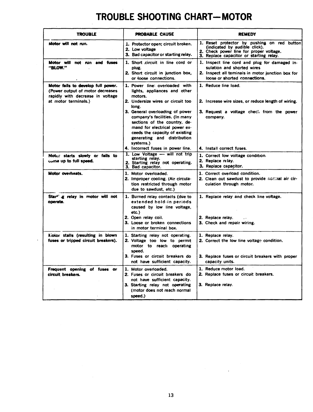
TROUBLE SHOOTING CHART--MOTOR
TROUBLE PROBABLE CAUSE
Motor will not run. 1.
Motor will not run and fuses
"BLOW."
Protector open; circuit broken.
2. Low voltage
3. Bad capacitor or starting relay.
1. Short ,circuit in line cord or
plug.
2. Short circuit in junction box,
or loose connections.
Motor fails to develop full power. 1.
(Power output of motor decreases
rapidly with decrease in voltage
at motor terminals.) i2.
3.
4.
Motor starts slowly or fails to 1,
_me up to full speed. 2.
3.
Motor overheats. 1.
2.
Star*: 4g relay in motor will not 11
operate.
2.
3.
I_ stalls (resulting in blown 1.
fuses or tripped circuit breakers). 2.
3.
Frequent opening of fuses or 1.
circuit breakers. 2.
3.
Power line: overloaded with
lights, appliances and other
motors.
Undersize wires or circuit too
long.
General overloading of power
company's facilities. (In many
sections of the country, de-
mand for electrical power ex-
coeds the capacity of existing
generating and distribution
systems.)
Incorrect fuses in power line.
Low Voltage -- will not trip
starting relay.
Starting relay not operating.
Bad capacitor.
Motor overloaded.
Improper cooling. (Air circula-
tion restricted through motor
due to sawdust, etc.)
Burned relay contacts (due to
extended hold-in periods
caused by low line voltage.
etc.)
Open relay coil.
Loose or broken connections
in motor terminal box.
Starting relay not operating.
Voltage too low to permit
motor to reach operating
speed.
Fuses or circuit breakers do
not have sufficient capacity.
Motor overloaded,
Fuses or circuit breakers do
not have sufficient capacity.
Starting relay not operating
(motor does not reach normal
speed.)
REMEDY
1. Reset protector by pushing on red button
(indicated by audible click).
2. Check power line for proper voltage.
3. Replace capacitor or starting relay.
1. Inspect line cord and plug for damaged in-
sulation and shorted wires
2. Inspect all teminals in motor junction box for
loose or shorted connections.
1. Reduce line load.
2. Increase wire sizes, or reduce length of wiring.
3. Request a voltage chec:, from the power
company.
4. Install correct fuses.
1. Correct low voltage conditlon.
2. Replace relay.
3. Replace capacitor.
1. Correct overload condition.
2. Clean out sawdust to provide no;:.lal air cir-
culation through motor.
1. Replace relay and check line voltage.
2. Replace relay. .o
3. Check and repair wiring.
1. Replace relay.
2. Correct the low line voltag_ condition.
3. Replace fuses or circuit breakers with proper
capacity units.
1. Reduce motor load.
2. Replace fuses or circuit breakers.
3. Replace relay.
13
4G
40
/
5!
23
t
44
/
\
2
/
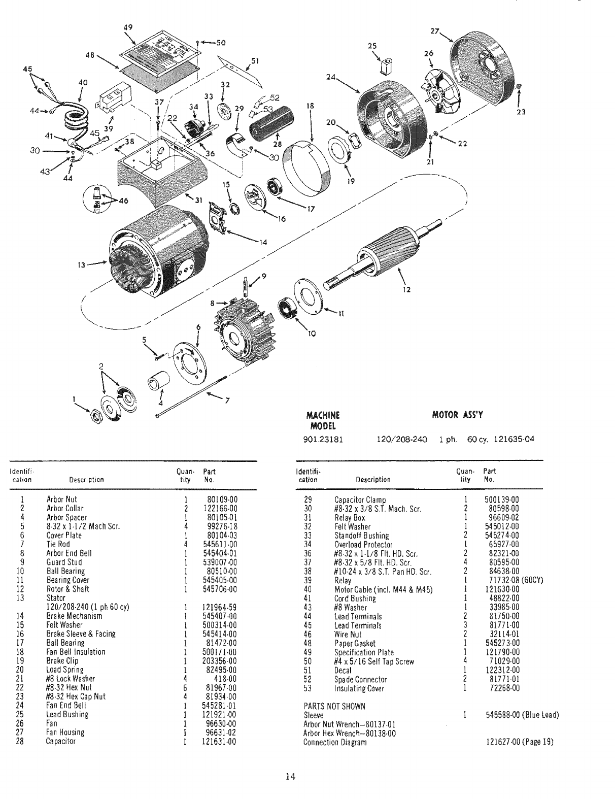
901.23181 120/208-24-0 1 ph, 60cy. 121635-04
Identifi- Quan- Part
caliph Description tit'/ No.
1 ArborNut
2 ArborCotlar
4 ArborSpacer
5 8-32x 14/2 MathScr.
6 CoverPlate
7 TieRod
8 ArborEndBell
9 GuardStud
10 BailBearing
11 BearingCover
12 Rotor& Shaft
13 Stator
120/208.240(1 ph60cy)
14 BrakeMechanism
15 FeltWasher
]6 BrakeSleeve& Facing
17 BaliBearing
18 FanBellInsulation
19 BrakeCtip
20 LoadSpring
2[ #8LockWasher
22 #8-32HexNut
23 #8.32HexCapNut
24 FanEndBell
25 LeadBushing
26 Fan
27 FanHousing
28 Capacitor
1
2
1
4
1
4
1
!
1
1
1
I
1
1
1
1
1
i
I
4
6
4
I
I
I
I
1
80[09.00
122166,00
80105-01
99276-I8
80104,03
545611,00
545404-01
539007a0
80510.00
54540540
545706.00
121964-59
545407-00
500314-00
545414.00
8147240
500171-00
203356.00
82495.00
418-00
81967-00
8[934.00
545281,01
121921,00
96630-00
96631-02
12163140
Identifi- Q_an- Pad
cation Description Iity fro.
29 CapacitorClamp [ 500139,00
30 #8.32x3/8 &T, Mach,Scr, 2 80598-00
31 RelayBox 1 96609.02
32 FeltWasher 1 545012.00
33 StandoffBushing 2 545274,00
34 OverloadProtector [ 65927.00
36 #8-32x 1-1/8 Fit.HD.Scr, 2 82321-00
37 #8,32x5/8 Fit,HD.Scr. 4 80595-00
38 #10-24x3/8 S,T.PanHD.Scr. 2 84638-00
39 Relay 1 7[732-08(60CY)
40 MotorCable(incl, M44& M45) 1 121630-00
41 CordBushing 1 48822,00
43 #8Washer 1 33985-00
44 LeadTerminals 2 81750-00
45 LeadferminaIs 3 81771-00
46 WireNut 2 32114-01
48 PaperGasket 1 545273.00
49 SpecificationPlate [121790-00
50 #4 x5/16 SelfTapScrew 4 7[029,00
51 Deca! i 122312-00
52 SpadeConnector 2 81771-0l
53 InsulatingCover [ 72268,00
PARTSNOTSHOWN
Sleeve I 545588-00(BlueLead)
ArborNutWrench-80137-01
ArborHexWrench-80138-O0
ConnectionDiagram 121627.00(Page19)
t4
40
i
29 37
30 i
&
J
38
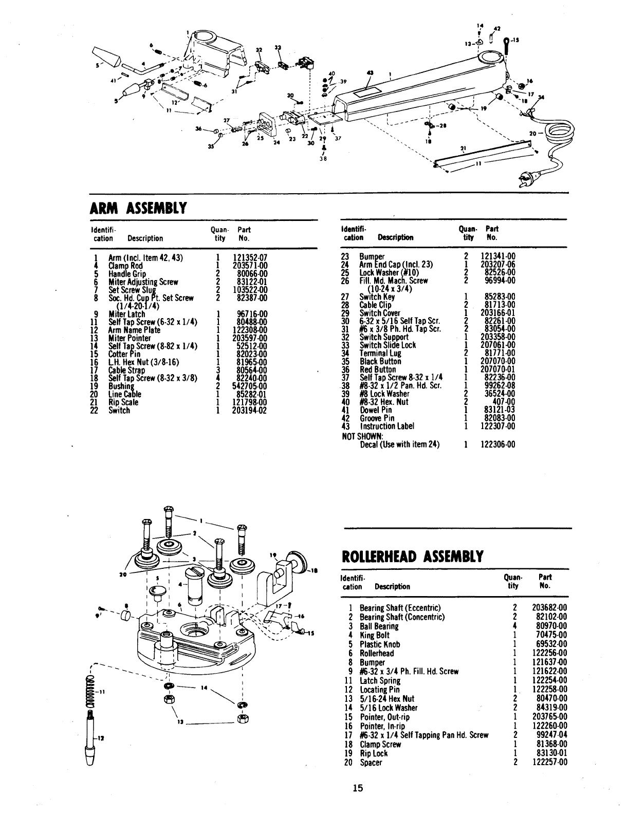
ARM ASSEMBLY
Identifi+ Quan- Part
cation Description tity No.
lArm(Incl.Item42,43) l 121352-07
4 ClampRod l203571.00
5 HandleGrip 2 80066-00
6 MiterAdjustingScrew 2 83122-01
7 SetScrewSlug 2 103522.00
8 Soc.Hd.CupPt.SetScrew 2 82387.00
•.(1/.4.2o.1/4)
9 MiterLatcn l 96716.00
11 SelfTapScrew(6-32 x1/4) 1 80488-00
12 ArmNamePlate 1 122308.00
13 MiterPointer ] 203597.00
14 SelfTapScrew(8-82x 1/4) ] 52512-00
15 CotterPin 1 82023-00
16 LH. HexNut(3/8-16) 181965-00
17 CableStrap 3 80564-00
18 SelfTapScrew(8-32x 3/8) 4 82240.00
19 Bushing 2 542705-00
20 LineCable 1 85282-01
21 RipScale 1 121798.00
22 Switch ] 203194.02
Identifi- Quan. Part
cation Description tity No.
23 Bumper 2 121341-00
24 ArmEndCap(incl.23) 1203207.06
25 LockWasher(P]O) 2 82526-00
26 Fill.Md.Mach.Screw 2 96994-00
^(10-24x3/4)
27 :_wltchKey 185283-00
28 CableClip 2 81713+00
29 SwitchCover 1203166-01
30 6-32x 5/] 6 SelfTapScr. 2 8226]-00
3] #6x 3/8 Ph.H_ TapScr. 2 83054-00
32 SwitchSupport 1 203358.00
33 SwitchSlideLock 1 207061.00
34 TerminalLug 2 81771-00
35 BlackButton 1 207070-00
36 RedButton 1 207070-01
37 SelfTapScrew8-32x 1/4 1 82236.00
38 #8-32x1/2 Pan.Hd.SCr. 1 99262.08
39 #8 LockWasher 2 36524.00
40 #8-32Hex.Nut 2 407.00
4] DowelPin ] 8312].03
42 GroovePin 1 82083-00
43 InstructionLabel 1 122307.00
NOTSHOWN:
Decal(Usewithitem24) ] 122306-00
_CD "--- m4
--I1 I
ROLLERHEADASSEMBLY
Identifi- Quan- Part
cation DescdpUon tity No.
1BearingShaft(Eccentric) 2 203682-00
2BearingShaft(Concentric) 2 82102-00
3 BallBearing 4 80970.00
4 KingBolt 1 70475.00
5 PlasticKnob 1 69532.00
6 Rollerhead 1 122256.00
8 Bumper 1 121637.00
9#6-32x 3/4 Ph.Fill.Hd.Screw 1 121622.00
11 LatchSpring ] 122254.00
12 LocatingPin ] 122258-00
13 5/16-24HexNut 2 80470-00
14 5/16 LockWasher 2 84319-00
15 Pointer,Out-rip 1 203765-00
16 Pointer,In-rip 1 122260-00
17 #6-32x1/4 SelfTappingPanHd.Screw 2 99247-04
18 ClampScrew 1 81368.00
19 RipLock 1 83130-01
20 Spacer 2 122257-00
15
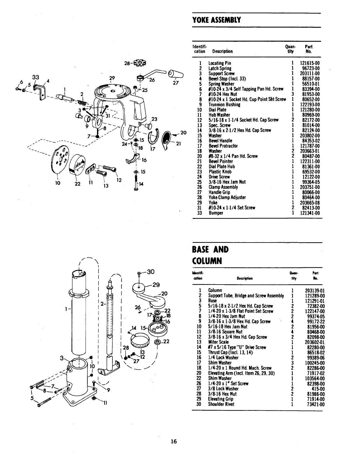
YOKEASSEMBLY
Identifi- Quan- Part
cation De_fiption tity No.
33 29
I
10 22 11 112
13
l LocatingPin ] 121615-00
2 LatchSpring ] 96723-00
3 SuppertScrew ] 203111.00
4 BevelStep(Incl.33) l 88157.00
5 SpringWasher ] 56510.01
6 #10.24x3/4 SelfTappingPanHd.Screw ] 83394-00
7#10-24HexNut 3 81953-00
8#10-24x ] SocketHd.CupPointS_tScrew ] 80652.00
9TrunnionBushing l 122193-00
10 DialPlate l 121280-00
l l HubWasher l 80969-00
12 5/16-18x l-l/4 SocketHd.CapScrew 2 82172-00
13 Spec.Screw l 81014-00
14 3/8-16 x 2-1/2 HexHd.CapScrew l 82124-00
15 Washer l 203802-00
16 BevelHandle 1 84353-02
17 BevelProtractor 1 121787-00
18 Washer 2 203663-01
20 #8-32x 1/4 PanHd.Screw 2 80487-00
21 BevelPointer 1 122311-00
22 DialPlateHub 181361-00
23 PlasticKnob 1 69532-00
24 DriveScrew 1 12122-00
25 3/8-16 HexJamNut 1 99364-05
26 ClampAssembly 1 203751-00
27 HandleGrip 1 80066-00
28 YokeClampAdjuster 1 80464-00
29 Yoke 1 203665-08
31 #10-24x1-1/4 SetScrew 2 82413-00
33 Bumper 1 121341-00
/\
BASEAND
COLUMN
Ident_- Q.on. Part
cation Descript_n tity No.
l Column 1 203139-01
2 SupportTube,BridgeandScrewAssembly l 121289.00
3 Base 1 121291-01
5 5/16-18x 2-1/2 HexHd.Capscrew 2 72382-00
7 1/4-20x 1-3/8 FlatPointSetScrew 2 122147-00
8 1/4.20HexJamNut 2 99374.05
9 3/8-16 x 1-3/8 HexHd.CapScrew 4 99172-22
lO 5/16-18HexJamNut 2 81956-00
ll 318-16SquareNut 480468-00
12 3/8-16 x 3/4 HexHd.CapScrew 2 82098-00
13 MiterScale 1 203602-01
14 #7x 5/16 Type"U"DriveScrew 1 82280-00
15 ThrustCap(Incl.13,14) 1 86518-02
16 1/4 LockWasher 2 99389-06
17 ShimWasher 3 100245-00
18 1/4-20x I RoundHd.Mach.Screw 2 82286.00
20 ElevatingArm(incl.Item26,29,30) 1 71917.02
22 ShimWasher 1 103564-00
26 1/4-20x 1"SetScrew 1 82398-00
27 3/8 LockWasher 2 415-00
28 3/8-16 HexNut 2 81986.00
29 ElevatingGrip 1 71914.00
30 ShoulderRivet 1 73421-00
16
"_13
5
8
13
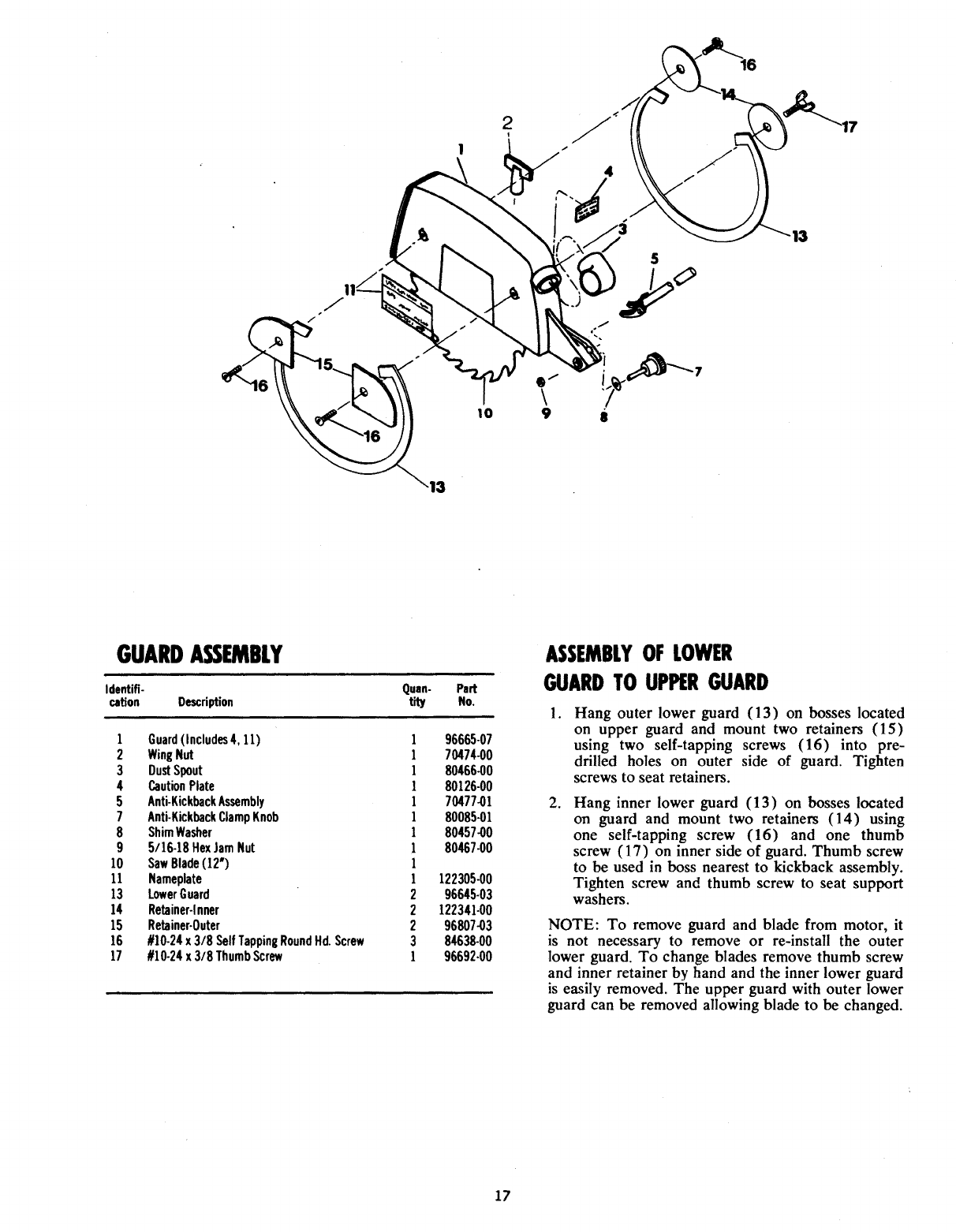
GUARDASSEMBLY
Identifi- Quan- Part
cation Description tity No.
1 Guard(Includes4, 11) 1 96665-07
2 WingNut 1 70474-00
3 DustSpout 1 80466-00
4 CautionPlate 1 80126-00
5 Anti-KickbackAssembly 170477.01
7 Anti.KickbackClampKnob 1 80085.01
8 ShimWasher 180457.00
9 5/16-18HexJamNut 1 80467-00
10 SawBlade(!2") 1
11 Nameplate 1122305-00
13 LowerGuard 2 96645-03
14 Retainer-inner 2 122341-00
15 Retainer-Outer 2 96807-03
16 ///10-24x 3/8 SelfTappiniRoundHd.Screw 3 84638-00
17 //10-24x 3/8 ThumbScrew 1 96692.00
ASSEMBLYOFLOWER
GUARDTOUPPERGUARD
.
.
Hang outer lower guard (13) on bosses located
on upper guard and mount two retainers (15)
using two self-tapping screws (16) into pre-
drilled holes on outer side of guard. Tighten
screws to seat retainers.
Hang inner lower guard (13) on bosses located
on guard and mount two retainers (14) using
one self-tapping screw (16) and one thumb
screw (17) on inner side of guard. Thumb screw
to be used in boss nearest to kickback assembly.
Tighten screw and thumb screw to seat support
washers.
NOTE: To remove guard and blade from motor, it
is not necessary to remove or re-install the outer
lower guard. To change blades remove thumb screw
and inner retainer by hand and the inner lower guard
is easily removed. The upper guard with outer lower
guard can be removed allowing blade to be changed.
17
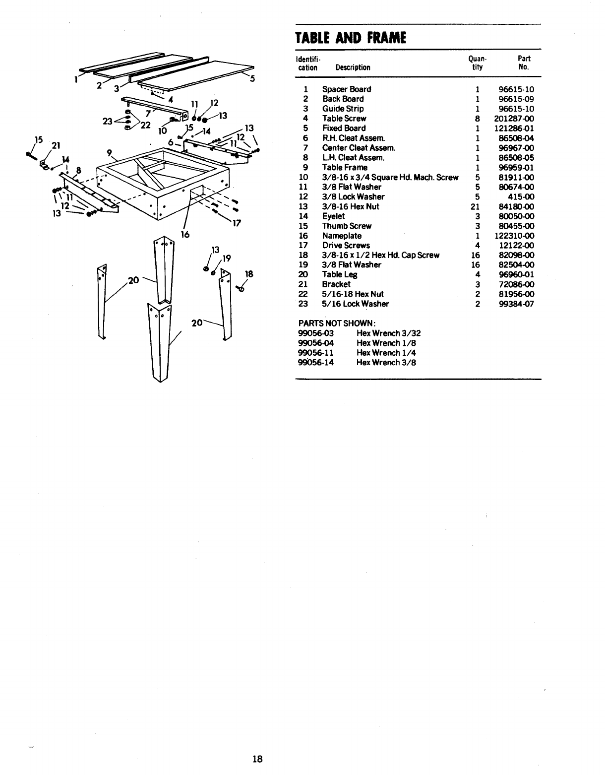
TABLEAND FRAME
Identifi. Quan. Part
cation Description tity No.
1Spacer Board 196615-10
2 Back Board 196615-09
3 Guide Strip 196615-10
4 Table Screw 8 201287-00
5 Fixed Board 1 121286-01
6 R.H. Cleat Assem. 1 86508-04
7 Center Cleat Assem. 1 96967-00
8 L.H. Cleat Assem. 1 86508-05
9 Table Frame 1 96959-01
10 3/8-16 x 3/4 Square Hd. Mac_, Screw 5 81911-00
11 3/8 Flat Washer 5 80674-00
12 3/8 Lock Washer 5 415-00
13 3/8-16 Hex Nut 21 84180-00
14 Eyelet 3 80050-00
15 Thumb Screw 3 80455-00
16 Nameplate 1 122310-00
17 Drive Screws 4 12122-00
18 3/8-16 x 1/2 Hex Hd. Cap Screw 16 82098-00
19 3/8 Flat Washer 16 82504-00
20 Table Leg 4 96960.01
21 Bracket 3 72086-00
22 5/16-18 Hex Nut 2 81956-00
23 5/16 Lock Washer 2 99384-07
PARTS NOT SHOWN:
99056-03 Hex Wrench 3/32
99056-04 Hex Wrench 1/8
99056-11 Hex Wrench 1/4
99056-14 Hex Wrench 3/8
18
oo
b
>o
0
0
RED
BLACK
I
WHITE
I
GREEN/YELLOW
BLUE _ YELLOW
ILl
Z
.J
v
-,I
19
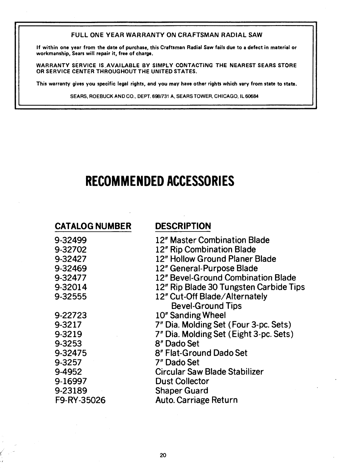
FULL ONE YEAR WARRANTY ON CRAFTSMAN RADIAL SAW
If within one year from the date of purchase, this Craftsman Radial Saw fails due to a defect in material or
workmanship, Sears will repair it, free of charge.
WARRANTY SERVICE IS.AVAILABLE BY SIMPLY CONTACTING THE NEAREST SEARS STORE
OR SERVICE CENTER THROUGHOUT THE UNITED STATES.
This warranty gives you specific legal rights, and you may have other rights which vary from state to state.
SEARS, ROEBUCK AND CO., DEPT. 698/731 A, SEARS TOWER, CHICAGO, IL 60684
IHHII IIIIIII1[
RECOMMENDEDACCESSORIES
CATALOG NUMBER
9-32499
9-32702
9-32427
9-32469
9-32477
9-32014
9-32555
9-22723
9-3217
9-3219
9-3253
9-32475
9-3257
9-4952
9-16997
9-23189
F9-RY-35026
DESCRIPTION
12"
12"
12"
12"
12"
12"
12"
Master Combination Blade
Rip Combination Blade
Hollow Ground Planer Blade
GeneraI-Pu rpose Blade
Bevel-Ground Combination Blade
Rip Blade 30 Tungsten Carbide Tips
Cut-Off Blade/Alternately
BeveI-G round Tips
10" Sanding Wheel
7" Dia. Molding Set (Four 3-pc. Sets)
7" Dia. Molding Set (Eight 3-pc. Sets)
8" Dado Set
8" Flat-Ground Dado Set
7" Dado Set
Circular Saw Blade Stabilizer
Dust Collector
Shaper Guard
Auto. Carriage Return
2O
iSe-rs I Sears _
;2" RADIAL ARM SAW
SERVICE Now that you he,e purchased your Radia Arm Saw,
should a need ever exist for repair Darts orservica,
simply contact any SAars Servic_ Center and most
Sears, Roebuck and Co. stores.
Be sure to orovide ai; pertinent facts when you call or
visit.
MOI;EL NO.
901.23181
The mode! number of your Rzdial Arm Saw will be found
on the Macnine Nameplate, zttached to the t_ble f-:me
IMPORTANT!--To assure product SAFETY and R_I _AblLli'Y
repairs, maintenance and adjust_--_nt _hould be performeo by
Sears ._etvice Centers or other r.,_;_,t=ed service organi;ation_.
always using C_ars replacement parts
HOW TO ._RDER
REPAIR PARTS •PART NUMBER
•MODEL NUMBER
901.23181
WHEN ORDERING REPAIR PARTS, ALWAYS GiVE
THE FOLLOWING IrJFORMATIOIV:
•P_IKT DE';CRIPTION
•NAME OF ITEM
12" Rat.'ial Arm Saw
All parts listed may be ordered frm.1 any Sears Service
Center an,; most Sears stores.
If the parts you ne_d are nc: stocked Ioc'_ll €, your nrder
will be electronically tran;mitted to ._ S,'ars Repsi;
Parts Distribution Center for ham;ring.
so;d by SEAPS, ROEBUCK P.N. ,O.,, :_,_ :g," ;L Rn6F: I J q.A.
_'0v83 3D)
Form N_. 230290 qnt_,_ J.S_-
