CRAFTSMAN Lawn, Riding Mower Rear Engine Manual L0912295
User Manual: CRAFTSMAN CRAFTSMAN Lawn, Riding Mower Rear Engine Manual CRAFTSMAN Lawn, Riding Mower Rear Engine Owner's Manual, CRAFTSMAN Lawn, Riding Mower Rear Engine installation guides
Open the PDF directly: View PDF ![]() .
.
Page Count: 100

Operator's Manual
®
Rear Engine Riding Mower with Electric Start
Model No.
107.280340 (12.5HP Briggs & Stratton Engine with 28" Mower Deck)
For answers to your questions about this
product, call:
1-800-659-5917
Sears Craftsman Help Line
5 am - 5 pm, Mon- Sat
Sears, Roebuck and Co., Hoffman Estates, IL 60179
Visit our Craftsman website: www.sears.com/craftsman
U.S.A. 7103268
Revision A
ThankYou for purchasing this quality-built Craftsman product. We're pleased that you placed
your confidence in our brand. When operated and maintained according to the instructions in this
manual, your Craftsman product will provide many years of dependable service.
This manual contains safety information to make you aware of the hazards and risks associated
with the machine and how to avoid them. This machine is designed and intended only for finish
cutting of established lawns and is not intended for any other purpose. It is important that you read
and understand these instructions thoroughly before attempting to start or operate this equipment.
Save these instructions for future reference.
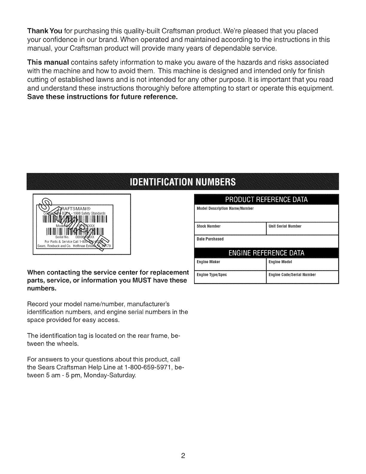
AFTSMAN®
8 Siiititiitidiiii _
Model Description Name/Number
Stock Number Unit Serial Number
Date Purchased
When contacting the service center for replacement
parts, service, or information you MUST have these
numbers.
Engine Maker Engine Model
EngineType/Spe¢ Engine Cede/Serial Number
Record your model name/number, manufacturer's
identification numbers, and engine serial numbers in the
space provided for easy access.
The identification tag is located on the rear frame, be-
tween the wheels.
For answers to your questions about this product, call
the Sears Craftsman Help Line at 1-800-659-5971, be-
tween 5 am - 5 pm, Monday-Saturday.
2
Identification Numbers
Warranty Statement
Emissions Statement
Operator Safety
Features and Controls
Operation
2 Maintenance 17
3 Storage 21
4 Troubleshooting 22
5 Specifications 24
10 Service Parts PTS-1
11
CRAFTSMAN FULL WARRANTY
When operated and maintained according to all supplied instructions, if any non-expendable part of this riding equip-
ment fails due to a defect in material or workmanship within two years from the date or purchase, call 1-800-659-5917 to
arrange for free in-home repair.
The frame and front axle will be repaired free of charge for five years from the date of purchase if defective in material or
workmanship.
All of the above warranty coverage applies for only 90 days from the date of purchase if this riding equipment is ever
used for commercial or rental purposes.
In all cases, if repair proves impossible, the riding equipment will be replaced free of charge with the same or an equiva-
lent model.
The battery will be replaced free of charge for 90 days from the date of purchase if defective in material or workmanship
(or testing proves that it will not hold a charge).
This warranty covers ONLY defects in material and workmanship. Sears will NOT pay for:
oExpendable items that become worn during normal use, including but not limited to blades, spark plugs, air cleaners,
belts, and oil filters.
oStandard maintenance servicing, oil changes, or tune-ups.
•Tire replacement or repair caused by punctures from outside objects, such as nails, thorns, stumps, or glass.
•Tire or wheel replacement or repair resulting from normal wear, accident, or improper operation or maintenance.
•Repairs necessary because of operator abuse, including but not limited to damage caused by towing objects beyond
the capability of the riding equipment, impacting objects that bend the frame or crankshaft, or over-speeding the en-
gine.
•Repairs necessary because of operator negligence, including but not limited to, electrical and mechanical damage
caused by improper storage, failure to use the proper grade and amount of engine oil, failure to keep the deck clear of
flammable debris, or failure to maintain the riding equipment according to the instructions contained in the operator's
manual.
oEngine (fuel system) cleaning or repairs caused by fuel determined to be contaminated or oxidized (stale). In general,
fuel should be used within 30 days of its purchase date.
•Normal deterioration and wear of the exterior finishes, or product label replacement.
This warranty applies only while this product is within the United States.
This warranty gives you specific legal rights, and you may also have other rights which vary from state to state.
Sears, Roebuck and Co., Hoffman Estates, IL 60179
3
EmissionsControlSystemWarrantyStatement
California,United States and Canada Emissions Control Defects Warranty
Statement
TheCaliforniaAir ResourceBoard(CARB),U.S.EPAadnB&Sarepleasedto explainthe
EmissionsControlSystemWarrantyonyour smalloff-roadengine(SORE).In Califor-
nai,newsmalloff-roadenginesmodelyear2006andlatermust bedesigned,built and
equippedto meetthe State'sstrigentanti-smogstandards.Elsewherein theUnitedStates,
newnon-road,spark-ignitionenginescertifiedfor modelyear1997and latermustmeet
similarstandardssetforth bythe U.S.EPA.B&Smustwarrantthe emissionscontrolsys-
tem on yourenginefor the periodsof timelistedbelow,providedtherehasbeenno abuse,
neglector impropermaintenanceof your smalloff-roadengine.
Youremissionscontrolsystemincludespartssuchasthe carburetor,aircleaner,ignition
system,fuelline,mufflerandcatalyticconverter.Alsoincludedmaybeconnectorsand
otheremissionsrelatedassemblies.
Wherea warrantableconditionexists,B&S will repairyour small off-roadengineat no
cost to youincludingdiagnosis,partsandlabor.
Briggs & Stratton Emissions Control Defects Warranty Coverage
Smalloff-roadenginesarewarrantedrelativeto emissionscontrol partsdefectsfor a
periodof two years,subjectto provisionssetforth below.If anycoveredpart onyour
engineis defective,the partwill be repairedor replacedby B&S.
Owner's Warranty Responsibility
Asthesmalloff-roadengineowner,you are responsiblefor the performanceof the required
maintenancelistedinyour Operatingand MaintenanceInstructions.B&Srecommends
thatyou retainallyour receiptscoveringmaintenanceon yoursmalloff-roadengine,but
B&Scannotdenywarrantysolelyfor the lackof receiptsor foryour failureto ensurethe
performanceof all scheduledmaintenance.
Asthesmalloff-roadengineowner,you shouldhoweverbeawarethat B&Smaydenyyou
warrantycoverageif your smalloff-roadengineor a part hasfaileddueto abuse,neglect,
impropermaintenanceor unapprovedmodifications.
Youare responsiblefor presentingyoursmalloff-roadengineto anAuthorizedB&S Service
Dealeras soonasa problemexists.The undisputedwarrantyrepairsshouldbecompleted
in a reasonableamountof time,notto exceed30 days.
If you haveanyquestionsregardingyour warrantyrightsandresponsibilities,you should
contacta B&S ServiceRepresentativeat (414)259-5262.
Theemissionswarrantyis a defectswarranty.Defectsarejudgedon normalengineperfor-
mance.Thewarrantyis not relatedto anin-useemissionstest.
The following arespecificprovisions relativeto your EmissionsControl DefectsWarrantyCoverage.It is in addition to the B&S enginewarrantyfor non-regulatedenginesfound
in the Operatingand MaintenanceInstructions.
1. WarrantedParts 3.
Coverageunderthis warranty extendsonly to the parts listed below(the emissions
control systems parts)to the extent thesepartswere presenton the engine
purchased.
a. FuelMeteringSystem
*Coldstart enrichmentsystem (soft choke)
*Carburetorand internal parts
*Fuelpump 4.
*Fuelline, fuel line fittings, clamps
*Fueltank, capand tether
*Carboncanister
b. Air InductionSystem
*Air cleaner
*Intakemanifold
*Purgeandvent line
c. Ignition System 5.
*Sparkplug(s)
*Magnetoignitionsystem
d. CatalystSystem
*Catalyticconverter
*Exhaustmanifold
*Air injection systemor pulsevalve
e. MiscellaneousItems Usedin AboveSystems
*Vacuum,temperature,position, time sensitivevalves andswitches
*Connectorsand assemblies
2. Lengthof Coverage
B&Swarrants to the initial ownerand eachsubsequentpurchaserthat the Warranted 6.
Partsshallbe free from defectsin materialsand workmanshipwhich causedthe
failureof the Warrantedpartsfor a periodof two yearsfrom the datethe engineis
deliveredto a retailpurchaser.
NoCharge
Repairor replacementof anyWarrantedPart will be performed at no chargeto the
owner,including diagnosticlabor which leadsto the determinationthat a War-
rantedPart is defecttive,if the diagnosticwork is performed at an AuthorizedB&S
ServiceDealeras listedin the "Yellow Pages"under "Engines,Gasoline,""Gasoline
Engines,""LawnMowers," or similarcategory.
ClaimsandCoverageExclusions
Warrantyclaims shallbe filed in accordancewith the provisionsof the B&S Engine
WarrantyPolicy.Warrantycoverageshall beexcludedfor failures of WarrantedParts
which arenot original B&Sparts or becauseof abuse,neglector improper main-
tenanceasset forth in the B&S EngineWarrantyPolicy.B&S is not liableto cover
failuresof WarrantedPartscausedbythe useof add-on, non-original,or modified
parts.
Maintenance
AnyWarrantedPartwhich is not scheduledfor replacementas requiredmaintenance
or which is scheduledonly for regularinspectionto the effect of "repair or replaceas
necessary"shall bewarranted asto defectsfor the warranty period. Any Warranted
Part which is scheduledfor replacementas requiredmaintenanceshall bewarranted
asto defectsonly for the periodof time up to the first scheduledreplacementfor
that part.Any replacementpartthat is equivalentin performanceand durabilitymay
be usedin the performanceof any maintenanceor repairs.The owneris responsible
for the performanceof all requiredmaintenance,as definedin the B&S Operating
and MaintenanceInstructions.
ConsequentialCoverage
Coveragehereundershallextend to the failure of any enginecomponentscausedby
the failure of anyWarranted Partstill underwarranty.
Enginesthat are certifiedto meetthe CaliforniaAir ResourcesBoard(CARB)Emis-
sions Standardmust display information regardingthe EmissionsDurabilityperiod
and the Air Index. Briggs & Stratton makesthis information availableto the con-
sumer on our emissionslabels.Theengine emissionslabel will indicatecertification
information.
The Emissions DurabilityPerioddescribesthe numberof hours of actualrunning
time for which the engineis certifiedto be emissions compliant,assuming proper
maintenancein accordancewiht the Operatingand MaintenanceInstructions. The
following categoriesare used:
Moderate:
Engineis certifiedto beemissionscompliant for 125 hours of actual runningtime.
Intermediate:
Engineis certifiedto beemissionscompliant for 250 hours of actual runningtime.
Extended:
Engineis certifiedto be emissionscompliant for 500 hours of actual enginerunningtime.
Forexample,atypical walk-behindlawn mower is used20 to 25 hoursper year.There-
fore,the EmissionsDurability Period of an enginewith an intermediate rating would
equateto 10 to 12 years.
Briggs & Strattonenginesare certifiedto meetthe UnitedStatesEnvironmentalProtec-
tion Agency(ESEPA)Phase2 emissions standards.ForPhase2 certifiedengines,the
EmissionsCompliancePeriodreferredto on the EmissionsCompliancelabel indicatesthe
number of operatinghours for which the enginehasbeenshownto meet Federalemis-
sions requirements.
Forengineslessthan 225 cc displacement.
CategoryC=125 hours,CategoryB=250 hours,CategoryA= 500 hours
Forenginesof 225 ccor more displacement.
CategoryC=250 hours,CategoryB=500 hours,CategoryA= 1000hours
-4
important Safety instructions
SAVE THESE iNSTRUCTiONS - This manual contains
important instructions that should be followed during the
initial set-up, the operation, and the maintenance of the
equipment.
--'] WARNING The exhaust from this
engine product
contains chemicals known to the State of California to
cause cancer, birth defects, or other reproductive harm.
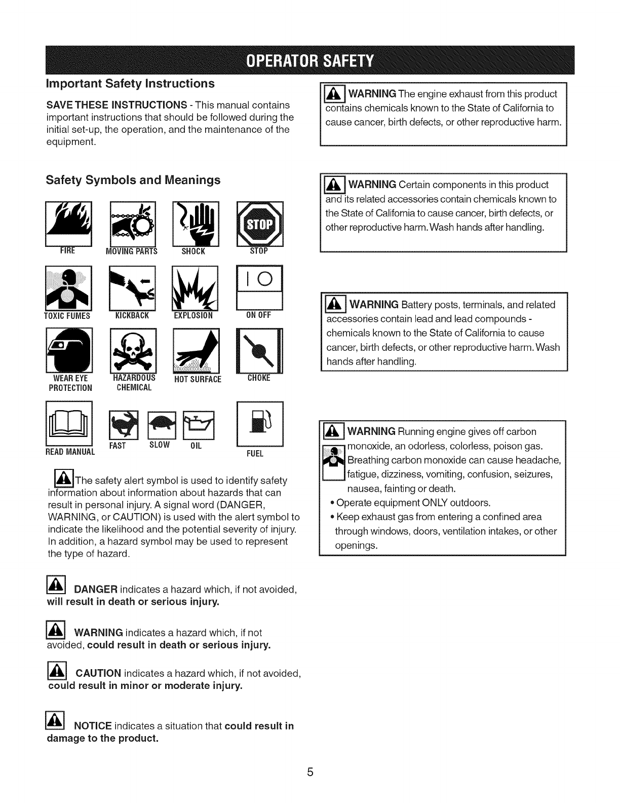
Safety Symbols and Meanings
FiRE MOVINGPARTS SHOCK STOP
TOXICFUMES EXPLOSION ONOFFKICKBACK
HAZARDOUS
CHEMICAL
WEAREYE NOTSURFACE CHOKE
PROTECTION
_ WARNING Certain in this
components product
and its related accessories contain chemicals known to
the State of California to cause cancer, birth defects, or
other reproductive harm. Wash hands after handling.
I_-----IWARNING Battery posts, terminals, and related
accessories contain lead and lead compounds -
chemicals known to the State of California to cause
cancer, birth defects, or other reproductive harm. Wash
hands after handling.
m
BEADMANUAL FAST SLOW OiL FUEL
_The safety alert symbol is used to identify safety
information about information about hazards that can
result in personal injury. A signal word (DANGER,
WARNING, or CAUTION) is used with the alert symbol to
indicate the likelihood and the potential severity of injury.
In addition, a hazard symbol may be used to represent
the type of hazard.
DANGER indicates a hazard which, if not avoided,
will result in death or serious injury.
WARNING indicates a hazard which, if not
avoided, could result in death or serious injury.
r_ CAUTION indicates a hazard which, if not avoided,
could result in minor or moderate injury.
WARNING Running engine gives off carbon
1_ onoxide, an odorless, colorless, poison gas.
Breathing carbon monoxide can cause headache,
fatigue, dizziness, vomiting, confusion, seizures,
nausea, fainting or death.
•Operate equipment ONLY outdoors.
•Keep exhaust gas from entering a confined area
through windows, doors, ventilation intakes, or other
openings.
[_ NOTICE indicates a situation that could result in
damage to the product.
5
WARNING: This cutting machine is capable of amputating hands and feet and can throw objects that can
cause injury and damage! Failure to comply with the following SAFETY instructions could result in serious
injury or death to the operator or bystanders. The owner of the machine must understand these instructions
and must allow only persons who understand these instructions to operate machine. Each person operating
the machine must be of sound mind and body and must not be under the influence of any substance, which
might impair vision, dexterity or judgment.
Protection for Children
Tragic accidents can occur if the operator is not alert to
the presence of children. Children are often attracted to
the machine and the mowing activity. Never assume that
children will remain where you last saw them.
1. KEEP children out of the mowing area and under the
watchful care of a responsible adult.
2. DO NOT allow children or others to ride on machine,
attachments or towed equipment (even with the
blades OFF). They may fall and be seriously injured.
3. ALLOW only responsible adults & teenagers with
mature judgment under close adult supervision to
operate machine.
4. DO NOT operate blades in reverse. STOP BLADES.
LOOK and SEE behind and down for children, pets
and hazards before and while backing.
5. USE EXTRA CARE when approaching blind corners,
shrubs, trees, or other objects that may obscure vi-
sion.
Protection against Tipovers
Slopes are a major factor related to loss-of-control and
tip-over accidents, which can result in severe injury or
death. All slopes require extra CAUTION. If you cannot
back up the slope or if you feel uneasy on the slope, DO
NOT mow it. Use extra care with grass catchers or other
attachments; these affect the handling and the stability of
the machine. Refer to the Slope Guide at the end of this
section.
1. DO NOT operate machine on slopes exceeding 10
degrees, which is 3.5 feet (1.1 m) vertically for every
20 feet (6.1 m) horizontally.
2. Turn blades OFF when traveling uphill. Use a slow
speed and avoid sudden or sharp turns.
3. DO NOT operate machine back and forth across face
of slopes. Operate up and down. Practice on slopes
with blades off.
4. AVOID starting, stopping or turning on slopes. If
machine stops going uphill or tires lose traction, turn
blades OFF and back slowly straight down the slope.
5. STAY ALERT for holes and other hidden hazards. Tall
grass can hide obstacles. Keep away from ditches,
washouts, culverts, fences and protruding objects.
6. KEEP A SAFE DISTANCE of at least 3 feet (.9 meters)
away from edge of ditches and other drop offs. The
machine could turn over if an edge caves in.
7. Always begin forward motion slowly and with caution.
8. Use weights or a weighted load carrier in accordance
with instructions supplied with a grass catcher. DO
NOT operate machine on slopes exceeding 10 de-
grees.
9. DO NOT put your foot on the ground to try to stabilize
the machine.
10. DO NOT operate machine on wet grass. Reduced
traction could cause sliding.
11. Choose a low enough speed setting so that you will
not have to stop or shift on a slope. Tires may lose
traction on slopes even though the brakes are func-
tioning properly.
12. DO NOT operate machine under any condition where
traction, steering or stability is doubtful.
13. Always keep the machine in gear when going down
slopes. DO NOT shift to neutral (or actuate hydro roll
release) and coast downhill.
Before Mowing
1. Read, understand, and follow instructions and warn-
ings in this manual and on the machine, engine and
attachments. Know the controls and the proper use of
the machine before starting.
2. Only mature, responsible persons shall operate the
machine and only after proper instruction.
3. Data indicates that operators age 60 and above,
are involved in a large percentage of mower-related
injuries. These operators should evaluate their ability
to operate the mower safely enough to protect them-
selves and others from serious injury.
4. Handle fuel with extra care. Fuels are flammable
and vapors are explosive. Use only an approved fuel
container. DO NOT remove fuel cap or add fuel with
engine running. Add fuel outdoors only with engine
stopped and cool. Clean spilled fuel from machine. DO
NOT smoke.
5. Practice operation of machine with BLADES OFF to
learn controls and develop skills.
6. Check the area to be mowed and remove all objects
such as toys, wire, rocks, limbs and other objects that
could cause injury if thrown by blade or interfere with
mowing.
7. Keep people and pets out of mowing area. Immedi-
ately STOP blades, STOP engine, and STOP machine
if anyone enters the area.
8. Check shields, deflectors, switches, blade controls
and other safety devices frequently for proper opera-
tion and location.
9. Make sure all safety decals are clearly legible. Re-
place if damaged.
10. Protect yourself when mowing by wearing safety
glasses, a dust mask, long pants and substantial
footwear.
6
11. Know how to STOP blades and engine quickly in
preparation for emergencies.
12. Use extra care when loading or unloading the ma-
chine into a trailer or truck.
13. Check grass catcher components frequently for signs
of wear or deterioration and replace as needed to
prevent injury from thrown objects going through weak
or worn spots.
Safe Handling of Gasoline
To avoid personal injury or property damage, use ex-
treme care in handling gasoline. Gasoline is extremely
flammable and the vapors are explosive.
1. Extinguish all cigarettes, cigars, pipes and other
sources of ignition.
2. Use only an approved fuel container.
3. DO NOT remove fuel cap or add fuel with the engine
running. Allow the engine to cool before refueling.
4. DO NOT refuel the machine indoors.
5. DO NOT store the machine or fuel container inside
where there is an open flame, spark or pilot light such
as on a water heater or other appliances.
6. DO NOT fill fuel containers inside a vehicle or on a
truck or trailer bed with a plastic liner. Always place the
containers on the ground away from the vehicle before
filling.
7. Remove gas-powered equipment from the vehicle or
trailer and refuel it on the ground. If this is not possi-
ble, then refuel equipment using a portable container,
rather than a gasoline dispenser nozzle.
8. DO NOT start gas powered equipment in enclosed
vehicles or trailers.
9. Keep the nozzle in contact with the rim of the fuel tank
or container opening at all times until fueling is com-
plete. DO NOT use a nozzle lock-open device
10. If fuel is spilled on clothing, change clothing immedi-
ately.
11. Never overfill a fuel tank. Replace fuel cap and tighten
securely.
General Operating Safety
1. Mount and dismount machine from left side. Keep
clear of discharge opening at all times.
2. Start engine from operator's seat. Make sure blades
are OFF and parking brake is set.
3. DO NOT leave machine with engine running. STOP
engine, STOP blades, SET brake, and Remove key
before leaving operators position of any reason.
4. DO NOT operate machine unless properly seated with
feet on rests or pedal(s).
5. STOP BLADES and ENGINE and make sure blades
have stopped before removing grass catcher or un-
clogging mower to prevent loss of fingers or hand.
6. Blades must be OFF except when cutting grass. Set
blades in highest position when mowing over rough
ground.
7. Keep hands and feet away from rotating blades un-
derneath deck. DO NOT place foot on ground while
BLADES are ON or machine is in motion.
8. DO NOT operate machine without entire grass
catcher or guards in place and working. DO NOT point
discharge at people, passing cars, windows or doors.
9. Slow down before turning.
10. Watch out for traffic when near or crossing roadways.
11. STOP engine immediately after striking an obstruc-
tion. Inspect machine and repair damage before
resuming operation.
12. Operate machine only in daylight or with good artifi-
cial light.
13. Move joystick (if equipped) SLOWLY to maintain con-
trol during speed and directional changes.
14. DO NOT operate engine in enclosed areas. Engine
exhaust gases contain carbon monoxide, a deadly
poison.
15. DO NOT discharge material against a wall or obstruc-
tion. Material may ricochet back towards the operator.
16. Only use accessories approved by the manufacturer.
See manufacturer's instructions for proper operation
and installation of accessories.
7

Towing
1. Tow only with a machine that has a hitch designed for
towing. DO NOT attach towed equipment except at the
hitch point.
2. Follow the manufacturer's recommendation for weight
limits for towed equipment and towing on slopes.
3. DO NOT allow children or others on towed equipment.
4. On slopes, the weight of the towed equipment may
cause loss of traction and loss of control.
5. Travel slowly and allow extra distance to stop.
6. Exercise CAUTION when pulling loads. Limit loads to
those you can safely control and attach loads to hitch
plate as specified in the attachment instructions.
Maintenance Safety
1. DO NOT store machine or fuel container inside where
fumes may reach an open flame, spark or pilot light
such as in a water heater, furnace, clothes dryer or
other gas appliance. Allow engine to cool before stor-
ing machine in an enclosure. Store fuel container out
of the reach of children in a well ventilated, unoccu-
pied building.
2. Keep engine free of grass, leaves or excess grease to
reduce fire hazard and engine overheating.
3. When draining fuel tank, drain fuel into an approved
container outdoors and away from open flame.
4. Always provide adequate ventilation when running
engine. Exhaust gases contain carbon monoxide, an
odorless and deadly poison.
5. Disconnect negative (black) cable from battery before
performing maintenance or service. Cranking engine
could cause injury.
6. DO NOT work under machine without safety blocks.
7. Service engine and make adjustments only when en-
gine is stopped. Remove spark plug wire(s) from spark
plug(s) and secure wire(s) away from spark plug(s).
9. DO NOT change engine governor speed settings or
overspeed engine.
10. Mower blades are sharp and can cut. Wrap the blades
or wear heavy leather gloves and use CAUTION when
handling them.
11. DO NOT test for spark by grounding spark plug next
to spark plug hole; spark plug could ignite gas exiting
engine.
12. Maintain or replace safety and instruction labels as
necessary.
8
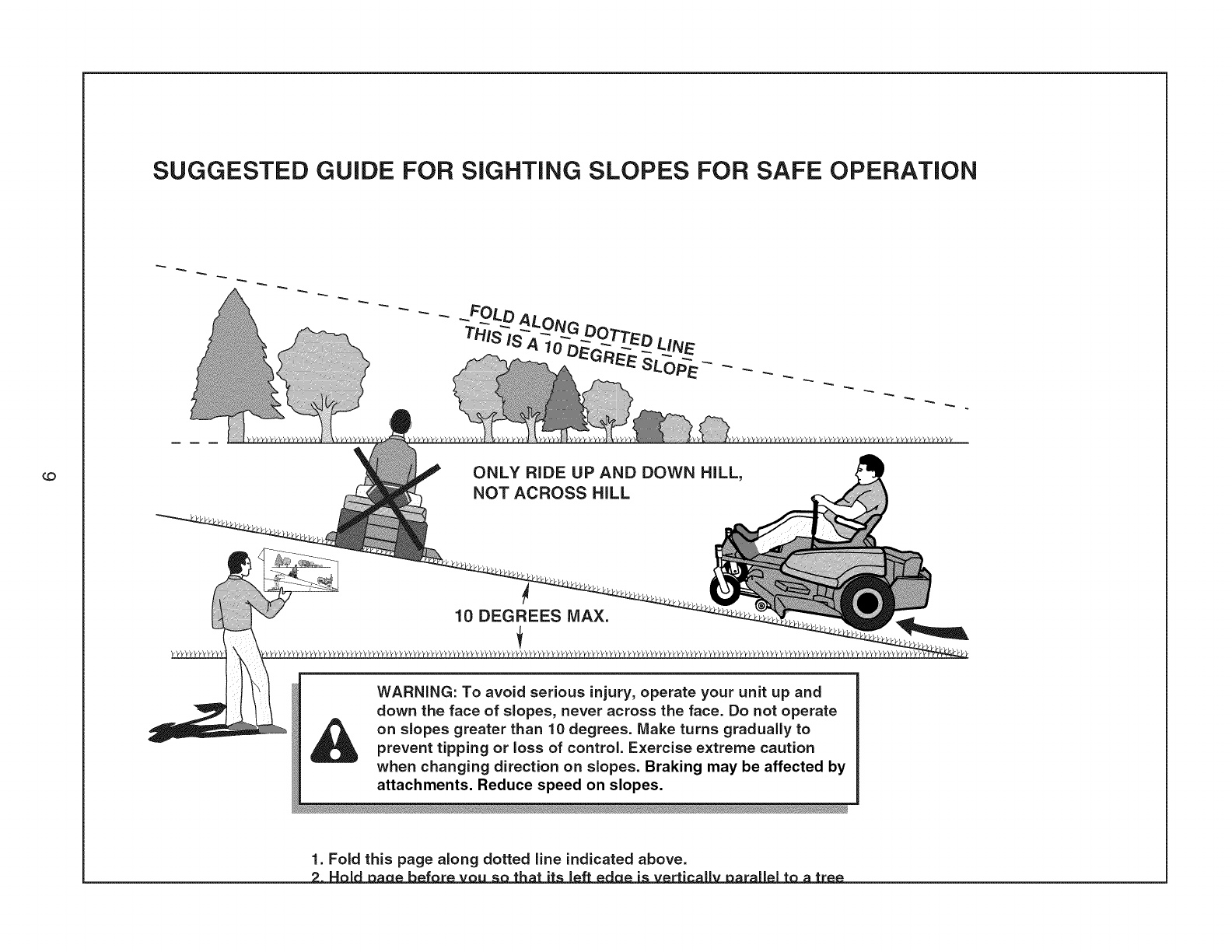
SUGGESTED GUIDE FOR SiGHTiNG SLOPES FOR SAFE OPERATION
ONLY RIDE UP AND DOWN HILL,
NOT ACROSS HILL
10 DEGREES MAX.
WARNING: To avoid serious injury, operate your unit up and
down the face of slopes, never across the face. Do not operate
on slopes greater than 10 degrees. Make turns gradually to
prevent tipping or loss of control. Exercise extreme caution
when changing direction on slopes. Braking may be affected by
attachments. Reduce speed on slopes.
1. Fold this page along dotted line indicated above.
= = =

NOTICE: The figures and illustrations in this manual are provided for reference only and may differ from your specific
model.
A. Steering Wheel E Blade Pedal
B. Engine Speed Control (hidden from view) G. Blade Lever
C. Ignition Switch H Discharge Deflector
D. Clutch/Brake Pedal J. Override Control
E. Parking Brake Latch K. Transmission Shift Lever
L. Fuel Tank
10
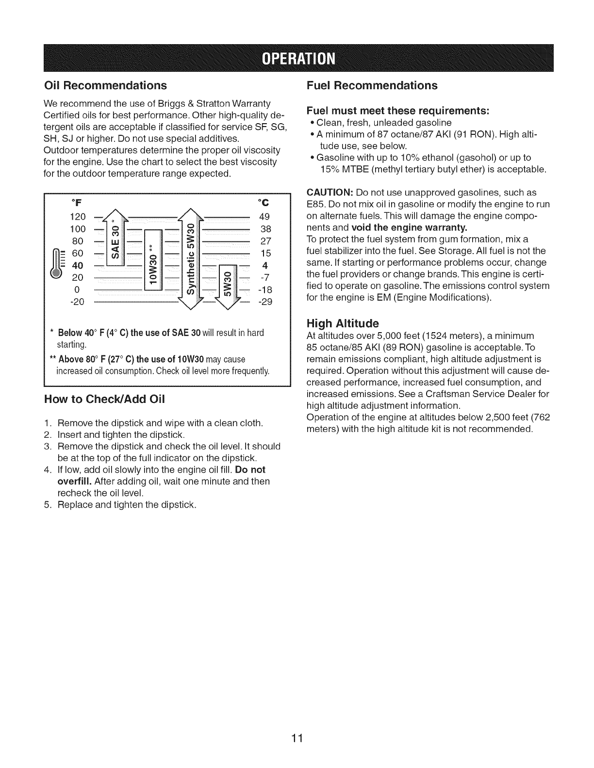
Oil Recommendations Fuel Recommendations
We recommend the use of Briggs & Stratton Warranty
Certified oils for best performance. Other high-quality de-
tergent oils are acceptable if classified for service SF, SG,
SH, SJ or higher. Do not use special additives.
Outdoor temperatures determine the proper oil viscosity
for the engine. Use the chart to select the best viscosity
for the outdoor temperature range expected.
Fuel must meet these requirements:
•Clean, fresh, unleaded gasoline
• A minimum of 87 octane/87 AKI (91 RON). High alti-
tude use, see below.
Gasoline with up to 10% ethanol (gasohol) or up to
15% MTBE (methyl tertiary butyl ether) is acceptable.
°F
120
100
8O
6O
40
20
0
-20
°C
_i;: _ 38
_iiiiiii 27
oiiiiJii_ 15
i!iiii-- -- 4
_iiiii
=iliiui -7
_-18
-29
* Below 400F (40C) the use of SAE 30will resultinhard
starting.
** Above800F (270C) the use of 10W30maycause
increasedoil consumption.Checkoil levelmore frequently.
How to Check/Add Oil
1. Remove the dipstick and wipe with a clean cloth.
2. Insert and tighten the dipstick.
3. Remove the dipstick and check the oil level. It should
be at the top of the full indicator on the dipstick.
4. If low, add oil slowly into the engine oil fill. Do not
overfill. After adding oil, wait one minute and then
recheck the oil level.
5. Replace and tighten the dipstick.
CAUTION: Do not use unapproved gasolines, such as
E85. Do not mix oil in gasoline or modify the engine to run
on alternate fuels. This will damage the engine compo-
nents and void the engine warranty.
To protect the fuel system from gum formation, mix a
fuel stabilizer into the fuel. See Storage. All fuel is not the
same. If starting or performance problems occur, change
the fuel providers or change brands. This engine is certi-
fied to operate on gasoline. The emissions control system
for the engine is EM (Engine Modifications).
High Altitude
At altitudes over 5,000 feet (1524 meters), a minimum
85 octane/85 AKI (89 RON) gasoline is acceptable. To
remain emissions compliant, high altitude adjustment is
required. Operation without this adjustment will cause de-
creased performance, increased fuel consumption, and
increased emissions. See a Craftsman Service Dealer for
high altitude adjustment information.
Operation of the engine at altitudes below 2,500 feet (762
meters) with the high altitude kit is not recommended.
11
How to Add Fuel
_=_ WARNING Gasoline and its vapors are extremely
_ flammable and explosive.Fire or explosion can cause severe burns or death.
N
When Adding Fuel
* Turn engine off and let engine cool at least 2 minutes
before removing the fuel cap.
* Fill fuel tank outdoors or in well-ventilated area.
* Do not overfill fuel tank. To allow for expansion of
gasoline, do not fill above the bottom of the fuel tank
neck.
* Keep gasoline away from sparks, open flames, pilot
lights, heat, and other ignition sources.
* Check fuel lines, tank, cap, and fittings frequently for
cracks or leaks. Replace if necessary.
* If fuel spills, wait until it evaporates before starting
engine.
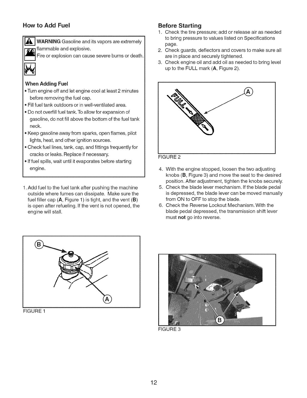
1. Add fuel to the fuel tank after pushing the machine
outside where fumes can dissipate. Make sure the
fuel filler cap (A, Figure 1) is tight, and the vent (B)
is open after refueling. If the vent is not opened, the
engine will stall.
Before Starting
1. Check the tire pressure; add or release air as needed
to bring pressure to values listed on Specifications
page.
2. Check guards, deflectors and covers to make sure all
are in place and securely tightened.
3. Check engine oil and add oil as needed to bring level
up to the FULL mark (A, Figure 2).
FIGURE 2
4. With the engine stopped, loosen the two adjusting
knobs (B, Figure 3) and move the seat to the desired
position. After adjustment, tighten the knobs securely.
5. Check the blade lever mechanism. If the blade pedal
is depressed, the blade lever can be moved manually
from ON to OFF to stop the blade.
6. Check the Reverse Lockout Mechanism. With the
blade pedal depressed, the transmission shift lever
must not go into reverse.
FIGURE 1
12
FIGURE 3
Starting Engine
WARNING Gasoline and its vapors are extremely
_ flammable and explosive.
Fire or explosion can cause severe burns or death.
N
When Starting Engine
• Ensure that spark plug, muffler, fuel cap and air cleaner
(if equipped) are in place and secured.
• Do not crank the engine with the spark plug removed.
• If engine floods, set choke (if equipped) to OPEN/RUN
position, move throttle (if equipped) to FAST postion
and crank until engine starts.
WARNING Running engine gives off carbon
_] onoxide, an odorless, colorless, poison gas.
Breathing carbon monoxide can cause headache,
fatigue, dizziness, vomiting, confusion, seizures,
nausea, fainting or death.
• Operate equipment ONLY outdoors.
• Keep exhaust gas from entering a confined area
through windows, doors, ventilation intakes, or other
openings.
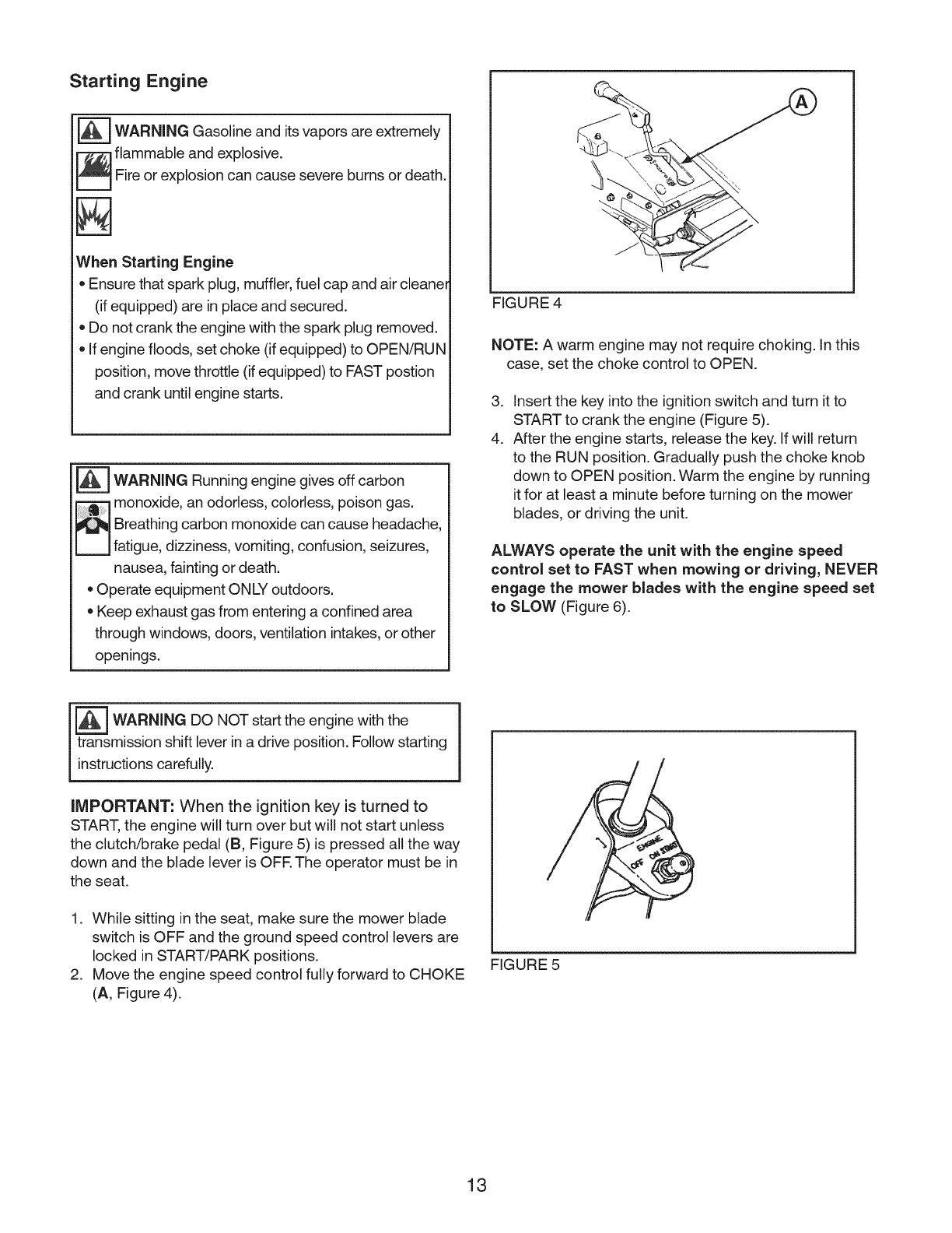
FIGURE 4
NOTE: A warm engine may not require choking. In this
case, set the choke control to OPEN.
3. Insert the key into the ignition switch and turn it to
START to crank the engine (Figure 5).
4. After the engine starts, release the key. If will return
to the RUN position. Gradually push the choke knob
down to OPEN position. Warm the engine by running
it for at least a minute before turning on the mower
blades, or driving the unit.
ALWAYS operate the unit with the engine speed
control set to FAST when mowing or driving, NEVER
engage the mower blades with the engine speed set
to SLOW (Figure 6).
_ WARNING DO NOT start the with the
engine
transmission shift lever in a drive position. Follow starting
instructions carefully.
iMPORTANT: When the ignition key is turned to
START, the engine will turn over but will not start unless
the clutch/brake pedal (B, Figure 5) is pressed all the way
down and the blade lever is OFR The operator must be in
the seat.
1. While sitting in the seat, make sure the mower blade
switch is OFF and the ground speed control levers are
locked in START/PARK positions.
2. Move the engine speed control fully forward to CHOKE
(A, Figure 4).
FIGURE 5
13
/
1
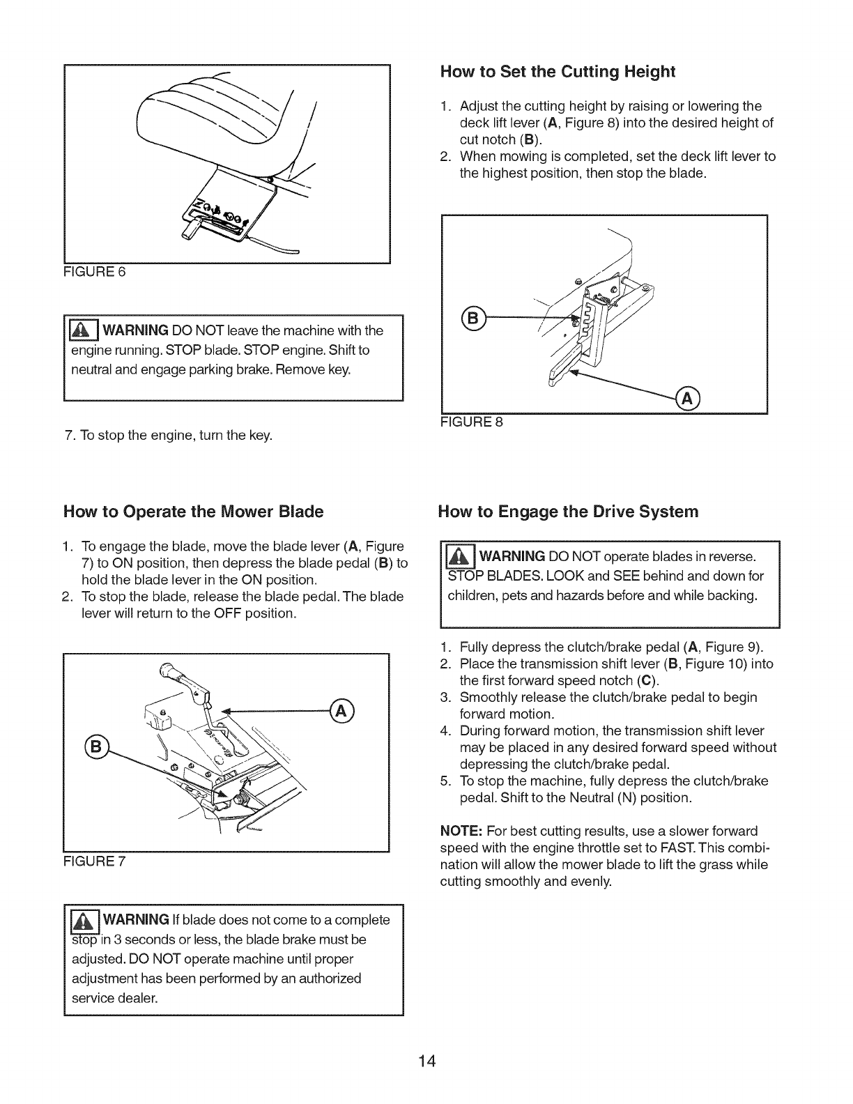
How to Set the Cutting Height
1. Adjust the cutting height by raising or lowering the
deck lift lever (A, Figure 8) into the desired height of
cut notch (B).
2. When mowing is completed, set the deck lift lever to
the highest position, then stop the blade.
FIGURE 6
_WARNING DO NOT leave the machine with the
I engine running. STOP blade. STOP engine. Shift to
l neutral and engage parking brake. Remove key.
7. To stop the engine, turn the key.
®
FIGURE 8
How to Operate the Mower Blade
1. To engage the blade, move the blade lever (A, Figure
7) to ON position, then depress the blade pedal (B) to
hold the blade lever in the ON position.
2. To stop the blade, release the blade pedal. The blade
lever will return to the OFF position.
FIGURE 7
s_op WARNING If blade does not come to a complete
in 3 seconds or less, the blade brake must be
adjusted. DO NOT operate machine until proper
adjustment has been performed by an authorized
service dealer.
How to Engage the Drive System
WARNING DO NOT blades in
operate reverse.
STOP BLADES. LOOK and SEE behind and down for
children, pets and hazards before and while backing.
1. Fully depress the clutch/brake pedal (A, Figure 9).
2. Place the transmission shift lever (B, Figure 10) into
the first forward speed notch (C).
3. Smoothly release the clutch/brake pedal to begin
forward motion.
4. During forward motion, the transmission shift lever
may be placed in any desired forward speed without
depressing the clutch/brake pedal.
5. To stop the machine, fully depress the clutch/brake
pedal. Shift to the Neutral (N) position.
NOTE: For best cutting results, use a slower forward
speed with the engine throttle set to FAST.This combi-
nation will allow the mower blade to lift the grass while
cutting smoothly and evenly.
14
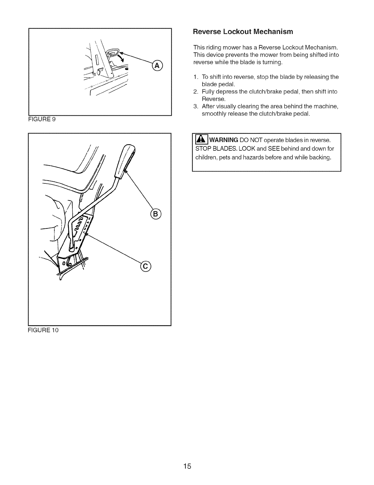
FIGURE 9
Reverse Lockout Mechanism
This riding mower has a Reverse Lockout Mechanism.
This device prevents the mower from being shifted into
reverse while the blade is turning.
1. To shift into reverse, stop the blade by releasing the
blade pedal.
2. Fully depress the clutch/brake pedal, then shift into
Reverse.
3. After visually clearing the area behind the machine,
smoothly release the clutch/brake pedal.
®
[_WARNING DO NOT operate blades in reverse.
STOP BLADES. LOOK and SEE behind and down for
children, pets and hazards before and while backing.
FIGURE 10
15
Reverse Lockout Override How to Set the Parking Brake
F_ AMPUTATION HAZARD
WARNING
F_ ailure to obey these rules could result in loss of
control of unit, severe personal injury or death
to you, or bystanders, or damage to property or
equipment.
• Do not mow when children or others are present.
Do not carry riders (especially children) even with the
blades off. They may fall off or return for another ride
when you are not expecting it.
Look down and behind before and while backing.
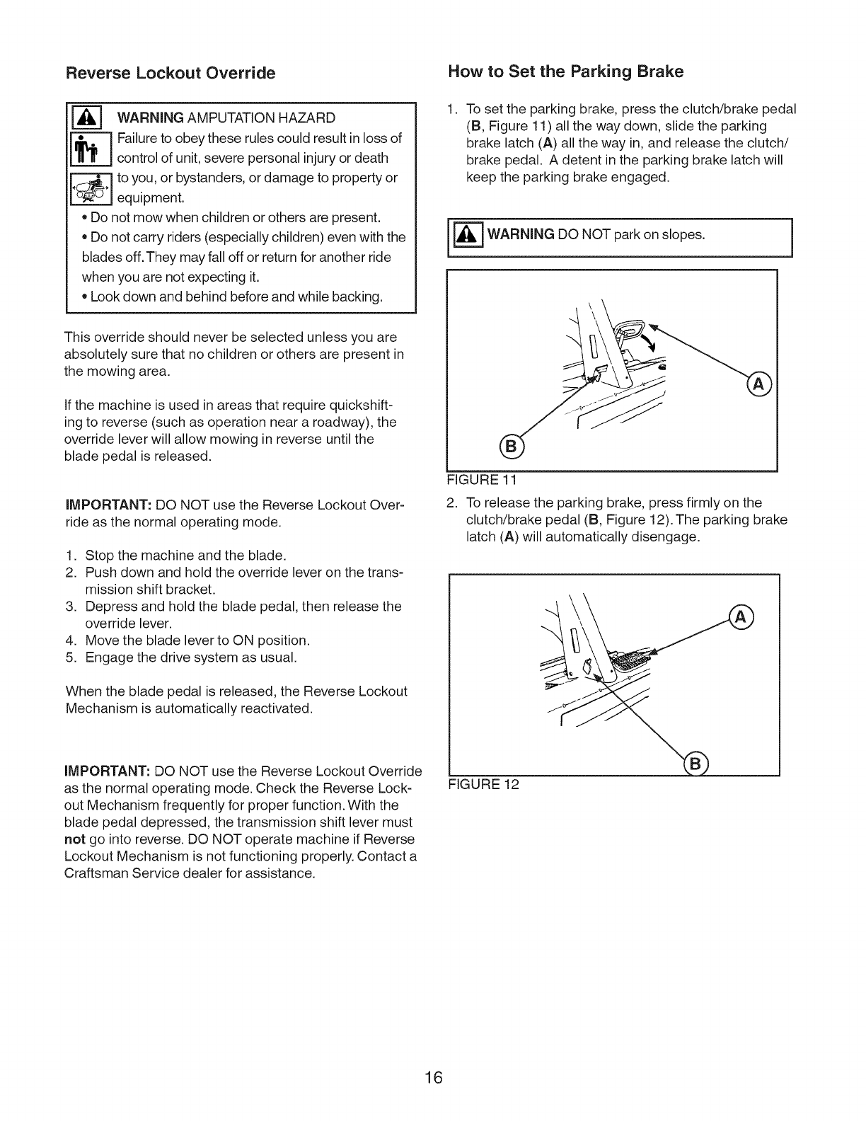
.To set the parking brake, press the clutch/brake pedal
(B, Figure 11) all the way down, slide the parking
brake latch (A) all the way in, and release the clutch/
brake pedal. A detent in the parking brake latch will
keep the parking brake engaged.
[_ WARNING DO NOT park on slopes.
This override should never be selected unless you are
absolutely sure that no children or others are present in
the mowing area.
If the machine is used in areas that require quickshift-
ing to reverse (such as operation near a roadway), the
override lever will allow mowing in reverse until the
blade pedal is released.
IMPORTANT: DO NOT use the Reverse Lockout Over-
ride as the normal operating mode.
1. Stop the machine and the blade.
2. Push down and hold the override lever on the trans-
mission shift bracket.
3. Depress and hold the blade pedal, then release the
override lever.
4. Move the blade lever to ON position.
5. Engage the drive system as usual.
When the blade pedal is released, the Reverse Lockout
Mechanism is automatically reactivated.
IMPORTANT: DO NOT use the Reverse Lockout Override
as the normal operating mode. Check the Reverse Lock-
out Mechanism frequently for proper function. With the
blade pedal depressed, the transmission shift lever must
not go into reverse. DO NOT operate machine if Reverse
Lockout Mechanism is not functioning properly. Contact a
Craftsman Service dealer for assistance.
FIGURE 11
2. To release the parking brake, press firmly on the
clutch/brake pedal (B, Figure 12). The parking brake
latch (A) will automatically disengage.
FIGURE 12
16
Emissions Control Equipment Maintenance Chart
Maintenance, replacement, or repair of the emissions
control devices and systems may be performed by any
non-road engine repair establishment or individual.
However, to obtain "no charge" emissions control service,
the work must be performed by a Craftsman Service or
Briggs & Stratton dealer. See the Emissions Warranty.
WARNING
Unintentional sparking can result in fire or electric
shock.
Unintentional start-up can result in entanglement,
traumatic amputation, or laceration.
[_ Fire hazard.
Before performing adjustments or repairs:
• Disconnect the spark plug wire and keep it away from
the spark plug.
Disconnect battery at negative terminal.
Use only correct tools.
Do not tamper with governor spring, links or other parts
to increase engine speed.
Replacement parts must be the same and installed in
the same postion as the original parts.
STOP engine
STOP blade
Engage parking brake
Remove key
Avoid serious burns. Allow all parts to cool before
working on machine.
Fuel filler cap and vent must be closed securely to
prevent fuel spillage.
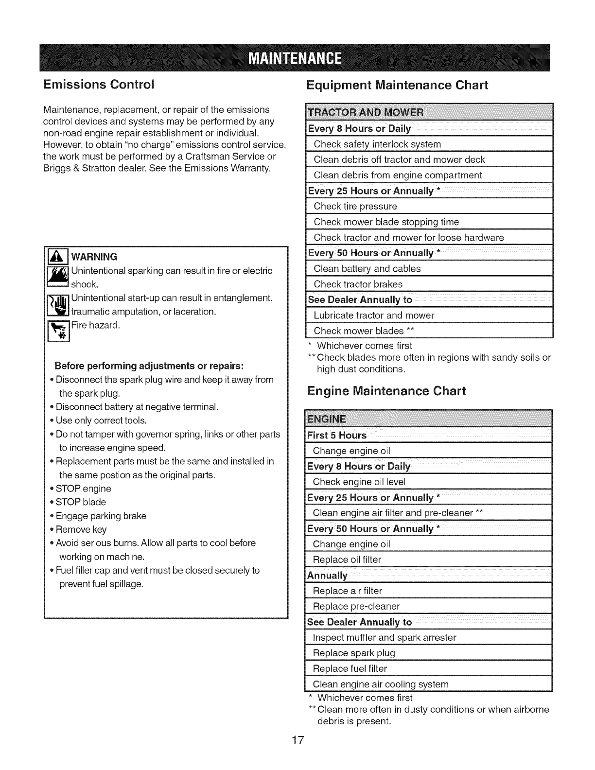
Every 8Hours or Daily
Check safety interlock system
Clean debris off tractor and mower deck
Clean debris from engine compartment
Every 25 Hours or Annually *
Check tire pressure
Check mower blade stopping time
Check tractor and mower for loose hardware
Every 50 Hours or Annually _
Clean battery and cables
Check tractor brakes
see Dealer An nually to
Lubricate tractor and mower
Check mower blades **
Whichever comes first
•* Check blades more often in regions with sandy soils or
high dust conditions.
Engine Maintenance Chart
ilii i !i i i i! !!! ! ! i !i i i iii iiiiiiiiiiiiiiiiiiiiiiiiiiiiiiiiiiiiiiiiiiiiiiiiiiiiiiiiiiiiiiiiiii!ii!iiii!ii!i ! ! !!! !!i !i i !! ! !!i!i!!! !!! ! !i !i iii iiiiiiiiiiiiiiiiiiiiiiiiiiiiiiiiiiiiiiiiiiiiiiiiiiiiiiiiiiiiiiiiiiiiiiiiiiiiiiiiiiiiiiiiiiiiiiiiiiiiiiiiiiiiiiiiiiiiiiiiiiiiiiiiiiiiiiiiiiiiiiiiiiiiiiiiiiiiiiiiiiiiiiiiiiiiiiiiiiiiiiiiiiiiiiiiiiiiiiiiiiiiiiiiiiiiiiiiiiiiiiiiiiiiiiiiiiiiiiiiiiiiiiiiiiiiiiiiiiiiiiiiiiiiiiiiiiiiiiiiiiiiiiiiiiiiiiiiiiiiiiiiiiiiiiiiiiiiiiiiiiiiiiiiiiiiiiiiiiiiiiiiiiiiiiiiiiiiiiiiiiiiiiiiiiiiiiiiiiiiiiiiiiiiiiiiiiiiiiiiiiiiiiiiiiiiiiiiiiiiiiiiiiiiiiiiiiiiiiiiiiiiiiiiiiiiiiiiiiiiiiiiiiiiiiiiiiiiiiiiiiiiiiiiiiiiiiiiiiiii i;
First 5 Hours
Change engine oil
Every 8 Hours or Daily
Check engine oil level
Every 25 Hours or Annually *
Clean engine air filter and pre-cleaner **
Every 50 Hours or Annually *
Change engine oil
Replace oil filter
Annually
Replace air filter
Replace pre-cleaner
See Dealer Annually to
Inspect muffler and spark arrester
Replace spark plug
Replace fuel filter
Clean engine air cooling system
• Whichever comes first
•* Clean more often in dusty conditions or when airborne
debris is present.
17
Check Safety Interlock System Check Reverse Lockout Mechanism
This unit is equipped with safety interlock switches. Do
not attempt to bypass safety switches, and never tamper
with safety devices.
Operational SAFETY Checks
Test 1 -- Engine should NOT crank when:
• Mower blade lever is ON, or
• Transmission is in Forward or Reverse positions, or
Clutch/brake pedal is released.
Test 2 -- Engine SHOULD crank when:
Mower blade is OFF, and
• Transmission is in Neutral (N) position, and
• Clutch/pedal is fully depressed.
Test 3-- Engine should SHUT OFF when:
Operator rises off seat with the mower blade ON
Operator rises off seat with the transmission engaged
Operator rises off seat with the parking brake OFF
Test 4 m Blade Brake Check
The mower blade should come to a complete stop within
three seconds after the mower blade is turned OFR
-] WARNING If Reverse Lockout Mechanism is
not functioning properly, DO NOT operate machine
until proper adjustment has been performed by an
authorized service dealer.
Check the function of the Reverse Lockout Mechanism
with the engine OFR
1. Depress and hold the blade pedal.
2. Depress and hold the clutch/brake pedal.
3. The transmission shift lever must not go into re-
verse.
Clean Debris Off Tractor, Mower Deck, and
Engine Compartment
] WARNING Combustible debris, such as leaves,
_ grass, brush, etc can catch fire.
• Remove accumulated debris from muffler area, mower
deck, and engine compartment.
[_ WARNING If blade does not to
come acomplete
stop in 3 seconds or less, the blade brake must be
adjusted. DO NOT operate machine until proper
adjustment has been performed by an authorized
service dealer.
Remove any grass clippings, dirt, leaves, or other debris
from the unit and engine compartment.
1. Stop engine and allow engine to cool.
2. Remove ignition key, then disconnect sparkplug wire
from sparkplug.
3. Wear safety goggles. Using a brush and/or com-
pressed air, clean debris from all surfaces of tractor
and top of mower deck.
4. Clean engine compartment thoroughly, including any
debris from the intake screen on the top of the engine,
exposed engine cooling fins, and around the air filter
assembly.
18
Check Tire Pressure Clean Battery and Cables
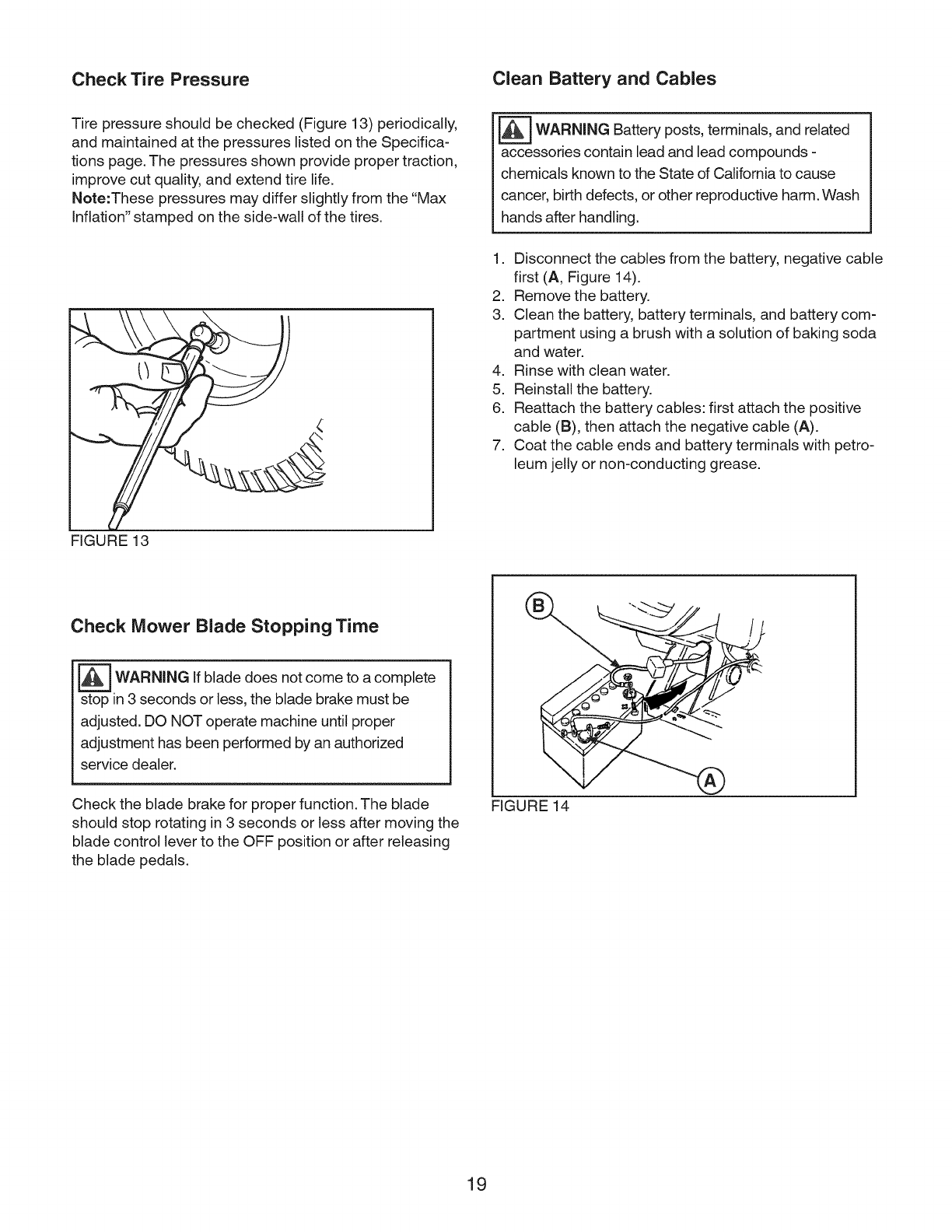
Tire pressure should be checked (Figure 13) periodically,
and maintained at the pressures listed on the Specifica-
tions page. The pressures shown provide proper traction,
improve cut quality, and extend tire life.
Note:These pressures may differ slightly from the "Max
Inflation" stamped on the side-wall of the tires.
'=]WARNING Battery posts, terminals, and related
accessories contain lead and lead compounds -
chemicals known to the State of California to cause
cancer, birth defects, or other reproductive harm. Wash
hands after handling.
1. Disconnect the cables from the battery, negative cable
first (A, Figure 14).
2. Remove the battery.
3. Clean the battery, battery terminals, and battery com-
partment using a brush with a solution of baking soda
and water.
4. Rinse with clean water.
5. Reinstall the battery.
6. Reattach the battery cables: first attach the positive
cable (B), then attach the negative cable (A).
7. Coat the cable ends and battery terminals with petro-
leum jelly or non-conducting grease.
FIGURE 13
Check Mower Blade Stopping Time
_WARNING If blade does not to
come acomplete
stop in 3 seconds or less, the blade brake must be
adjusted. DO NOT operate machine until proper
adjustment has been performed by an authorized
service dealer.
Check the blade brake for proper function. The blade
should stop rotating in 3 seconds or less after moving the
blade control lever to the OFF position or after releasing
the blade pedals.
FIGURE 14
19
Check Tractor Brakes
Check the machine brake for proper function. Engage the
park brake, and push the machine. The rear tires should
skid. Drive the machine forward and apply the brake. The
machine should come to a complete stop in less than 5 ft.
_WARNING If brake does not to
come acomplete
stop in 3 seconds or less, the blade brake must be
adjusted. DO NOT operate machine until proper
adjustment has been performed by an authorized
service dealer.
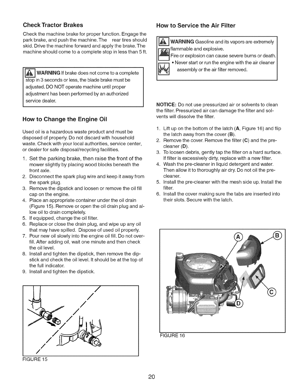
How to Change the Engine Oil
Used oil is a hazardous waste product and must be
disposed of properly. Do not discard with household
waste. Check with your local authorities, service center,
or dealer for safe disposal/recycling facilities.
1. Set the parking brake, then raise the front of the
mower slightly by placing wood blocks beneath the
front axle.
2. Disconnect the spark plug wire and keep it away from
the spark plug.
3. Remove the dipstick and loosen or remove the oil fill
cap on the engine.
4. Place an appropriate container under the oil drain
(Figure 15). Remove or open the oil drain plug and al-
low oil to drain completely.
5. If equipped, change the oil filter.
6. Replace or close the drain plug, and wipe up any oil
that may have spilled. Dispose of used oil properly.
7. Pour new oil slowly into the engine oil fill. Do not over-
fill. After adding oil, wait one minute and then check
the oil level.
8. Install and tighten the dipstick, then remove the dip-
stick and check the oil level. It should be at the top of
the full indicator.
9. Install and tighten the dipstick.
How to Service the Air Filter
_ARNING Gasoline and its vapors are extremely
flammable and explosive.
_oFire or explosion can cause severe burns or death
[L=T=J Never start or run the engine with the air cleaner
assembly or the air filter removed.
NOTICE: Do not use pressurized air or solvents to clean
the filter. Pressurized air can damage the filter and sol-
vents will dissolve the filter.
1. Lift up on the bottom of the latch (A, Figure 16) and flip
the latch away from the cover (B).
2. Remove the cover. Remove the filter (C) and the pre-
cleaner (D).
3. To loosen debris, gently tap the filter on a hard surface.
If filter is excessively dirty, replace with a new filter.
4. Wash the pre-cleaner in liquid detergent and water.
Then allow it to thoroughly air dry. Do not oil the pre-
cleaner.
5. Install the pre-cleaner with the mesh side up. Install the
filter.
6. Install the cover making sure the tabs are inserted into
their slots. Secure with the latch.
/
/
/
/
/
/
/
FIGURE 15
FIGURE 16
20
Before Storage
Before storing the unit perform the following steps:
1. Turn the mower blade OFF, move the transmission
shift lever to Neutral (N), set the parking brake, and
remove the key from the ignition switch.
2. Check all fluid levels. Check all maintenance items.
3. Remove battery and store in a cool place. Recharge
about once a month. If the battery is left in the unit,
disconnect the negative cable.
Protect Fuel System
Fuel can become stale when stored over 30 days. Stale
fuel causes acid and gum deposits to form in the fuel
system or on essential carburetor parts. To keep fuel
fresh, use Briggs & Stratton FRESH START® fuel stabi-
lizer, available as a liquid additive or a drip concentrate
cartridge.
There is no need to drain gasoline from the engine if a
fuel stabilizer is added according to instructions. Run the
engine for 2 minutes to circulate the stabilizer throughout
the fuel system. The engine and fuel can then be stored
up to 24 months.
If gasoline in the engine has not been treated with a fuel
stabilizer, it must be drained into an approved container.
Run the engine until it stops from lack of fuel. The use of
a fuel stabilizer in the storage container is recommended
to maintain freshness.
After Storage
Before starting the unit after it has been stored:
1. Check all fluid levels. Check all maintenance items.
2. Fill with FRESH fuel.
3. After starting, allow the engine to warm before
operating.
21

Troubleshooting the Tractor
PROBLEM LOOK FOR REMEDY
iBrake pedal not Fully depress brake pedal.
depressed.
iPTO (electric clutch) Place in OFF position.
switch is in ON position.
Cruise control engaged. Move knob to NEUTRAL/OFF position.
iOut of fuel. If engine is hot, allow it to cool, then refill the fuel tank.
iEngine flooded. Disengage the choke.
Fuse is blown. See authorized dealer.
iBattery terminals require See Cleaning the Battery and Cables section.
Engine will not turnover icleaning.
or start, iBattery discharged or Recharge or replace battery.
dead.
iWiring loose or broken. Visually check wiring. If wires are frayed or broken, see authorized
dealer.
Solenoid or starter motor See authorized dealer.
ifaulty.
iSafety interlock switch See authorized dealer.
ifaulty.
Water in fuel. See authorized dealer.
Gas is old or stale. See authorized dealer.
Fuel mixture too rich. Clean air filter.
Engine starts hard or iEngine has other See authorized dealer.
runs poorly, iproblem
iLow oil level. Check/add oil as required.
Engine knocks. iUsing wrong grade oil. See Oil Recommendations Chart..
iEngine running too hot. See authorized dealer.
Excessive oil iUsing wrong grade oil. See Oil Recommendations Chart.
consumption. Too much oil in Drain excess oil.
crankcase.
Engine exhaust is iDirty air filter. See Servicing the Air Filter section.
black. Choke closed. Open choke.
Ground speed control Depress pedals.
ipedals not depressed.
Transmission release Move into DRIVE position.
lever in PUSH position.
Engine runs, but tractor Mower drive belt is See authorized dealer.
will not drive, broken.
iParking brake is engaged. Disengage parking brake.
iTraction drive belt is See authorized dealer.
broken or slipping.
22

Troubleshooting the Tractor
PROBLEM LOOK FOR REMEDY
Brake will not hold. internal brake worn. See authorized dealer.
iSteering linkage is loose. See authorized dealer.
Tractor steers hard or improper tire inflation. See Check Tire Pressure section.
handles poorly. Front wheel spindle See authorized dealer.
ibearings dry.
Troubleshooting the Mower
PROBLEM LOOK FOR REMEDY
Lift linkage not properly See authorized dealer.
Mower will not raise, attached or damaged.
Mower not leveled See authorized dealer.
properly.
Mower cut is uneven. Tractor tires not properly See Check Tire Pressure section.
inflated.
Engine speed too slow. Set to full throttle.
Mower cut is rough Ground speed too fast. Slow down.
iI°°king" Mower has other problem. See authorized dealer.
Engine speed too slow. Set to full throttle.
Ground speed to fast. Slow down.
Dirty or clogged air filter. See Servicing Air Filter section.
Cutting height set too low. Cut tall grass at maximum cutting height during first pass.
Engine stalls easily
iwith mower engaged. Discharge chute jamming. Cut grass with discharge pointing toward previously cut area.
Engine not up to Run engine for several minutes to warm-up.
operating temperature.
Starting mower in tall Start the mower in a cleared area.
grass.
Mower has other problem. See authorized dealer.
Excessive mower
vibration.
PTO not engaged. Engage the PTO.
Engine runs and tractor
drives, but mower will Mower has other problem. See authorized dealer.
not drive.
23
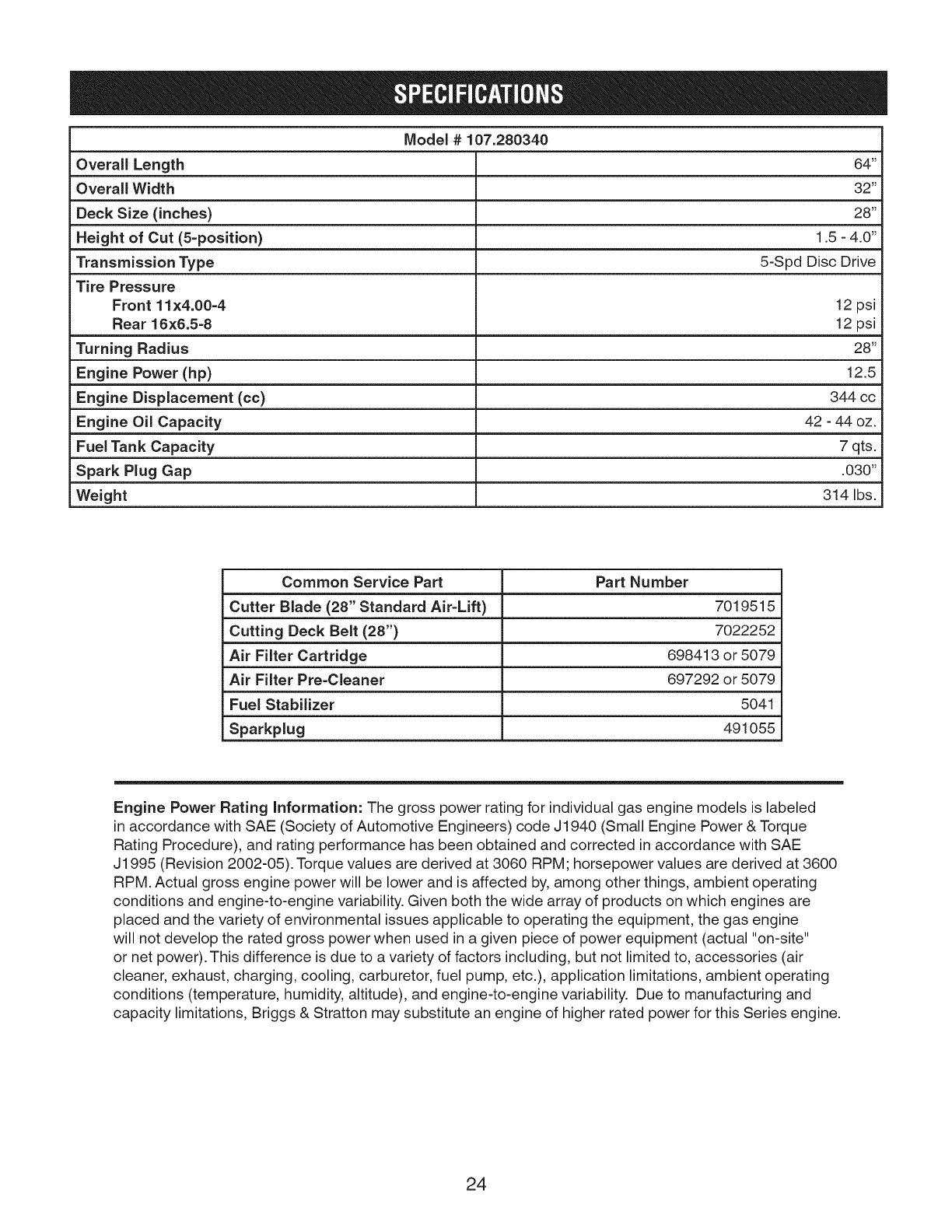
Model # 107.280340
Overall Length 64"
Overall Width 32"
Deck Size (inches) 28"
Height of Cut (5-position) 1.5 -4.0"
Transmission Type 5-Spd Disc Drive
Tire Pressure
Front 11×4.00=4 12 psi
Rear 16×6.5=8 12 psi
Turning Radius 28"
Engine Power (hp) 12.5
Engine Displacement (cc) 344 cc
Engine Oil Capacity 42 -44 oz.
Fuel Tank Capacity 7 qts.
Spark Plug Gap .030"
Weight 314 Ibs.
Common Service Part Part Number
Cutter Blade (28" Standard Air=Lift) 7019515
Cutting Deck Belt (28") 7022252
Air Filter Cartridge 698413 or 5079
Air Filter Pre=Cleaner 697292 or 5079
Fuel Stabilizer 5041
Sparkplug 491055
Engine Power Rating Information: The gross power rating for individual gas engine models is labeled
in accordance with SAE (Society of Automotive Engineers) code J1940 (Small Engine Power & Torque
Rating Procedure), and rating performance has been obtained and corrected in accordance with SAE
J1995 (Revision 2002-05). Torque values are derived at 3060 RPM; horsepower values are derived at 3600
RPM. Actual gross engine power will be lower and is affected by, among other things, ambient operating
conditions and engine-to-engine variability. Given both the wide array of products on which engines are
placed and the variety of environmental issues applicable to operating the equipment, the gas engine
will not develop the rated gross power when used in a given piece of power equipment (actual "on-site"
or net power). This difference is due to a variety of factors including, but not limited to, accessories (air
cleaner, exhaust, charging, cooling, carburetor, fuel pump, etc.), application limitations, ambient operating
conditions (temperature, humidity, altitude), and engine-to-engine variability. Due to manufacturing and
capacity limitations, Briggs & Stratton may substitute an engine of higher rated power for this Series engine.
24

RepairParts
PTS - 1
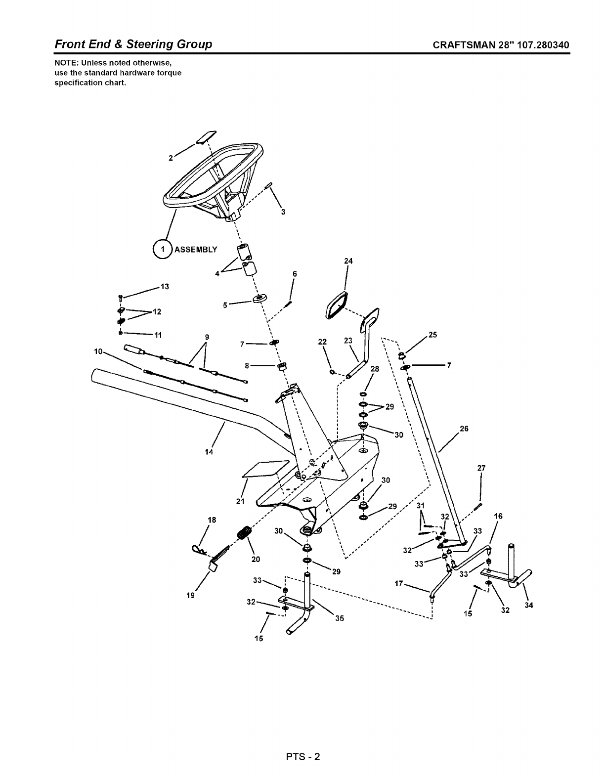
Front End & Steering Group CRAFTSMAN 28" 107.280340
NOTE: Unless noted otherwise,
use the standard hardware torque
specification chart.
21
18 -"
19
26
/
27
15
16
34
32
PTS -2
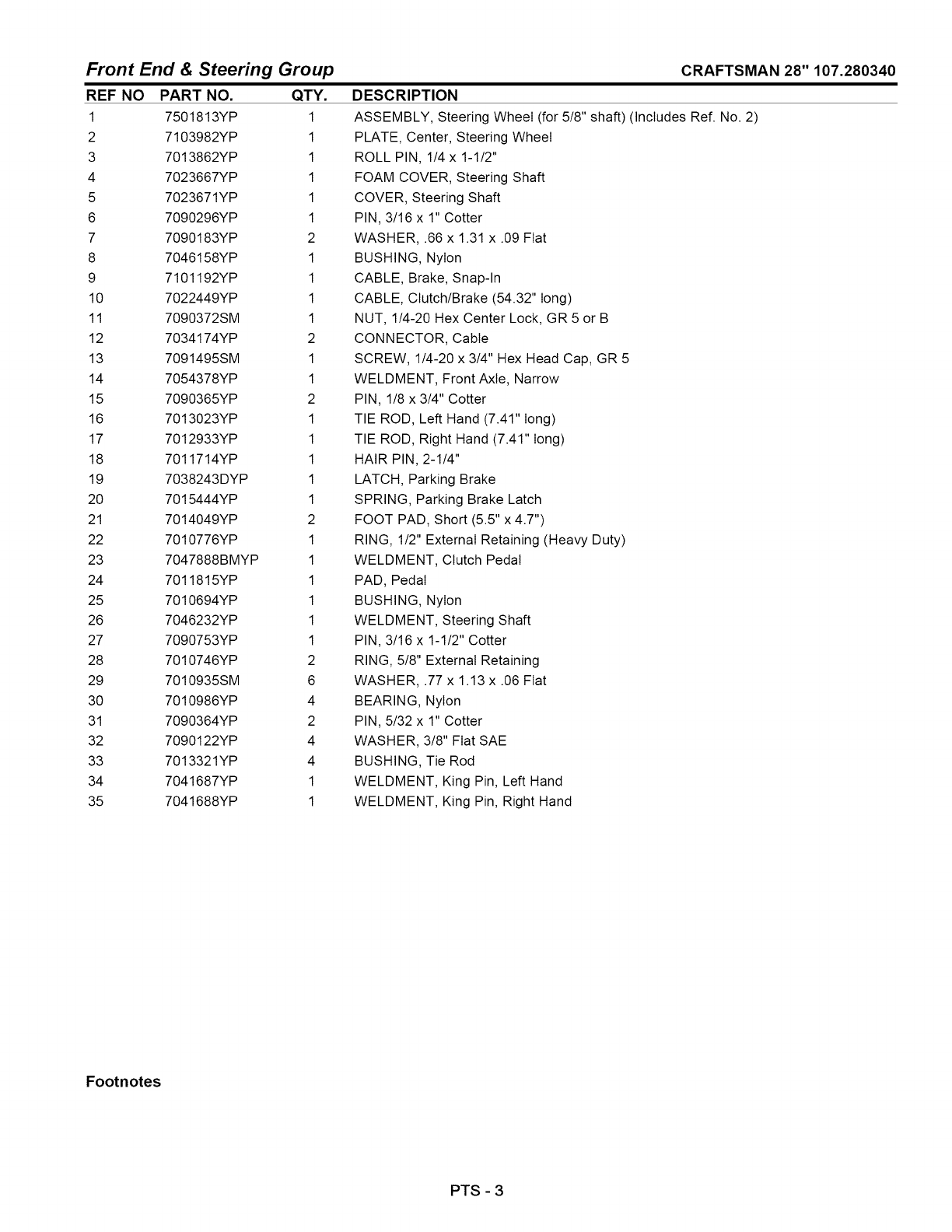
Front End & Steering Group
REF NO PART NO. QTY.
1 7501813YP 1
2 7103982YP 1
3 7013862YP 1
4 7023667YP 1
5 7023671YP 1
6 7090296YP 1
7 7090183YP 2
8 7046158YP 1
9 7101192YP 1
10 7022449YP 1
11 7090372SM 1
12 7034174YP 2
13 7091495SM 1
14 7054378YP 1
15 7090365YP 2
16 7013023YP 1
17 7012933YP 1
18 7011714YP 1
19 7038243DYP 1
20 7015444YP 1
21 7014049YP 2
22 7010776YP 1
23 7047888BMYP 1
24 7011815YP 1
25 7010694YP 1
26 7046232YP 1
27 7090753YP 1
28 7010746YP 2
29 7010935SM 6
30 7010986YP 4
31 7090364YP 2
32 7090122YP 4
33 7013321YP 4
34 7041687YP 1
35 7041688YP 1
CRAFTSMAN 28" 107.280340
DESCRIPTION
ASSEMBLY, Steering Wheel (for 5/8" shaft) (Includes Ref. No. 2)
PLATE, Center, Steering Wheel
ROLL PIN, 1/4 x 1-1/2"
FOAM COVER, Steering Shaft
COVER, Steering Shaft
PIN, 3/16 x 1" Cotter
WASHER, .66 x 1.31 x .09 Fiat
BUSHING, Nylon
CABLE, Brake, Snap-In
CABLE, Clutch/Brake (54.32" long)
NUT, 1/4-20 Hex Center Lock, GR 5 or B
CONNECTOR, Cable
SCREW, 1/4-20 x 3/4" Hex Head Cap, GR 5
WELDMENT, Front Axle, Narrow
PIN, 1/8 x 3/4" Cotter
TIE ROD, Left Hand (7.41" long)
TIE ROD, Right Hand (7.41" long)
HAIR PIN, 2-1/4"
LATCH, Parking Brake
SPRING, Parking Brake Latch
FOOT PAD, Short (5.5" x 4.7")
RING, 1/2" External Retaining (Heavy Duty)
WELDMENT, Clutch Pedal
PAD, Pedal
BUSHING, Nylon
WELDMENT, Steering Shaft
PIN, 3/16 x 1-1/2" Cotter
RING, 5/8" External Retaining
WASHER, .77 x 1.13 x .06 Fiat
BEARING, Nylon
PIN, 5/32 x 1" Cotter
WASHER, 3/8" Fiat SAE
BUSHING, Tie Rod
WELDMENT, King Pin, Left Hand
WELDMENT, King Pin, Right Hand
Footnotes
PTS - 3
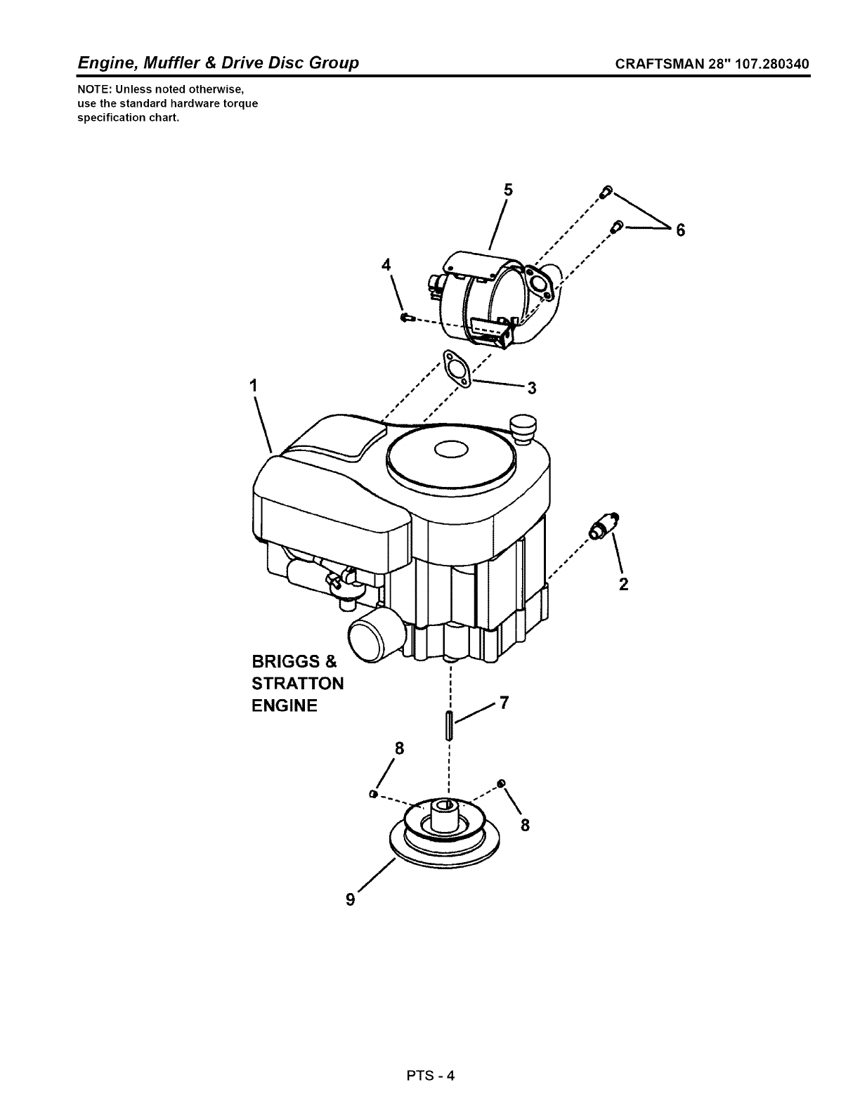
Engine, Muffler & Drive Disc Group CRAFTSMAN 28" 107.280340
NOTE: Unless noted otherwise,
use the standard hardware torque
specification chart.
4\
5
!
3
2
BRIGGS &
STRATTON
ENGINE 7
8
/
9
PTS -4

Engine, Muffler & Drive Disc Group
REF NO PART NO. QTY.
1 219977-0130-B1 1
2 7027972SM 1
3 7015352SM 1
4 7090362YP 2
5 7074453YP 1
6 7091738SM 2
7 7010210SM 1
8 7090132YP 2
9 7072658YP 1
10 7091576SM 1
CRAFTSMAN 28" 107.280340
DESCRIPTION
* ENGINE, 12.5HP Briggs Intek OHV, E. S. No Recoil electric start
ASSEMBLY, Oil Valve
GASKET, Exhaust
SCREW, 1/4-20 x 5/8" Hex Washer Head Self-Tap
MUFFLER, w/Heat Shield (Briggs 11 thru 17.5HP)
SET SCREW, 5/16-18 x 3/4" Socket Head, GR8
KEY, 1/4" Square x 2" Long
SET SCREW, HRSS, 3/8-16 x 3/8"
WELDMENT, 5.75" O.D. Drive Disc
NUT, 1/4-20 Hex, GR 5 or B (not shown) (attaches to starter terminal)
Footnotes
Note: * Purchase engine parts from engine manufacture dealer.
PTS -5
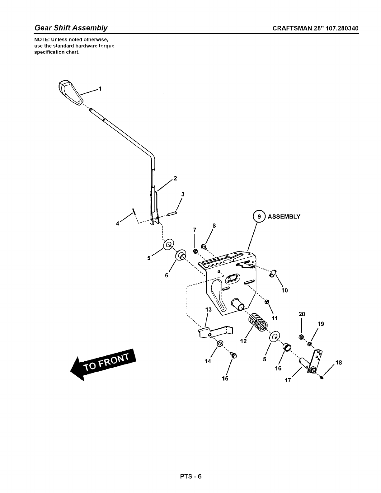
Gear Shift Assembly CRAFTSMAN 28" 107.280340
NOTE: Unless noted otherwise,
use the standard hardware torque
specification chart.
2
3
/
8(_ ASSEMBLY
\11
5
16
10
PTS -6
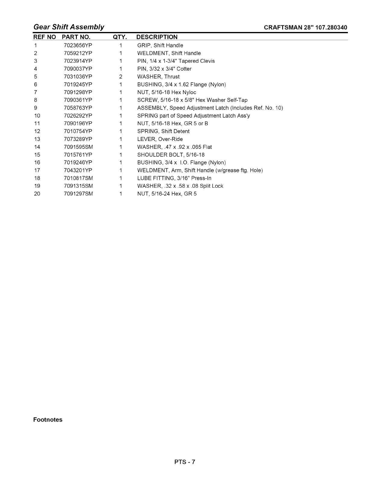
Gear Shift Assembly
REF NO PART NO. QTY.
1 7023656YP 1
2 7059212YP 1
3 7023914YP 1
4 7090037YP 1
5 7031036YP 2
6 7019245YP 1
7 7091298YP 1
8 7090361YP 1
9 7058763YP 1
10 7026292YP 1
11 7090196YP 1
12 7010754YP 1
13 7073289YP 1
14 7091595SM 1
15 7015761YP 1
16 7019246YP 1
17 7043201YP 1
18 7010817SM 1
19 7091315SM 1
20 7091297SM 1
CRAFTSMAN 28" 107.280340
DESCRIPTION
GRIP, Shift Handle
WELDMENT, Shift Handle
PIN, 1/4 x 1-3/4" Tapered Clevis
PIN, 3/32 x 3/4" Cotter
WASHER, Thrust
BUSHING, 3/4 x 1.62 Flange (Nylon)
NUT, 5/16-18 Hex NyIoc
SCREW, 5/16-18 x 5/8" Hex Washer Self-Tap
ASSEMBLY, Speed Adjustment Latch (Includes Ref. No. 10)
SPRING part of Speed Adjustment Latch Ass'y
NUT, 5/16-18 Hex, GR 5 or B
SPRING, Shift Detent
LEVER, Over-Ride
WASHER, .47 x .92 x .065 Fiat
SHOULDER BOLT, 5/16-18
BUSHING, 3/4 x I.O. Flange (Nylon)
WELDMENT, Arm, Shift Handle (w/grease ftg. Hole)
LUBE FITTING, 3/16" Press-In
WASHER, .32 x .58 x .08 Split Lock
NUT, 5/16-24 Hex, GR 5
Footnotes
PTS - 7
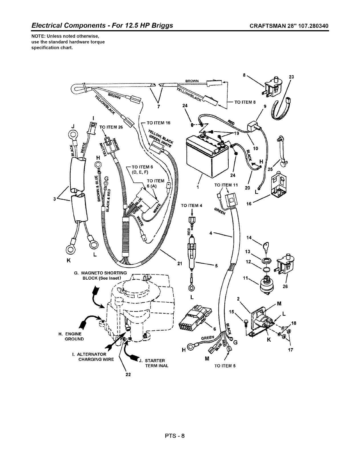
Electrical Components - For 12.5 HP Briggs CRAFTSMAN 28" 107.280340
NOTE: Unless noted otherwise,
use the standard hardware torque
specification chart.
K
I 1
GROUND ,_
I. ALTERNATOR
CHARGING WIRE
G. MAGNETO SHORTING -_--,,_---4
BLOCK (See Inset) ..,_j_., _ _ *'_
J. STARTER
TERM INAL
\
TO ITEM 16 k
24
21
H
M
8 23
TO ITEM 8 9
TO ITEM 5
22
PTS -8
Electrical Components - For 12.5 HP Briggs
REF NO
1
2
3
4
5
6
7
8
9
10
11
12
13
14
15
16
17
18
19
2O
21
22
23
24
25
26
CRAFTSMAN 28" 107.280340
PART NO.
7075373YP
7075671YP
7022788YP
7073715YP
7016168YP
7016169YP
7028606YP
7028386YP
7018524YP
7012444YP
7019326YP
7073797YP
7090880YP
7015438YP
7011138YP
7090539YP
7022886YP
7091576SM
7090053SM
7027172YP
7028027YP
7028607YP
7091576SM
7012080SM
7090372SM
7014451YP
7023354YP
QTY.
1
1
1
1
1
1
1
1
1
1
1
1
1
1
1
3
1
4
2
2
1
1
1
2
2
1
1
DESCRIPTION
BATTERY, 12V 140CCA L Terminal
SOLENOID, Super-Trombetta
HARNESS, Starter Wiring (Briggs Engines)
HARNESS, Ignition Wiring (Briggs Engines)
HOLDER, Fuse (Includes Fuse)
FUSE, 10 Amp (Not shown)
INTERLOCK MODULE, Briggs
HARNESS (Deck Interlock Wiring)
SWITCH, Deck Interlock (NO)
COVER, Battery Cable
WIRE, Positive (Red, 17" long)
SWITCH, Ignition, 4 Terminal, Indak
WASHER, 5/8" Internal Tooth Lock
NUT, 5/8-32 Hex
IGNITION KEY, Pair
SCREW, 1/4-20 x 1/2" Hex Washer Self-Tap
SWITCH, Operator Presence Control (OPC) Traction (NC/NO)
NUT, 1/4-20 Hex, GR 5 or B
WASHER, 1/4" Internal Tooth Lock
SCREW, 1/4-20 x 5/8" Hex Head Cap. GR 5
WIRE, Negative, Black (15" long)
HARNESS, Operator Presence Control (OPC) Wire
NUT, 1/4-20 Hex, GR 5 or B
CABLE TIE, 7"
NUT, 1/4-20 Hex Center Lock, GR 5 or B
CABLE TIE
SWITCH, Seat (NC)
Footnotes
PTS - 9
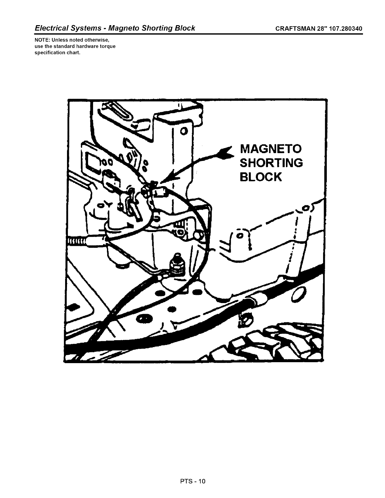
Electrical Systems -Magneto Shorting Block CRAFTSMAN 28" 107.280340
NOTE: Unless noted otherwise,
use the standard hardware torque
specification chart.
O
MAGNETO
SHORTING
BLOCK
i
PTS -10

Electrical Systems -Magneto Shorting Block CRAFTSMAN 28" 107.280340
REF NO PART NO. QTY. DESCRIPTION
.... View shows engine magneto ground connection on throttle plate
Footnotes
PTS -11
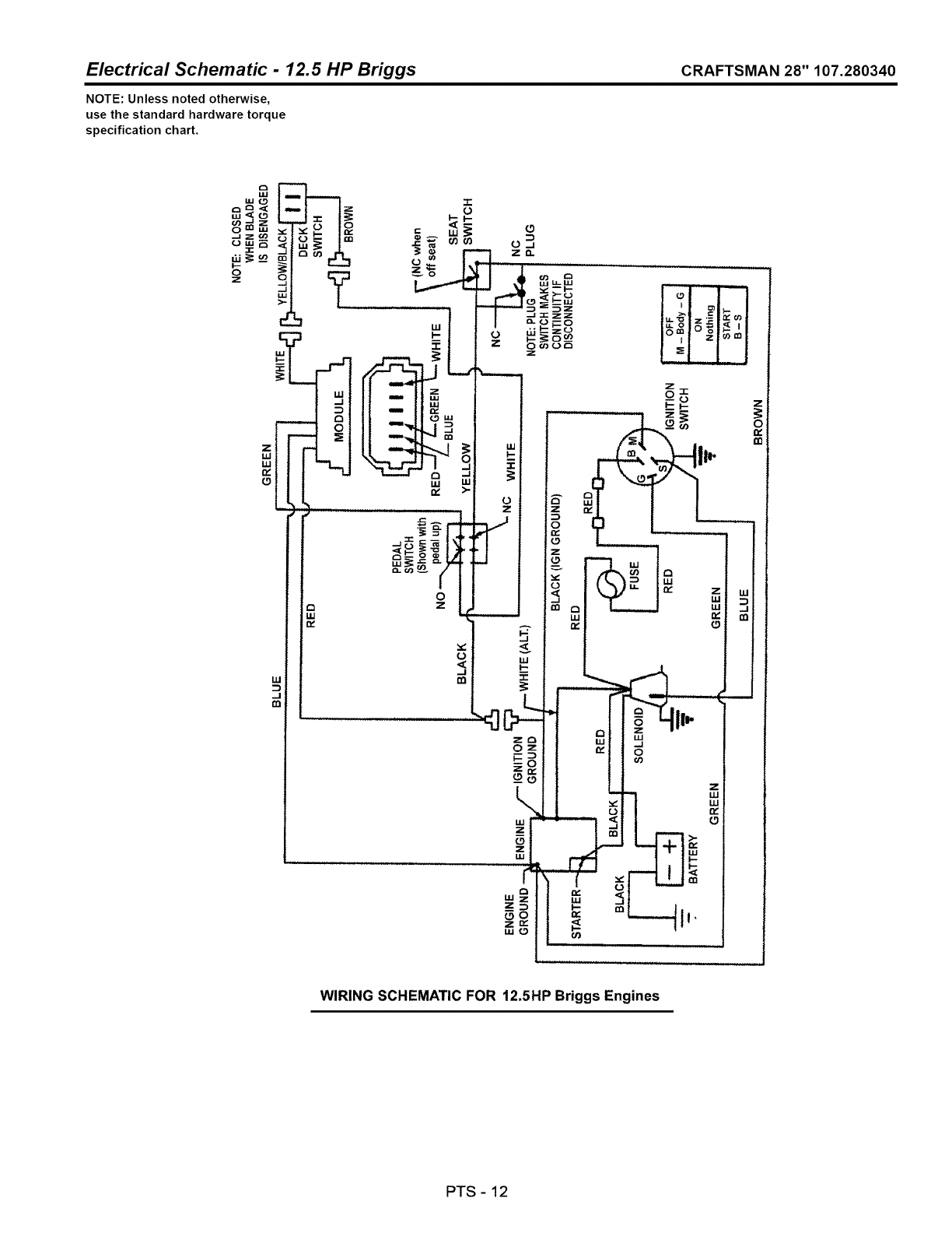
Electrical Schematic - 12.5 HP Briggs CRAFTSMAN 28" 107.280340
NOTE: Unless noted otherwise,
use the standard hardware torque
specification chart.
°E
8=
i
o
>-
Z
ILl
LU
n,"
L_
_= I=
Y
h
IIJI
LU
w'
WIRING SCHEMATIC FOR 12.5HP Briggs Engines
PTS -12

Electrical Schematic - 12.5 HP Briggs
REF NO PART NO, QTY, DESCRIPTION
..... Electrical Schematic
CRAFTSMAN 28" 107.280340
Footnotes
PTS -13
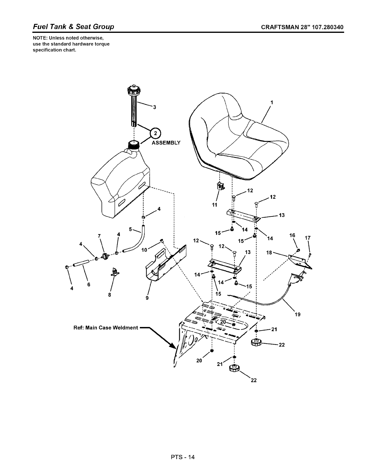
Fuel Tank & Seat Group CRAFTSMAN 28" 107.280340
NOTE: Unless noted otherwise,
use the standard hardware torque
specification chart.
:"_SASSEMBLY
1
/
19
PTS -14
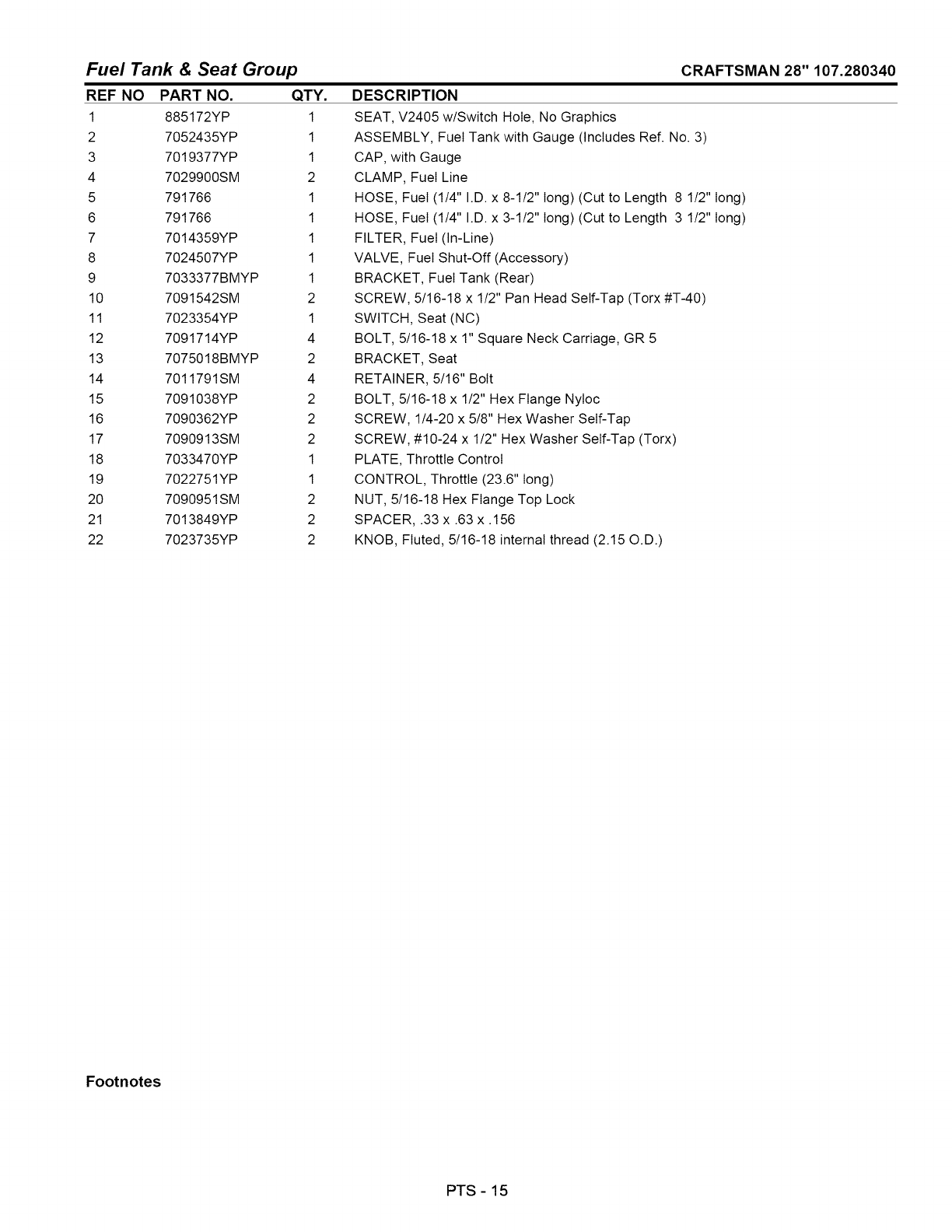
Fuel Tank & Seat Group
REF NO PART NO. QTY.
1 885172YP 1
2 7052435YP 1
3 7019377YP 1
4 7029900SM 2
5 791766 1
6 791766 1
7 7014359YP 1
8 7024507YP 1
9 7033377BMYP 1
10 7091542SM 2
11 7023354YP 1
12 7091714YP 4
13 7075018BMYP 2
14 7011791SM 4
15 7091038YP 2
16 7090362YP 2
17 7090913SM 2
18 7033470YP 1
19 7022751YP 1
20 7090951SM 2
21 7013849YP 2
22 7023735YP 2
CRAFTSMAN 28" 107.280340
DESCRIPTION
SEAT, V2405 w/Switch Hole, No Graphics
ASSEMBLY, Fuel Tank with Gauge (Includes Ref. No. 3)
CAP, with Gauge
CLAMP, Fuel Line
HOSE, Fuel (1/4" I.D. x 8-1/2" long) (Cut to Length 8 1/2" long)
HOSE, Fuel (1/4" I.D. x 3-1/2" long) (Cut to Length 3 1/2" long)
FILTER, Fuel (In-Line)
VALVE, Fuel Shut-Off (Accessory)
BRACKET, Fuel Tank (Rear)
SCREW, 5/16-18 x 1/2" Pan Head Self-Tap (Torx #T-40)
SWITCH, Seat (NC)
BOLT, 5/16-18 x 1" Square Neck Carriage, GR 5
BRACKET, Seat
RETAINER, 5/16" Bolt
BOLT, 5/16-18 x 1/2" Hex Flange Nyloc
SCREW, 1/4-20 x 5/8" Hex Washer Self-Tap
SCREW, #10-24 x 1/2" Hex Washer Self-Tap (Torx)
PLATE, Throttle Control
CONTROL, Throttle (23.6" long)
NUT, 5/16-18 Hex Flange Top Lock
SPACER, .33 x .63 x. 156
KNOB, Fluted, 5/16-18 internal thread (2.15 O.D.)
Footnotes
PTS -15
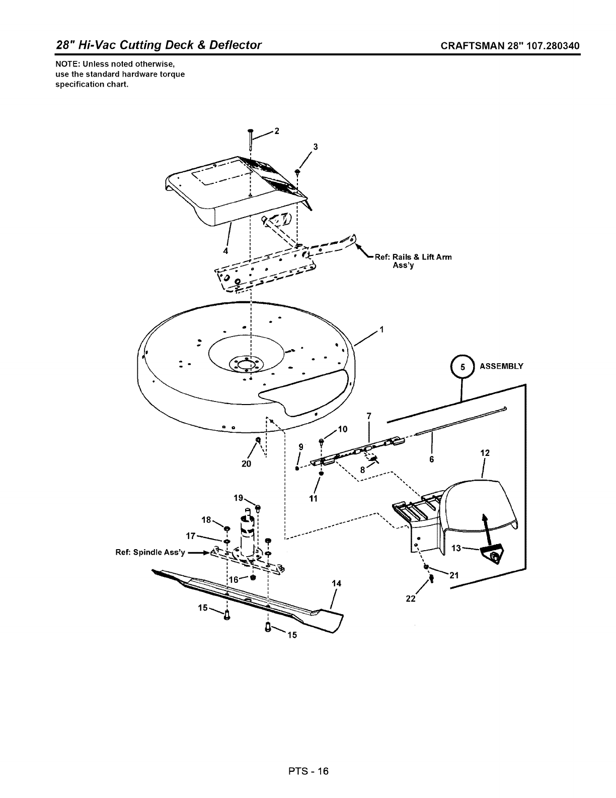
28" Hi-Vac Cutting Deck & Deflector CRAFTSMAN 28" 107.280340
NOTE: Unless noted otherwise,
use the standard hardware torque
specification chart.
_.....I 2 3
4,....-._-----*.., .......-.. %.
'--"_""Z, " q','_ "--Ref"
.,..,,,_.,.. • ;._)
t
Rails & Lift Arm
Ass'y
20
22
PTS -16

28" Hi-Vac Cutting Deck & Deflector
REF NO
1
2
3
4
5
6
7
8
9
10
11
12
13
14
15
16
17
18
19
2O
21
22
CRAFTSMAN 28" 107.280340
PART NO.
7061970YP
7091015YP
7091016YP
7073434YP
7500484YP
7026234YP
7300886BMYP
7016341YP
7026483YP
7091811SM
7091070YP
7026233YP
7013010SM
7600103YP
7090491YP
7090613YP
7090509YP
7091939YP
7090612YP
7091508SM
7091296YP
7090492YP
QTY.
1
2
4
1
1
1
1
1
2
3
2
1
1
1
2
9
2
2
3
2
2
2
DESCRIPTION
DECK, 28" Replacement (Painted deck w/decals & wheel bracket fasteners)
SCREW, 1/4-20 x 3-1/2" Hex Head w/Free Spinning Washer
SCREW, 1/4-20 x 5/8" Hex Head w/Free Spinning Washer
COVER, Spindle
ASSEMBLY, Discharge Deflector, 28" without decal (Includes Ref. Nos. 6, 7, 8, 9 & 12)
PIN, Hinge
HINGE, Deflector (Deck side)
SPRING, Hinge
PUSH NUT, 1/4"
BOLT, 5/16-18 x 5/8" Hex Flange Lock, GR 5
NUT, 5/16-18 Hex Flange Lock, GR 5
DEFLECTOR, Discharge, 28"
DECAL, Danger, (Cut Finger)
BLADE, Replacement Kit, 28"
SCREW, 1/2-20 x 1-1/4" Hex Head Cap, GR 5
NUT, 3/8-16 Hex Flange Lock
WASHER, 1/2" Internal Tooth Lock
NUT, 1/2-20 Hex, GR 5 or B
BOLT, 3/8-16 x 3/4" Hex Flange Lock
BOLT, 5/16-18 x 3/4" Short Neck Carriage, GR 5
WASHER, 5/16" Fiat
NUT, 5/16-18 Wing
Footnotes
PTS - 17
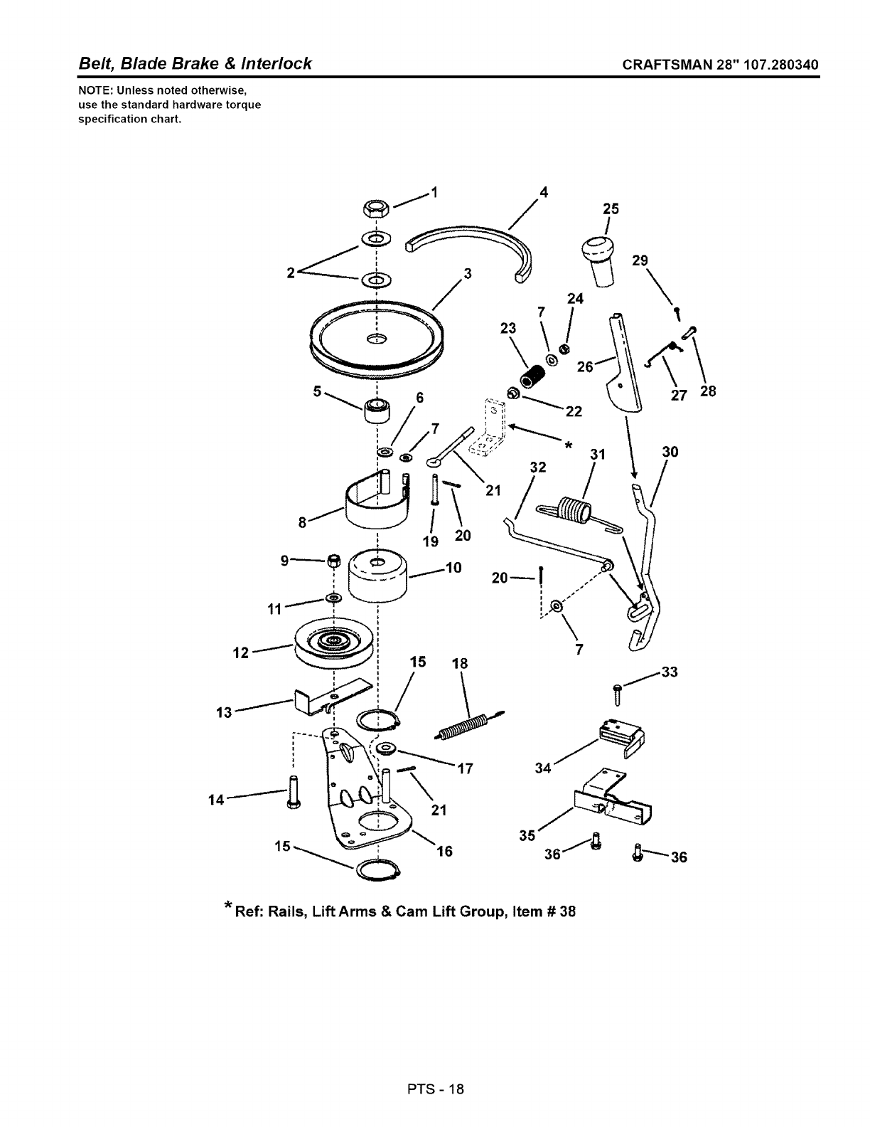
Belt, Blade Brake & Interlock CRAFTSMAN 28" 107.280340
NOTE: Unless noted otherwise,
use the standard hardware torque
specification chart.
29\
27
30
/
Ref: Rails, Lift Arms & Cam Lift Group, Item # 38
28
PTS -18
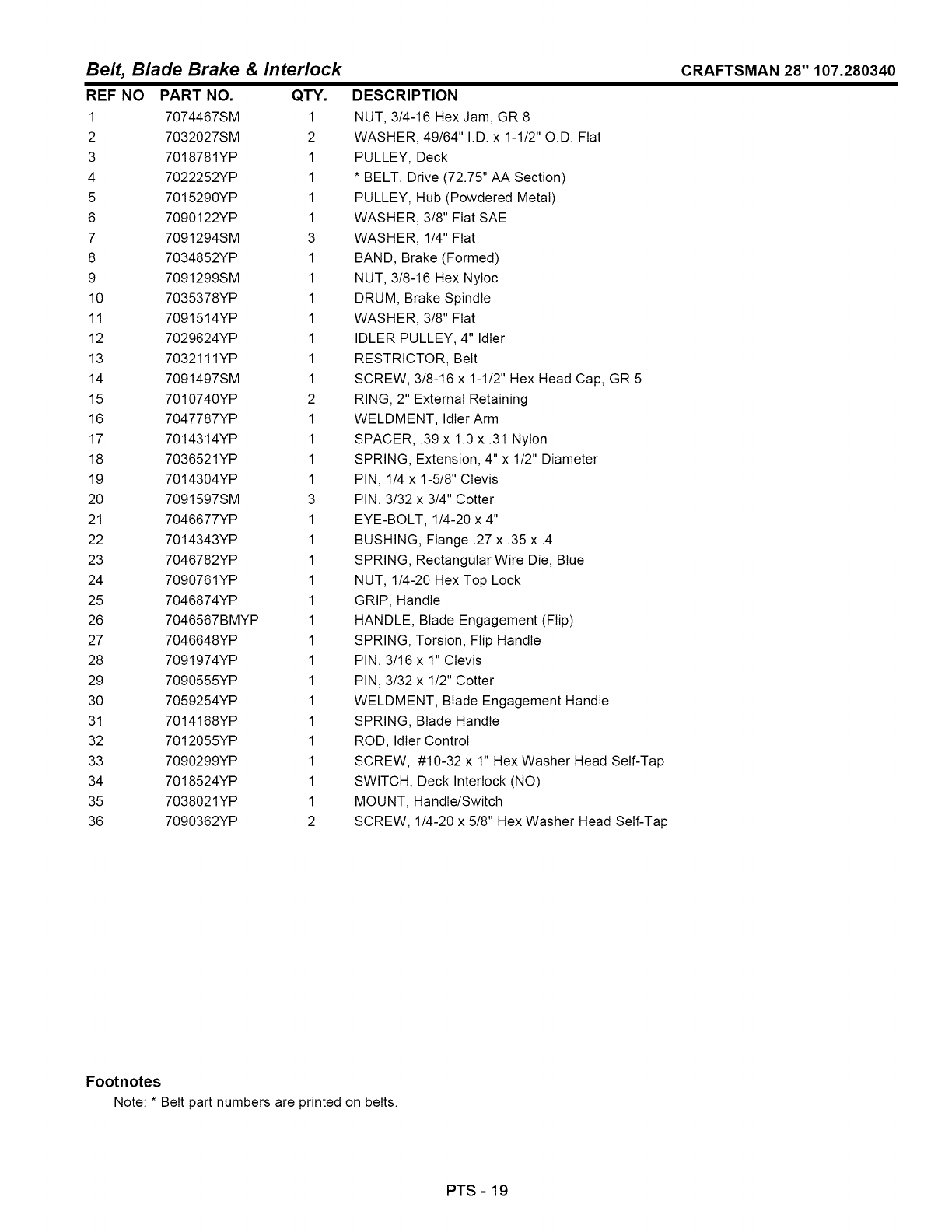
Bel_ Blade Brake & Interlock
REF NO PART NO. QTY.
1 7074467SM 1
2 7032027SM 2
3 7018781YP 1
4 7022252YP 1
5 7015290YP 1
6 7090122YP 1
7 7091294SM 3
8 7034852YP 1
9 7091299SM 1
10 7035378YP 1
11 7091514YP 1
12 7029624YP 1
13 7032111YP 1
14 7091497SM 1
15 7010740YP 2
16 7047787YP 1
17 7014314YP 1
18 7036521YP 1
19 7014304YP 1
20 7091597SM 3
21 7046677YP 1
22 7014343YP 1
23 7046782YP 1
24 7090761YP 1
25 7046874YP 1
26 7046567BMYP 1
27 7046648YP 1
28 7091974YP 1
29 7090555YP 1
30 7059254YP 1
31 7014168YP 1
32 7012055YP 1
33 7090299YP 1
34 7018524YP 1
35 7038021YP 1
36 7090362YP 2
DESCRIPTION
NUT, 3/4-16 Hex Jam, GR 8
WASHER, 49/64" I.D. x 1-1/2" O.D. Fiat
PULLEY, Deck
* BELT, Drive (72.75" AA Section)
PULLEY, Hub (Powdered Metal)
WASHER, 3/8" Fiat SAE
WASHER, 1/4" Fiat
BAND, Brake (Formed)
NUT, 3/8-16 Hex NyIoc
DRUM, Brake Spindle
WASHER, 3/8" Fiat
IDLER PULLEY, 4" Idler
RESTRICTOR, Belt
SCREW, 3/8-16 x 1-1/2" Hex Head Cap, GR 5
RING, 2" External Retaining
WELDMENT, Idler Arm
SPACER, .39 x 1.0 x .31 Nylon
SPRING, Extension, 4" x 1/2" Diameter
PIN, 1/4 x 1-5/8" Clevis
PIN, 3/32 x 3/4" Cotter
EYE-BOLT, 1/4-20 x 4"
BUSHING, Flange .27 x .35 x .4
SPRING, Rectangular Wire Die, Blue
NUT, 1/4-20 Hex Top Lock
GRIP, Handle
HANDLE, Blade Engagement (Flip)
SPRING, Torsion, Flip Handle
PIN, 3/16 x 1" Clevis
PIN, 3/32 x 1/2" Cotter
WELDMENT, Blade Engagement Handle
SPRING, Blade Handle
ROD, Idler Control
SCREW, #10-32 x 1" Hex Washer Head Self-Tap
SWITCH, Deck Interlock (NO)
MOUNT, Handle/Switch
SCREW, 1/4-20 x 5/8" Hex Washer Head Self-Tap
CRAFTSMAN 28" 107.280340
Footnotes
Note: * Belt part numbers are printed on belts.
PTS - 19
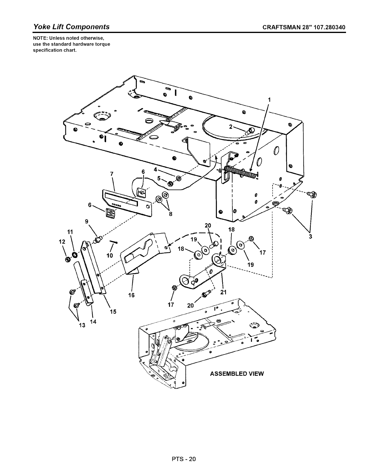
Yoke Lift Components CRAFTSMAN 28" 107.280340
NOTE: Unless noted otherwise,
use the standard hardware torque
specification chart.
7
/
16
8
20
19
18_
18
17
"_ 21
//_
17 20
ASSEMBLED VIEW
PTS -20
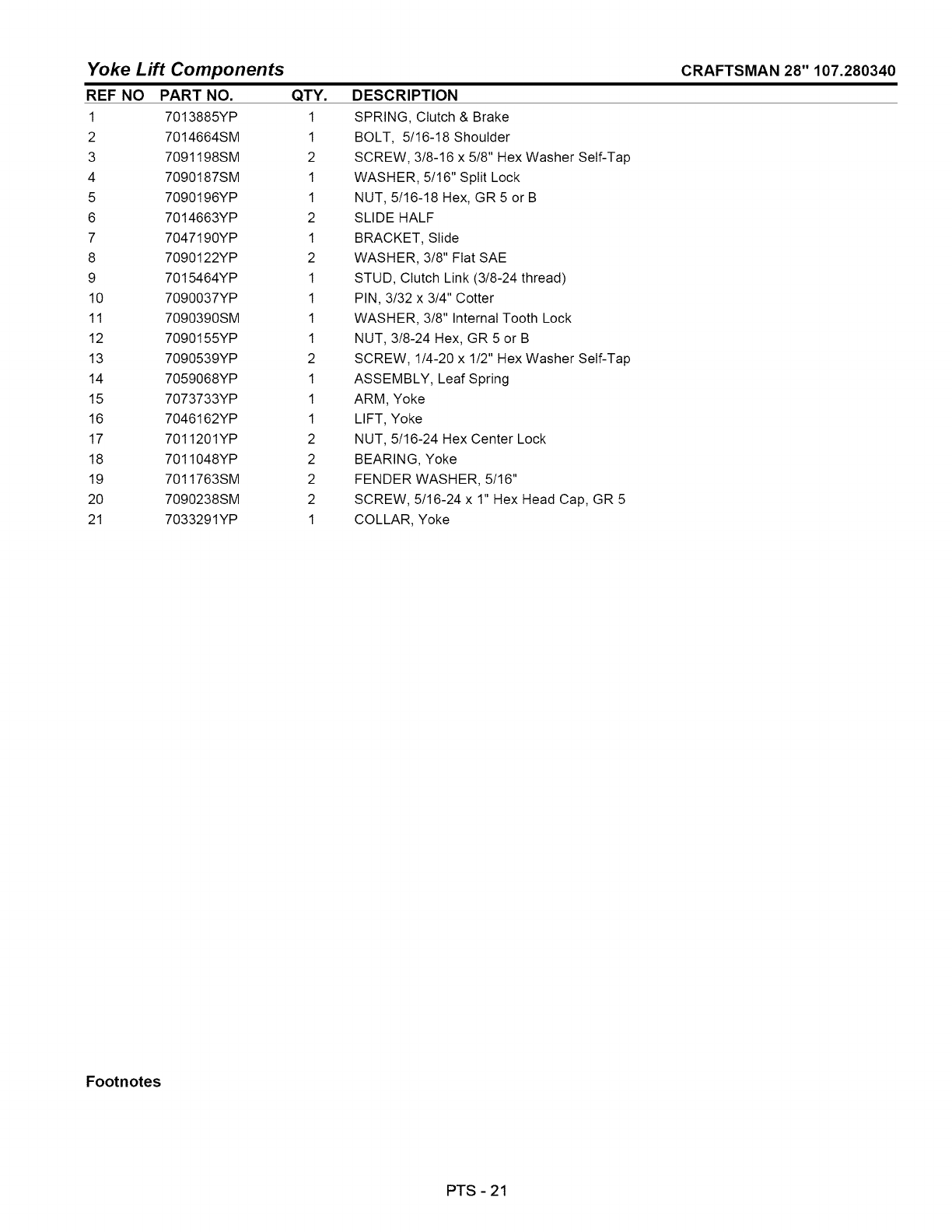
Yoke Lift Components
REF NO PART NO. QTY.
1 7013885YP 1
2 7014664SM 1
3 7091198SM 2
4 7090187SM 1
5 7090196YP 1
6 7014663YP 2
7 7047190YP 1
8 7090122YP 2
9 7015464YP 1
10 7090037YP 1
11 7090390SM 1
12 7090155YP 1
13 7090539YP 2
14 7059068YP 1
15 7073733YP 1
16 7046162YP 1
17 7011201YP 2
18 7011048YP 2
19 7011763SM 2
20 7090238SM 2
21 7033291YP 1
DESCRIPTION
SPRING, Clutch & Brake
BOLT, 5/16-18 Shoulder
SCREW, 3/8-16 x 5/8" Hex Washer Self-Tap
WASHER, 5/16" Split Lock
NUT, 5/16-18 Hex, GR 5 or B
SLIDE HALF
BRACKET, Slide
WASHER, 3/8" Fiat SAE
STUD, Clutch Link (3/8-24 thread)
PIN, 3/32 x 3/4" Cotter
WASHER, 3/8" Internal Tooth Lock
NUT, 3/8-24 Hex, GR 5 or B
SCREW, 1/4-20 x 1/2" Hex Washer Self-Tap
ASSEMBLY, Leaf Spring
ARM, Yoke
LIFT, Yoke
NUT, 5/16-24 Hex Center Lock
BEARING, Yoke
FENDER WASHER, 5/16"
SCREW, 5/16-24 x 1" Hex Head Cap, GR 5
COLLAR, Yoke
CRAFTSMAN 28" 107.280340
Footnotes
PTS -21
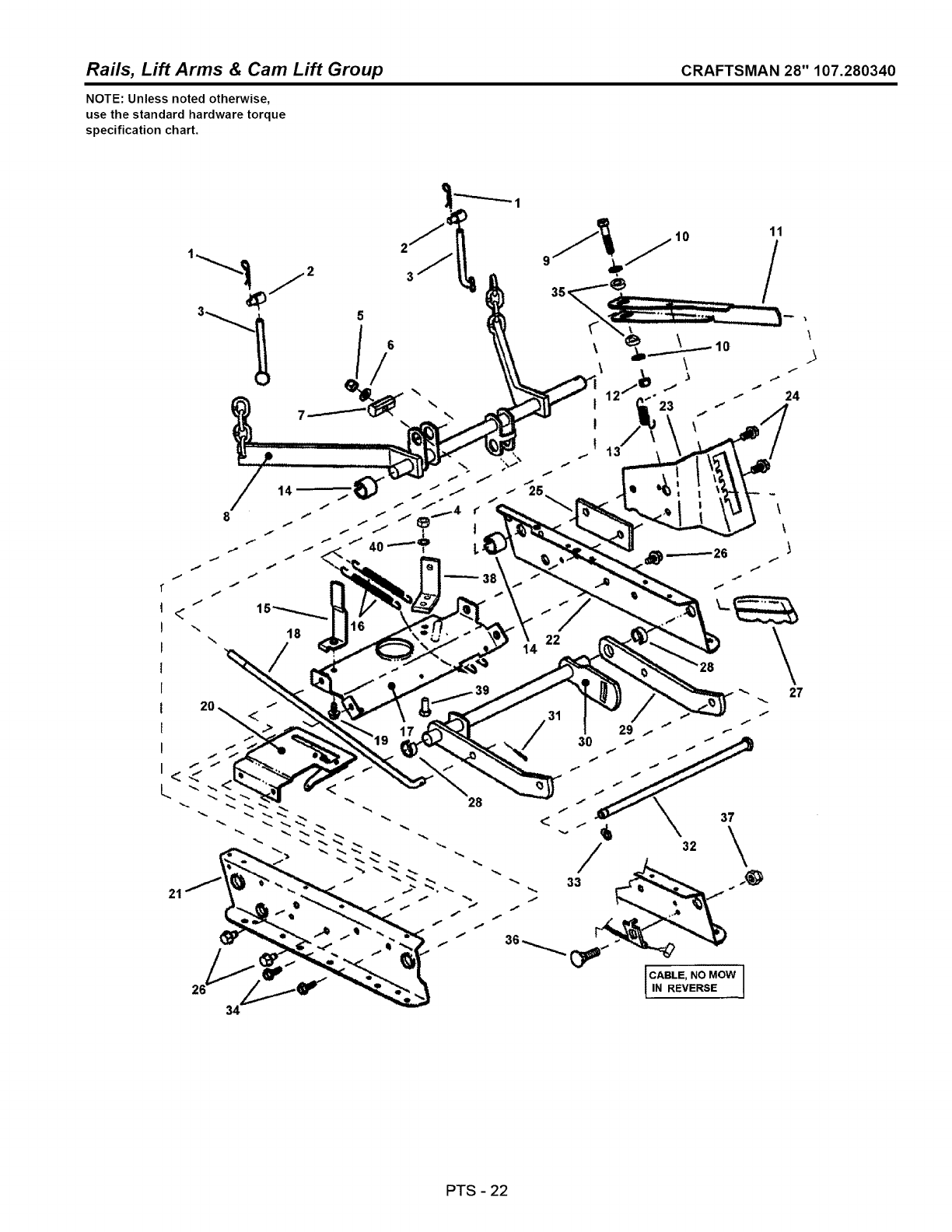
Rails, Lift Arms & Cam Lift Group CRAFTSMAN 28" 107.280340
NOTE: Unless noted otherwise,
use the standard hardware torque
specification chart.
10
11
\
>
\27
PTS -22
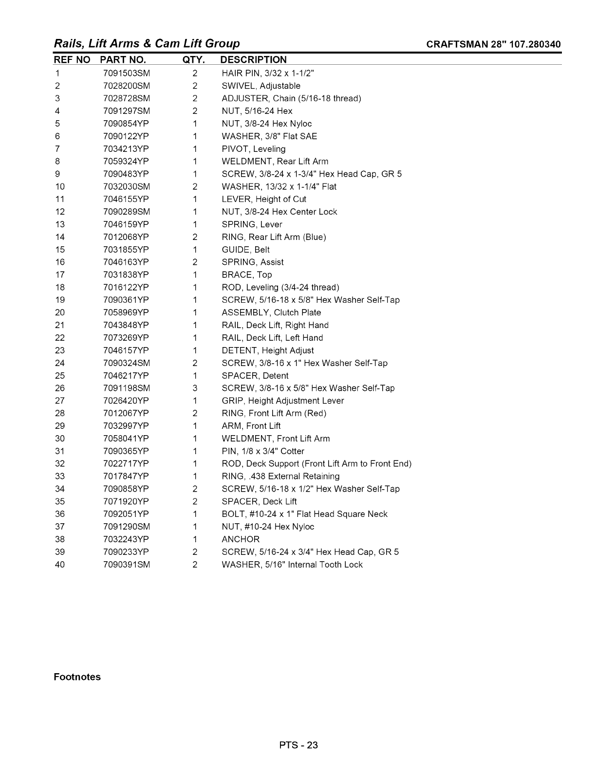
Rails, Lift Arms & Cam Lift Group CRAFTSMAN 28" 107.280340
REF NO PART NO.
1 7091503SM
2 7028200SM
3 7028728SM
4 7091297SM
5 7090854YP
6 7090122YP
7 7034213YP
8 7059324YP
9 7090483YP
10 7032030SM
11 7046155YP
12 7090289SM
13 7046159YP
14 7012068YP
15 7031855YP
16 7046163YP
17 7031838YP
18 7016122YP
19 7090361YP
20 7058969YP
21 7043848YP
22 7073269YP
23 7046157YP
24 7090324SM
25 7046217YP
26 7091198SM
27 7026420YP
28 7012067YP
29 7032997YP
30 7058041YP
31 7090365YP
32 7022717YP
33 7017847YP
34 7090858YP
35 7071920YP
36 7092051YP
37 7091290SM
38 7032243YP
39 7090233YP
40 7090391SM
QTY.
2
2
2
2
1
1
1
1
1
2
1
1
1
2
1
2
1
1
1
1
1
1
1
2
1
3
1
2
1
1
1
1
1
2
2
1
1
1
2
2
DESCRIPTION
HAIR PIN, 3/32 x 1-1/2"
SWIVEL, Adjustable
ADJUSTER, Chain (5/16-18 thread)
NUT, 5/16-24 Hex
NUT, 3/8-24 Hex NyIoc
WASHER, 3/8" Fiat SAE
PIVOT, LeveIing
WELDMENT, Rear Lift Arm
SCREW, 3/8-24 x 1-3/4" Hex Head Cap, GR 5
WASHER, 13/32 x 1-1/4" Fiat
LEVER, Height of Cut
NUT, 3/8-24 Hex Center Lock
SPRING, Lever
RING, Rear Lift Arm (Blue)
GUIDE, Belt
SPRING, Assist
BRACE, Top
ROD, LeveIing (3/4-24 thread)
SCREW, 5/16-18 x 5/8" Hex Washer Self-Tap
ASSEMBLY, Clutch Plate
RAIL, Deck Lift, Right Hand
RAIL, Deck Lift, Left Hand
DETENT, Height Adjust
SCREW, 3/8-16 x 1" Hex Washer Self-Tap
SPACER, Detent
SCREW, 3/8-16 x 5/8" Hex Washer Self-Tap
GRIP, Height Adjustment Lever
RING, Front Lift Arm (Red)
ARM, Front Lift
WELDMENT, Front Lift Arm
PIN, 1/8 x 3/4" Cotter
ROD, Deck Support (Front Lift Arm to Front End)
RING, .438 External Retaining
SCREW, 5/16-18 x 1/2" Hex Washer Self-Tap
SPACER, Deck Lift
BOLT, #10-24 x 1" Fiat Head Square Neck
NUT, #10-24 Hex Nyloc
ANCHOR
SCREW, 5/16-24 x 3/4" Hex Head Cap, GR 5
WASHER, 5/16" Internal Tooth Lock
Footnotes
PTS - 23
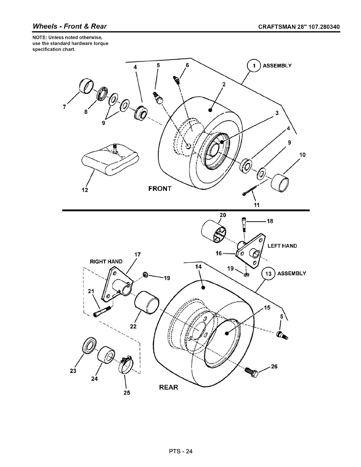
Wheels -Front & Rear CRAFTSMAN 28" 107.280340
NOTE: Unless noted otherwise,
use the standard hardware torque
specification chart.
/
8
45
/
\
9
12 FRONT
REAR
14
/
PTS -24
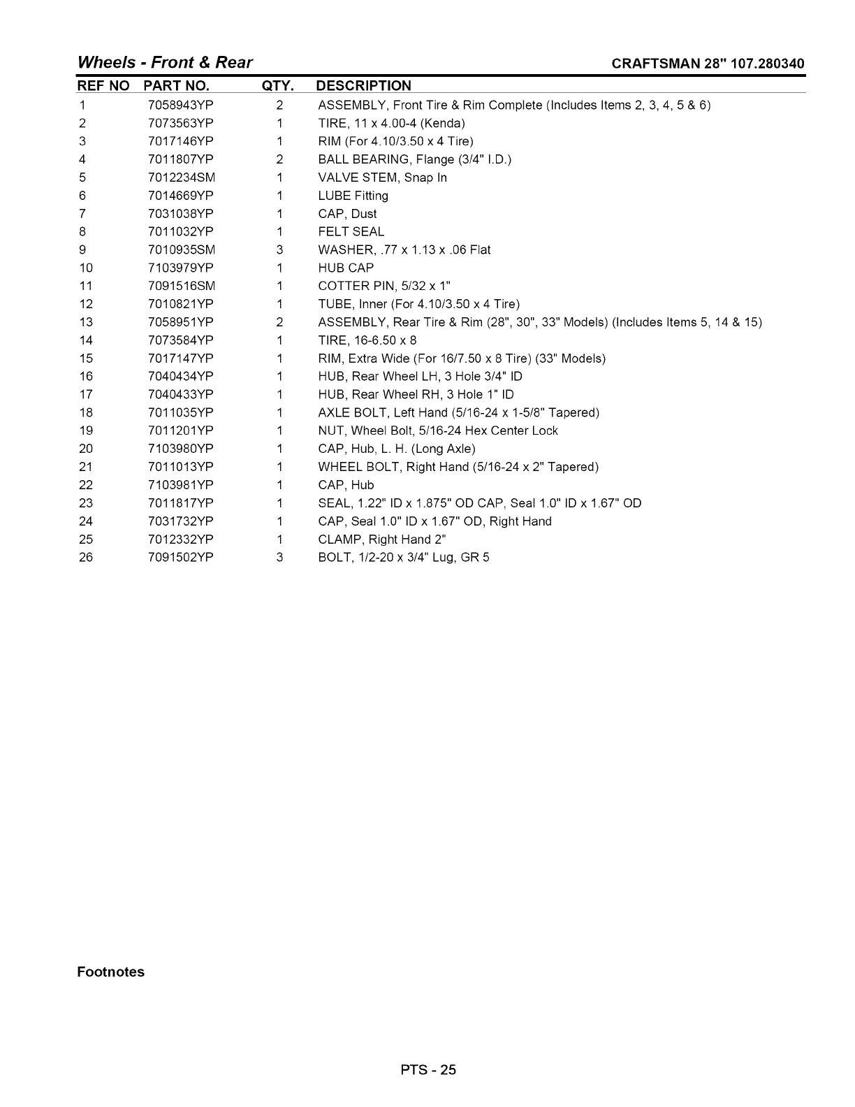
Wheels -Front & Rear
REF NO PART NO. QTY.
1 7058943YP 2
2 7073563YP 1
3 7017146YP 1
4 7011807YP 2
5 7012234SM 1
6 7014669YP 1
7 7031038YP 1
8 7011032YP 1
9 7010935SM 3
10 7103979YP 1
11 7091516SM 1
12 7010821YP 1
13 7058951YP 2
14 7073584YP 1
15 7017147YP 1
16 7040434YP 1
17 7040433YP 1
18 7011035YP 1
19 7011201YP 1
20 7103980YP 1
21 7011013YP 1
22 7103981YP 1
23 7011817YP 1
24 7031732YP 1
25 7012332YP 1
26 7091502YP 3
CRAFTSMAN 28" 107.280340
DESCRIPTION
ASSEMBLY, Front Tire & Rim Complete (Includes Items 2, 3, 4, 5 & 6)
TIRE, 11 x 4.00-4 (Kenda)
RIM (For 4.10/3.50 x 4 Tire)
BALL BEARING, Flange (3/4" I.D.)
VALVE STEM, Snap In
LUBE Fitting
CAP, Dust
FELT SEAL
WASHER, .77 x 1.13 x .06 Fiat
HUB CAP
COTTER PIN, 5/32 x 1"
TUBE, Inner (For 4.10/3.50 x 4 Tire)
ASSEMBLY, Rear Tire & Rim (28", 30", 33" Models) (Includes Items 5, 14 & 15)
TIRE, 16-6.50 x 8
RIM, Extra Wide (For 16/7.50 x 8 Tire) (33" Models)
HUB, Rear Wheel LH, 3 Hole 3/4" ID
HUB, Rear Wheel RH, 3 Hole 1" ID
AXLE BOLT, Left Hand (5/16-24 x 1-5/8" Tapered)
NUT, Wheel Bolt, 5/16-24 Hex Center Lock
CAP, Hub, L. H. (Long Axle)
WHEEL BOLT, Right Hand (5/16-24 x 2" Tapered)
CAP, Hub
SEAL, 1.22" ID x 1.875" OD CAP, Seal 1.0" ID x 1.67" OD
CAP, Seal 1.0" ID x 1.67" OD, Right Hand
CLAMP, Right Hand 2"
BOLT, 1/2-20 x 3/4" Lug, GR 5
Footnotes
PTS -25
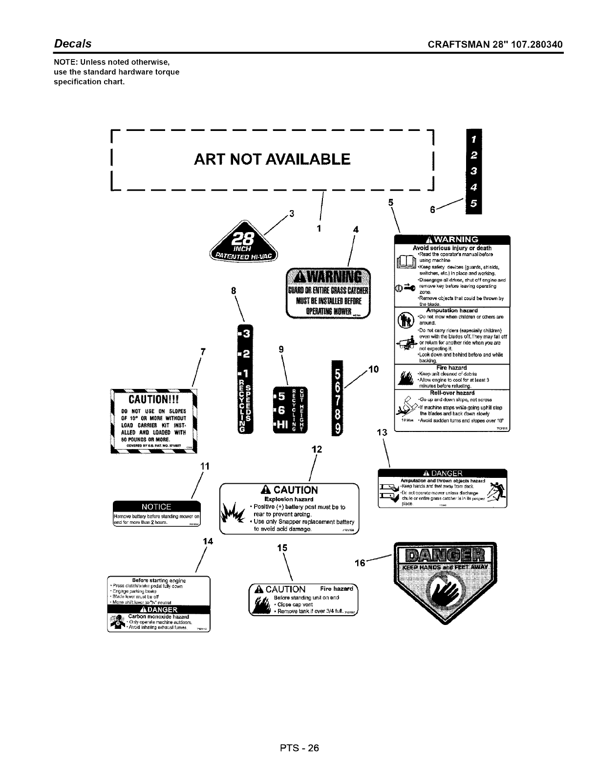
Decals CRAFTSMAN 28" 107.280340
NOTE: Unless noted otherwise,
use the standard hardware torque
specification chart.
I
i
IART NOT AVAILABLE
7
/
11
5
/\
1 4
/
8\
10
12
/
,_ _CAUTION
IF_plosion hazard I
. Positive (+) battery pOsl must be to /
rear to prewnt aml_g. /
• Use oi_ly Snapper re;31acsmer'=t batter J
to avoid acid damage. ,i_,1%)
14
16/
Before sta_lng er_Jirle _i
press clut_IV_rBkE peda[ MI_ down
-Eo0o_op_,_,,__,.,o /(%&CAUTION Fire hazard_
•Move sbiff_lever _ ".* ne_¢,_ I _l_J. " Close cap vent /
_l_m • Remove tank if over 314 full 7,o,,o_
-_'" •Oqly oFeraqe machine outdoors.
I
J
8/
Avoid serious injury or death
_ *Read the operators manual before
using machin_
"Ke_p safety devi3e_, (gLlar&_. $_leld&
switches, etc.} in pl_c_ and wodd_g.
•DLsi_ngage 8_1d_v_, shut _f engine a_d
_'_ _al) remove,k,W bab_ _avlng operating
zer_e.
,Remove ebjec'_ that couid be _rc,_n by
the _4ade.
Amputation hazard
,Do not m_v when _il_r_n ore?hem are
_round,
•Do not can7 r_ers (_pe_a_ly children}
even with _e blades _f.T_ey may fail _ft
or relu_ for another dde when you are
nel e)_3ectin£ it.
•Look down and beh_d bo'fo'_and while
backing.
Fire hazard
•Keep Unit clea ne_ o" debris
•N_ow engine to ccol for Bt teas_ 3
minutes before r_uellr.g.
Roll-over hazar_
"Go up _nd down s_pe, not across
_L_,lf m_chine s_ps w_ls going u pltll stop
the blades and back ddwn slowly
1oMa_ "A_oid sudden lures Brld slopes over !
13 ......
t
Amputation artd thrr_wn objects h_zard
I::]1:_111 .KBBp ha_qdsand f_ef away from d-_ _:
•D_ neloperate mower unless _scharge
t-- _ ......... J
PTS 26

Decals
REF NO
1
3
4
5
6
7
8
9
10
11
12
13
14
15
16
PART NO.
7103999YP
7023996YP
7046720SM
7101111YP
7046218YP
7011910YP
7017176SM
7017328YP
7022325YP
7101109YP
7101108YP
7101110YP
7101112YP
7101107YP
7013010SM
QTY.
1
1
1
1
1
1
1
1
1
1
1
1
1
1
1
DESCRIPTION
DECAL
DECAL
DECAL
DECAL
DECAL
DECAL
DECAL
DECAL
DECAL
DECAL
DECAL
DECAL
DECAL
DECAL
DECAL
Craftsman
28 Inch (Hi-Vac)
Chute/Deflector Warning
Warning, Safety Panel
Height of Cut
Grass Catcher
Recy Ground Speed
Recy Height-Of-Cut
Height-Of-Cut
Remove Battery
Caution, Battery
Danger, Deck
Danger, Safety Panel
Caution, Fuel
Danger, Cut Finger
CRAFTSMAN 28" 107.280340
Footnotes
PTS-27
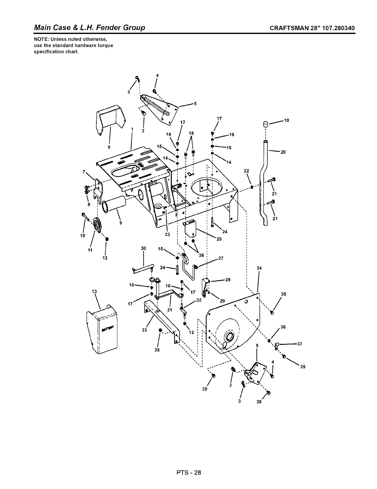
Main Case & L.H. Fender Group CRAFTSMAN 28" 107.280340
NOTE: Unless noted otherwise,
use the standard hardware torque
specification chart.
6
4
3 I e,
17
1 2 16 18
\8I
12
30
13
\
33
26
i
24
25
34
PTS -28

Main Case & L.H. Fender Group CRAFTSMAN 28" 107.280340
REF NO PART NO.
1 7053697YP
2 7028200SM
3 7091503SM
4 7090793YP
5 7034299YP
6 7073268YP
7 7074210YP
8 7091198SM
9 7074650YP
10 7090358YP
11 7031100YP
12 7010969YP
13 7028990YP
14 7011791SM
15 7090188SM
16 7091315SM
17 7091297SM
18 7090595SM
19 7010153YP
20 7030798ZYP
21 7091506YP
22 7090188SM
23 7091272YP
24 7091513YP
25 7047189YP
26 7090585MA
27 7017653YP
28 7073735YP
29 7090981YP
30 7023676YP
31 7041384YP
32 7011018YP
33 7033799YP
34 7037285YP
35 7090361YP
36 7090391SM
37 7012652YP
38 7090206YP
QTY.
1
2
2
4
2
1
1
2
1
1
1
2
1
4
4
7
7
2
2
2
4
2
7
4
1
6
1
1
2
1
1
1
1
1
14
1
1
1
DESCRIPTION
WELDMENT, Main Case (Standard)
SWIVEL, Adjustable
HAIR PIN, 3/32 x 1-1/2"
SCREW, 5/16-18 x 3/4" Hex Washer Self-Tap
WING, Rear
COVER, Solenoid
BRACKET, Belt Adjuster
SCREW, 3/8-16 x 5/8" Hex Washer Self-Tap
BUSHING, Pivot
SCREW, 5/16-24 x 2-1/2" Hex Head Cap, GR 5
TUBE CLAMP
NUT, 5/16-24 Flange Lock (Large)
COVER, Battery
RETAINER, 5/16" Bolt
WASHER, 5/16" Fiat
WASHER, .32 x .58 x .08 Split Lock
NUT, 5/16-24 Hex, GR 5
BOLT, 5/16-18 x 3/4" Hex Flange Lock, GR 5
CAP, Bumper
BUMPER, Rear
SCREW, 5/16-18 x 1-1/2" Hex Washer Self-Tap
WASHER, 11/32" Fiat
FASTENER, 1/4" Ratchet
SCREW, 5/16-24 x 1-3/4" Hex Head Cap, GR 5
BRACKET, Drive Support
NUT, 5/16-18 Hex Flange Lock, GR 5
BELT GUIDE, 25, 26, 28, 41" (5.74" Bolt Pattern, 4.74" Belt Gap)
BRACKET, Switch
SCREW, #10-32 x 1/4" Hex Washer Self-Tap
SHIFT LINK, Long (5/16-24 both ends)
WELDMENT, Shift Arm
SHIFT LINK, Short (5/16-24 thread)
CROSS BRACE
FENDER, Left Hand (1.628" I. D. Hole)
SCREW, 5/16-18 x 5/8" Hex Washer Self-Tap
WASHER, 5/16" Internal Tooth Lock
CLIP, Wire
SCREW, 5/16-18 x 3/4" Hex Head Cap, GR 5
Footnotes
PTS - 29
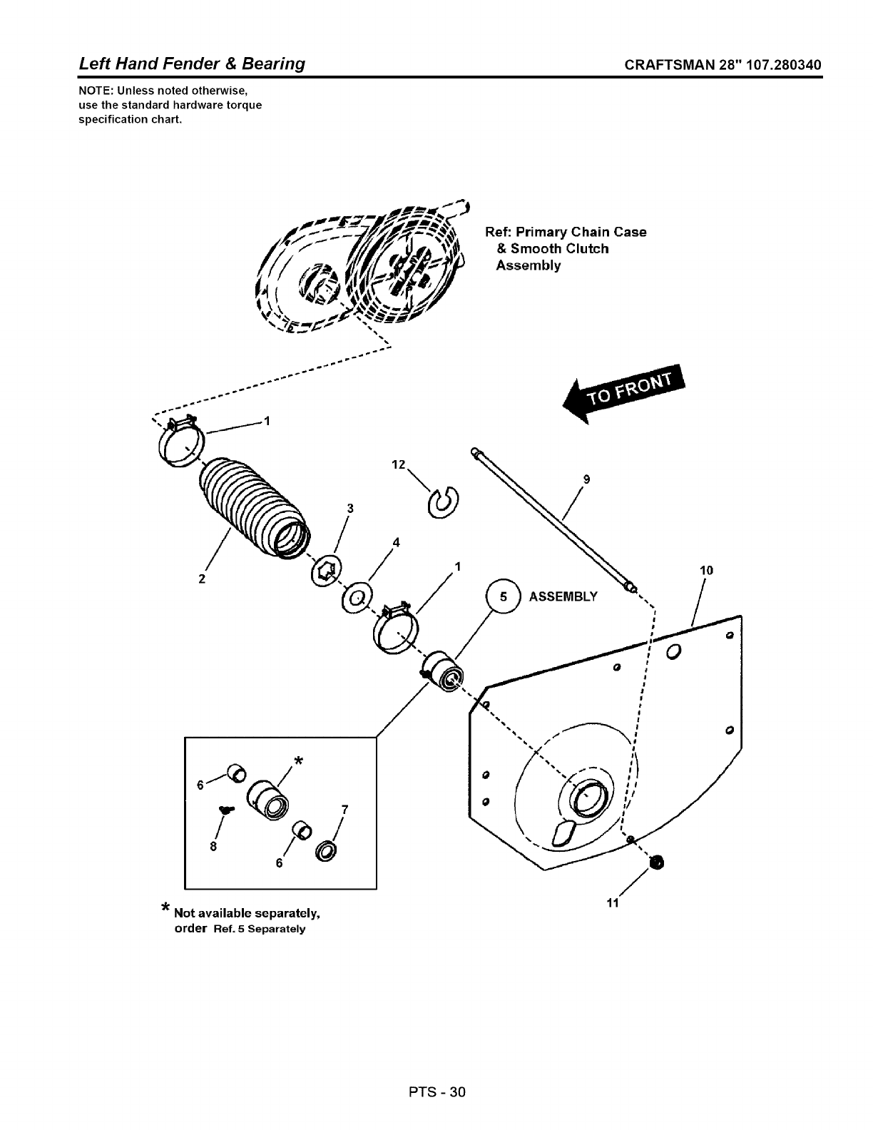
Left Hand Fender & Bearing CRAFTSMAN 28" 107.280340
NOTE: Unless noted otherwise,
use the standard hardware torque
specification chart.
Ref: Primary Chain Case
& Smooth Clutch
Assembly
3
/
0J_ .-./
6
Not available separately,
order Ref. 5 Separately
12
0
11
lO
0
PTS -30
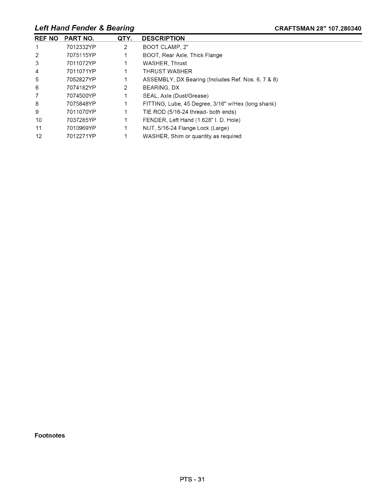
Left Hand Fender CRAFTSMAN 28" 107.280340
REF NO PART NO.
1 7012332YP
2 7075115YP
3 7011072YP
4 7011071YP
5 7052827YP
6 7074182YP
7 7074500YP
8 7075848YP
9 7011070YP
10 7037285YP
11 7010969YP
12 7012271YP
& Bearing
QTY.
2
1
1
1
1
2
1
1
1
1
1
1
DESCRIPTION
BOOT CLAMP, 2"
BOOT, Rear Axle, Thick Flange
WASHER, Thrust
THRUST WASHER
ASSEMBLY, DX Bearing (Includes Ref. Nos. 6, 7 & 8)
BEARING, DX
SEAL, Axle (Dust/Grease)
FITTING, Lube, 45 Degree, 3/16" w/Hex (long shank)
TIE ROD (5/16-24 thread- both ends)
FENDER, Left Hand (1.628" I. D. Hole)
NUT, 5/16-24 Flange Lock (Large)
WASHER, Shim or quantity as required
Footnotes
PTS - 31
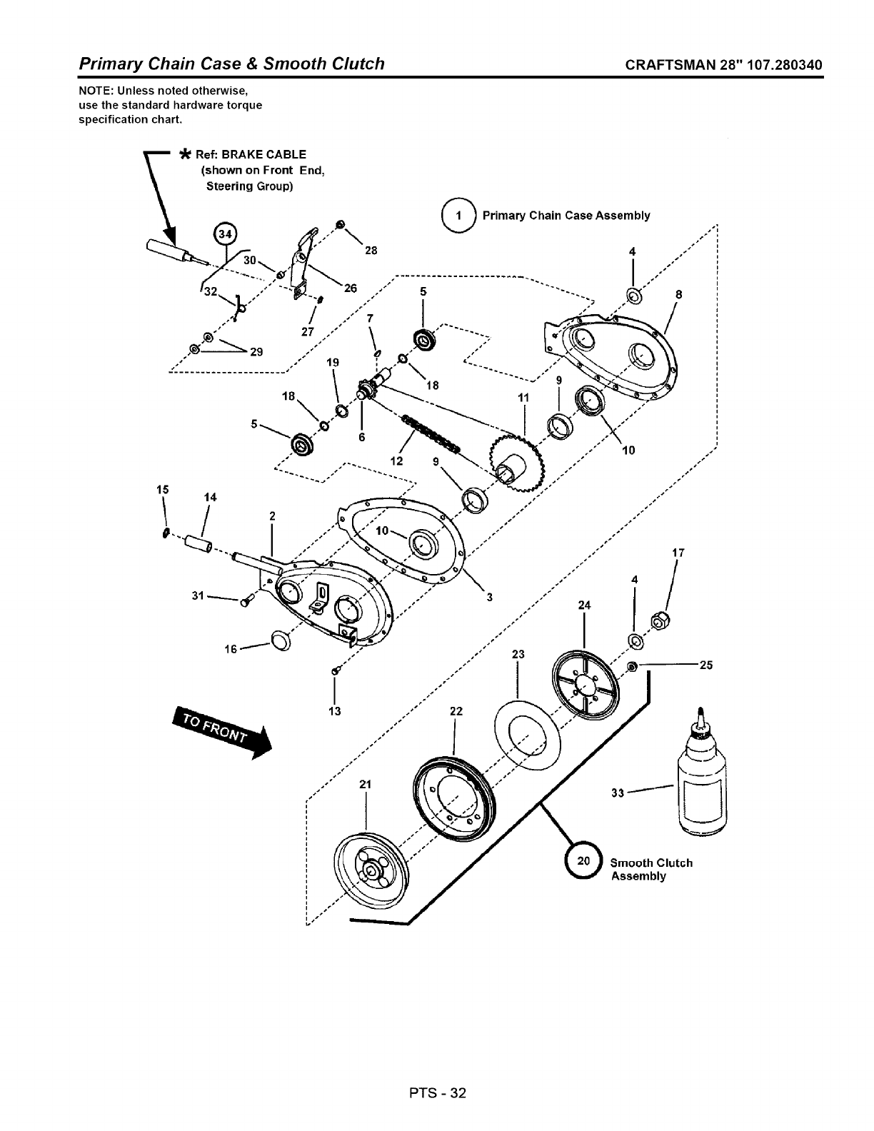
Primary Chain Case & Smooth Clutch CRAFTSMAN 28" 107.280340
NOTE: Unless noted otherwise,
use the standard hardware torque
specification chart.
25
Smooth Clutch
Assembly
PTS -32
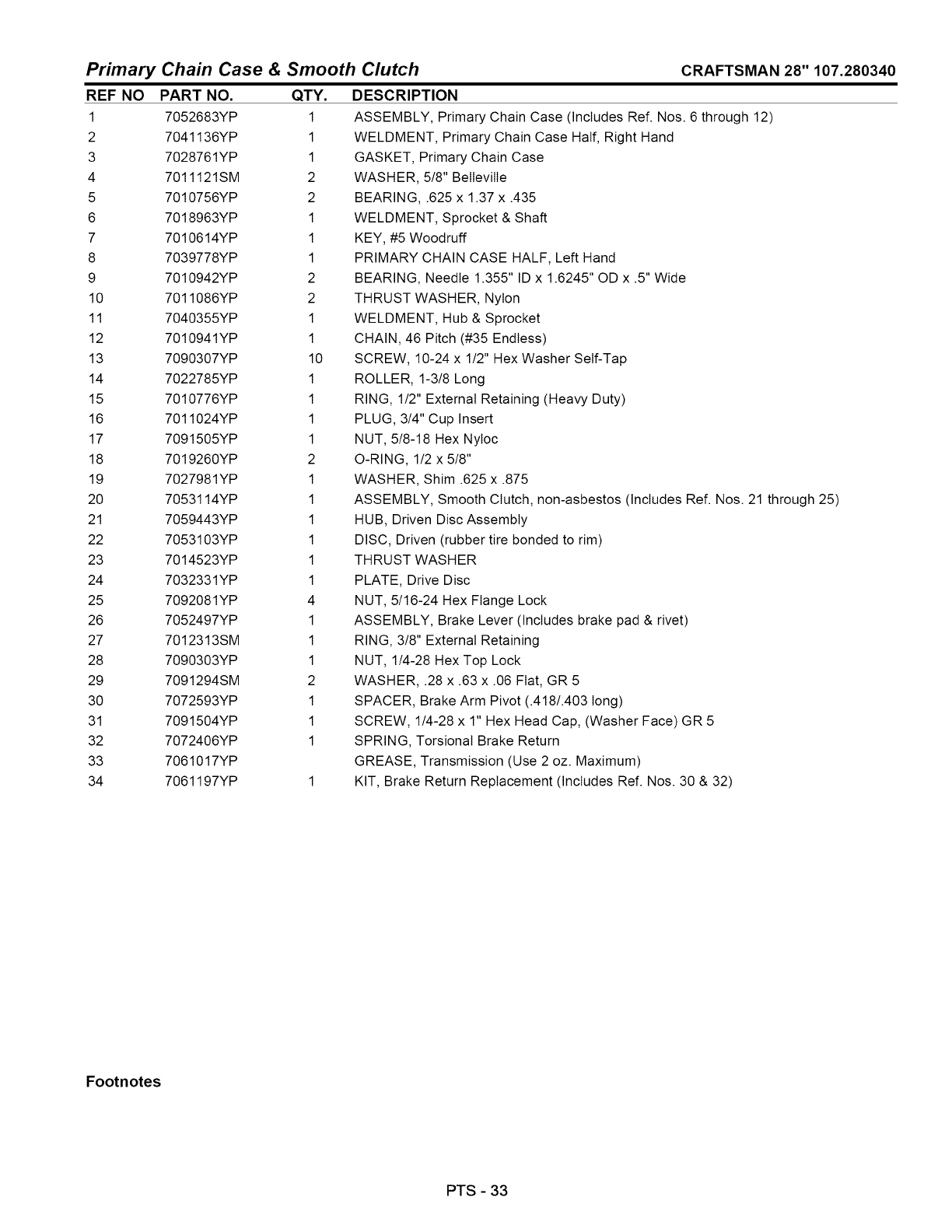
Primary Chain Case & Smooth Clutch
REF NO
1
2
3
4
5
6
7
8
9
10
11
12
13
14
15
16
17
18
19
2O
21
22
23
24
25
26
27
28
29
3O
31
32
33
34
CRAFTSMAN 28" 107.280340
PART NO.
7052683YP
7041136YP
7028761YP
7011121SM
7010756YP
7018963YP
7010614YP
7039778YP
7010942YP
7011086YP
7040355YP
7010941YP
7090307YP
7022785YP
7010776YP
7011024YP
7091505YP
7019260YP
7027981YP
7053114YP
7059443YP
7053103YP
7014523YP
7032331YP
7092081YP
7052497YP
7012313SM
7090303YP
7091294SM
7072593YP
7091504YP
7072406YP
7061017YP
7061197YP
QTY.
1
1
1
2
2
1
1
1
2
2
1
1
10
1
1
1
1
2
1
1
1
1
1
1
4
1
1
1
2
1
1
1
DESCRIPTION
ASSEMBLY, Primary Chain Case (Includes Ref. Nos. 6 through 12)
WELDMENT, Primary Chain Case Half, Right Hand
GASKET, Primary Chain Case
WASHER, 5/8" BelIevilIe
BEARING, .625 x 1.37 x .435
WELDMENT, Sprocket & Shaft
KEY, #5 Woodruff
PRIMARY CHAIN CASE HALF, Left Hand
BEARING, Needle 1.355" ID x 1.6245" OD x .5" Wide
THRUST WASHER, Nylon
WELDMENT, Hub & Sprocket
CHAIN, 46 Pitch (#35 Endless)
SCREW, 10-24 x 1/2" Hex Washer Self-Tap
ROLLER, 1-3/8 Long
RING, 1/2" External Retaining (Heavy Duty)
PLUG, 3/4" Cup Insert
NUT, 5/8-18 Hex NyIoc
O-RING, 1/2 x 5/8"
WASHER, Shim .625 x .875
ASSEMBLY, Smooth Clutch, non-asbestos (Includes Ref. Nos. 21 through 25)
HUB, Driven Disc Assembly
DISC, Driven (rubber tire bonded to rim)
THRUST WASHER
PLATE, Drive Disc
NUT, 5/16-24 Hex Flange Lock
ASSEMBLY, Brake Lever (Includes brake pad & rivet)
RING, 3/8" External Retaining
NUT, 1/4-28 Hex Top Lock
WASHER, .28 x .63 x .06 Fiat, GR 5
SPACER, Brake Arm Pivot (.418/.403 long)
SCREW, 1/4-28 x 1" Hex Head Cap, (Washer Face) GR 5
SPRING, Torsional Brake Return
GREASE, Transmission (Use 2 oz. Maximum)
KIT, Brake Return Replacement (Includes Ref. Nos. 30 & 32)
Footnotes
PTS - 33
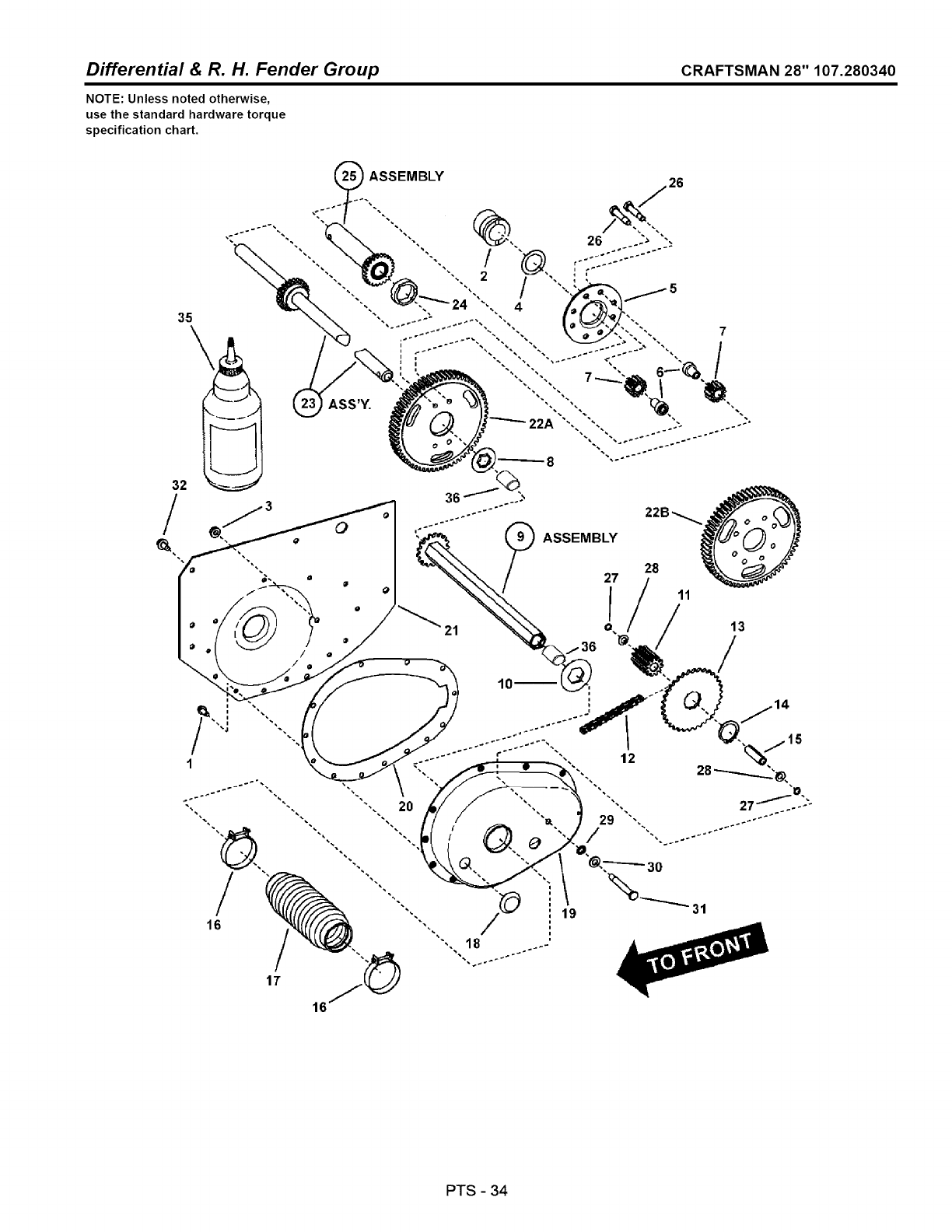
Differential & R. H. Fender Group CRAFTSMAN 28" 107.280340
NOTE: Unless noted otherwise,
use the standard hardware torque
specification chart.
/
35
32 36 :"
'_ ?ASSEMBLY
1
16
17
PTS - 34
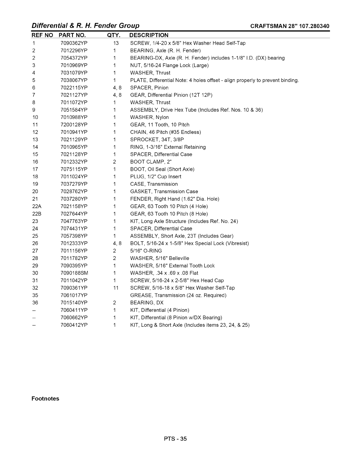
Differential & R. H. Fender Group
REF NO
1
2
2
3
4
5
6
7
8
9
10
11
12
13
14
15
16
17
18
19
2O
21
22A
22B
23
24
25
26
27
28
29
30
31
32
35
36
CRAFTSMAN 28" 107.280340
PART NO.
7090362YP
7012296YP
7054372YP
7010969YP
7031079YP
7038067YP
7022115YP
7021127YP
7011072YP
7051584YP
7010988YP
7200128YP
7010941YP
7021129YP
7010965YP
7021128YP
7012332YP
7075115YP
7011024YP
7037279YP
7028762YP
7037280YP
7021158YP
7027644YP
7047763YP
7074431YP
7057398YP
7012333YP
7011156YP
7011782YP
7090395YP
7090188SM
7011042YP
7090361YP
7061017YP
7015140YP
7060411YP
7060662YP
7060412YP
QTY.
13
1
1
1
1
1
4,8
4,8
1
1
1
1
1
1
1
1
2
1
1
1
1
1
1
1
1
1
1
4,8
2
2
1
1
1
11
2
1
1
1
DESCRIPTION
SCREW, 1/4-20 x 5/8" Hex Washer Head Self-Tap
BEARING, Axle (R. H. Fender)
BEARING-DX, Axle (R. H. Fender) includes 1-1/8" I.D. (DX) bearing
NUT, 5/16-24 Flange Lock (Large)
WASHER, Thrust
PLATE, Differential Note: 4 holes offset - align properly to prevent binding.
SPACER, Pinion
GEAR, Differential Pinion (12T 12P)
WASHER, Thrust
ASSEMBLY, Drive Hex Tube (Includes Ref. Nos. 10 & 36)
WASHER, Nylon
GEAR, 11 Tooth, 10 Pitch
CHAIN, 46 Pitch (#35 Endless)
SPROCKET, 34T, 3/8P
RING, 1-3/16" External Retaining
SPACER, Differential Case
BOOT CLAMP, 2"
BOOT, Oil Seal (Short Axle)
PLUG, 1/2" Cup Insert
CASE, Transmission
GASKET, Transmission Case
FENDER, Right Hand (1.62" Dia. Hole)
GEAR, 63 Tooth 10 Pitch (4 Hole)
GEAR, 63 Tooth 10 Pitch (8 Hole)
KIT, Long Axle Structure (Includes Ref. No. 24)
SPACER, Differential Case
ASSEMBLY, Short Axle, 23T (Includes Gear)
BOLT, 5/16-24 x 1-5/8" Hex Special Lock (Vibresist)
5/16" O-RING
WASHER, 5/16" BelIevilIe
WASHER, 5/16" External Tooth Lock
WASHER, .34 x .69 x .08 Fiat
SCREW, 5/16-24 x 2-5/8" Hex Head Cap
SCREW, 5/16-18 x 5/8" Hex Washer Self-Tap
GREASE, Transmission (24 oz. Required)
BEARING, DX
KIT, Differential (4 Pinion)
KIT, Differential (8 Pinion w/DX Bearing)
KIT, Long & Short Axle (Includes items 23, 24, & 25)
Footnotes
PTS - 35
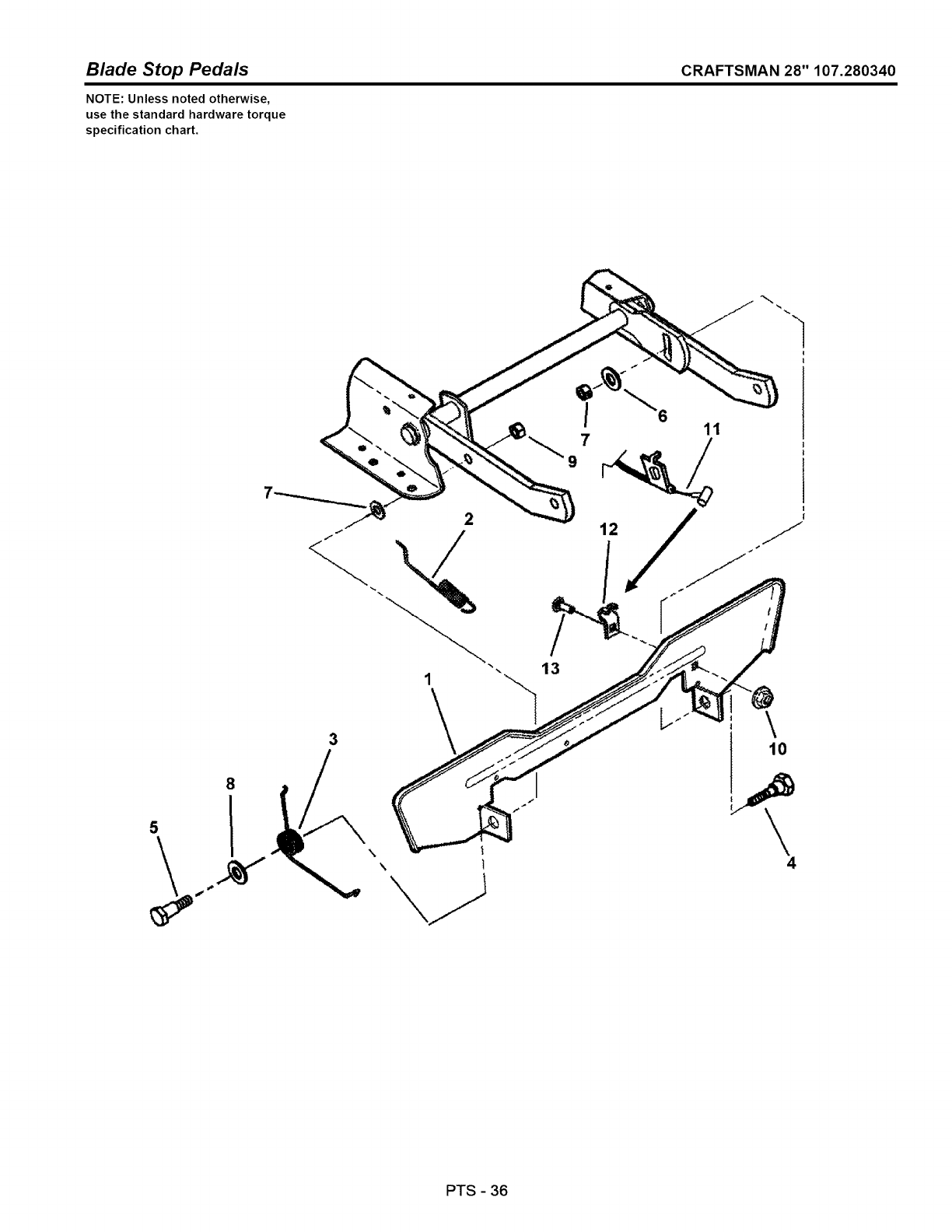
Blade Stop Pedals CRAFTSMAN 28" 107.280340
NOTE: Unless noted otherwise,
use the standard hardware torque
specification chart.
8
5
\t
\ 1
11
13
\
4
PTS -36
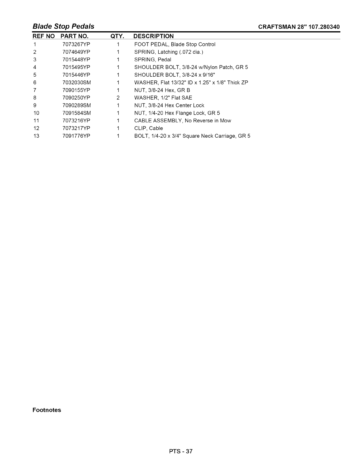
Blade Stop Pedals
REF NO PART NO. QTY.
1 7073267YP 1
2 7074649YP 1
3 7015448YP 1
4 7015495YP 1
5 7015446YP 1
6 7032030SM 1
7 7090155YP 1
8 7090250YP 2
9 7090289SM 1
10 7091584SM 1
11 7073216YP 1
12 7073217YP 1
13 7091776YP 1
DESCRIPTION
FOOT PEDAL, Blade Stop Control
SPRING, Latching (.072 dia.)
SPRING, Pedal
SHOULDER BOLT, 3/8-24 w/Nylon Patch, GR 5
SHOULDER BOLT, 3/8-24 x 9/16"
WASHER, Fiat 13/32" ID x 1.25" x 1/8" Thick ZP
NUT, 3/8-24 Hex, GR B
WASHER, 1/2" Fiat SAE
NUT, 3/8-24 Hex Center Lock
NUT, 1/4-20 Hex Flange Lock, GR 5
CABLE ASSEMBLY, No Reverse in Mow
CLIP, Cable
BOLT, 1/4-20 x 3/4" Square Neck Carriage, GR 5
CRAFTSMAN 28" 107.280340
Footnotes
PTS - 37
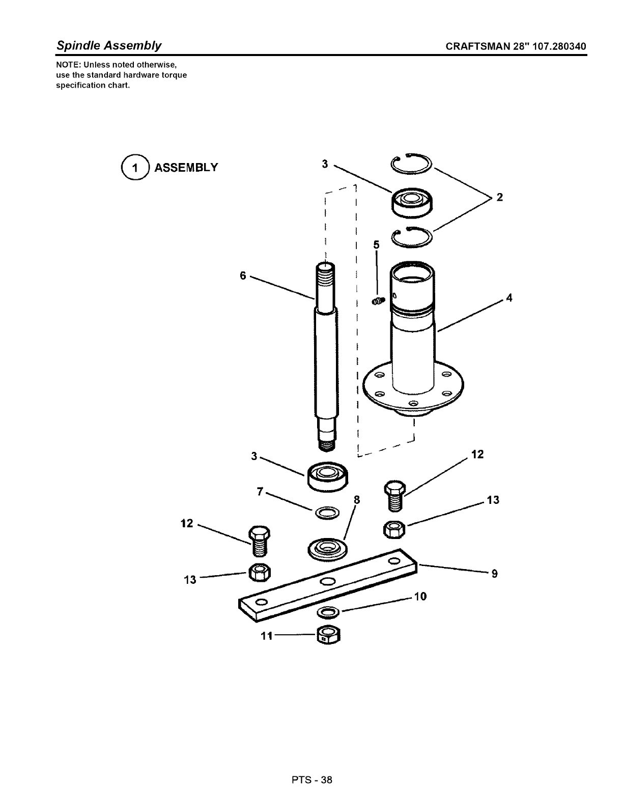
Spindle Assembly CRAFTSMAN 28" 107.280340
NOTE: Unless noted otherwise,
use the standard hardware torque
specification chart.
GASSEMBLY
' 50
t
_tp
A
11
PTS -38

Spindle Assembly
REF NO PART NO. QTY.
1 7058049YP 1
2 7012491SM 2
3 7013313SM 2
4 7050696YP 1
5 7010817SM 1
6 7044785YP 1
7 7010935SM 1
8 7014407SM 1
9 7031184YP 1
10 7044782YP 1
11 7090356YP 1
12 7090491YP 2
13 7091939YP 2
CRAFTSMAN 28" 107.280340
DESCRIPTION
ASSEMBLY, Spindle (Includes Ref. Nos. 2 through 11)
RING, 1.85" Internal Retaining
BEARING, Spindle
ASSEMBLY, Spindle Housing (Includes Ref. No. 5)
LUBE FITTING, 3/16" Press-In
SPINDLE, Rider (10.327" overall length)
WASHER, .77 x 1.13 x .06 Fiat
WASHER, Spindle
HOLDER, Blade
SPACER, Blade Centering
NUT, 5/8-18 Hex Center Lock Jam
SCREW, 1/2-20 x 1-1/4" Hex Head Cap, GR 5
NUT, 1/2-20 Hex, GR 5 or B
Footnotes
PTS -39
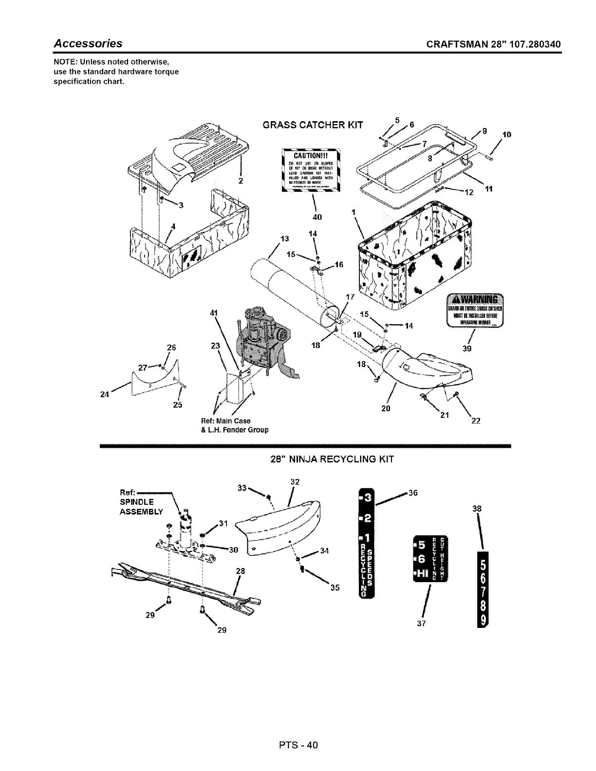
Accessories CRAFTSMAN 28" 107.280340
NOTE: Unless noted otherwise,
use the standard hardware torque
specification chart.
24
GRASS CATCHER KIT
1\
17
26
Z5
41
23\18
Ref: Main Case
& L.H, Fender Group
10
/
39
21 22
28" NINJA RECYCLING KIT
32
Ref: , 33.__., q/
SPINDLE \ \
ASSEMBLY _A 31 _ J _/=I
35
29
/
37
38
PTS -40

A ccessories
REF NO
1
2
3
4
5
6
7
8
9
10
11
12
13
14
15
16
17
18
19
20
21
22
23
24
25
26
27
28
29
30
31
32
33
34
35
36
37
38
39
40
41
PART NO.
7600101YP
7019251YP
7104012YP
7029840YP
7016108YP
7090532YP
7031725YP
7090376YP
7091503SM
7047973YP
7029841YP
7037758YP
7012556YP
7014517YP
7091576SM
7091314YP
7037745YP
7031952YP
7091530SM
7031951YP
7019912YP
7091537YP
7091303YP
7071677YP
7063287YP
7090909YP
7091294SM
7091705SM
7600100YP
7104083YP
7090392YP
7090509YP
7090559YP
7016983YP
7090001YP
7090188SM
7090492YP
7017176SM
7017328YP
7022325YP
7046720SM
7011910YP
7042716YP
QTY.
1
1
1
5
1
1
1
1
2
1
2
1
1
1
3
3
1
1
3
1
1
1
1
1
1
2
2
2
1
1
2
2
2
1
3
3
3
1
1
1
1
1
1
CRAFTSMAN 28" 107.280340
DESCRIPTION
KIT, Single Bag Grass Catcher, 28" (Includes Ref. Nos. 1 through 27)
GRASS BAG, Single, Zippertess
TOP, Grass Container, No Graphics
WASHER, 5/16 Faceted
DUST SKIRT
SCREW, #10-32 x 1-3/8" Hex Head Machine
LATCH, Grass Catcher Top
NUT, #10-32 Hex NyIoc
PIN, 3/32 x 1-1/2" Hair, YZ
FRAME STRUCTURE
PIN, 5/16 x 1-11/16" Clevis
ROD, Bag
CONNECTOR, Bag Rod
GRASS TUBE, 28-33
NUT, 1/4-20 Hex, YZ
WASHER, 1/4" Internal Tooth Lock, YZ
HANDLE, Tube
BASE, Handle
BOLT, 1/4-20 x 3/4" Round Head Short Square Neck Carriage, YZ
LATCH, Tube
ADAPTER, 28" Deck
WING LOCKNUT, 5/16-18, YZ
BOLT, 5/16-18 x 1" Round Head Short Square Neck, GR 5
MUFFLER GUARD, Grass Catcher
SHIELD, Grass Catcher Debris
BOLT, 1/4-20 x 1-1/2" Hex Head
WASHER, 1/4" Fiat
NUT, 1/4-20 Hex top Lock
KIT, Ninja Recycling, 28" Deck (Includes Ref. Nos. 28 through 38)
BLADE, Ninja, 28"
SCREW, 1/2-20 x 1" Hex Head Cap, GR 5
WASHER, 1/2" Internal Tooth Lock
NUT, 1/2-20 Hex Jam, GR 5 or B
COVER, 28" MuIcher
BOLT, 5/16-18 x 3/4" Round Head Short Square Neck Carriage, GR 5
WASHER, 5/16" Fiat
NUT, 5/16-18 Wing
DECAL, Recy Ground Speed
DECAL, Recy Height-Of-Cut
DECAL, Height-Of-Cut
DECAL, Chute/Deflector Warning
DECAL, Grass Catcher
BRACKET, Bumper Reinforcement
Footnotes
PTS - 41
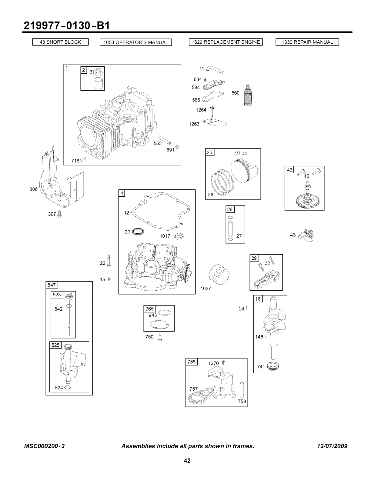
219977-0130-B1
I,_sSnORTBLOCKI I 1055OPERATOR'SMANUALI 1329 REPLACEMENT ENGINE I I 1330 REPAIR MANUAL I
8471
842 _
22_
15
524 O
691
' _,,_ ,...... il, \_
, '_ 1 [ - i
1027
85O
750 _
24 _
758_ 1270
759
161
146
MSCO00200- 2 Assembfies include all parts shown in frames. 12/07/2009
42
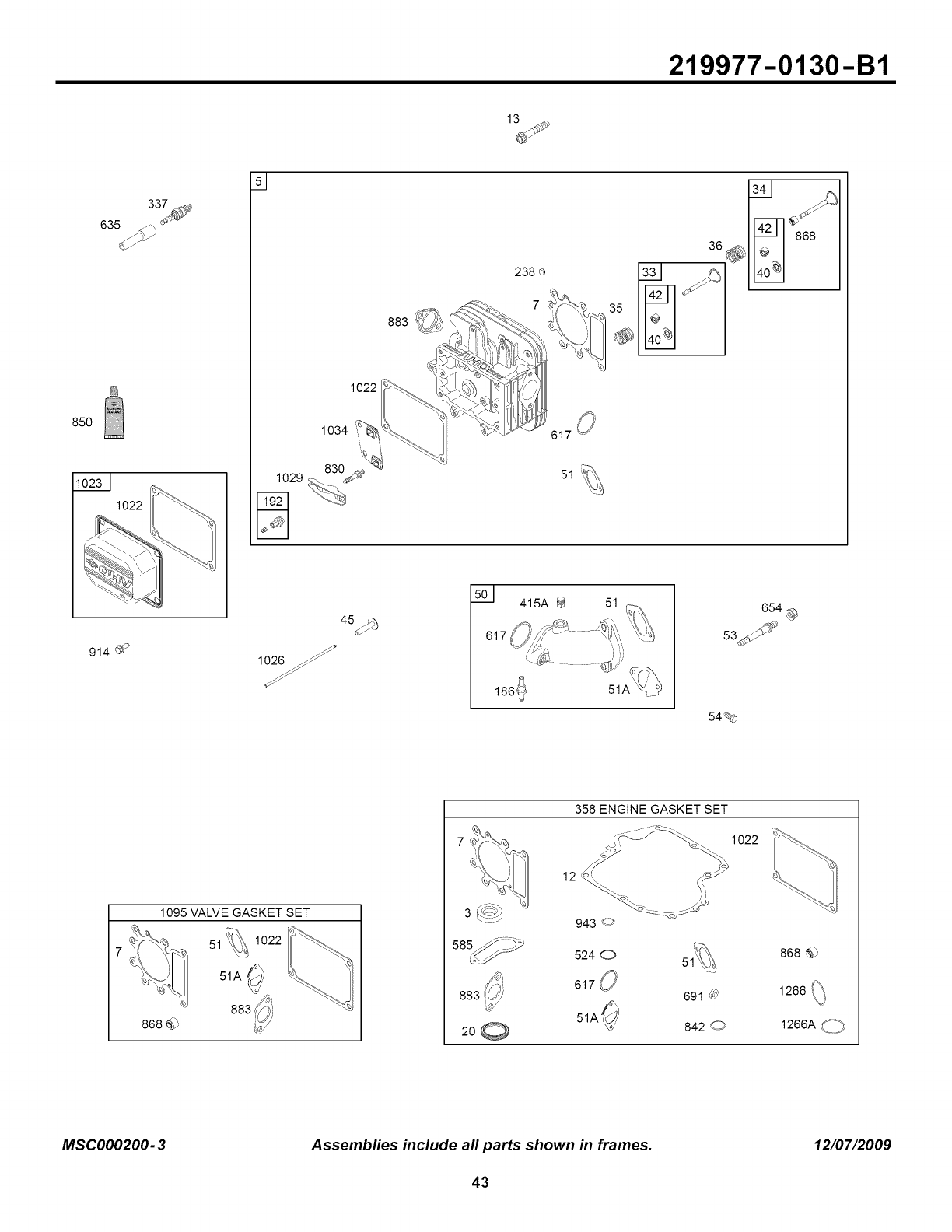
219977-0130-B1
85O
3374_'
635 /_h _;_
1022
d
1O29
D
1022
1034 _
238 ®
914_ 2
45_
1026
501 415A @
186_
54%
654%
1095 VALVE GASKET SET
51 1022
51A
868 _P 200
358 ENGINE GASKET SET
"- 1022
12____
943 ,<_
524 O
617 i_
51A
691 @
8420
868_)
1266(_
1266A(>
MSC000200-3 Assembfies include all parts shown in frames. 12/07/2009
43
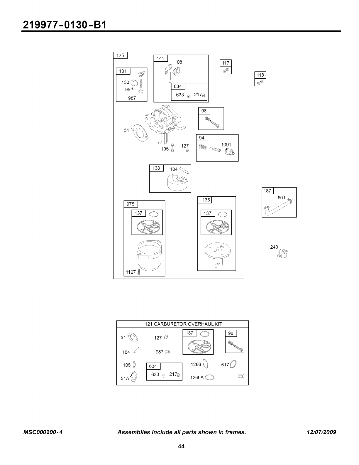
219977-0130-B1
13o©1
95 ¢ (!_>_
987
51
104
108
1127
6o_
[\J
240
51%
104
105
121 CARBURETOR OVERHAUL KIT
127 0 Cp
987 (_
633 ® 217_
617 0
1266A C_
MSC000200-4 Assembfies include all parts shown in frames. 12/07/2009
44
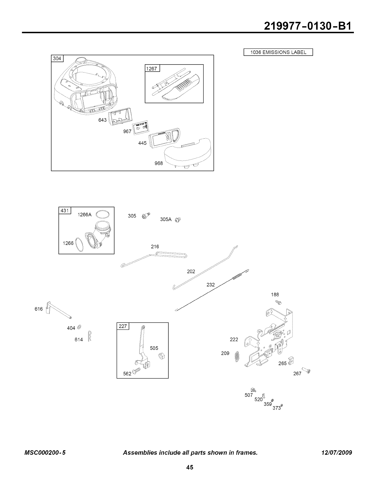
219977-0130-B1
I 1036 EMISSIONS LABEL I
643"
967
445
616
1266AC,>
1266 f_ '_' _-
305 305A _'_
188
404 0
614
2271
!_ 505
562 J_
222
209
507 520_' #
359 373_
MSCO00200- 5 Assembfies include all parts shown in frames. 12/07/2009
45
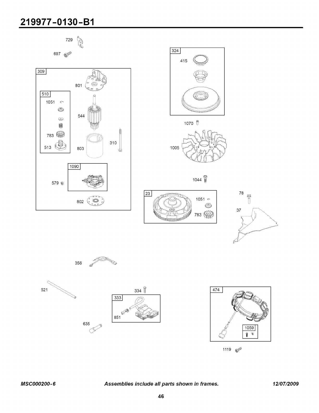
219977-0130-B1
1051
729
697
CoD
@
783 _
513
579 %
801
544
8O3
\ •
310
802 I
415
1070
1044
78
37 ," _
356 ¢/" >_
521 _._\
635
334 _I
MSCO00200- 6Assembfies include all parts shown in frames. 12/07/2009
46
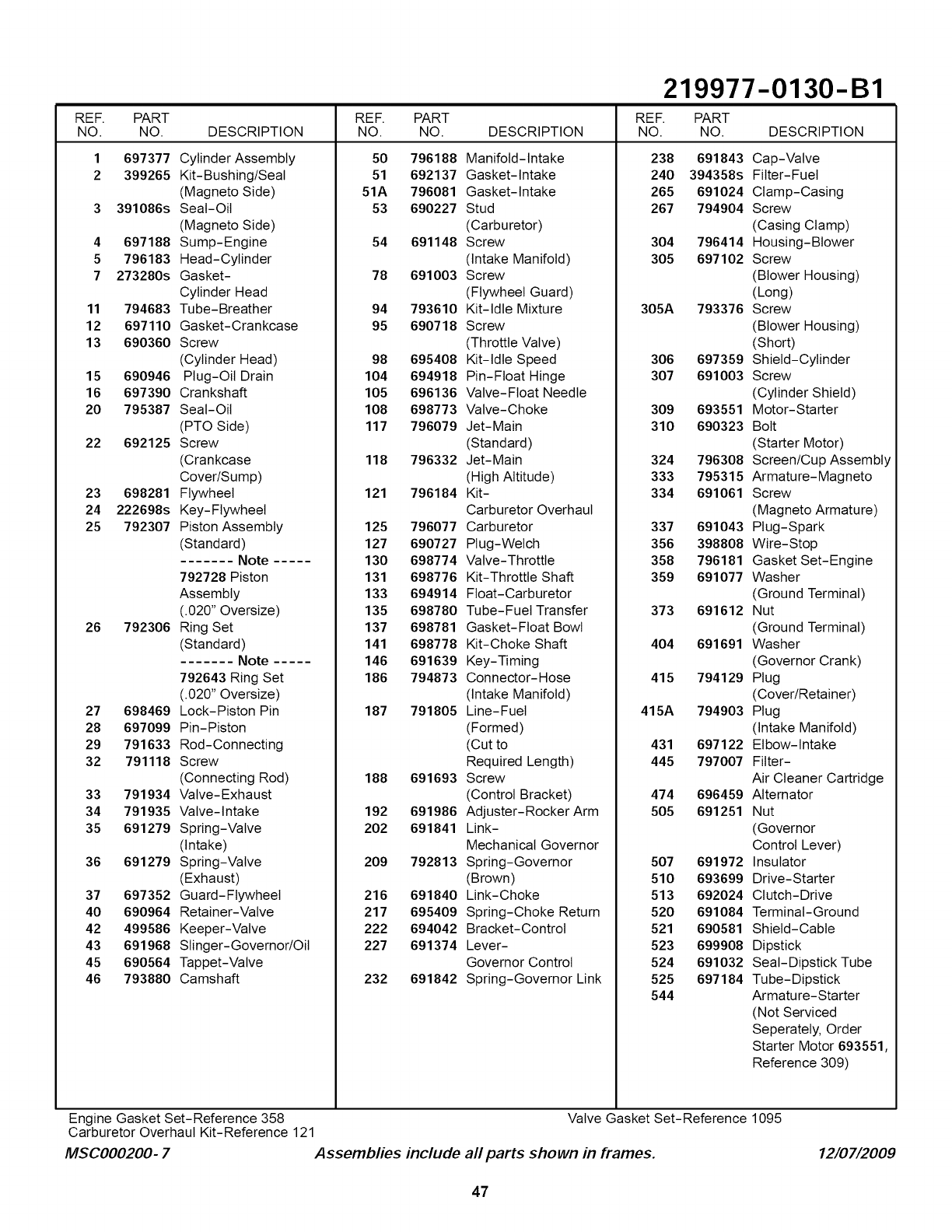
219977-0130-B1
REF. PART REF. PART REF. PART
NO. NO. DESCRIPTION NO. NO. DESCRIPTION NO. NO. DESCRIPTION
1697377 Cylinder Assembly
399265 Kit-Bushing/Seal
(Magneto Side)
3 391086s Seal-Oil
(Magneto Side)
4 697188 Sump-Engine
5 796183 Head-Cylinder
7 273280s Gasket-
Cylinder Head
11 794683 Tube-Breather
12 697110 Gasket-Crankcase
13 690360 Screw
(Cylinder Head)
15 690946 Plug-Oil Drain
16 697390 Crankshaft
20 795387 Seal-Oil
(PTO Side)
22 692125 Screw
(Crankcase
Cover/Sump)
23 698281 Flywheel
24 222698s Key-Flywheel
25 792307 Piston Assembly
(Standard)
....... Note .....
792728 Piston
Assembly
(.020" Oversize)
26 792306 Ring Set
(Standard)
....... Note .....
792643 Ring Set
(.020" Oversize)
27 698469 Lock-Piston Pin
28 697099 Pin-Piston
29 791633 Rod-Connecting
32 791118 Screw
(Connecting Rod)
33 791934 Valve-Exhaust
34 791935 Valve-Intake
35 691279 Spring-Valve
(Intake)
36 691279 Spring-Valve
(Exhaust)
37 697352 Guard-Flywheel
40 690964 Retainer-Valve
42 499586 Keeper-Valve
43 691968 Slinger-Governor/Oil
45 690564 Tappet-Valve
46 793880 Camshaft
50 796188 Manifold-Intake
51 692137 Gasket-Intake 238 691843 Cap-Valve
240 394358s Fitter-Fuel
51A 796081 Gasket-Intake
53 690227 Stud
(Carburetor)
54 691148 Screw
(Intake Manifold)
78 691003 Screw
(Flywheel Guard)
94 793610 Kit-Idle Mixture
95 690718 Screw
(Throttle Valve)
98 695408 Kit-Idle Speed
104 694918 Pin-Float Hinge
105 696136 Valve-Float Needle
108 698773 Valve-Choke
117 796079 Jet-Main
(Standard)
118 796332 Jet-Main
(High Altitude)
121 796184 Kit-
Carburetor Overhaul
125 796077 Carburetor
127 690727 Plug-Welch
130 698774 Valve-Throttle
131 698776 Kit-Throttle Shaft
133 694914 Float-Carburetor
135 698780 Tube-Fuel Transfer
137 698781 Gasket-Float Bowl
141 698778 Kit-Choke Shaft
146 691639 Key-Timing
186 794873 Connector-Hose
(Intake Manifold)
187 791805 Line-Fuel
(Formed)
(Cut to
Required Length)
188 691693 Screw
(Control Bracket)
192 691986 Adjuster-Rocker Arm
202 691841 Link-
Mechanical Governor
209 792813 Spring-Governor
(Brown)
216 691840 Link-Choke
217 695409 Spring-Choke Return
222 694042 Bracket-Control
227 691374 Lever-
Governor Control
232 691842 Spring-Governor Link
265 691024 Clamp-Casing
267 794904 Screw
(Casing Clamp)
304 796414 Housing-Blower
305 697102 Screw
(Blower Housing)
(Long)
305A 793376 Screw
(Blower Housing)
(Short)
306 697359 Shield-Cylinder
307 691003 Screw
(Cylinder Shield)
309 693551 Motor-Starter
310 690323 Bolt
(Starter Motor)
324 796308 Screen/Cup Assembly
333 795315 Armature-Magneto
334 691061 Screw
(Magneto Armature)
337 691043 Plug-Spark
356 398808 Wire-Stop
358 796181 Gasket Set-Engine
359 691077 Washer
(Ground Terminal)
373 691612 Nut
(Ground Terminal)
404 691691 Washer
(Governor Crank)
415 794129 Plug
(Cover/Retainer)
415A 794903 Plug
(Intake Manifold)
431 697122 Elbow-Intake
445 797007 Filter-
Air Cleaner Cartridge
474 696459 Alternator
505 691251 Nut
(Governor
Control Lever)
507 691972 Insulator
510 693699 Drive-Starter
513 692024 Clutch-Drive
520 691084 Terminal-Ground
521 690581 Shield-Cable
523 699908 Dipstick
524 691032 Seal-Dipstick Tube
525 697184 Tube-Dipstick
544 Armature-Starter
(Not Serviced
Seperately, Order
Starter Motor 693551,
Reference 309)
Engine Gasket Set-Reference 358
Carburetor Overhaul Kit-Reference 121 Valve Gasket Set-Reference 1095
M$C000200- 7 Assemblies include all parts shown in frames. 12/07/2009
47
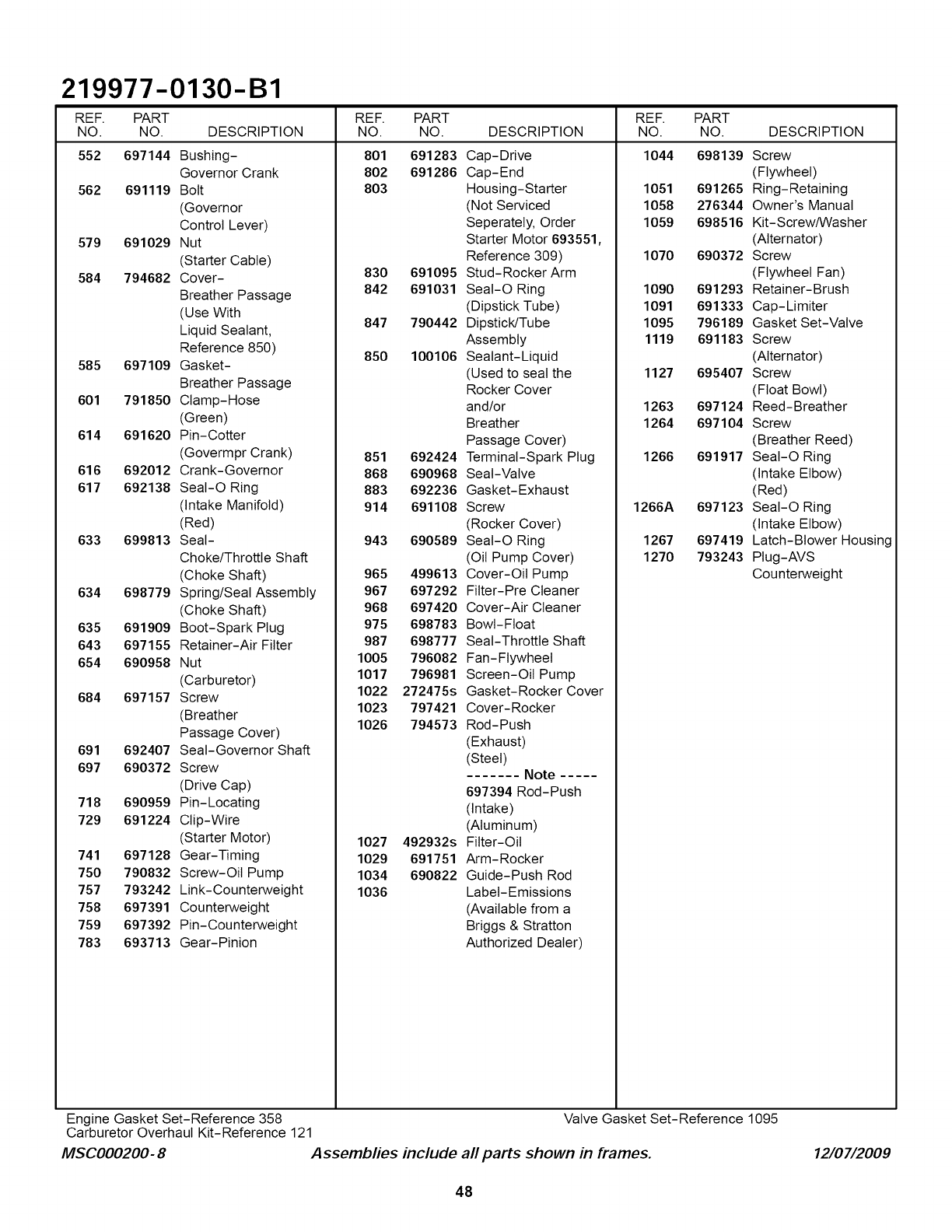
219977-0130-B1
REF. PART PART REF. PART
NO. NO. DESCRIPTION NO. DESCRIPTION NO. NO. DESCRIPTION
552 697144 1044 698139
Bushing-
Governor Crank
562 691119 Bolt
(Governor
Control Lever)
579 691029 Nut
(Starter Cable)
584 794682 Cover-
Breather Passage
(Use With
Liquid Sealant,
Reference 850)
585 697109 Gasket-
Breather Passage
601 791850 Clamp-Hose
(Green)
614 691620 Pin-Cotter
(Govermpr Crank)
616 692012 Crank-Governor
617 692138 SeaI-O Ring
(Intake Manifold)
(Red)
633 699813 Seal-
Choke/Throttle Shaft
(Choke Shaft)
634 698779 Spring/Seal Assembly
(Choke Shaft)
635 691909 Boot-Spark Plug
643 697155 Retainer-Air Filter
654 690958 Nut
(Carburetor)
684 697157 Screw
(Breather
Passage Cover)
691 692407 Seal-Governor Shaft
697 690372 Screw
(Drive Cap)
718 690959 Pin-Locating
729 691224 Clip-Wire
(Starter Motor)
741 697128 Gear-Timing
750 790832 Screw-Oil Pump
757 793242 Link-Counterweight
758 697391 Counterweight
759 697392 Pin-Counterweight
783 693713 Gear-Pinion
REF.
NO.
801
8O2
8O3
691283
691286
830 691095
842 691031
847 790442
850 100106
851 692424
868 690968
883 692236
914 691108
943 690589
965 499613
967 697292
968 697420
975 698783
987 698777
1005 796082
1017 796981
1022 272475s
1023 797421
1026 794573
1027 492932s
1029 691751
1034 690822
1036
Cap-Drive
Cap-End
Housing-Starter
(Not Serviced
Seperately, Order
Starter Motor 693551,
Reference 309)
Stud- Rocker Arm
Seal-O Ring
(Dipstick Tube)
Dipstick/Tube
Assembly
Sealant-Liquid
(Used to seal the
Rocker Cover
and/or
Breather
Passage Cover)
Terminal-Spark Plug
Seal-Valve
Gasket-Exhaust
Screw
(Rocker Cover)
SeaI-O Ring
(Oil Pump Cover)
Cover-Oil Pump
Fitter-Pre Cleaner
Cover-Air Cleaner
Bowl-Float
Seal-Throttle Shaft
Fan- Flywheel
Screen-Oil Pump
Gasket-Rocker Cover
Cover- Rocker
Rod-Push
(Exhaust)
(Steel)
....... Note .....
697394 Rod-Push
(Intake)
(Aluminum)
Fitter-Oil
Arm- Rocker
Guide-Push Rod
Label-Emissions
(Available from a
Briggs & Stratton
Authorized Dealer)
1051 691265
1058 276344
1059 698516
1070 690372
1090 691293
1091 691333
1095 796189
1119 691183
1127 695407
1263 697124
1264 697104
1266 691917
1266A 697123
1267 697419
1270 793243
Screw
(Flywheel)
Ring-Retaining
Owner's Manual
Kit-Screw/Washer
(Alternator)
Screw
(Flywheel Fan)
Retainer- Brush
Cap-Limiter
Gasket Set-Valve
Screw
(Alternator)
Screw
(Float Bowl)
Reed- Breather
Screw
(Breather Reed)
SeaI-O Ring
(Intake Elbow)
(Red)
SeaI-O Ring
(Intake Elbow)
Latch-Blower Housing
PIug-AVS
Counterweight
Engine Gasket Set-Reference 358
Carburetor Overhaul Kit-Reference 121 Valve Gasket Set-Reference 1095
M$C000200- 8 Assemblies include all parts shown in frames. 12/07/2009
48
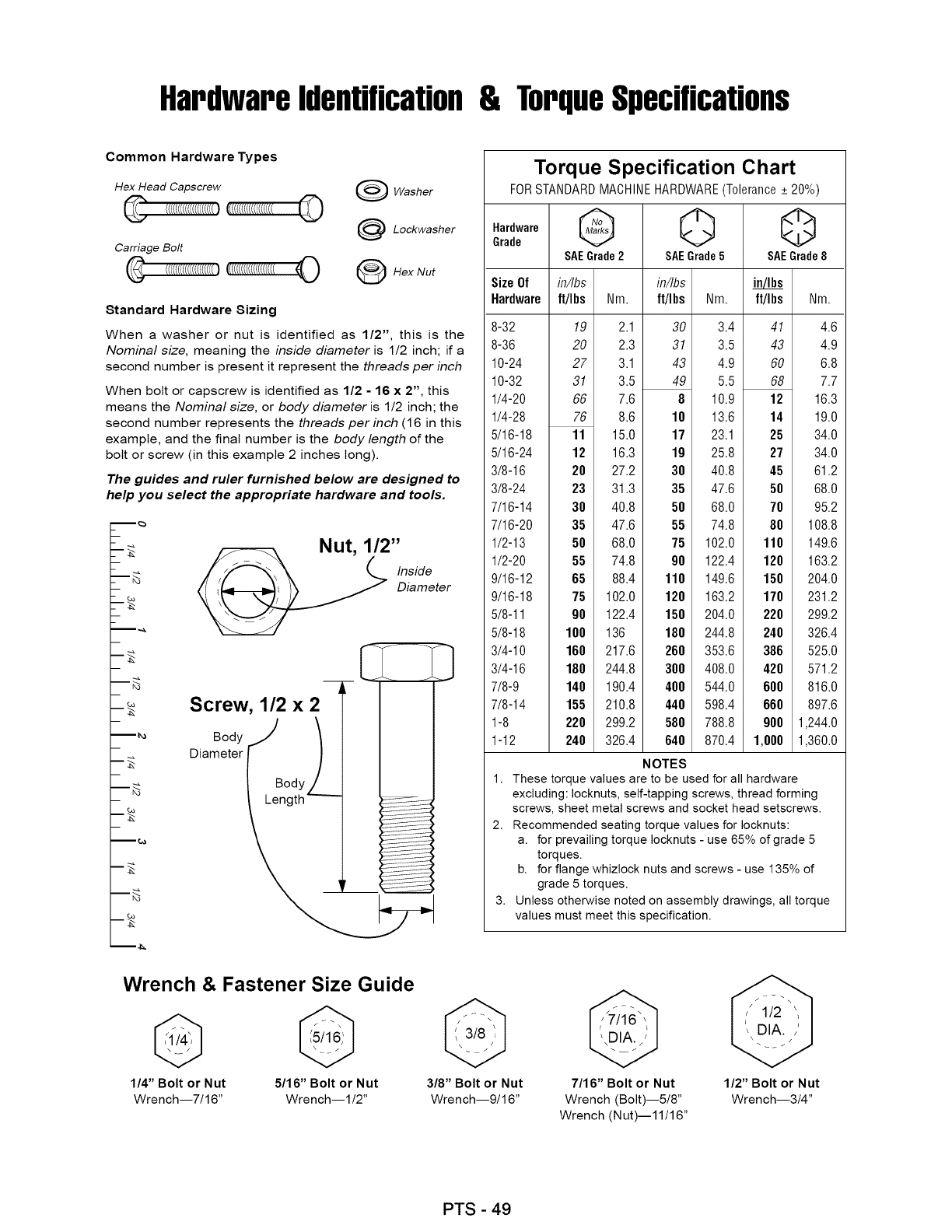
Hardwareidentification& TorqueSpecifications
Common Hardware Types
Hex Head Capscrew
Carriage Bolt
[(((((((((((((((((((O
Washer
Lockwasher
OHex Nut
Standard Hardware Sizing
When a washer or nut is identified as 1/2", this is the
Nominal size, meaning the inside diameter is 1/2 inch; if a
second number is present it represent the threads per inch
When bolt or capscrew is identified as 1/2 - 16 x 2", this
means the Nominal size, or body diameter is 1/2 inch; the
second number represents the threads per inch (16 in this
example, and the final number is the body length of the
bolt or screw (in this example 2 inches long).
The guides and ruler furnished below are designed to
help you select the appropriate hardware and tools.
m_
m_
m_
m_
m_
m_
m_
m_
Nut, 1/2"
Inside
Diameter
Screw, 1/2 x2_- I
o0yj I
Oa eter("/
__@
Torque Specification Chart
FOR STANDARD MACHINE HARDWARE (Tolerance + 20%)
_raarddeware G 0 Q
SAEGrade2 SAEGrade5 SAEGrade8
Size Of in/Ibs
Hardware ft/I bs ft/I bs Nm.
8-32
8-36
10-24
10-32
1/4-20
1/4-28
5/16-18
5/16-24
3/8-16
3/8-24
7/16-14
7/16-20
1/2-13
1/2-20
9/16-12
9/16-18
5/8-11
5/8-18
3/4-10
3/4-16
7/8-9
7/8-14
1-8
1-12
19
20
27
31
66
76
11
12
20
23
30
35
50
55
65
75
90
100
160
180
140
155
220
240
in/Ibs
Nm. ft/Ibs Nm.
2.1 30 3.4
2.3 31 3.5
3.1 43 4.9
3.5 49 5.5
7.6 8 10.9
8.6 18 13.6
15.0 17 23.1
16.3 19 25.8
27.2 38 40.8
31.3 35 47.6
40.8 50 68.0
47.6 55 74.8
68.0 75 102.0
74.8 98 122.4
88.4 118 149.6
102.0 120 163.2
122.4 150 204.0
136 188 244.8
217.6 260 353.6
244.8 300 408.0
190.4 400 544.0
210.8 440 598.4
299.2 588 788.8
326.4 648 870.4
41 4.6
43 4.9
60 6.8
68 7.7
12 16.3
14 19.0
25 34.0
27 34.0
45 61.2
58 68.0
70 95.2
88 108.8
118 149.6
128 163.2
158 204.0
178 231.2
228 299.2
248 326.4
386 525.0
428 571.2
688 816.0
668 897.6
988 1,244.0
1,888 1,360.0
NOTES
1. These torque values are to be used for all hardware
excluding: Iocknuts, self-tapping screws, thread forming
screws, sheet metal screws and socket head setscrews.
2. Recommended seating torque values for Iocknuts:
a. for prevailing torque Iocknuts - use 65% of grade 5
torques.
b. for flange whizlock nuts and screws - use 135% of
grade 5 torques.
3. Unless otherwise noted on assembly drawings, all torque
values must meet this specification.
Wrench & Fastener Size Guide
1/4" Bolt or Nut
Wrench--7/16"
5/16" Bolt or Nut
Wrench--I/2"
3/8" Bolt or Nut
Wrench--9/16"
7/16" Bolt or Nut
Wrench (Bolt)--5/8"
Wrench (Nut)--11/16"
1/2" Bolt or Nut
Wrench--3/4"
PTS - 49

PTS - 50

anual operaclor
®
Tractor cortac_speci con motor trasero con arranque
el_ctrico
Modelo N°
107.280340 (Motor Briggs & Stratton de 12,5 HP con plataforma del
cortac_sped de 71 cm [28 pulg.])
Para obtener respuestas a sus preguntas
sobre este producto, Ilame al:
1-800-659=5917
Linea de ayuda de Sears Craftsman
Lunes a sabado de 5 a.m. a 5 p.m.
Sears, Roebuck and Co., Hoffman Estates, IL 60179 EE.UU.
Visite nuestro sitio Web de Craftsman: www.sears.com/craftsman
7103268
Modificaci6n A

Gracias por comprar este producto fabricado con la calidad Craftsman. Nos complace que
haya depositado su confianza en nuestra marca. Cuando se opera y se mantiene segOn las
instrucciones de este manual, su producto Craftsman le puede brindar muchos ahos de servicio
confiable.
Este manual contiene informaci6n de segufidad para que tome conciencia de los peligros y
riesgos asociados a esta mAquina y c6mo evitarlos. Esta mAquina se disefi6 y pens6 solamente
para obtener un corte de acabado de cesped establecido y no fue prevista para otros prop6sitos.
Es importante que lea y comprenda a cabalidad estas instrucciones antes de que intente arrancar
u operar este equipo. Guarde estas instrucciones para consultas futuras.
AFTSMAN®
fii iliiifiiiil
Sear II_!_liiiitl XXXI_I_
-%/
Nombre/n_mero de doscripci6n dol modolo
Namoro de inventario
Fecha de compra
NtJmoro do serio de la unidad
Fabficante dol motor
Tipo/especiticaciones dol motor
Modolo dol motor
Cbdigo/namero de serie dol motor
Cuando se comunique con el centro de
mantenimiento para pedir piezas de repuesto,
mantenimiento o informaci6n, el usuario DEBE
tener estos nQmeros a su disposici6n.
Registre su nombre/numero de modelo, los numeros de
identificaci6n del fabficante y los numeros de sefie del
motor en el espacio proporcionado para tener un acceso
f&cil.
La etiqueta de identificaci6n est& situada en el lado de
abajo del asiento. Incline el asiento hacia delante para
acceder a la etiqueta de identificaci6n.
Para obtener respuestas a sus preguntas sobre este
producto, Ilame a la linea de ayuda de Sears Craftsman en
el 1-800-659-5971, de lunes a sabado de 5 a.m. a 5 p.m.
2
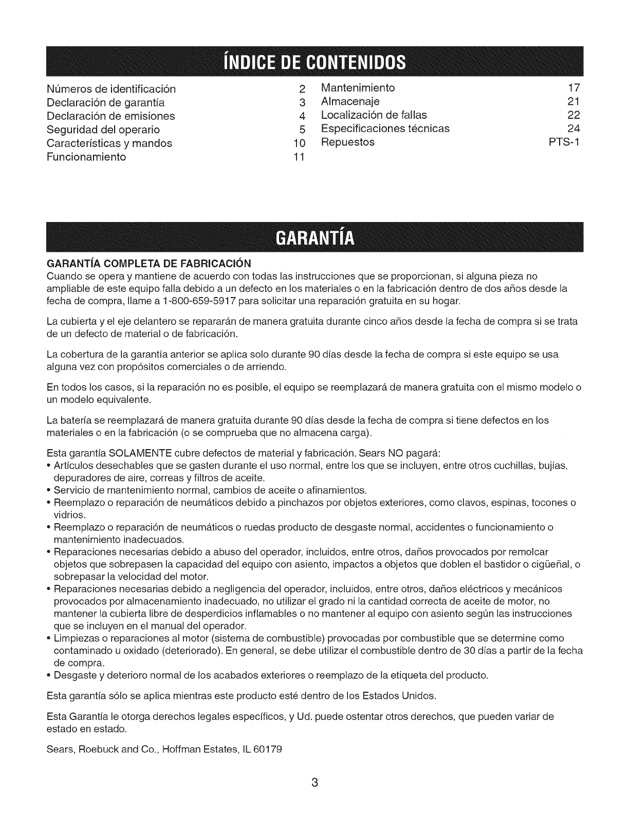
Numeros de identificaci6n
Declaraci6n de garantia
Declaraci6n de emisiones
Seguridad del operario
Caracteristicas y mandos
Funcionamiento
2 Mantenimiento 17
3 Almacenaje 21
4 Localizaci6n de fallas 22
5 Especificaciones tecnicas 24
10 Repuestos PTS- 1
11
GARANT|A COMPLETA DE FABRICACION
Cuando se opera y mantiene de acuerdo con todas las instrucciones que se proporcionan, si alguna pieza no
ampliable de este equipo falla debido a un defecto en los materiales o en la fabricacidn dentro de dos afios desde la
fecha de compra, Ilame a 1-800-659-5917 para solicitar una reparacidn gratuita en su hogar.
La cubierta y el eje delantero se repararan de manera gratuita durante cinco afios desde la fecha de compra si se trata
de un defecto de material o de fabricacidn.
La cobertura de la garantfa anterior se aplica solo durante 90 dfas desde la fecha de compra si este equipo se usa
alguna vez con prop6sitos comerciales o de arriendo.
En todos los casos, si la reparacidn no es posible, el equipo se reemplazara de manera gratuita con el mismo modelo o
un modelo equivalente.
La baterfa se reemplazara de manera gratuita durante 90 dfas desde la fecha de compra si tiene defectos en los
materiales o en la fabricaci6n (o se comprueba que no almacena carga).
Esta garantfa SOLAMENTE cubre defectos de material y fabricacidn. Sears NO pagara:
• Artfculos desechables que se gasten durante el uso normal, entre los que se incluyen, entre otros cuchillas, bujfas,
depuradores de aire, correas y filtros de aceite.
Servicio de mantenimiento normal, cambios de aceite o afinamientos.
Reemplazo o reparaci6n de neumaticos debido a pinchazos por objetos exteriores, como clavos, espinas, tocones o
vidrios.
Reemplazo o reparacidn de neumaticos o ruedas producto de desgaste normal, accidentes o funcionamiento o
mantenimiento inadecuados.
Reparaciones necesarias debido a abuso del operador, incluidos, entre otros, dafios provocados por remolcar
objetos que sobrepasen la capacidad del equipo con asiento, impactos a objetos que doblen el bastidor o cigQefial, o
sobrepasar la velocidad del motor.
Reparaciones necesarias debido a negligencia del operador, incluidos, entre otros, dafios electricos y mecanicos
provocados por almacenamiento inadecuado, no utilizar el grado ni la cantidad correcta de aceite de motor, no
mantener la cubierta libre de desperdicios inflamables o no mantener al equipo con asiento segQn las instrucciones
que se incluyen en el manual del operador.
Limpiezas o reparaciones al motor (sistema de combustible) provocadas por combustible que se determine como
contaminado u oxidado (deteriorado). En general, se debe utilizar el combustible dentro de 30 dfas a partir de la fecha
de compra.
Desgaste y deterioro normal de los acabados exteriores o reemplazo de la etiqueta del producto.
Esta garantfa s61ose aplica mientras este producto este dentro de los Estados Unidos.
Esta Garantfa le otorga derechos legales especfficos, y Ud. puede ostentar otros derechos, que pueden variar de
estado en estado.
Sears, Roebuck and Co., Hoffman Estates, IL 60179
3
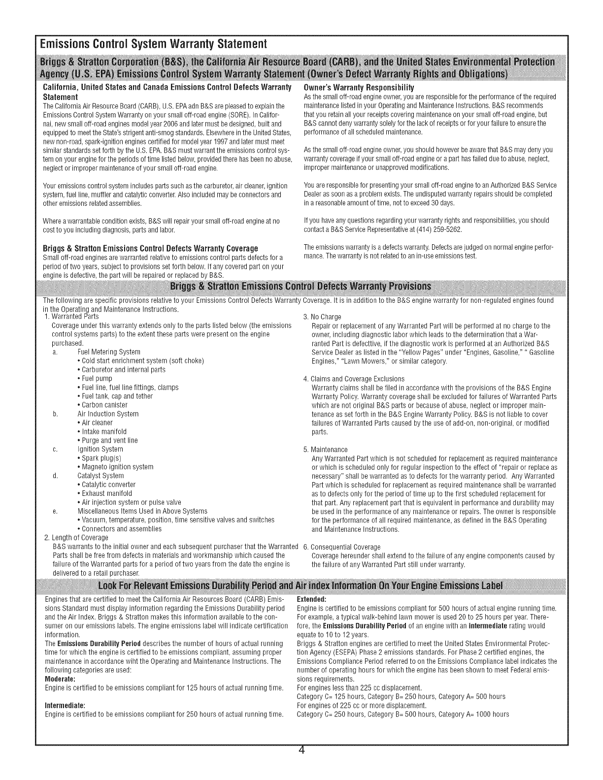
EmissionsControl System WarrantyStatement
California, United States and Canada Emissions Control Defects Warranty
Statement
TheCaliforniaAir ResourceBoard(CARB),U.S.EPAadnB&Sare pleasedto explainthe
EmissionsControlSystemWarrantyonyour smalloff-roadengine(SORE).In Califor-
nai,newsmalloff-roadenginesmodelyear2006andlatermust bedesigned,built and
equippedto meetthe State'sstrigentanti-smogstandards.Elsewherein theUnitedStates,
newnon-road,spark-ignitionenginescertifiedfor modelyear1997and latermustmeet
similarstandardssetforth bythe U.S.EPA.B&Smustwarrantthe emissionscontrol sys-
tem on yourenginefor the periodsof timelistedbelow,providedtherehasbeenno abuse,
neglector impropermaintenanceof your smalleli-roadengine.
Your emissions control system includes parts such as the carburetor, air cleaner, ignition
system, fuel line, mufller and catalytic converter. Also included may be connectors and
other emissions related assemblies.
Wherea warrantableconditionexists,B&S will repairyour small eli-roadengineat no
cost to youincludingdiagnosis,partsandlabor.
Briggs & Stratton Emissions Control Defects Warranty Coverage
Smalloff-roadenginesarewarrantedrelativeto emissionscontrol partsdefectsfor a
periodof two years,subjectto provisionssetforth below.If anycoveredpart onyour
engineis defective,the part will be repairedor replacedby B&S.
Owner's Warranty Responsibility
Asthesmalloff-roadengineowner,you are responsiblefor the performanceof the required
maintenancelistedinyour Operatingand MaintenanceInstructions.B&Srecommends
thatyou retainallyour receiptscoveringmaintenanceon yoursmalloff-roadengine,but
B&Scannotdenywarrantysolelyfor the lackof receiptsor foryour failureto ensurethe
performanceof all scheduledmaintenance.
Asthesmalloff-roadengineowner,you shouldhoweverbeawarethat B&Smaydenyyou
warrantycoverageif your smalloff-roadengineor a part hasfaileddueto abuse,neglect,
impropermaintenanceor unapprovedmodifications.
Youare responsiblefor presentingyoursmalloff-roadengineto anAuthorizedB&S Service
Dealeras soonasa problemexists.The undisputedwarrantyrepairsshouldbecompleted
in a reasonableamountof time,notto exceed30 days.
If you haveanyquestionsregardingyour warrantyrightsandresponsibilities,you should
contacta B&S ServiceRepresentativeat (414)259-5262.
Theemissionswarrantyis a defectswarranty.Defectsarejudgedon normalengineperfor-
mance.Thewarrantyis not relatedto anin-useemissionstest.
The following arespecificprovisions relativeto your EmissionsControl DefectsWarrantyCoverage.It is in addition to the B&S enginewarrantyfor non-regulatedenginesfound
in the Operatingand MaintenanceInstructions.
1. WarrantedParts 3.
Coverageunderthis warranty extendsonly to the parts listed below(the emissions
control systemsparts) to the extent thesepartswere presenton the engine
purchased.
a. FuelMeteringSystem
Coldstart enrichmentsystem (soft choke)
Carburetorand internal parts
Fuelpump 4.
Fuelline, fuel line fittings, clamps
Fueltank, capand tether
Carboncanister
b. Air InductionSystem
Air cleaner
Intakemanifold
Purgeandvent line
c. Ignition System 5.
Sparkplug(s)
Magnetoignition system
d. CatalystSystem
Catalyticconverter
Exhaustmanifold
Air injection systemor pulsevalve
e. MiscellaneousItems Usedin AboveSystems
Vacuum,temperature,position, time sensitivevalves andswitches
Connectorsand assemblies
2. Lengthof Coverage
B&Swarrants to the initial ownerand eachsubsequentpurchaserthat the Warranted 6.
Partsshallbe free from defectsin materialsand workmanshipwhich causedthe
failureo1the Warrantedpartsfor a periodo1two yearsfrom the datethe engineis
deliveredto a retailpurchaser.
NoCharge
Repairor replacementof anyWarrantedPart will be performed at no chargeto the
owner,including diagnosticlabor which leadsto the determinationthat a War-
rantedPart is defecttive,if the diagnosticwork is performed at an AuthorizedB&S
ServiceDealeras listedin the "Yellow Pages"under "Engines,Gasoline,""Gasoline
Engines,""LawnMowers," or similarcategory.
ClaimsandCoverageExclusions
Warrantyclaims shallbe filed in accordancewith the provisionsof the B&S Engine
WarrantyPolicy.Warrantycoverageshall beexcludedfor failures of WarrantedParts
which arenot original B&Sparts or becauseof abuse,neglector improper main-
tenanceasset forth in the B&S EngineWarrantyPolicy.B&S is not liableto cover
failuresof WarrantedPartscausedbythe useof add-on, non-original,or modified
parts.
Maintenance
AnyWarrantedPartwhich is not scheduledfor replacementas requiredmaintenance
or which is scheduledonly for regularinspectionto the effect of "repair or replaceas
necessary"shall bewarranted asto defectsfor the warranty period. Any Warranted
Part which is scheduledfor replacementasrequired maintenanceshall bewarranted
asto defectsonly for the periodof time up to the first scheduledreplacementfor
that part.Any replacementpartthat is equivalentin performanceand durabilitymay
be usedin the performanceof any maintenanceor repairs.The owneris responsible
for the performanceof all requiredmaintenance,as definedin the B&S Operating
and MaintenanceInstructions.
ConsequentialCoverage
Coveragehereundershallextend to the failure of any enginecomponentscausedby
the failure of anyWarranted Partstill underwarranty.
Enginesthat are certifiedto meetthe CaliforniaAir ResourcesBoard(CARB)Emis-
sions Standardmust display information regardingthe EmissionsDurabilityperiod
and the Air Index. Bdggs & Stratton makesthis information availableto the con-
sumer on our emissionslabels.Theengine emissionslabel will indicatecertification
information.
TheEmissionsDurabilityPerioddescribesthe numberof hours of actualrunning
time for which the engineis certifiedto be emissions compliant,assuming proper
maintenancein accordancewiht the Operatingand MaintenanceInstructions. The
following categoriesare used:
Moderate:
Engineis certifiedto beemissionscompliant for 125 hours o1actual runningtime.
Intermediate:
Engineis certifiedto beemissionscompliant for 250 hours of actual runningtime.
Extended:
Engineis certifiedto be emissionscompliant for 500 hours of actual enginerunningtime.
Forexample,atypical walk-behindlawn mower is used20 to 25 hoursper year.There-
fore, the Emissions DurabilityPeriodof an enginewith an intermediaterating would
equateto 10 to 12 years.
Briggs & Strattonenginesare certifiedto meetthe UnitedStatesEnvironmentalProtec-
tion Agency(ESEPA)Phase2 emissions standards.ForPhase2 certifiedengines,the
EmissionsCompliancePeriodreferredto on the EmissionsCompliancelabel indicatesthe
number of operatinghours for which the enginehasbeenshownto meet Federalemis-
sions requirements.
Forengineslessthan 225 cc displacement.
CategoryC=125 hours,CategoryB=250 hours,CategoryA= 500 hours
Forenginesof 225 ccor more displacement.
CategoryC=250 hours,CategoryB=500 hours,CategoryA= 1000hours
-4
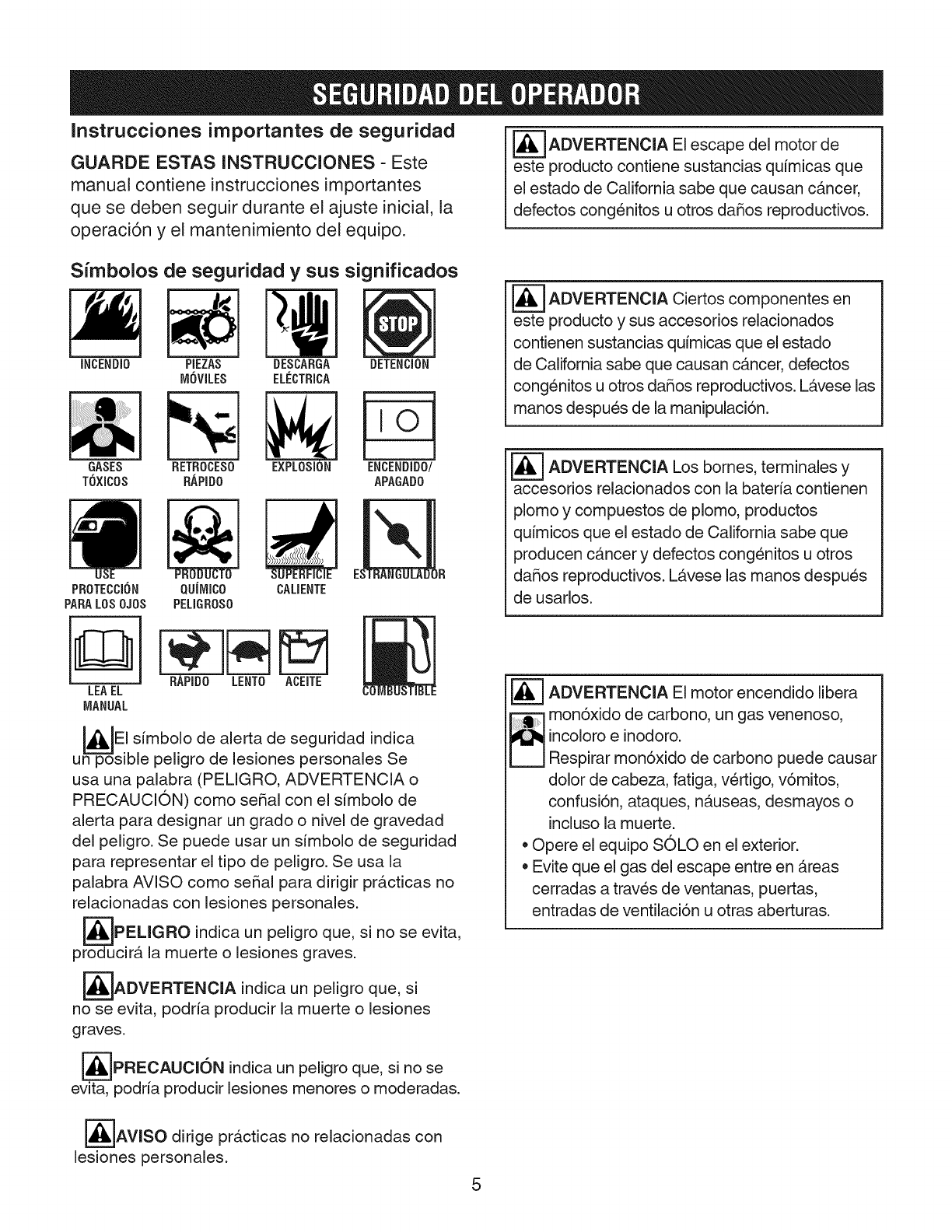
Instrucciones importantes de seguridad
GUARDE ESTAS INSTRUCCIONES - Este
manual contiene instrucciones importantes
que se deben seguir durante el ajuste inicial, la
operaci6n y el mantenimiento del equipo.
_--_ADVERTENCIA El del deescape motor
este producto contiene sustancias qu[micas que
el estado de California sabe que causan cancer,
defectos congenitos u otros dafios reproductivos.
Simbolos de seguridad y sus significados
INCENDI0
GASES
TOXICOS
PIEZAS
MOVILES
RETROCES0
BAPID0
DESCABGA DETENCION
ELECTRICA
EXPLOSION
IO
ENCENDIDO
APAGADO
PROTECCI{]N QUJMICO CALIENTE
PARALOSOJOS PELIGBOSO
_=7 ADVERTENCIA componentes en
Ciertos
este producto y sus accesorios relacionados
contienen sustancias qu[micas que el estado
de California sabe que causan cancer, defectos
congenitos u otros dafios reproductivos. L_,vese las
manos despues de la manipulaci6n.
_---_ ADVERTENCIA bornes, y
Los terminales
accesorios relacionados con la bater[a contienen
plomo y compuestos de plomo, productos
qu[micos que el estado de California sabe que
producen cancer y defectos congenitos u otros
dafios reproductivos. L_,vese las manos despues
de usados.
LEA EL
MANUAL
BAPIDO LENTO ACEITE
I_JEI s[mbolo de alerta de indica
seguridad
un--=-Spsible peligro de lesiones personales Se
usa una palabra (PELIGRO, ADVERTENCIA o
PRECAUCION) como serial con el s[mbolo de
alerta para designar un grado o nivel de gravedad
del peligro. Se puede usar un s[mbolo de seguridad
para representar el tipo de peligro. Se usa la
palabra AVISO como serial para dirigir pr&cticas no
relacionadas con lesiones personales.
_--TPELIGRO indica un peligro que, si no se evita,
producir& la muerte o lesiones graves.
_ADVERTENClA indica un peligro que, si
no se evita, podria producir la muerte o lesiones
graves.
_=]PRECAUCI6N indica un peligro que, si no se
evita, podria producir lesiones menores o moderadas.
[_--'=_ADVERTENCIA El motor encendido libera
_ on6xido de carbono, un gas venenoso,
incoloro einodoro.
Respirar mon6xido de carbono puede causar
dolor de cabeza, fatiga, vertigo, v6mitos,
confusi6n, ataques, n_,useas, desmayos o
incluso la muerte.
• Opere el equipo SOLO en el exterior.
Evite que el gas del escape entre en Areas
cerradas a traves de ventanas, puertas,
entradas de ventilaci6n u otras aberturas.
_AVlSO dirige pr&cticas no relacionadas con
lesiones personales.
5
ADVERTENClA: iEsta m&quina cortacesped es capaz de amputar manos y pies y puede lanzar objetos
que pueden causar lesiones y daSos! Si no se cumplen las siguientes instrucciones de SEGURIDAD, el
operador o los transeL_ntes podrian sufrir lesiones graves o la muerte. El propietario de la m&quina deber&
comprender estas instrucciones y permitir& utilizar la m&quina L_nicamente a personas que comprendan
estas instrucciones. Todas las personas que hagan funcionar la m&quina deber&n ser due6as de s[ mental y
fisicamente y no deber&n hallarse bajo la infiuencia de ningun tipo de sustancias que puedan deteriorar sus
capacidades visuales, su destreza o capacidad de juicio.
Protecci6n ala infancia
Pueden ocurrir accidentes graves si el usuario no esta
atento ante la presencia de niBos. Los niBos suelen
sentirse atraidos por la unidad y por la actividad del
cortacesped. Nunca de por hecho que los niSos vayan a
permanecer en el L_ltimolugar en el que los vio.
1. MANTENGA a los niBos fuera del Area de corte y bajo
la vigilancia atenta de algOn adulto responsable.
2. NO PERMITA que niSos ni otros se monten en la
maquina, en sus accesorios ni en el equipo remolcado
(incluso con las cuchillas DESCONECTADAS).
Podrian caerse y resultar gravemente heridos.
3. PERMITA 0nicamente que adultos y adolescentes
responsables con capacidad de juicio madura y bajo la
supervisi6n cercana de un adulto utilicen la maquina.
4. NO opere las cuchillas marcha atras. DETENGA LAS
CUCHILLAS. MIRE detras y debajo de Ud. antes de
retroceder y antes de retroceder y mientras Io haga
por si hay niBos, animales domesticos u otros peligros.
5. PONGA ESPECIAL CUIDADO al acercarse a esquinas
cerradas, arbustos, arboles u otros objetos que
puedan obstaculizar la visi6n.
C6mo evitar que vuelque
Las pendientes son un factor de gran perdida en los casos
de perdida de control y en los accidentes en los que
vuelca el cortacesped, que pueden resultar en lesiones
graves o incluso la muerte. Todas las pendientes requieren
mayor PRECAUCION. Si no puede ir hacia atras sobre una
pendiente con el cortacesped, o no se siente seguro sobre
la pendiente, NO corte el cesped en la misma. Ponga
el mayor cuidado con los recogedores de hierba y otros
elementos anexos: afectan al manejo y a la estabilidad de
la maquina. Consulte la Guia de trabajo en pendientes que
encontrara al final de esta secci6n.
1. NO opere la maquina en pendientes que excedan
los 10 grados, Io que equivale a 1,1 m (3,5 pies)
verticalmente por cada 6,1 m (20 pies) horizontalmente.
2. DESCONECTE las cuchillas cuando se desplace
cuesta arriba. Utilice una velocidad lenta evitando
giros bruscos.
3. NO maneje la maquina hacia delante y hacia atras
en medio de las pendientes. Manejela hacia arriba y
hacia abajo. Practique sobre las pendientes con las
cuchillas desconectadas.
4. EVITE arrancar, detenerse, o girar en pendientes. Si la
maquina se detiene mientras sube o los neumaticos
pierden tracci6n, DESCONECTE las cuchillas y
retroceda lentamente en linea recta hacia abajo.
5. ESTE ALERTA ante la presencia de hoyos y otros
peligros ocultos. La hierba alta puede ocultar obstaculos.
Mantengase lejos de cunetas, deslaves, alcantarillas,
cercas y objetos que puedan salir proyectados.
6. MANTENGA UNA DISTANCIA DE SEGURIDAD
minima de 0,9 metros (3 pies) de separaci6n desde el
borde de zanjas y otros desniveles. La maquina podria
volcar si se mete una parte en un desnivel.
7. Comience siempre a moverse hacia delante
lentamente y con precauci6n.
8. Manipule pesos o un transportador de carga con peso
segOn las instrucciones proporcionadas junto con
el recolector de hierba. NO MANEJE la maquina en
pendientes que excedan los 10 grados.
9. NO coloque su pie en el suelo para intentar estabilizar
la maquina.
10. NO utilice el cortacesped sobre hierba hOmeda. La
reducci6n de tracci6n puede causar deslizamiento.
11. Escoja una velocidad Io suficientemente baja de
manera tal que no tenga que detenerse ni hacer
cambios en pendientes. Los neumaticos pueden
perder tracci6n en las pendientes incluso cuando los
frenos funcionen debidamente.
12. NO maneje la maquina en circunstancias en que la
tracci6n, la direcci6n o la estabilidad sean dudosas.
13. Siempre mantenga la maquina con un cambio al bajar
pendientes. NO utilice el punto muerto (ni libere el
hidro-rodamiento) para bajar una pendiente.
Antes de cortar el c_sped
1. Lea, comprenda y siga las instrucciones y advertencias
en este manual y las indicadas sobre la maquina, el
motor y sus accesorios. Conozca los controles y el uso
a,propiado de la maquina antes de comenzar.
2. Unicamente deben hacer funcionar la maquina
personas maduras y responsables y s61o despues de
la adecuada instrucci6n.
3. Los datos indican que operadores de 60 o mas a_os
estan implicados en un amplio porcentaje de lesiones
relacionadas con el uso de tractores cortacesped.
Estos operadores deberan evaluar su capacidad de
utilizar la unidad de manera Io suficientemente segura
como para protegerse a si mismos y a los demas
frente a graves lesiones.
4. Manipule el combustible con especial precauci6n.
Los combustibles son inflamables y sus vapores,
explosivos. Utilice un recipiente de combustible
homologado. NO retire la tapa del combustible ni
aBada combustible con el motor en march& A_ada
combustible L_nicamente en exteriores y con el motor
parado y fr[o. Limpie el carburante derramado sobre la
maquina. NO fume.
5. Practique el manejo de la maquina con LAS
CUCHILLAS DESCONECTADAS para aprender los
controles y desarrollar destrezas.
6. Revise la zona de cesped que se va a cortar y retire
objetos como juguetes, cables, piedras, ramas y
otros elementos que puedan causar lesiones si
6
son lanzados por la cuchilla o interfieren con el
funcionamiento del cortacesped.
7. Mantenga personas y animales domesticos lejos
de la zona donde va a cortar el cesped. DETENGA
inmediatamente las cuchillas, DETENGA el motor
y DETENGA el cortacesped en caso de que alguna
persona entre en la zona.
8. Compruebe con frecuencia el adecuado
funcionamiento y ubicaci6n de protecciones,
deflectores, interruptores, controles de la cuchilla y
otros dispositivos de seguridad.
9. Aseg0rese de que todas las calcomanfas de seguridad
sean claramente legibles. Reemplacelas si estan
dahadas.
10. Cuando corte el cesped, protejase con gafas de
seguridad, mascarilla anti-polvo, pantalones largos y
calzados s61idos.
11. Debe saber c6mo DETENER rapidamente las
cuchillas y el motor para prepararse ante cualquier
emergencia.
12. Extreme la precauci6n cuando cargue o descargue la
m_.quina en un remolque o cami6n.
13. Compruebe con frecuencia los componentes del
recogedor de hierba en busca de se_ales de desgaste
o deterioro y reemplacelos, seg0n sea necesario, para
evitar las lesiones producidas pot el lanzamiento de
objetos a traves de puntos debiles o desgastados.
IVlanipulaci6n segura de la gasolina
Para evitar lesiones personales o dahos en los bienes,
extreme la precauci6n cuando manipule gasolina. La
gasolina es extremadamente inflamable y sus vapores
son explosivos.
1. Apague cigarrillos, puros, pipas y cualquier otra fuente
que pueda provocar incendios.
2. Utilice s61o un recipiente de combustible homologado.
3. NO retire la tapa del combustible ni a_ada combustible
con el motor en marcha. Deje que el motor se enfrfe
antes de reponer el combustible.
4. NO reponga combustible en la maquina en espacios
cerrados.
5. NO almacene la ma.quina ni el recipiente de
combustible en interiores donde haya llamas
expuestas, chispas ni luces pilotos como las de los
calentadores de agua u otros dispositivos.
6. NUNCA Ilene recipientes de combustible en el interior
de vehiculos ni sobre el lecho de un cami6n o remolque
con revestimientos de plb.stico. SitQe los recipientes
sobre el suelo, lejos del vehfculo, antes de Ilenarlos.
7. Retire del vehfculo o cami6n el equipamiento
alimentado por gasolina y reponga el combustible
sobre el suelo. Si ello no es posible, reponga el
combustible del equipo utilizando un contenedor
portatil y no con boquillas dosificadoras de gasolina.
8. NO arranque equipos alimentados pot gasolina en
vehfculos o remolques cerrados.
9. Mantenga la boquilla en contacto con el borde de la
abertura del dep6sito o recipiente de combustible en
todo momento hasta haber completado el Ilenado. NO
use un dispositivo para trabar y abrir boquillas.
10. Si se derrama combustible sobre la ropa, cambiese la
ropa de inmediato.
11. Nunca Ilene en exceso el dep6sito de combustible.
Vuelva a situar la tapa del combustible y ajOstela
firmemente.
Consideraciones generales de seguridad de
funcionamiento
1. Monte y desmonte la mb.quina desde el lado izquierdo.
Mantengase alejado del agujero de descarga en todo
momento.
2. Encienda el motor desde el asiento del operador.
AsegL_rese de que las cuchillas esten DESACTIVADAS
y de que este activado el freno de mano.
3. NO abandone la ma.quina con el motor en
funcionamiento. DETENGA el motor, DETENGA las
cuchillas, ACTIVE el freno y quite la Ilave antes de
abandonar el puesto del conductor.
4. NO maneje la mb.quina a no set que este correctamente
sentado con los pies en los apoyos o pedales.
5. DETENGA LAS CUCHILLAS y EL MOTOR y
asegOrese de que las cuchillas se hayan detenido
antes de quitar el recolector de cesped o antes de
desatascar el cortacesped para evitar la amputaci6n
de dedos o manos.
6. Las cuchillas deben estar DESCONECTADAS excepto
cuando se corte el cesped. Coloque las cuchillas en
la posici6n mas alta cuando este cortando sobre una
superficie desigual.
7. Mantenga las manos y los pies lejos de las cuchillas
en rotaci6n que estb.n debajo de la plataforma. NO
ponga el pie en el suelo mientras las CUCHILLAS
esten ACTWADAS o la mientras la maquina este en
movimiento.
8. NO maneje la mb.quina sin que el recolector de cesped
o los protectores esten correctamente colocados
yen funcionamiento. NO apunte la descarga hacia
personas, coches en transito, ventanas o puertas.
9. Reduzca la velocidad antes de realizar giros.
10. Tenga cuidado con el transito al cruzar o pasar cerca
de vias.
11. DETENGA la ma.quina inmediatamente despues de
golpear obstaculos. Inspeccione el cortacesped y
repare los da_os antes de volver a manejarlo.
12. Maneje la ma.quina s61o durante el dfa o con luz
artificial potente.
13. Mueva LENTAMENTE la palanca de mando (si la
tiene) para mantener el control durante cambios de
velocidad y de sentido.
14. NO haga funcionar el motor en zonas cerradas.
Los gases del tubo de escape del motor contienen
mon6xido de carbono, un veneno letal.
15. NO descargue materiales contra paredes ni
obstaculos. Los materiales pueden rebotar hacia el
operador.
16. Utilice 0nicamente accesorios aprobados por el
fabricante. Consulte las instrucciones del fabricante
para obtener informaci6n sobre el funcionamiento y la
instalaci6n de accesorios.
7
RemoJoar
1. Remolque solamente con una maquina que tenga
un enganche diseBado para remolque. NO sujete el
equipo remolcado a un lugar que no sea el punto de
enganche.
2. Siga las recomendaciones del fabricante respecto
a los limites de peso para equipos remolcados y
remolque en pendientes.
3. NO permita que nihos ni otras personas se suban al
equipo remolcado.
4. En pendientes, el peso del equipo remolcado puede
causar p@dida de tracci6n y p@dida de control.
5. Desplacese lentamente y deje una distancia extra para
poder detenerse.
6. Tenga CUIDADO cuando arrastre cargas. No Ileve m_.s
carga de la que pueda controlar con seguridad y sujete
las cargas a la placa de enganche segOn se especifica
en las instrucciones de los accesorios.
Seguridad de rnantenimiento
1. NO guarde el cortacesped ni el recipiente para el
combustible en lugares donde los vapores puedan
alcanzar una llama abierta, chispa o luz piloto como
la de los calentadores de agua, hornos, secadoras de
ropa u otros dispositivos que utilicen gas. Permita que
el motor se enfrie antes de almacenar la maquina en
un lugar cerrado. Guarde el contenedor o recipiente
para el carburante fuera del alcance de los niBos en un
lugar deshabitado.
2. Mantenga la maquina libre de cesped, hojas o
exceso de grasa para reducir el riesgo de incendio y
sobrecalentamiento del motor.
3. Cuando drene el dep6sito de combustible, drene
el combustible en el exterior hasta un recipiente
homologado y lejos de llamas expuestas.
4. Siempre procure una ventilaci6n adecuada cuando el
motor este en funcionamiento. Los gases del tubo de
escape del motor contienen mon6xido de carbono, un
veneno inodoro letal.
5. Desconecte el cable negativo (negro) de la bateria
antes de realizar el mantenimiento o cualquier
reparaci6n en la ma.quina. El motor de arranque puede
causar lesiones.
6. NO trabaje debajo de la ma.quina sin bloques de
seguridad.
7. Unicamente realice reparaciones y ajustes en el motor
cuando este se encuentre detenido. Retire el (los)
cable (s) de bujia del enchufe de la bujia y fije el (los)
cable (s)lejos del (los) enchufe (s) de la bujia.
9. NO cambie los ajustes de velocidad del regulador del
motor ni acelere en exceso el motor.
10. Las cuchillas del cortacesped son afiladas y
pueden producir cortes. Envuelva las cuchillas
o utilice gruesos guantes de cuero y extreme la
PRECAUCION cuando las manipule.
11. NO pruebe la existencia de chispas conectando la
bujia a tierra junto al orificio de la bujia; la bujia podria
encender la gasolina que sale del motor.
12. Mantenga o reemplace las etiquetas de seguridad e
instrucciones, segOn sea necesario.
8
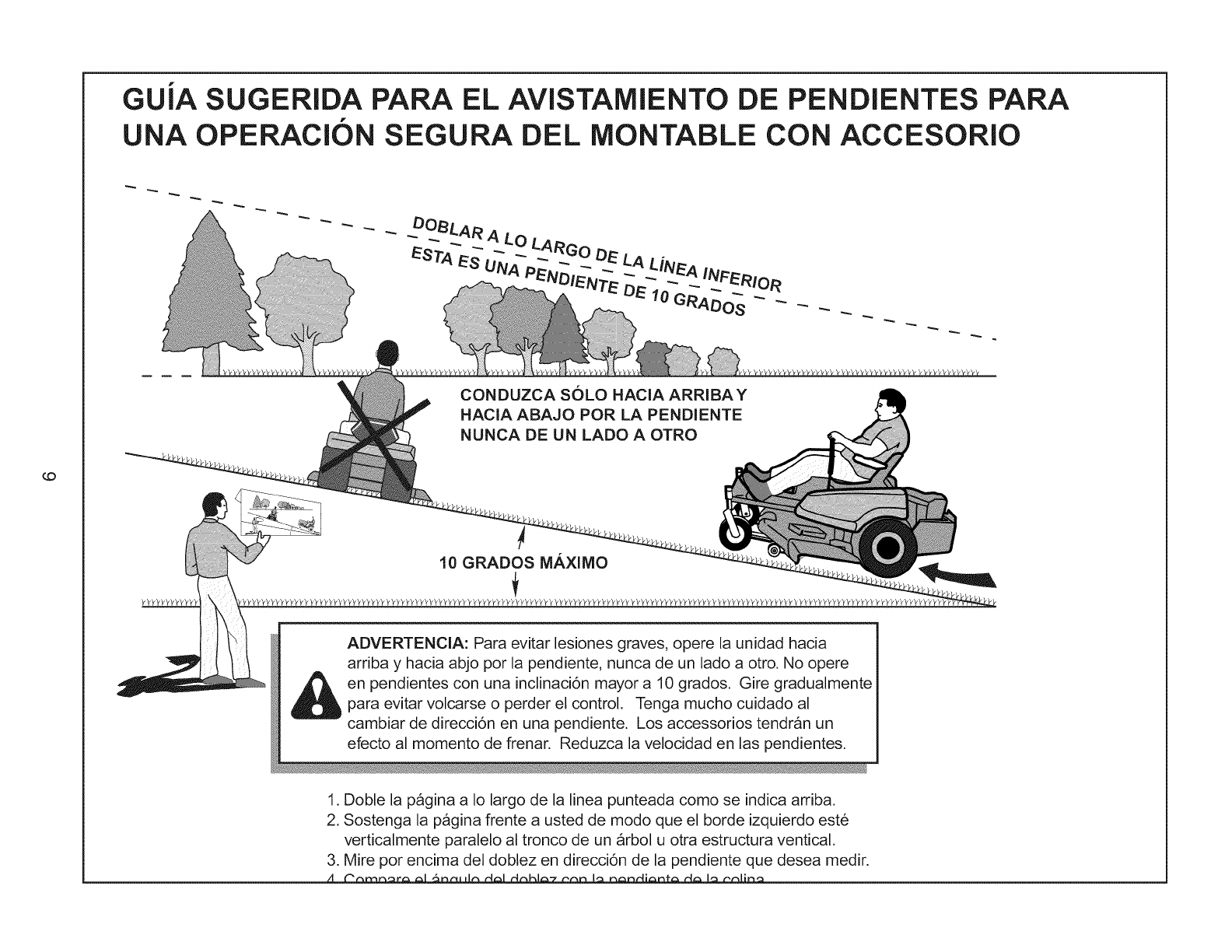
GUIA SUGERIDA PARA EL AVISTAMIENTO DE PENDIENTES PARA
UNA OPERACiON SEGURA DEL MONTABLE CON ACCESORIO
10
CONDUZCA SOLO HACIA ARRIBA Y
HACIA ABAJO POR LA PENDIENTE
NUNCA DE UN LADO A OTRO
LO
10 GRADOS M.AXIMO
ADVERTENCIA: Para evitar lesiones graves, opere la unidad hacia
arriba y hacia abjo por la pendiente, nunca de un lado a otro. No opere
en pendientes con una inclinaci6n mayor a 10 grados. Gire gradualmente
para evitar volcarse o perder el control. Tenga mucho cuidado al
cambiar de direcci6n en una pendiente. Los accessorios tendrb, n un
efecto al momento de frenar. Reduzca la velocidad en las pendientes.
1. Doble la pagina a Io largo de la linea punteada como se indica arriba.
2. Sostenga la pagina frente a usted de modo que el borde izquierdo este
verticalmente paralelo al tronco de un arbol u otra estructura ventical.
3. Mire por encima del doblez en direcciOn de la pendiente que desea medir.
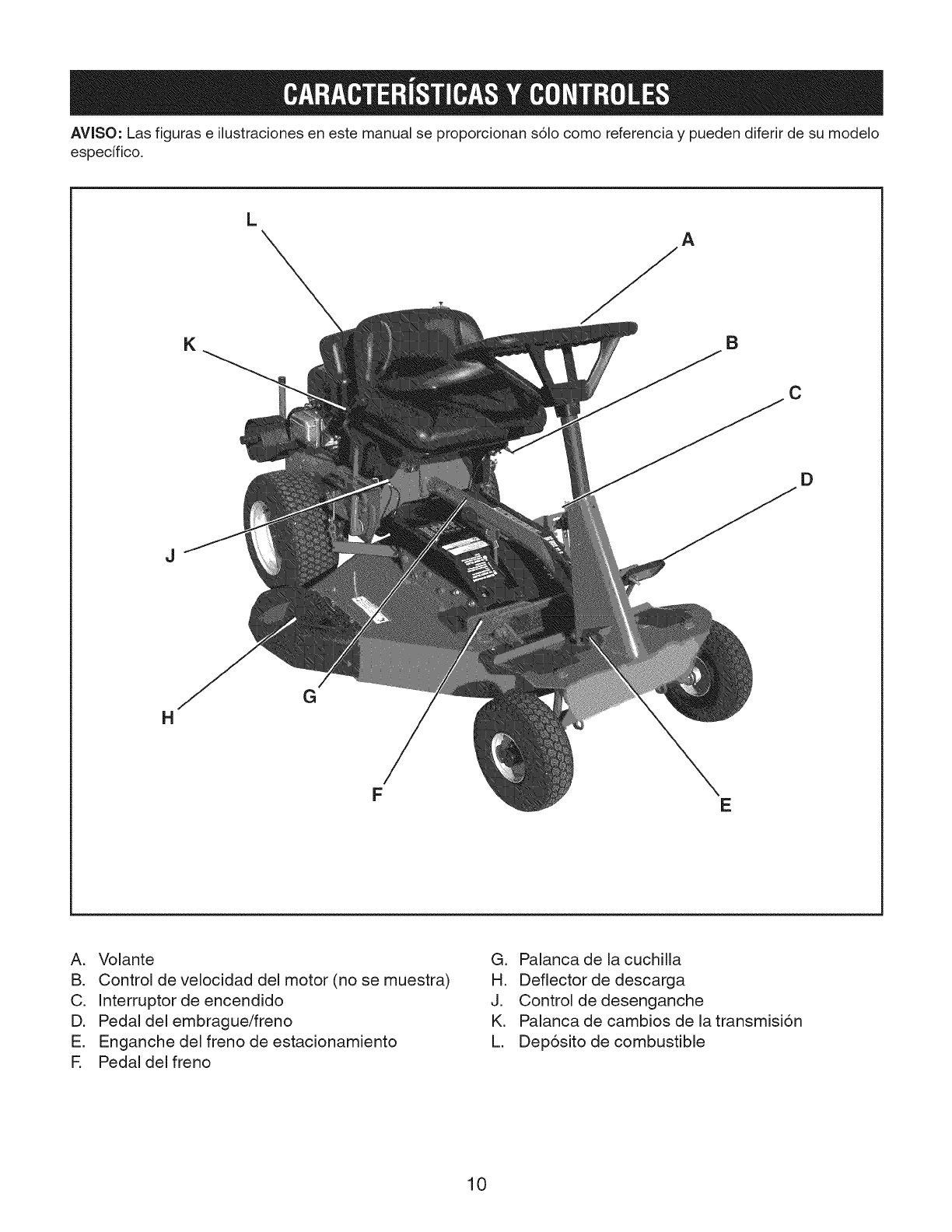
AVlSO: Las figuras e ilustraciones en este manual se proporcionan s61ocomo referencia y pueden diferir de su modelo
especifico.
J
14
K
L
G
F
A
B
E
C
D
A. Volante
B. Control de velocidad del motor (no se muestra)
C. Interruptor de encendido
D. Pedal del embrague/freno
E. Enganche del freno de estacionamiento
R Pedal del freno
G. Palanca de la cuchilla
H. Deflector de descarga
J. Control de desenganche
K. Palanca de cambios de la transmisi6n
L. Dep6sito de combustible
10
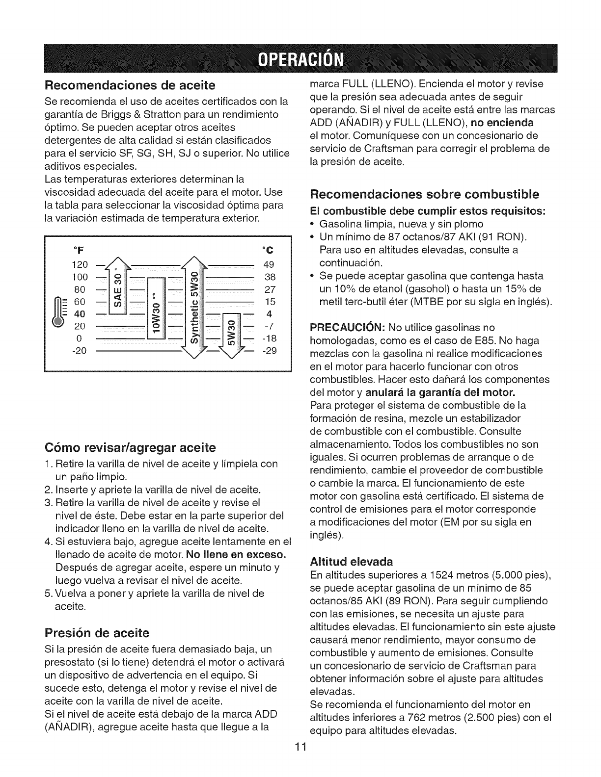
Recornendaciones de aceite
Se recomienda el uso de aceites certificados con la
garanfia de Briggs & Stratton para un rendimiento
optimo. Se pueden aceptar otros aceites
detergentes de alta calidad si estan clasificados
para el servicio SE SG, SH, SJ o superior. No utilice
aditivos especiales.
Las temperaturas exteriores determinan la
viscosidad adecuada del aceite para el motor. Use
la tabla para seleccionar la viscosidad optima para
la variacion estimada de temperatura exterior.
°F
120
100
80
60
40
20
0
-20
°c
oiiii
_ _ 38
_i;iiii 27
oiiiiii_ 15
@ iiii_ -- 4
iiii
>_i_ii =18
-29
C6rno revisar/agregar aceite
1. Retire la varilla de nivel de aceite y limpiela con
un patio limpio.
2. Inserte y apriete la varilla de nivel de aceite.
3. Retire la varilla de nivel de aceite y revise el
nivel de este. Debe estar en la parte superior del
indicador Ileno en la varilla de nivel de aceite.
4. Si estuviera bajo, agregue aceite lentamente en el
Ilenado de aceite de motor. No Ilene en exceso.
Despues de agregar aceite, espere un minuto y
luego vuelva a revisar el nivel de aceite.
5. Vuelva a poner y apriete la varilla de nivel de
aceite.
Presi6n de aceite
Si la presion de aceite fuera demasiado baja, un
presostato (si Io tiene) detendra el motor o activara
un dispositivo de advertencia en el equipo. Si
sucede esto, detenga el motor y revise el nivel de
aceite con la varilla de nivel de aceite.
Si el nivel de aceite esta debajo de la marca ADD
(AI_IADIR), agregue aceite hasta que Ilegue ala
marca FULL (LLENO). Encienda el motor y revise
que la presion sea adecuada antes de seguir
operando. Si el nivel de aceite esta entre las marcas
ADD (ANADIR) y FULL (LLENO), no encienda
el motor. Comuniquese con un concesionario de
servicio de Craftsman para corregir el problema de
la presi6n de aceite.
Recornendaciones sobre combustible
El combustible debe cumplir estos requisitos:
= Gasolina limpia, nueva y sin plomo
• Un minimo de 87 octanos/87 AKI (91 RON).
Para uso en altitudes elevadas, consulte a
continuaci6n.
• Se puede aceptar gasolina que contenga hasta
un 10% de etanol (gasohol) o hasta un 15% de
metil terc=butil eter (MTBE por su sigla en ingles).
PRECAUCI()N: No utilice gasolinas no
homologadas, como es el caso de E85. No haga
mezclas con la gasolina ni realice modificaciones
en el motor para hacerlo funcionar con otros
combustibles. Hacer esto datar& los componentes
del motor y anulara la garantia del motor.
Para proteger el sistema de combustible de la
formacion de resina, mezcle un estabilizador
de combustible con el combustible. Consulte
almacenamiento. Todos los combustibles no son
iguales. Si ocurren problemas de arranque o de
rendimiento, cambie el proveedor de combustible
o cambie la marca. El funcionamiento de este
motor con gasolina est& certificado. El sistema de
control de emisiones para el motor corresponde
a modificaciones del motor (EM por su sigla en
ingles).
AItitud elevada
En altitudes superiores a 1524 metros (5.000 pies),
se puede aceptar gasolina de un minimo de 85
octanos/85 AKI (89 RON). Para seguir cumpliendo
con las emisiones, se necesita un ajuste para
altitudes elevadas. El funcionamiento sin este ajuste
causar& menor rendimiento, mayor consumo de
combustible y aumento de emisiones. Consulte
un concesionario de servicio de Craftsman para
obtener informacion sobre el ajuste para altitudes
elevadas.
Se recomienda el funcionamiento del motor en
altitudes inferiores a 762 metros (2.500 pies) con el
equipo para altitudes elevadas.
11
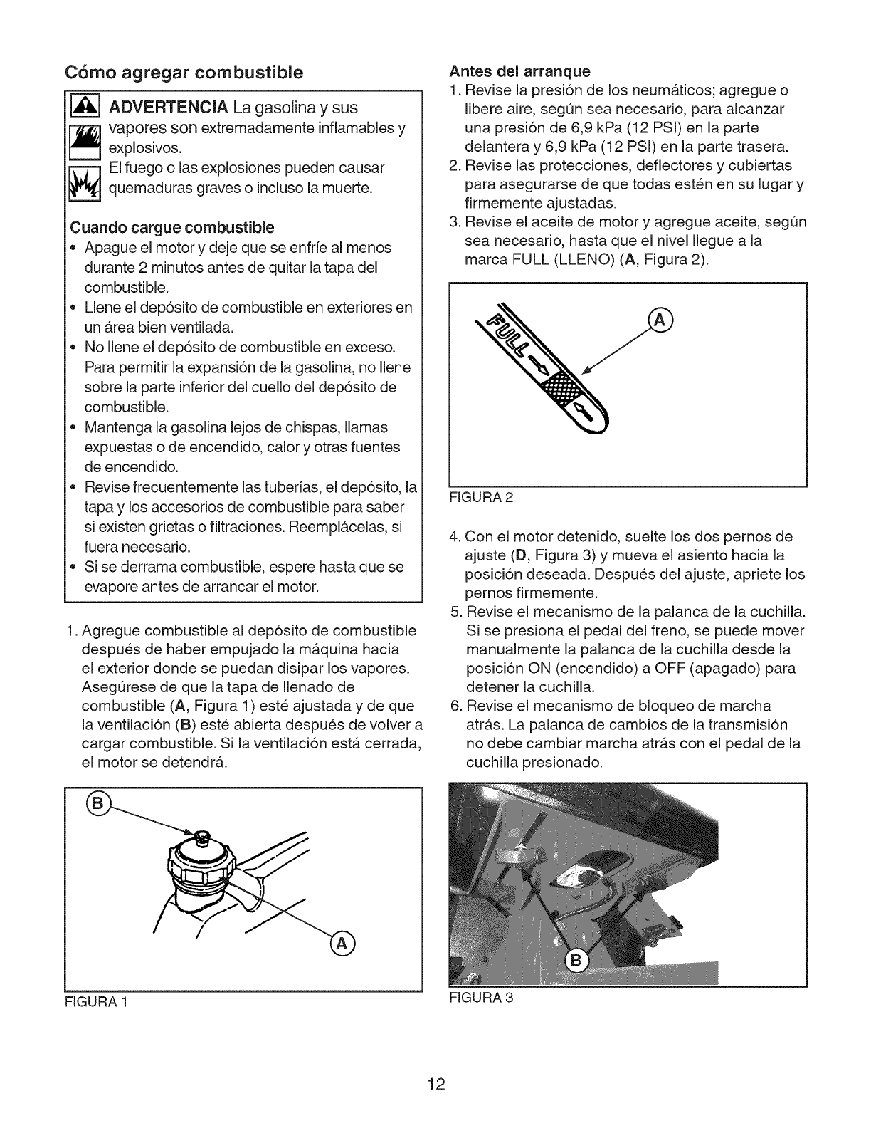
C6mo agregar combustible
ADVERTENClA La gasolina y sus
vapores son extremadamente inflamables y
explosivos.
_,_ l fuego o las explosiones pueden causar
quemaduras graves o incluso la muerte.
Cuando cargue combustible
= Apague el motor y deje que se enfrie al menos
durante 2 minutos antes de quitar la tapa del
combustible.
• Llene el dep6sito de combustible en exteriores en
un b,rea bien ventilada.
No Ilene el dep6sito de combustible en exceso.
Para permitir la expansi6n de la gasolina, no llene
sobre la parte inferior del cuello del dep6sito de
combustible.
Mantenga la gasolina lejos de chispas, llamas
expuestas o de encendido, calory otras fuentes
de encendido.
Revise frecuentemente las tuberfas, el dep6sito, la
tapa y los accesorios de combustible para saber
si existen grietas o filtraciones. Reemplb.celas, si
fuera necesario.
Si se derrama combustible, espere hasta que se
evapore antes de arrancar el motor.
1. Agregue combustible al dep6sito de combustible
despues de haber empujado la m&quina hacia
el exterior donde se puedan disipar los vapores.
Asegurese de que la tapa de Ilenado de
combustible (A, Figura 1) este ajustada y de que
la ventilaci6n (B) este abierta despues de volver a
cargar combustible. Si la ventilaci6n est& cerrada,
el motor se detendr&.
Antes del arranque
1. Revise la presi6n de los neum&ticos; agregue o
libere aire, segQn sea necesario, para alcanzar
una presi6n de 6,9 kPa (12 PSi) en la parte
delantera y 6,9 kPa (12 PSi) en la parte trasera.
2. Revise las protecciones, deflectores y cubiertas
para asegurarse de que todas esten en su lugar y
firmemente ajustadas.
3. Revise el aceite de motor y agregue aceite, segL_n
sea necesario, hasta que el nivel Ilegue a la
marca FULL (LLENO) (A, Figura 2).
FIGURA 2
4. Con el motor detenido, suelte los dos pernos de
ajuste (D, Figura 3) y mueva el asiento hacia la
posici6n deseada. Despues del ajuste, apriete los
pernos firmemente.
5. Revise el mecanismo de la palanca de la cuchilla.
Si se presiona el pedal del freno, se puede mover
manualmente la palanca de la cuchilla desde la
posici6n ON (encendido) a OFF (apagado) para
detener la cuchilla.
6. Revise el mecanismo de bloqueo de marcha
atr&s. La palanca de cambios de la transmisi6n
no debe cambiar marcha atr&s con el pedal de la
cuchilla presionado.
FIGURA 1
12
FIGURA 3
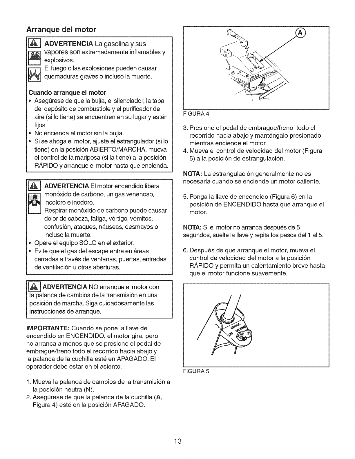
Arranque del motor
|ADVERTENCIA La gasolina y sus
_ apores son extremadamente infiamables y
explosives.
EI fuego o las explosiones pueden causar
quemaduras graves o incluso la muerte.
Cuando arranque el motor
• AsegQrese de que la bujfa, el silenciador, la tapa
del dep6sito de combustible y el purificador de
aire (si Io tiene) se encuentren en su lugar y esten
flies.
No encienda el motor sin la bujfa.
Si se ahoga el motor, ajuste el estrangulador (si Io
tiene) en la posici6n ABIERTO/MARCHA, mueva
el control de la mariposa (si la tiene) a la posici6n
R,&PIDO y arranque el motor hasta que encienda.
@
@
ADVERTENClA El motor encendido Iibera
mon6xido de carbono, un gas venenoso,
incoloro e inodoro.
Respirar mon6xido de carbono puede causar
dolor de cabeza, fatiga, vertigo, v6mitos,
confusi6n, ataques, nb.useas, desmayos o
incluso la muerte.
Opere el eqwpo SOLO en el exterior.
Evite que el gas del escape entre en Areas
cerradas a traves de ventanas, puertas, entradas
de ventilaci6n u otras aberturas.
ADVERTENClA arranque motor con
NO el
la palanca de cambios de la transmisi6n en una
posici6n de marcha. Siga cuidadosamente las
instrucdones de arranque.
FIGURA 4
3. Presione el pedal de embrague/freno todo el
recorrido hacia abajo y mantengalo presionado
mientras enciende el motor.
4. Mueva el control de velocidad del motor (Figura
5) a la posicion de estrangulaci6n.
NOTA: La estrangulaci6n generalmente no es
necesaria cuando se enciende un motor caliente.
5. Ponga la Ilave de encendido (Figura 6) en la
posicion de ENCENDIDO hasta que arranque el
motor.
NOTA: Si el motor no arranca despues de 5
segundos, suelte la Ilave y repita los pasos del 1 al 5.
6. Despues de que arranque el motor, mueva el
control de velocidad del motor a la posicion
RAPIDO y permita un calentamiento breve hasta
que el motor funcione suavemente.
IMPORTANTE: Cuando se pone la Ilave de
encendido en ENCENDIDO, el motor gira, pero
no arranca a menos que se presione el pedal de
embrague/freno todo el recorrido hacia abajo y
la palanca de la cuchilla este en APAGADO. El
operador debe estar en el asiento.
1. Mueva la palanca de cambios de la transmision a
la posicion neutra (N).
2. Asegurese de que la palanca de la cuchilla (A,
Figura 4) este en la posicion APAGADO.
FIGURA 5
13
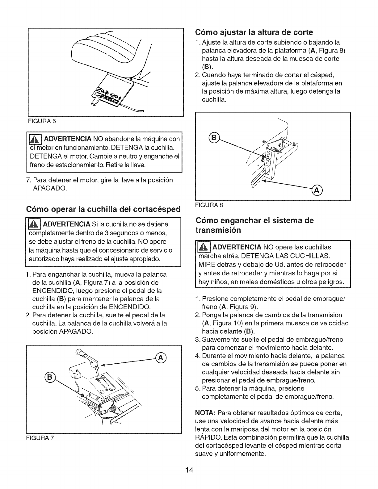
/
/
C6mo ajustar la altura de torte
1. Ajuste la altura de corte subiendo o bajando la
palanca elevadora de la plataforma (A, Figura 8)
hasta la altura deseada de la muesca de corte
(B).
2. Cuando haya terminado de cortar el cesped,
ajuste la palanca elevadora de la plataforma en
la posicion de mb.xima altura, luego detenga la
cuchilla.
FIGURA 6
e_]m ADVERTENCIA NO abandone la m_.quina con
otor en funcionamiento. DETENGA la cuchilla.
DETENGA el motor. Cambie a neutro y enganche el
freno de estacionamiento. Retire la Ilave.
7. Para detener el motor, gire la Ilave ala posicion
APAGADO.
C6mo operar la cuchilla del cortac_sped
[_ ADVERTENCIA Si la cuchilla detiene
no se
completamente dentro de 3 segundos o menos,
se debe ajustar el freno de la cuchilla. NO opere
lamb, quina hasta que el concesionario de servicio
autorizado haya realizado el ajuste apropiado.
1. Para enganchar la cuchilla, mueva la palanca
de la cuchilla (A, Figura 7) a la posicion de
ENCENDIDO, luego presione el pedal de la
cuchilla (B) para mantener la palanca de la
cuchilla en la posicion de ENCENDIDO.
2. Para detener la cuchilla, suelte el pedal de la
cuchilla. La palanca de la cuchilla volvera, a la
posicion APAGADO.
FIGURA 7
/
FIGURA 8
C6mo enganchar el sistema de
transmisi6n
_---=1ADVERTENCIA NO las cuchillasopere
marcha atrb.s. DETENGA LAS CUCHILLAS.
MIRE detrb.s y debajo de Ud. antes de retroceder
y antes de retroceder y mientras Io haga por si
hay niSos, animales domesticos u otros peligros.
1. Presione completamente el pedal de embrague/
freno (A, Figura 9).
2. Ponga la palanca de cambios de la transmision
(A, Figura 10) en la primera muesca de velocidad
hacia delante (B).
3. Suavemente suelte el pedal de embrague/freno
para comenzar el movimiento hacia delante.
4. Durante el movimiento hacia delante, la palanca
de cambios de la transmision se puede poner en
cualquier velocidad deseada hacia delante sin
presionar el pedal de embrague/freno.
5. Para detener la ma.quina, presione
completamente el pedal de embrague/freno.
NOTA: Para obtener resultados optimos de corte,
use una velocidad de avance hacia delante mb,s
lenta con la mariposa del motor en la posicion
RAPIDO. Esta combinacion permitirA que la cuchilla
del cortacesped levante el cesped mientras corta
suave y uniformemente.
14
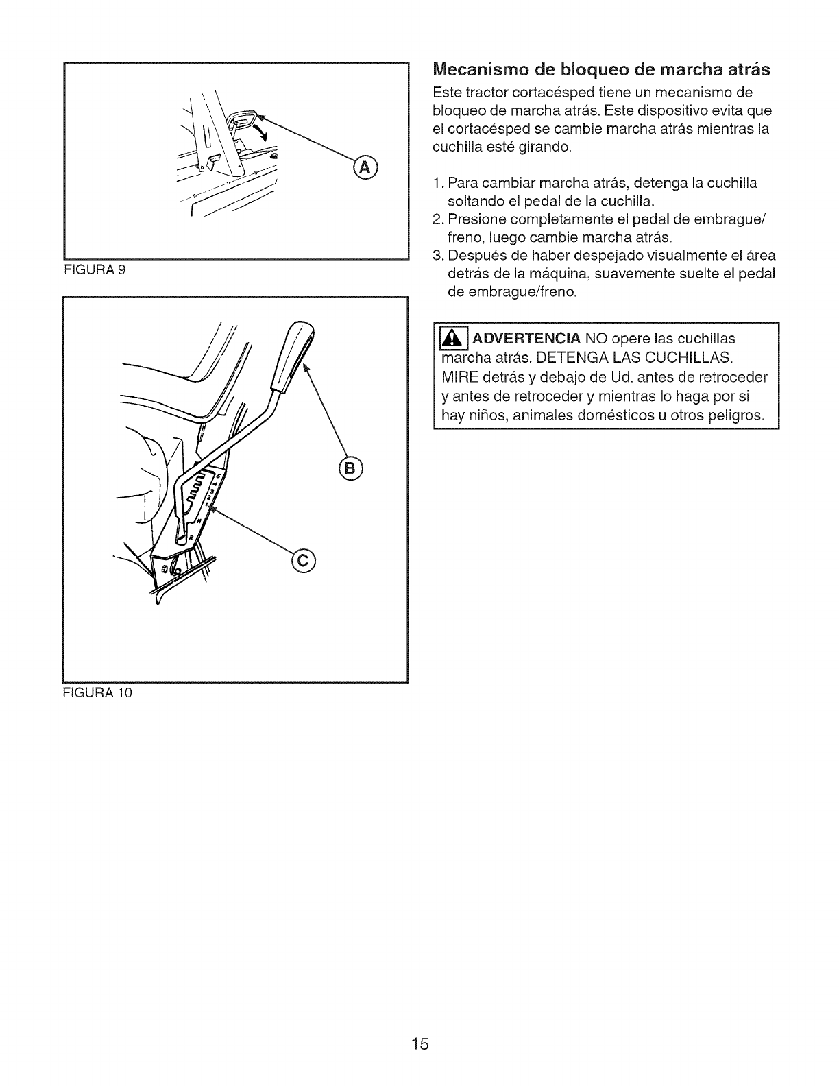
FIGURA 9
tII
©
IVlecanisrno de bloqueo de marcha atrbs
Este tractor cortacesped tiene un mecanismo de
bloqueo de marcha atr&s. Este dispositivo evita que
el cortacesped se cambie marcha atras mientras la
cuchilla este girando.
1. Para cambiar marcha atr&s, detenga la cuchilla
soltando el pedal de la cuchilla.
2. Presione completamente el pedal de embrague/
freno, luego cambie marcha atr&s.
3. Despues de haber despejado visualmente el &rea
detr&s de la m&quina, suavemente suelte el pedal
de embrague/freno.
_---'] ADVERTENCIA NO las cuchillasopere
marcha atras. DETENGA LAS CUCHILLAS.
MIRE detrb.s y debajo de Ud. antes de retroceder
y antes de retroceder y mientras Io haga pot si
hay ni_os, animales domesticos u otros peligros.
FIGURA 10
15
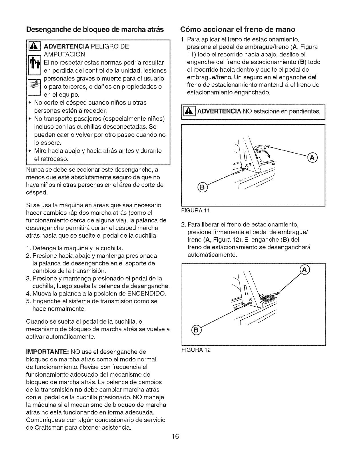
Desenganche de bloqueo de rnarcha atr_s
ADVERTENCIA PELIGRO DE
AM PUTACION
El no respetar estas normas podrfa resultar
en perdida del control de la unidad, lesiones
personales graves o muerte para el usuario
o para terceros, o daSos en propiedades o
en el eqwpo.
No corte el cesped cuando niSos u otras
personas esten alrededor.
No transporte pasajeros (especialmente niSos)
incluso con las cuchillas desconectadas. Se
pueden caer o volver por otro paseo cuando no
Io espere.
Mire hacia abajo y hacia atr_,s antes y durante
el retroceso.
Nunca se debe seleccionar este desenganche, a
menos que este absolutamente seguro de que no
haya niSos ni otras personas en el &rea de corte de
cesped.
Si se usa la maquina en &reas que sea necesario
hacer cambios r&pidos marcha atr&s (como el
funcionamiento cerca de alguna via), la palanca de
desenganche permitira, cortar el cesped marcha
atr&s hasta que se suelte el pedal de la cuchilla.
1. Detenga Ja mAquina y Ja cuchiJJa.
2. Presione hacia abajo y mantenga presionada
la palanca de desenganche en el soporte de
cambios de la transmisi6n.
3. Presione y mantenga presionado el pedal de la
cuchilla, luego suelte la palanca de desenganche.
4. Mueva la palanca a la posici6n de ENCENDIDO.
5. Enganche el sistema de transmisi6n como se
hace normalmente.
Cuando se suelta el pedal de la cuchilla, el
mecanismo de bloqueo de marcha atrAs se vuelve a
activar automa.ticamente.
llVIPORTANTE: NO use el desenganche de
bloqueo de marcha atr&s como el modo normal
de funcionamiento. Revise con frecuencia el
funcionamiento adecuado del mecanismo de
bloqueo de marcha atr&s. La palanca de cambios
de la transmisi6n no debe cambiar marcha atr&s
con el pedal de la cuchilla presionado. NO maneje
la maquina si el mecanismo de bloqueo de marcha
atra.s no estA funcionando en forma adecuada.
Comuniquese con algt3n concesionario de servicio
de Craftsman para obtener asistencia.
16
C6rno accionar el freno de rnano
1. Para aplicar el freno de estacionamiento,
presione el pedal de embrague/freno (A, Figura
11 ) todo el recorrido hacia abajo, deslice el
enganche del freno de estacionamiento (B) todo
el recorrido hacia dentro y suelte el pedal de
embrague/freno. Un seguro en el enganche del
freno de estacionamiento mantendr& el freno de
estacionamiento enganchado.
_--_ ADVERTENCIA NO estacione en pendientes.
FIGURA 11
2. Para liberar el freno de estacionamiento,
presione firmemente el pedal de embrague/
freno (A, Figura 12). El enganche (B) del
freno de estacionamiento se desenganchar&
automa.ticamente.
FIGURA 12
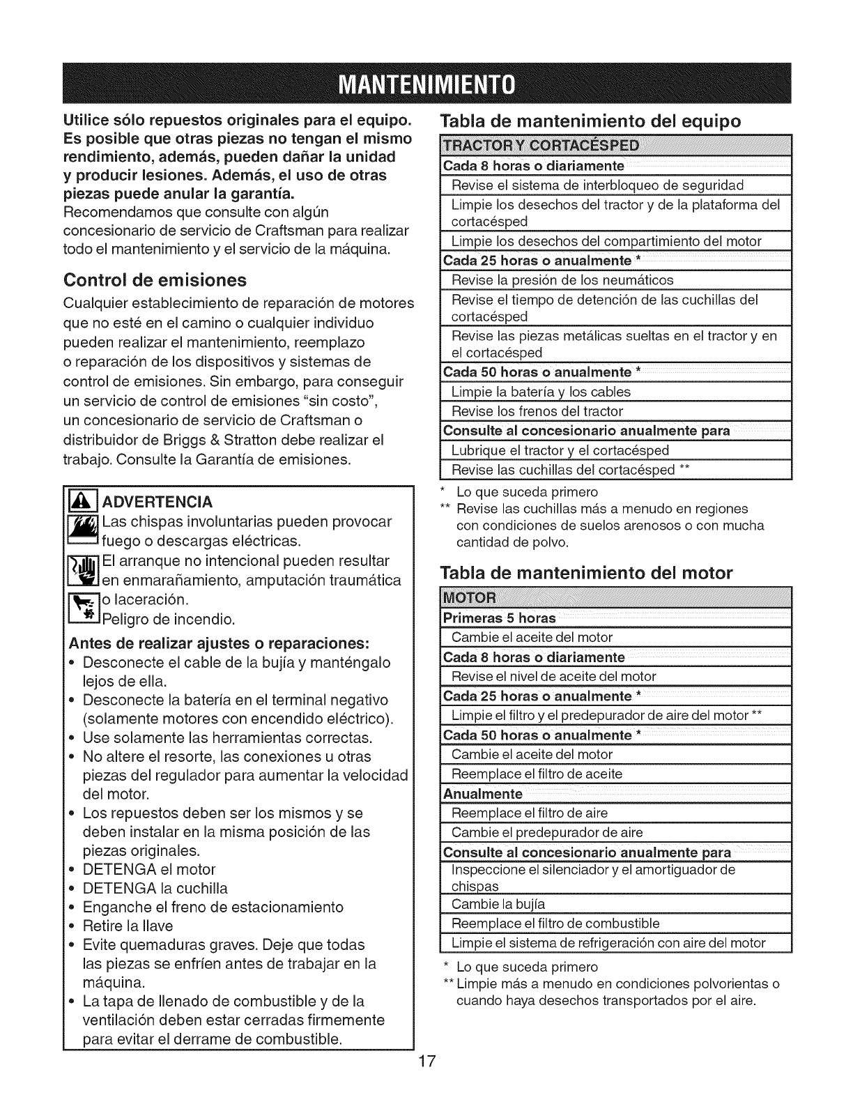
Utilice s61o repuestos originales para el equipo.
Es posible que otras piezas no tengan el mismo
rendimiento, ademas, pueden dahar la unidad
y producir lesiones. Ademas, el uso de otras
piezas puede anular la garantia.
Recomendamos que consulte con algL_n
concesionario de servicio de Craftsman para realizar
todo el mantenimiento y el servicio de la maquina.
Control de emisiones
Cualquier establecimiento de reparacion de motores
que no este en el camino o cualquier individuo
pueden realizar el mantenimiento, reemplazo
o reparaci6n de los dispositivos y sistemas de
control de emisiones. Sin embargo, para conseguir
un servicio de control de emisiones "sin costo",
un concesionario de servicio de Craftsman o
distribuidor de Briggs & Stratton debe realizar el
trabajo. Consulte la Garantia de emisiones.
_-7 ADVERTENCIA
Las chispas involuntarias pueden provocar
fuego o descargas electricas.
El arranque no intencional pueden resultar
en enmaraSamiento, amputaci6n traumb.tica
o laceracidn.
Peligro de incendio.
Antes de realizar ajustes o reparaciones:
*Desconecte el cable de la bujia y mantengalo
lejos de ella.
*Desconecte la bateria en el terminal negativo
(solamente motores con encendido electrico).
*Use solamente las herramientas correctas.
*No altere el resorte, las conexiones u otras
piezas del regulador para aumentar la velocidad
del motor.
*Los repuestos deben ser los mismos y se
deben instalar en la misma posici6n de las
piezas originales.
*DETENGAel motor
*DETENGA la cuchilla
*Enganche el freno de estacionamiento
*Retire la Ilave
*Evite quemaduras graves. Deje que todas
las piezas se enfrien antes de trabajar en la
maquina.
*Latapade Ilenado de combustible y de la
ventilaci6n deben estar cerradas firmemente
para evitar el derrame de combustible.
Tabla de mantenimiento del equipo
Carla 8 horas o diariamente
Revise el sistema de interbloqueo de seguridad
Limpie los desechos del tractor y de la plataforma del
cortacesped
Limpie los desechos del compartimiento del motor
Carla 25 horas o anualmente *
Revise la presi6n de los neumAticos
Revise el tiempo de detenci6n de las cuchillas del
cortacesped
Revise las piezas metAlicas sueltas en el tractor yen
el cortacesped
Carla 50 horas o anualmente *
Limpie la baterfa y los cables
Revise los frenos del tractor
Consulte al conceslonario anualmente para
Lubrique el tractor y el cortacesped
Revise las cuchillas del cortacesped **
• Lo que suceda primero
•* Revise las cuchillas mb.s a menudo en regiones
con condiciones de suelos arenosos o con mucha
cantidad de polvo.
Tabla de mantenimiento del motor
Primeras 5horas ....
Cambie el aceite del motor
Carla 8 horas o diariamente
Revise el nivel de aceite del motor
,k
Carla 25 h0ras o anualmente
Limpie el filtro y el predepurador de aire del motor **
Caaa 50 horas O anualmente *
Cambie el aceite del motor
Reemplace el filtro de aceite
Anualrnente
Reemplace el filtro de aire
Cambie el predepurador de aire
Consulte al concesionario anualmente para
Inspeccione el silenciador y el amortiguador de
_as
Cambie la bujia
Reemplace el filtro de combustible
Limpie el sistema de refrigeraci6n con aire del motor
* Lo que suceda primero
** Limpie mas a menudo en condiciones polvorientas o
cuando haya desechos transportados pot el aire.
17
Verificaci6n del sistema de bloqueo de
seguridad
_--'] ADVERTENCIA Si la cuchilla detiene
no se
completamente dentro de 3 segundos o menos,
se debe ajustar el freno de la cuchilla. NO opere
la maquina hasta que el concesionario de servicio
autorizado haya realizado el ajuste apropiado.
Esta unidad esta equipada con los conmutadores
de interbloqueo de seguridad. No intente puentear
conmutadores de seguridad y no fuerce nunca
dispositivos de seguridad.
Verificaciones de SEGURIDAD operativa
Prueba 1 B El motor NO debe arrancar cuando:
• La palanca de la cuchilla del cortacesped este en
posicion de ENCENDIDO o
• La transmision este en las posiciones hacia
delante o marcha atras o
= Se suelte el pedal de embrague/freno.
Prueba 2 B El motor DEBE arrancar cuando:
•La cuchilla del cortacesped este en posicion
APAGADA y
• La transmision este en posicion neutra (N) y
• El pedal del embrague este presionado
completamente.
Prueba 3 _ El motor debe APAGARSE cuando:
• El operador se levante del asiento con la cuchilla
del cortacesped en la posicion de ENCENDIDO
• El operador se levante del asiento con la
transmision enganchada
• El operador se levante del asiento con el freno de
estacionamiento DESENGANCHADO
Prueba 4 _ Inspecci6n del freno de cuchillas
La cuchilla del cortacesped debe detenerse
completamente dentro de tres segundos despues
de que se APAGUE la cuchilla del cortacesped.
Revise el mecanismo de bloqueo de
marcha atr_s
[_--'] ADVERTENCIA Si el mecanismo de
bloqueo de marcha atras no estA funcionando
adecuadamente, NO opere la mAquina hasta
que el concesionario de servicio autorizado haya
realizado el ajuste apropiado.
Revise el funcionamiento del mecanismo de
bloqueo de marcha atras con el motor APAGADO.
1. Presione y mantenga presionados los pedales de
la cuchilla.
2. Presione y mantenga presionado el pedal de
embrague/freno.
3. La palanca de cambios de la transmision no debe
cambiar marcha atras.
Limpie los desechos del tractor,
la plataforma del cortac_sped y el
compartimiento del motor
[_ ADVERTENCIA Desechos combustibles,
_ ales como hojas, cesped, maleza, etc.,
pueden incendiarse.
,, Retire los desechos acumulados en el Area del
silenciador, de la plataforma del cortacesped y
del compartimiento del motor.
Retire el cesped cortado, suciedad, hojas u otros
desechos de la unidad y del compartimiento del
motor.
1. Detenga el motor y dejelo enfriar.
2. Retire la Ilave de encendido, luego desconecte el
cable de la bujia desde la bujia.
3. Use anteojos de seguridad. Con un cepillo o aire
comprimido, limpie los desechos de todas las
superficies del tractor y de la parte superior de la
plataforma del cortacesped.
4. Limpie completamente el compartimiento del
motor, incluyendo los desechos de la rejilla
de entrada de la parte superior del motor (A,
Figura 15), aletas expuestas de refrigeracion del
motor y alrededor del conjunto del filtro de aire.
18
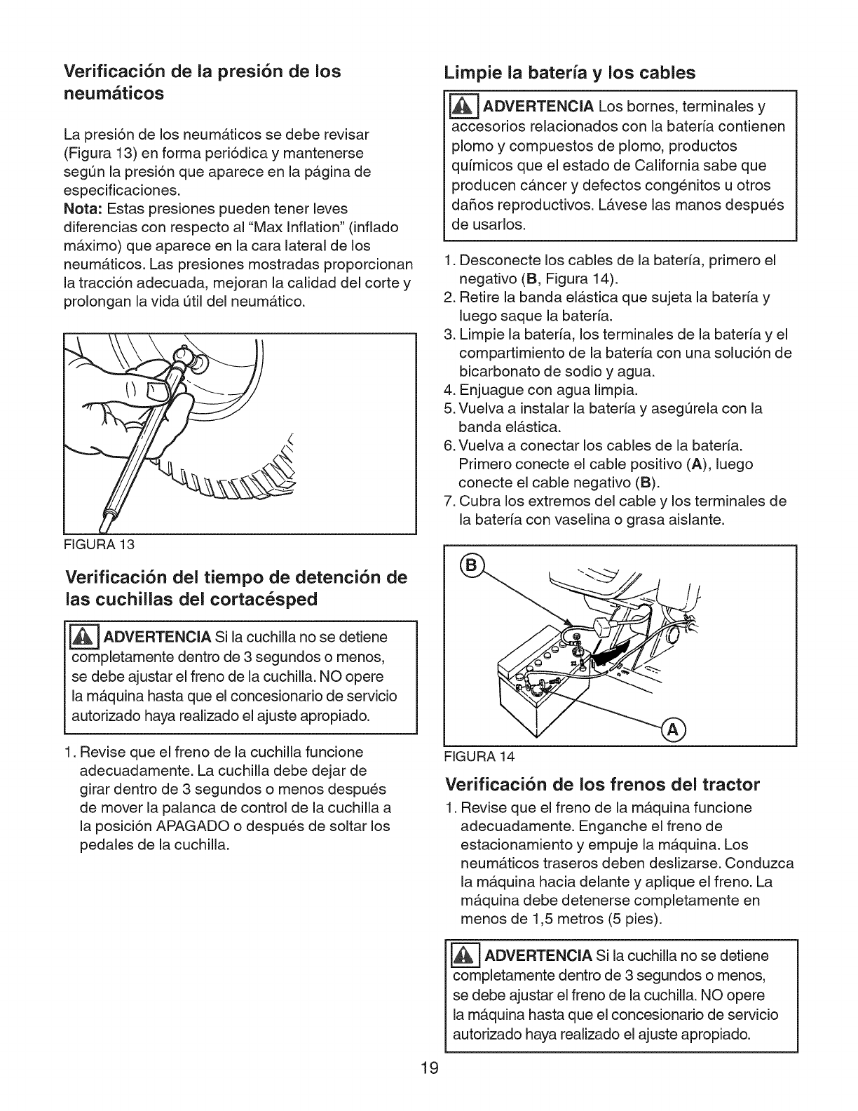
Verificaci6n de la presi6n de los
neurn_ticos
La presi6n de los neumAticos se debe revisar
(Figura 13) en forma peri6dica y mantenerse
segun la presi6n que aparece en la pagina de
especificaciones.
Nota: Estas presiones pueden tener leves
diferencias con respecto al "Max Inflation" (inflado
maximo) que aparece en la cara lateral de los
neumaticos. Las presiones mostradas proporcionan
la tracci6n adecuada, mejoran la calidad del corte y
prolongan la vida util del neumatico.
FIGURA 13
Verificaci6n del tiempo de detenci6n de
las cuchillas del cortac6sped
_ADVERTENCIA Si la cuchilla detiene
no se
completamente dentro de 3 segundos o menos,
se debe ajustar el freno de la cuchilla. NO opere
la maquina hasta que el concesionario de servicio
autorizado haya realizado el ajuste apropiado.
1. Revise que el freno de la cuchilla funcione
adecuadamente. La cuchilla debe dejar de
girar dentro de 3 segundos o menos despues
de mover la palanca de control de la cuchilla a
la posici6n APAGADO o despues de soltar los
pedales de la cuchilla.
Limpie la bateria ylos cables
_ADVERTENCIA bornes, y
Los terminales
accesorios relacionados con la bateria contienen
plomo y compuestos de plomo, productos
quimicos que el estado de California sabe que
producen cancer y defectos cong6nitos u otros
daSos reproductivos. LAvese las manos despues
de usarlos.
1. Desconecte los cables de la bateria, primero el
negativo (B, Figura 14).
2. Retire la banda elastica que sujeta la bateria y
luego saque la bateria.
3. Limpie la batefia, los terminales de la batefia y el
compartimiento de la bateria con una soluci6n de
bicarbonato de sodio y agua.
4. Enjuague con agua limpia.
5. Vuelva a instalar la bateria y asegurela con la
banda elastic&
6. Vuelva a conectar los cables de la bateria.
Primero conecte el cable positivo (A), luego
conecte el cable negativo (B).
7. Cubra los extremos del cable y los terminales de
la batefia con vaselina o grasa aislante.
FIGURA 14
Verificaci6n de los frenos del tractor
1. Revise que el freno de la maquina funcione
adecuadamente. Enganche el freno de
estacionamiento y empuje la maquina. Los
neumaticos traseros deben deslizarse. Conduzca
la maquina hacia delante y aplique el freno. La
maquina debe detenerse completamente en
menos de 1,5 metros (5 pies).
[_ ADVERTENCIA Si la cuchilla detiene
no se
completamente dentro de 3 segundos o menos,
se debe ajustar el freno de la cuchilla. NO opere
la mAquina hasta que el concesionario de servicio
autorizado haya realizado el ajuste apropiado.
19
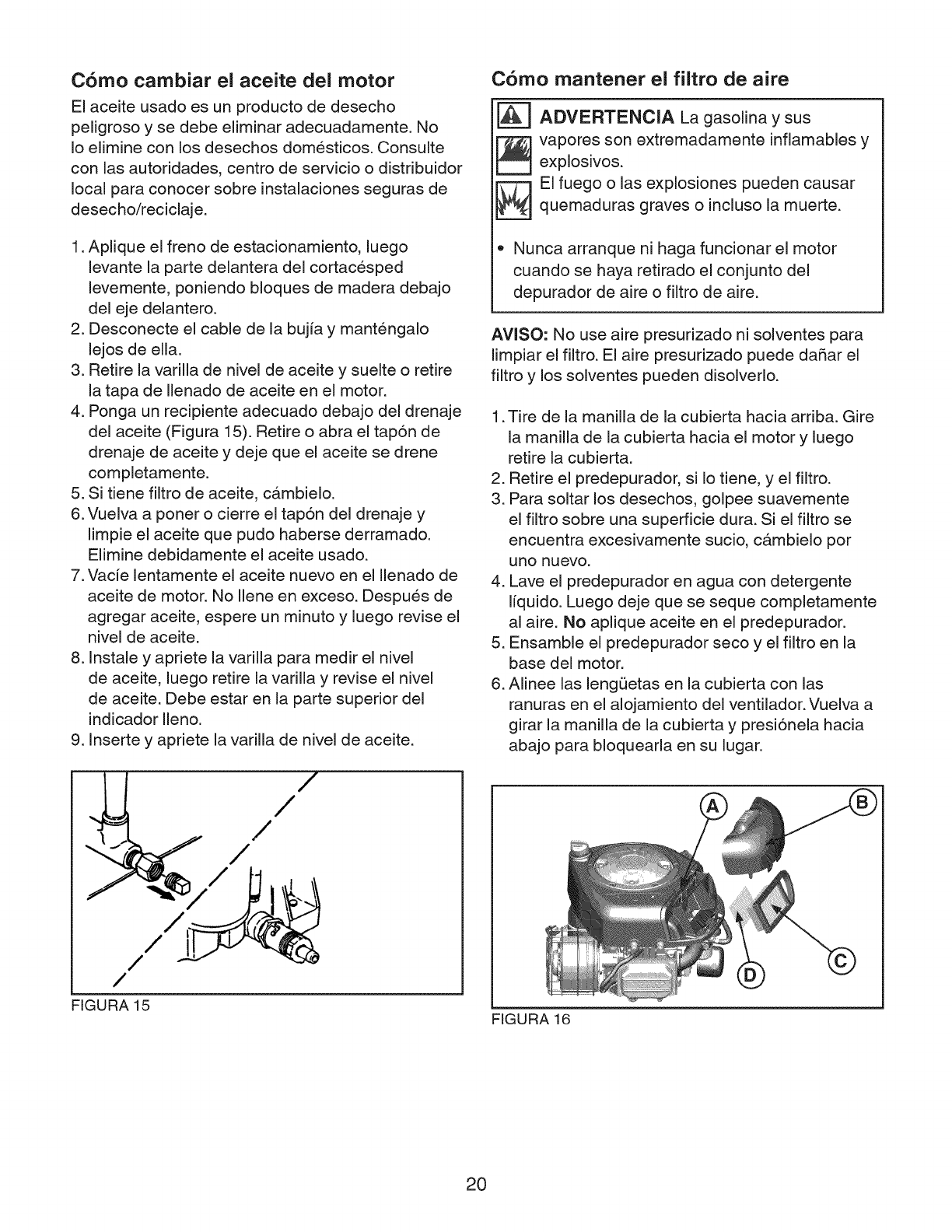
C6mo cambiar el aceite del motor
El aceite usado es un producto de desecho
peJigroso y se debe eJiminar adecuadamente. No
Io elimine con los desechos domesticos. Consulte
con las autoridades, centro de servicio o distribuidor
local para conocer sobre instalaciones seguras de
desecho/reciclaje.
1. Aplique el freno de estacionamiento, luego
levante la parte delantera del cortacesped
levemente, poniendo bloques de madera debajo
deJ eje deJantero.
2. Desconecte el cable de la bujfa y mant6ngalo
Jejos de eJJa.
3. Retire la varilla de niveJ de aceite y sueJte o retire
la tapa de Ilenado de aceite en el motor.
4. Ponga un recipiente adecuado debajo deJ drenaje
deJ aceite (Figura 15). Retire o abra el tap6n de
drenaje de aceite y deje que el aceite se drene
completamente.
5. Si tiene filtro de aceite, cambielo.
6. VueJva a poner o cierre el tap6n del drenaje y
limpie el aceite que pudo haberse derramado.
Elimine debidamente el aceite usado.
7. Vacfe Jentamente el aceite nuevo en el JJenado de
aceite de motor. No JJeneen exceso. Despu6s de
agregar aceite, espere un minuto y Juego revise el
nivel de aceite.
8. InstaJe y apriete la varilla para medir el nivel
de aceite, Juego retire JavariJJa y revise el nivel
de aceite. Debe estar en Japarte superior del
indicador Ileno.
9. Inserte y apriete la varilla de nivel de aceite.
/
/
/
/
C6mo mantener el filtro de aire
[_ ADVERTENCIA La gasolina y sus
_ apores son extremadamente infiamables y
explosivos.
EI fuego o las explosiones pueden causar
quemaduras graves o incluso la muerte.
Nunca arranque ni haga funcionar el motor
cuando se haya retirado el conjunto del
depurador de aire o filtro de aire.
AVISO: No use aire presurizado ni solventes para
limpiar eJ filtro. El aire presurizado puede dafiar eJ
filtro y los solventes pueden disolverlo.
1.Tire de la manilla de la cubierta hacia arriba. Gire
la manilla de la cubierta hacia el motor y luego
retire la cubierta.
2. Retire el predepurador, si Io tiene, y el filtro.
3. Para soltar los desechos, golpee suavemente
el filtro sobre una superficie dura. Si el filtro se
encuentra excesivamente sucio, cambielo por
uno nuevo.
4. Lave el predepurador en agua con detergente
liquido. Luego deje que se seque completamente
al aire. No aplique aceite en el predepurador.
5. Ensamble el predepurador seco y el filtro en la
base del motor.
6. Alinee las lengQetas en la cubierta con las
ranuras en el alojamiento del ventilador. Vuelva a
girar la manilla de la cubierta y presi6neia hacia
abajo para bloquearla en su lugar.
/
/
/
FIGURA 15 FIGURA 16
20
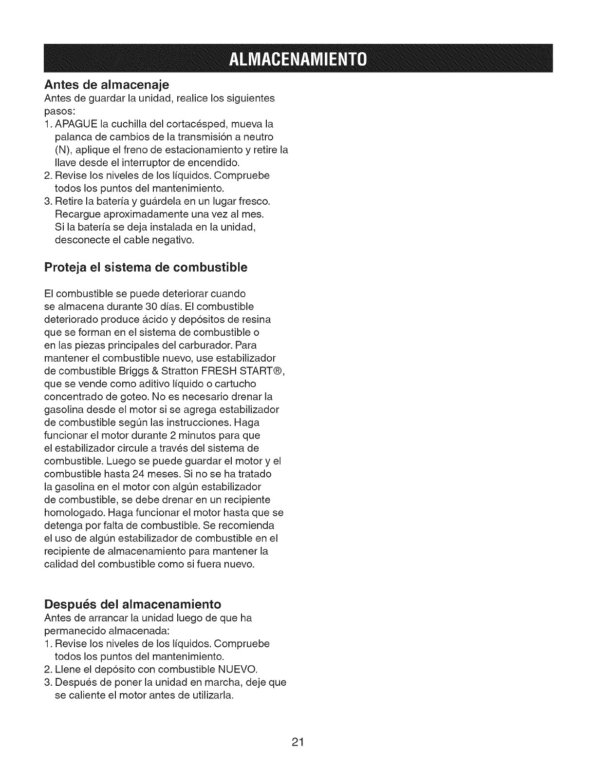
Antes de almacenaje
Antes de guardar la unidad, realice los siguientes
pasos:
1. APAGUE la cuchilla del cortacesped, mueva la
palanca de cambios de la transmisi6n a neutro
(N), aplique el freno de estacionamiento y retire la
Ilave desde el interruptor de encendido.
2. Revise los niveles de los liquidos. Compruebe
todos los puntos del mantenimiento.
3. Retire la bateria y guardela en un lugar fresco.
Recargue aproximadamente una vez al mes.
Si la bateria se deja instalada en la unidad,
desconecte el cable negativo.
Proteja el sistema de combustible
El combustible se puede deteriorar cuando
se almacena durante 30 dias. El combustible
deteriorado produce acido y dep6sitos de resina
que se forman en el sistema de combustible o
en las piezas principales del carburador. Para
mantener el combustible nuevo, use estabilizador
de combustible Briggs & Stratton FRESH START@,
que se vende como aditivo Ifquido o cartucho
concentrado de goteo. No es necesario drenar la
gasolina desde el motor si se agrega estabilizador
de combustible segQn las instrucciones. Haga
funcionar el motor durante 2 minutos para que
el estabilizador circule a traves del sistema de
combustible. Luego se puede guardar el motor y el
combustible hasta 24 meses. Si no se ha tratado
la gasolina en el motor con algQn estabilizador
de combustible, se debe drenar en un recipiente
homologado. Haga funcionar el motor hasta que se
detenga por falta de combustible. Se recomienda
el uso de algun estabilizador de combustible en el
recipiente de almacenamiento para mantener la
calidad del combustible como si fuera nuevo.
Despu_s del almacenamiento
Antes de arrancar la unidad luego de que ha
permanecido almacenada:
1. Revise los niveles de los liquidos. Compruebe
todos los puntos del mantenimiento.
2. Llene el dep6sito con combustible NUEVO.
3. Despues de poner la unidad en marcha, deje que
se caliente el motor antes de utilizarla.
21
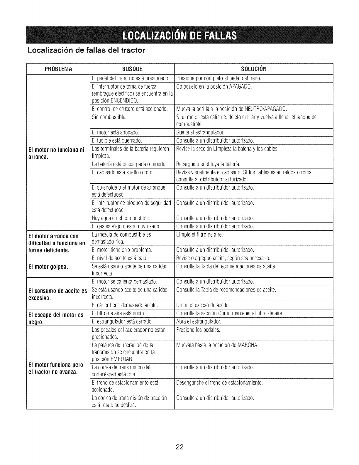
Localizaci6n de fallas del tractor
PROBLEIVIA BUSQUE SOLUCION
El pedaldelfrenonoest_presionado. Presioneporcompletoel pedaldelfreno.
El interruptordetomadefuerza ColOqueloenlaposiciOnAPAGADO.
(embragueelectrico)seencuentraenla
posiciOnENCENDIDO.
Elcontroldecruceroest_accionado. Muevala perillaa laposiciOndeNEUTRO/APAGADO.
Sincombustible. Si el motorest_caliente,dejeloenfriary vuelvaa Ilenareltanquede
combustible.
El motorest_ahogado. Suelteel estrangulador.
Elfusibleest_quemado. Consulteaundistribuidorautorizado.
El motor nofunciona ni Losterminalesdela baterfarequieren ReviselasecciOnLimpiezalabaterfay loscables.
arranca, limpieza.
Labaterfaest_descargadao muerta. Recargueo sustituyalabaterfa.
Elcableadoest_sueltoo roto. Revisevisualmenteelcableado.Si los cablesest_nrafdoso rotos,
consulteal distribuidorautorizado.
Elsolenoideo elmotordearranque Consulteaundistribuidorautorizado.
est_defectuoso.
El interruptordebloqueodeseguridad Consulteaundistribuidorautorizado.
est_defectuoso.
Hayaguaenelcombustible. Consulteaundistribuidorautorizado.
Elgasesviejoo est_muyusado. Consulteaundistribuidorautorizado.
EI motorarranca con Lamezcladecombustiblees Limpieelfiltro deaire.
dificuitado funciona en demasiadorica.
forma deficiente. El motortieneotro problema. Consulteaundistribuidorautorizado.
El niveldeaceiteest_bajo. Reviseo agregueaceite,segOnseanecesario.
El motorgolpea. Seest_usandoaceitedeunacalidad ConsultelaTabladerecomendacionesdeaceite.
incorrecta.
El motorsecalientademasiado. Consulteaundistribuidorautorizado.
El consumode aceite es Seest_usandoaceitedeunacalidad ConsultelaTabladerecomendacionesdeaceite.
excesivo, incorrecta.
Elcartertienedemasiadoaceite. Droneel excesodeaceite.
El escape dei motor es Elfiltro deaireest_sucio. ConsultelasecciOnComomantenerelfiltro deaire.
negro. Elestranguladorest_cerrado. Abraelestrangulador.
Lospedalesdelaceleradorno est_n Presionelos pedales.
presionados.
LapalancadeliberaciOndela Muevalahastala posiciOndeMARCHA.
transmisiOnseencuentraen la
posiciOnEMPUJAR.
El motor funciona pero LacorreadetransmisiOndel Oonsulteaundistribuidorautorizado.
ei tractor no avanza, cortacespedest_rota.
Elfrenodeestacionamientoest_ Desengancheel frenodeestacionamiento.
accionado.
LacorreadetransmisiOndetracciOn Consulteaundistribuidorautorizado.
est_rotao sedesliza.
22
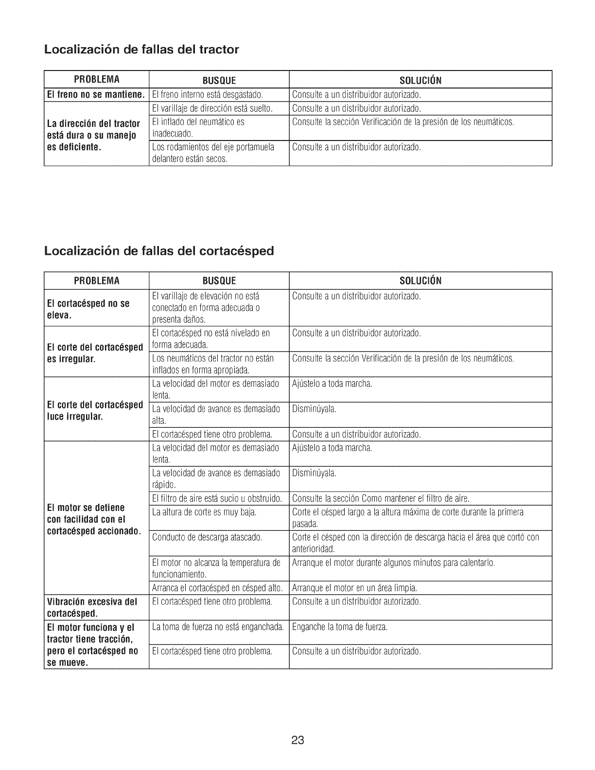
Localizaci6n de fallas del tractor
PROBLEMA BUSQUE SOLUCION
El freno nose mantiene. Elfrenointernoestadesgastado. Consulteaun distribuidorautorizado.
ElvarillajededirecciOnestasuelto. Consulteaun distribuidorautorizado.
La direcci6n del tractor El infladodelneumaticoes Consultelasecci6nVerificaci6ndelapresi6ndelos neumaticos.
est_idura o sn manejo inadecuado.
es deflciente. Los rodamientosdelejeportamuela Consulteaun distribuidorautorizado.
delanteroestansecos.
Localizaci6n de fallas del cortac_sped
PROBLElVlA BUSI::IUE SOLLICiON
ElvarillajedeelevaciOnnoesta Consulteaundistribuidorautorizado.
El cortac_spedno se conectadoenformaadecuadao
eleva, presentada_os.
Elcortacdspednoestaniveladoen Consulteaun distribuidorautorizado.
El torte del cortacesped formaadecuada.
es irregular. Los neumaticosdeltractornoestan ConsultelasecciOnVerificaciOndelapresiOndelos neumaticos.
infladosenformaapropiada.
Lavelocidaddelmotoresdemasiado AjOsteloatodamarcha.
lenta.
El eerie del cortac_sped Lavelocidaddeavanceesdemasiado DisminOyala.
lute irregular, alta.
Elcortacespedtieneotro problema. Consulteaun distribuidorautorizado.
Lavelocidaddelmotoresdemasiado AjOsteloatodamarcha.
lenta.
Lavelocidaddeavanceesdemasiado DisminOyala.
rapido.
Elfiltro deaireestasuciouobstruido. ConsultelasecciOnComomantenerelfiltro deaire.
El motor se detiene Laalturadecortees muybaja. Corteelcespedlargoa laalturamaximadecortedurantelaprimera
confaciiidad conei pasada.
cortac_spedaccionado. Conductodedescargaatascado. Corteelcespedcon la direcciOndedescargahaciael areaquecortOcon
anterioridad.
El motornoalcanzalatemperaturade Arranqueel motordurantealgunosminutosparacalentarlo.
funcionamiento.
Arrancael cortacespedencespedalto. Arranqueel motorenunarealimpia.
Vibraci6n excesiva del Elcortacespedtieneotro problema. Consulteaun distribuidorautorizado.
cortac_sped.
El motor funciona yel Latomadefuerzanoestaenganchada.Enganchelatomadefuerza.
tractor tiene tracci6n,
pero el cortacdspedno Elcortac_spedtieneotro problema. Consulteaun distribuidorautorizado.
Se rrlneve.
23
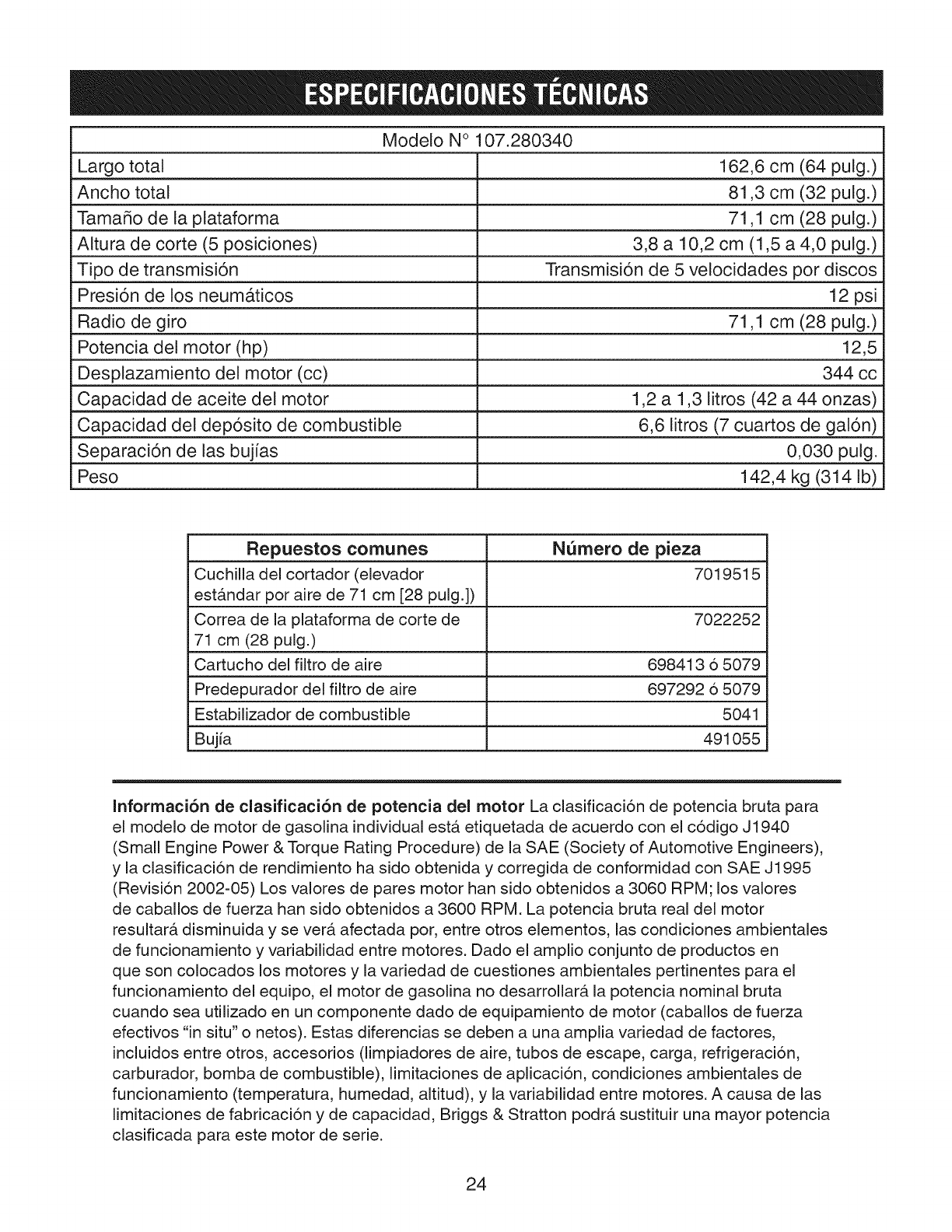
Modelo N° 107.280340
Largo total 162,6 cm (64 pulg.)
Ancho total 81,3 cm (32 pulg.)
Tama_o de la plataforma 71,1 cm (28 pulg.)
Altura de corte (5 posiciones) 3,8 a 10,2 cm (1,5 a 4,0 pulg.)
Tipo de transmisi6n Transmisi6n de 5 velocidades por discos
Presi6n de los neumaticos 12 psi
Radio de giro 71,1 cm (28 pulg.)
Potencia del motor (hp) 12,5
Desplazamiento del motor (cc) 344 cc
Capacidad de aceite del motor 1,2 a 1,3 litros (42 a 44 onzas)
Capacidad del dep6sito de combustible 6,6 litros (7 cuartos de gal6n)
Separaci6n de las bujias 0,030 pulg.
Peso 142,4 kg (314 Ib)
Repuestos comunes N_mero de pieza
Cuchilla del cortador (elevador 7019515
est&ndar por aire de 71 cm [28 pulg.])
Correa de la plataforma de corte de 7022252
71 cm (28 pulg.)
Cartucho del filtro de aire 698413 6 5079
Predepurador del filtro de aire 697292 6 5079
Estabilizador de combustible 5041
Bujia 491055
Informaci6n de clasificaci6n de potencia del motor La clasificaci6n de potencia bruta para
el modelo de motor de gasolina individual est& etiquetada de acuerdo con el codigo J1940
(Small Engine Power & Torque Rating Procedure) de la SAE (Society of Automotive Engineers),
yla clasificaci6n de rendimiento ha sido obtenida y corregida de conformidad con SAE J1995
(Revision 2002-05) Los valores de pares motor han sido obtenidos a 3060 RPM; los valores
de caballos de fuerza han sido obtenidos a 3600 RPM. La potencia bruta real del motor
resultar& disminuida y se vet& afectada pot, entre otros elementos, las condiciones ambientales
de funcionamiento y variabilidad entre motores. Dado el amplio conjunto de productos en
que son colocados los motores y la variedad de cuestiones ambientales pertinentes para el
funcionamiento del equipo, el motor de gasolina no desarrollar& la potencia nominal bruta
cuando sea utilizado en un componente dado de equipamiento de motor (caballos de fuerza
efectivos "in situ" o netos). Estas diferencias se deben a una amplia variedad de factores,
incluidos entre otros, accesorios (limpiadores de aire, tubos de escape, carga, refrigeracion,
carburador, bomba de combustible), limitaciones de aplicaci6n, condiciones ambientales de
funcionamiento (temperatura, humedad, altitud), y la variabilidad entre motores. A causa de las
limitaciones de fabricacion y de capacidad, Briggs & Stratton podr& sustituir una mayor potencia
clasificada para este motor de serie.
24

25

Your Home
For expert troubleshooting and home solutions advice:
manage home
www.managemyhome.com
For repair - in your home - of all major brand appliances,
lawn and garden equipment, or heating and cooling systems,
no matter who made it, no matter who sold it!
For the replacement parts, accessories and
owner's manuals that you need to do-it-yourself.
For Sears professional installation of home appliances
and items like garage door openers and water heaters.
1-800-4-MY-HOME ®(1-800-469-4663)
Call anytime, day or night (U.S.A. and Canada)
www.sears.com www.sears.ca
Our Home
For repair of carry-in items like vacuums, lawn equipment,
and electronics, call anytime for the location of your nearest
Sears Parts & Repair Service Center
1-800-488-1222 (U.S.A.) 1-800-469-4663 (Canada)
www.sears.corn www.sears.ca
To purchase a protection agreement on a product serviced by Sears:
1-800-827-6655 (U.S.A.) 1-800-361-6665 (Canada)
Para pedir servicio de reparaci6n Au Canada pour service en fran_ais:
a domicilio, y para ordenar piezas: 1-800-LE-FOYER Mc
1-888-S U-HOGAR ® (1-800-533-6937)
(1-888-784-6427) S__/F_ www.sears.ca
TM
® Registered Trademark /Trademark /SM Service Mark of Sears Brands, LLC
® Marca Registrada /TMMarca de Fabrica /SM Marca de Servicio de Sears Brands, LLC
MC MD
Marque de commerce /Marque depos6e de Sears Brands, LLC © Sears Brands, LLC
