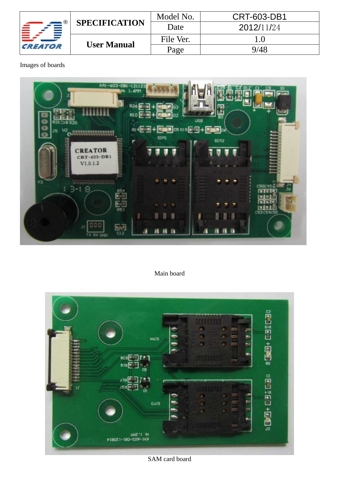
CREATOR CRT-603 Card Reader User Manual
CREATOR (CHINA) TECH CO., LTD Card Reader
UserManual.wiki
>
CREATOR
>
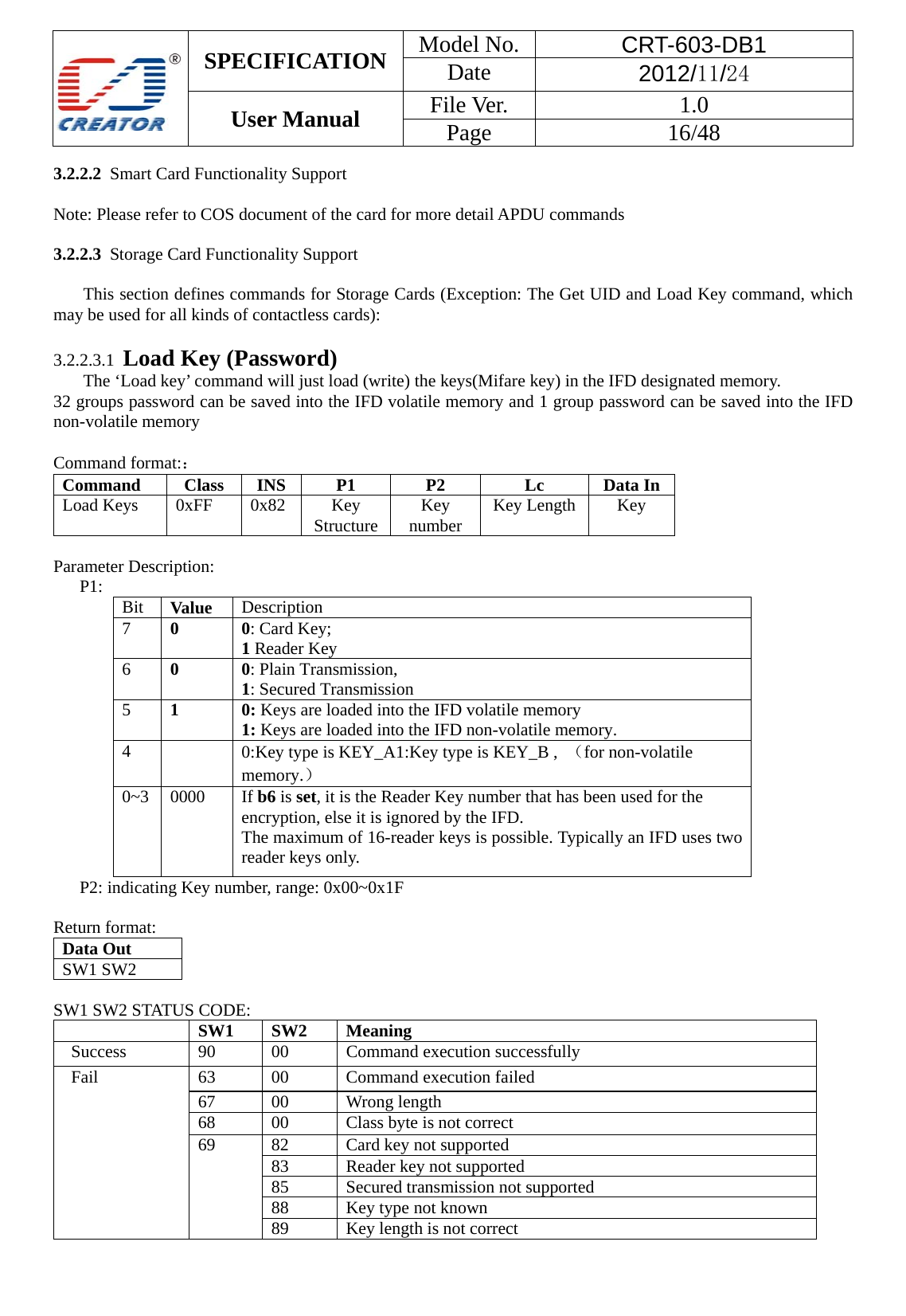
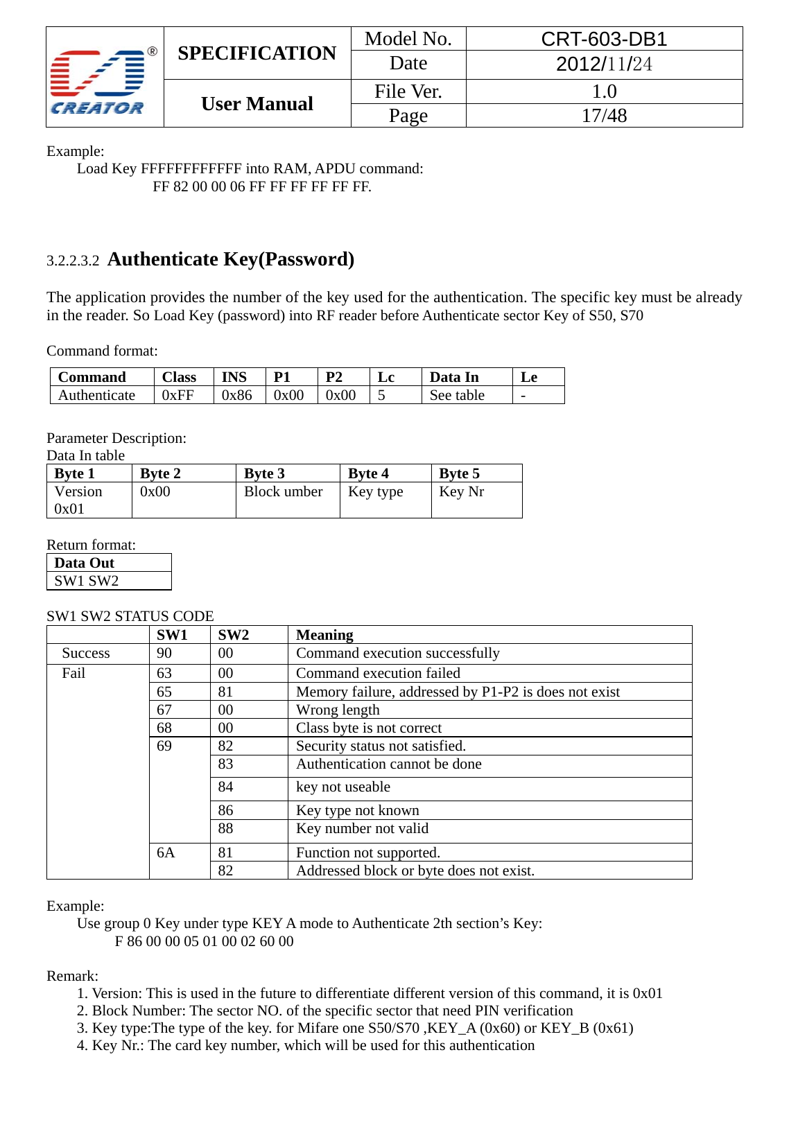
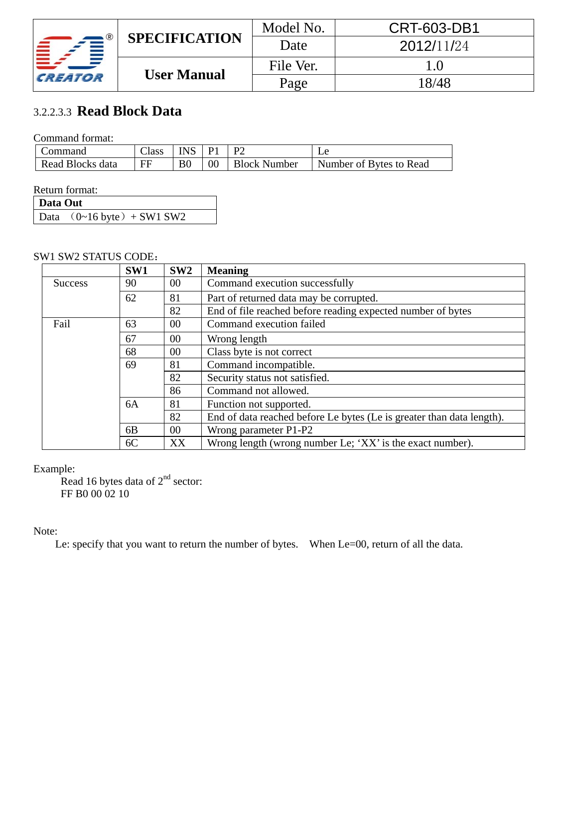
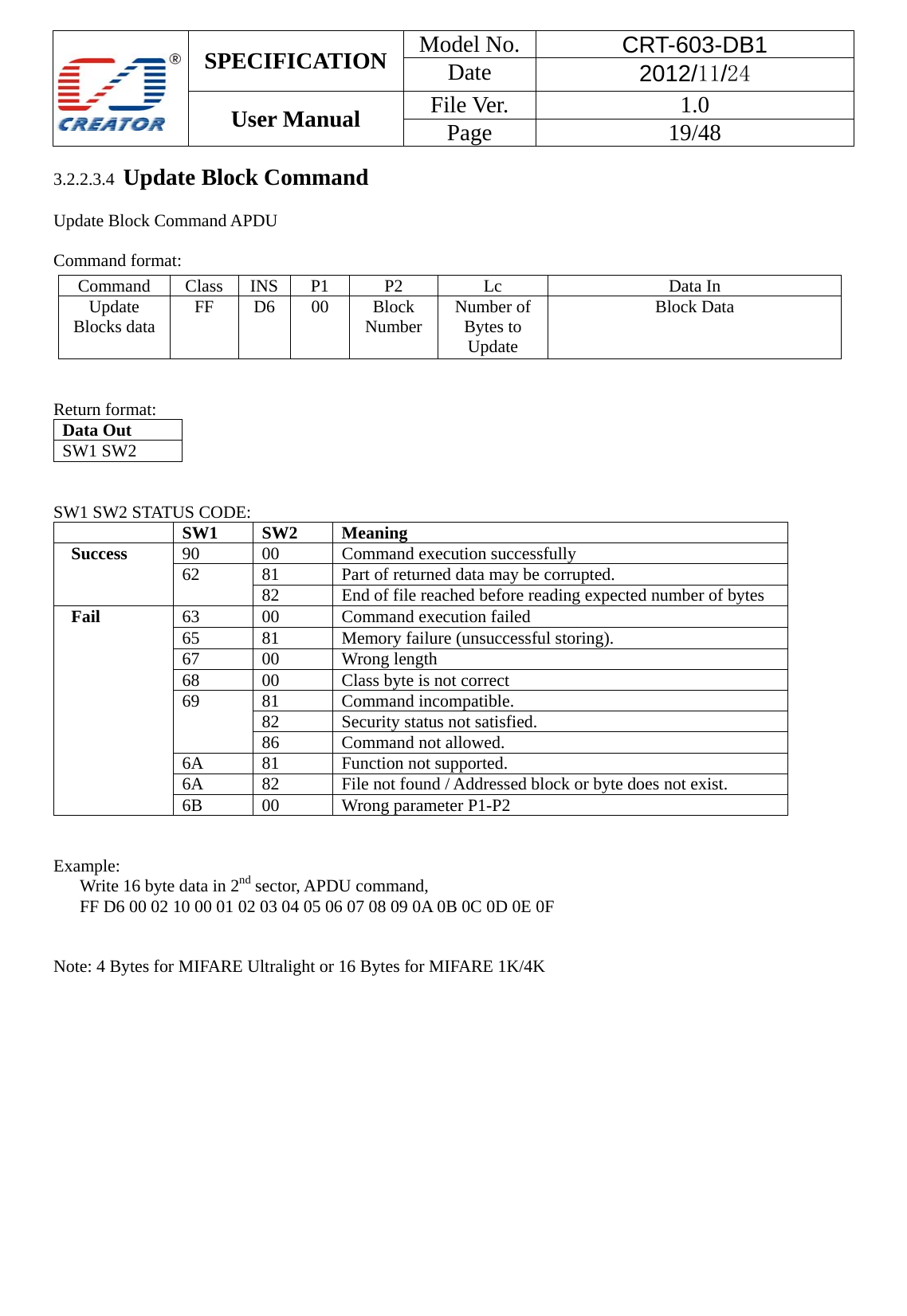
CRT 603 User Manual
User manual
Navigation menu
Upload a User Manual
Namespaces
Wiki Guide
HTML
PDF
Info
Views
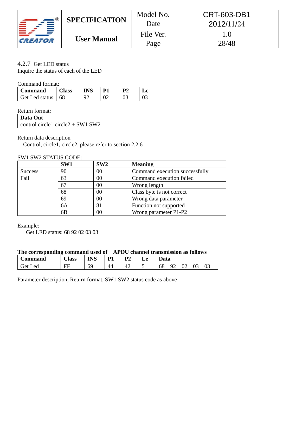
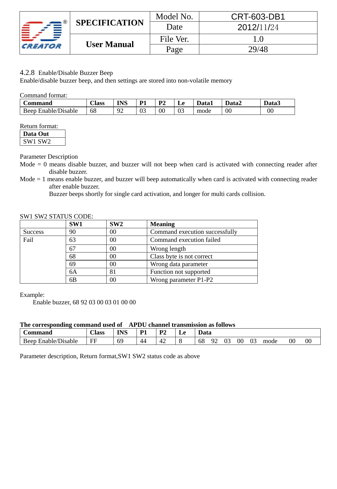
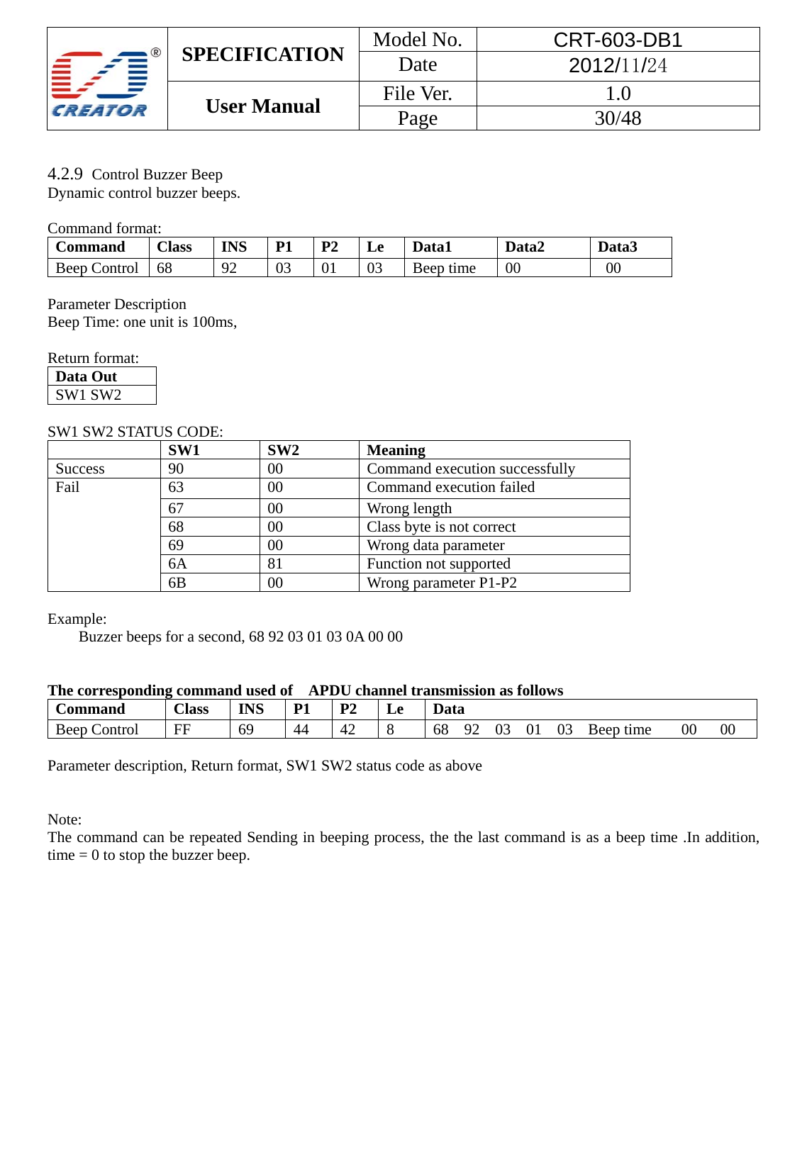
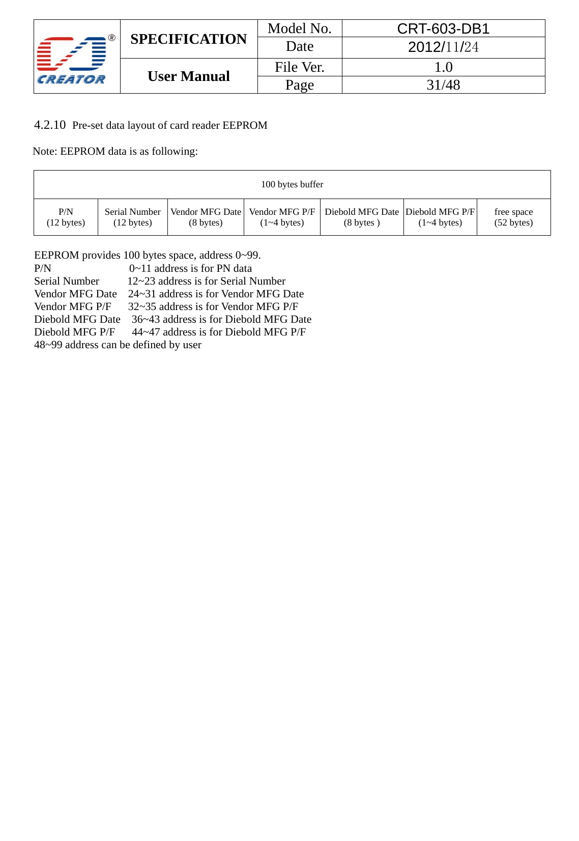
User Manual
Discussion / Help
Navigation