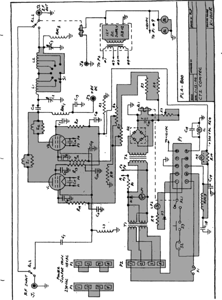
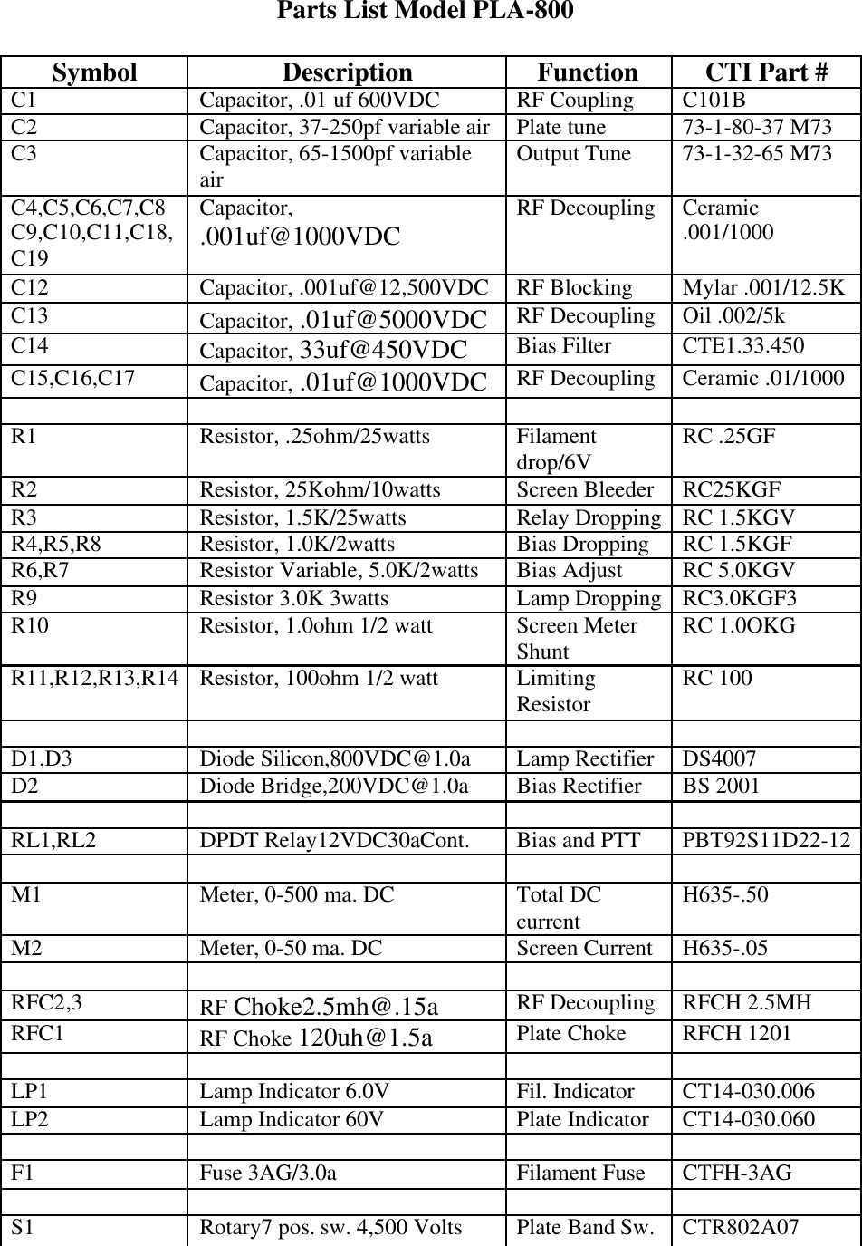
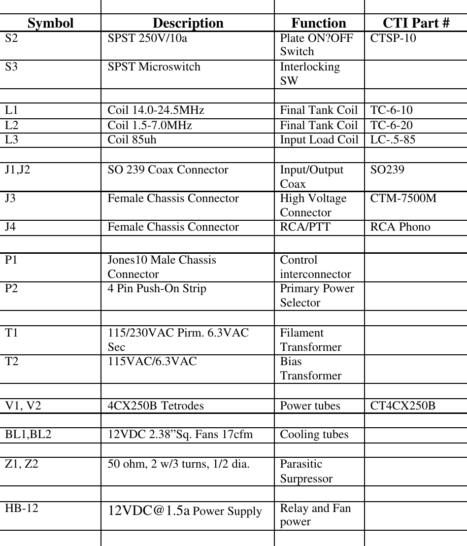
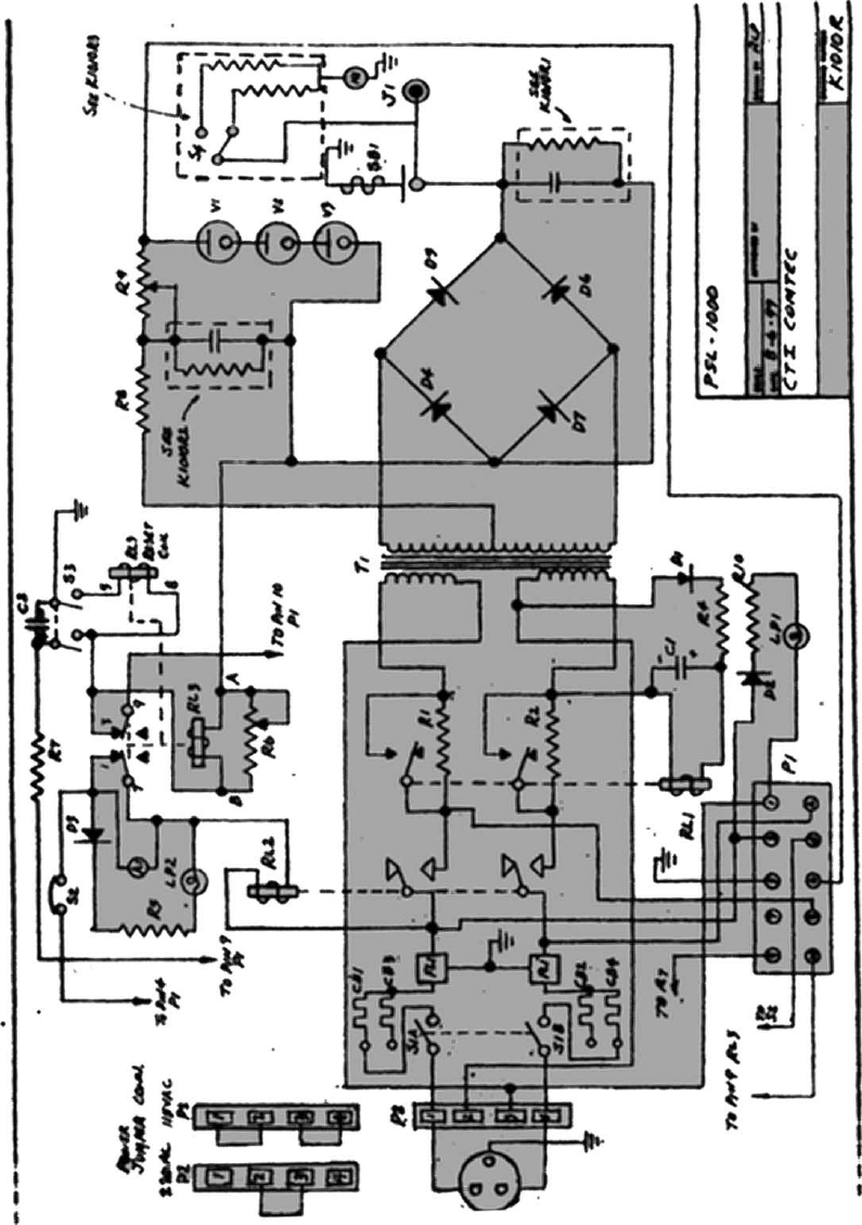
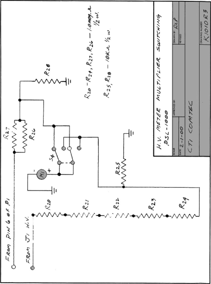
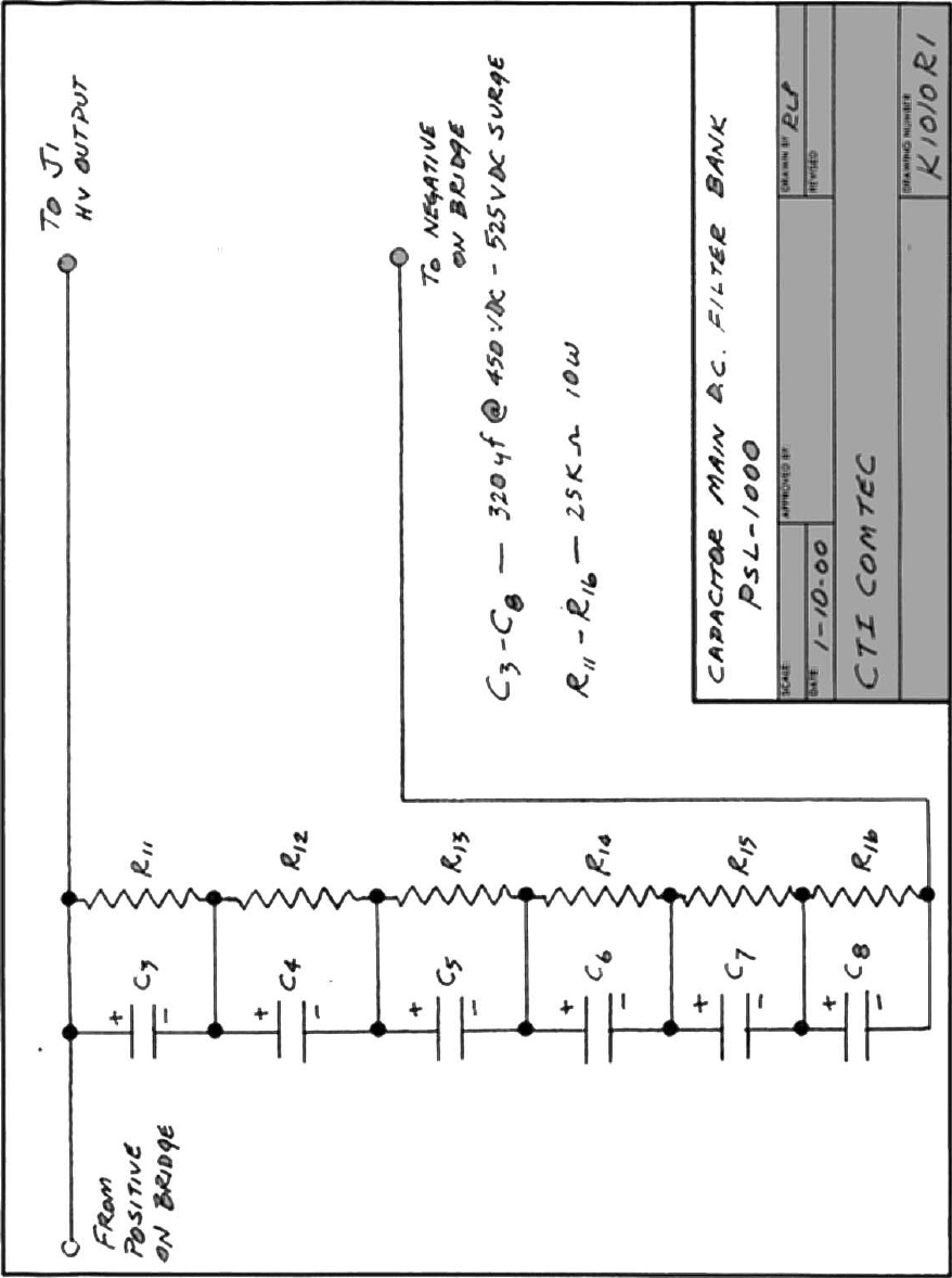
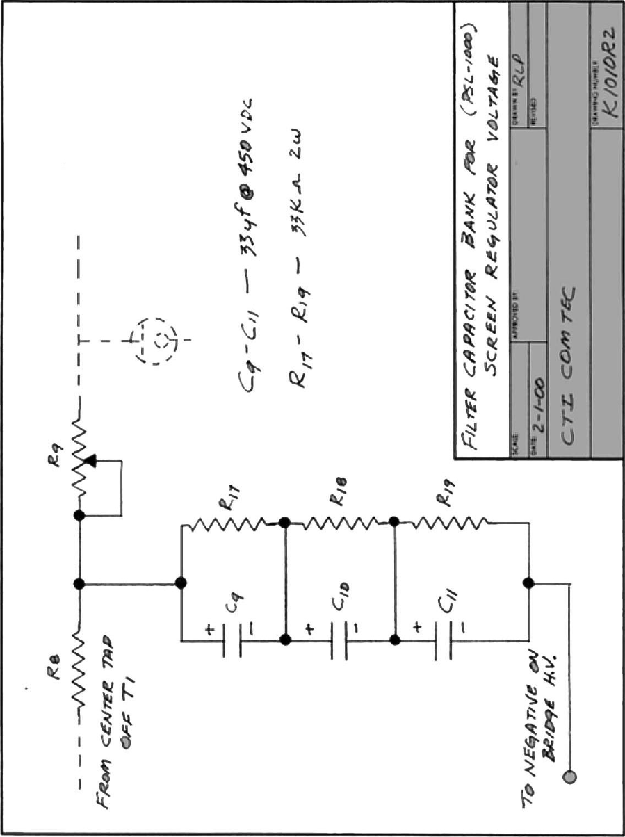
CTI ComTec PLA-800 Amplifier PLA-800 User Manual PLA800USERSMANUAL

CTI ComTec, Inc. Amplifier PLA-800 PLA800USERSMANUAL

CTIPLA

Submitted by:CTI.ComTec, Inc.1 Classic Court, NorthPalm Coast, Florida  32137386-445-5545March 16, 2002CTI.ComTec PLA-800 Power AmplifierSerial Number 1010CTI.ComTec PSL-1000 Power SupplySerial Number 1010Test Report for Grant of CertificationFor Use in Part 97 Amateur Service UnderThe Rules of the Federal Communications CommissionPLA-800 USERS MANUALAppendix C
APPENDIX CCOPY OF SETUP AND OPERATING INSTRUCTIONS
Please Read Before OperatingCaution:  Lethal High Voltage PresentBefore operating both the PLA 800 and the PSL 1000, certainprecautions should be taken.The PSL 1000 Power Supply generates over 2000 volts Direct Current ata current capacity of over.6000 amperes.  It also generates 350 VoltsDirect Current at .150 amperes.  Both voltages are Lethal and will causedeath upon contact with the human body.Although there are several built-in safety features to protect YOU fromexposure to high voltage, the following steps whould be followed at alltimes.NEVER OPERATE, EITHER THE PLA 800 OR PSL 1000, REMOVEDFROM THEIR INDIVIDUAL ENCLOSURES.NEVER REMOVE ANY CONNECTORS FROM EITHER UNITWHILE POWER IS APPLIED.NEVER INSERT METAL OBJECTS INTO THE COOLING VENTHOLES ON TOP OR BELOW EITHER UNIT, WHILE POWER ISAPPLIED.WARNINGTHE VOLTAGES USED IN THIS EQUIPMENT ARE SUFFICIENTLYHIGH TO ENDANGER LIFE.  ALL PERSONNEL ARE ADVISED TOBE THOROUGHLY FAMILIAR WITH THESE UNITS BEFORETROUBLESHOOTING THEM IN A POWER-ON CONDITION.ALWAYS USE CAUTION.
INTRODUCTIONThe PLA-800 Linear Amplifier uses a pair of 4CX250’s tetrodes as final amplifier tubes.These tubes have been used and are still used today by the military because of its compactsize and ability to put out power ina compact space.  They also have the ability to amplifysignal from .1 MHz to 500 MHz.  Therefore their power bandwidth is approximately 500MHz.The 4CX250B’s have a control screen grid.  The voltage and regulated current for thescreens are supplied by the PSL 1000 Power Supply.  Using screen voltage regulation, thegrids have the advantage of self-limiting the current flow to the plates of the tubes.  As aresult, the tubes cannot be driven into saturation causing distortion.  The maximumallowable screen current is regulated by the power supply.  Once that point of currentdemand is reached, the screen limits the plate current flow to it’s maximum.  Therefore,and ALC circuit, to prevent driver overload, is not required.The maximum plate and cathode current flow is measured by the 0-500 ma. meter on thefront panel.  The screen current only, is measured by the 0-50 ma. meter located also on thefront panel.The band switch and plate and loading capacitors are also located on the front panel.  Thecapacitors use a 6:1 vernier ball drive to give smooth, easy tuning.  Also located on thefront panel are the two lights indicating filament voltage on and plate current on.  Thefilament supply is contained in the PLA-800 and is protected by the 3 AG fuse next to theindicator light.  These bulbs are tungsten elements, with a life of 50,000 hours.  The plateon and off switch is located in the middle of both lamps.Both the amplifier and power supply are inter-locked for your safety.  The removal of theFOUR (4) thumbscrews will allow you to slide the units forward and out of their respectiveenclosures.  NEVER open either unit with the AC and DC power applied.  As an addedsafety feature, the power supply has a mechanical shorting rod, which, upon sliding theunit out of the enclosure beyond 1/4 of an inch, will ground the high voltage capacitorbank.  This is done for your safety and should NOT be defeated.Built into the PSL 1000 power supply is a maximum current overload circuit.  If more than600 ma. is delivered to the load, the circuit will activate, opening the plate relay andremoving the high voltage.  At the same time, the current overload indicator lamp on thefront panel of the power supply will light and an audible alarm will sound.  To reset thehigh voltage back, simply push the reset button on the panel.  The power supply is alsoequipped with a voltmeter allowing you to monitor the high voltage (0-500 vdc) and thescreen voltage (0-500 vdc).Under normal loading conditions, the PLA-800 will deliver 600 watts key down or 1200watts PEP output.  However, the key down power level should not be maintained for morethan 10 seconds.  In cases where RTTY or AM is used, the amplifier should be operated atone-half power level.  1200 watts PEP can be operated at any time.
Tuning ProcedureOn the rear panel of the PLA-800 you will see the Power Output Connector or RF Out(SO239), a High Voltage connector, a Control Voltage Connector, a Push-to-Talk jack, aGround Connector, and the Power Input Connector (SO239) or RF In.Connect the Control Voltage Connector and High Voltage Connector between theamplifier and power supply.  The power supply has the appropriate mating connectorsalong with the AC input power plug.  The AC input power can be adapted to 115 VAC or230 VAC service (See power change over section).Apply the RF in coax connector from your transceiver.  A transceiver with a variableoutput control should be used.  That is, one which can vary the amount of drive power tothe amplifier.  Set your drive control on the transceiver to minimum.  Connect the PTT(push-to-talk) connection using the RCA jack to your transceiver.  This will put theamplifier into the circuit when you transmit from your transceiver.  In the receive mode,the amplifier will be in by-pass.Connect a coax line from the RF OUT to your tuner or directly into your antenna load.  Anoutput power watt meter should be used, in-line with the antenna.  This should be used totune the amplifier correctly.Upon completion of the above, double check all connections to make sure they areinstalled correctly and tightly.Apply AC power by switching on the Main Power Switch on the power supply front panel.The green indicator light will illuminate and the yellow filament light on the amplifier willilluminate.  Be certain that the plate switch on the amplifier is OFF.  You will hear the fansin the amplifier also begin to operate.  Let the amplifier warm up for approximately 60seconds.  This will ensure that the filaments of the 4CX250Bs will come up to temperature.After 60 seconds of warm up, turn on the plate switch located on the front panel of theamplifier.  Observe the meter readings on the amplifier.  The plate meter should come offof the Zero position by about 10 ma. and the screen current meter should read 0 ma.  Theseare the resting currents for both circuits without drive applied.Select the desired band for both amplifier and driver.  Simply turn the band switch on theamplifier to the desired band.  Place the driver (transceiver) in the CW mode.  If you havea transceiver with an Auto Tune Control, press the auto-tune function.With the key down on the transceiver, begin to increase the drive control on the transceiverand bring the plate current on the amplifier to approximately 300 ma.  Begin tuning theplate turning control and the loading control fir a maximum reading on the power wattmeter.  If you have a tuner with an SWR meter in the circuit, be sure to tune the SWR forminimum.  Remember, the maximum output with minimum SWR.  Continue to tune at thispower level until you are confident that the amplifier is adjusted properly.  It is possible totune the amplifier too heavily.  Continue to adjust the output for maximum by alternating
between the Plate Tuning and Loading Controls.  Do NOT exceed the 300 ma. current onthe plate meter in CW.DO NOT DRIVE AT THIS CURRENT LEVEL FOR MORE THAN 10 SECONDS AT ATIME.  Release the carrier for 10 seconds and then key down again to optimize output.Once at maximum output, remove the drive and let the amplifier cool down for about 10seconds.  Increase the drive level on your exciter to show a 500 ma. reading on the PlateMeter.  Screen Current should be at 30 ma.  If the screen current is showing a negativedownturn on the meter, the plate loading is too heavy.  Simply back off the loading controluntil the screen current reads 30 ma.  Tetrodes do exhibit negative screen current.  This isOK.  Depending upon the load value, it is possible to show negative screen current withmaximum output.  You should be at the maximum output of the amplifier.If there is excessive drive and plate current, the overload circuit will activate.  Reset it bypushing in on the reset button on the Power Supply.At this point you should be ready to transmit SSB or CW.  Place your driver into SSB andmodulate normally.  You will see the Plate Meter kick up to 500 ma. and the output willexceed 1200 watts PEP.  If RTTY is used, you must reduce the plate current to 250 ma. asa maximum operating plate current.Bias AdjustmentOn the rear panel of the PLA-800 is a RED square push button and an ORANGE coloredtest point jack.  To adjust the bias on the 4CX250Bs follow the steps below.1. Remove the high voltage RED connector to the amplifier on the rear panel.2. Place the PLATE SWITCH on the front panel to OFF.3. Place a multimeter in DC Volts position and on a scale of 0-2—volts.  Insert thenegative lead of the multimeter into the orange test point jack.  Ground thepositive lead of the multimeter to chassis ground on the amplifier.4. Turn the PSL 1000 Main Power Switch to ON.5. Push in on the RED square button switch and read the bias voltage on themultimeter.6. To adjust the bias voltage, use a straight blade screwdriver in the pot control onthe rear of the amplifier, next to the test point jack.7. You must continue to push in on the red switch to adjust the bias.8. The correct voltage for the 4CX250Bs is –57 volts DC.9. Once adjusted, release the red button switch and the bias voltage will climb tothe cutoff voltage which will be above –100 Volts DC.10. The bias is now adjusted for AB1 service and the amplifier can be operated.Power Change OverBoth the PLA-800 and PSL 1000 can be used for 115 volt C/50-60 Hz operation or 230volts AC/50-60 Hz operation.  The units are supplied for 115 VAC operation unlessspecifically requested.
Change over to 230 VAC is simple.1. Remove the PLA-800 from it’s enclosure by removing the four (4)thumbscrews on the front panel and slide the unit out by pulling on the frontgrab handle.2. Turn the PLA-800 over exposing the underneath chassis compartment.  In thelower right rear, from the front panel end, there is a four (4) pin terminal blockwith push on connectors.  You can count the pins on the block from 1 (one)through 4 (four) in either direction.  There are two black jumpers connectingpins 1, 2, 3, and 4.  Remove the two jumpers from their respective pins bygrabbing the insulated portion of the connector pins.3. Replace ONE jumper back onto the terminal block, by pushing each end of thejumper onto pins 2 and 3.This completes the change over of the PLA-800 to 230 VAC.For the PSL 1000 Power Supply change over follow these steps.1. Remove the PSL 1000 from it’s enclosure in the same way as the PLA-800.Turn the power supply over, exposing the underneath chassis.2. At the bottom left rear of the chassis is the same type four (4) pin terminalblock as in the PLA-800.  Remove the two (2) jumpers and replace one (1)jumper to pins 2 and 3.3. Find the push on the terminal connected to chassis ground (green wire withpush-on terminal).  Connect it to terminal 2 as well.  (The same procedure wasused with the PLA-800 with the exception of the ground push-on connector.)4. Next, you will change over pins located in the front underneath portion of thepower supply.  You will see four (4) breaker overloads.  Two (2) for 115 VoltAC (10 AMP) and two (2) for 230 Volt AC (5 AMP).  Pull the WHITE WIREconnector from the 10 AMP Breaker and push it onto the 5 AMP Breaker.  Dothe same for the BLACK WIRE connector.  Make sure that the white wire isattached to the breaker with the white wire already attached on the breaker.The same for the black wire to the breaker with the black wire already attached.This completes the internal change over for both the PLA-800 and the PSL1000.  Return the units back to their respective enclosures and replace the four(4) thumbscrews securely.5. Finally, replace the male connector on the line cord with an appropriate 230VAC plug.  Since there are many types of connectors for primary power, it isrecommended that you consult your local electrician or if you are familiar withan existing plug arrangement already in operation, use the plug required.  Makesure that the GREEN wire in the line cord, normally used for ground at 115VAC operation, now becomes the neutral for 230 VAC operation.
Parts List Model PLA-800SymbolDescriptionFunctionCTI Part #C1Capacitor, .01 uf 600VDCRF CouplingC101BC2Capacitor, 37-250pf variable airPlate tune73-1-80-37 M73C3Capacitor, 65-1500pf variableairOutput Tune73-1-32-65 M73C4,C5,C6,C7,C8C9,C10,C11,C18,C19Capacitor,.001uf@1000VDCRF DecouplingCeramic.001/1000C12Capacitor, .001uf@12,500VDCRF BlockingMylar .001/12.5KC13Capacitor, .01uf@5000VDCRF DecouplingOil .002/5kC14Capacitor, 33uf@450VDCBias FilterCTE1.33.450C15,C16,C17Capacitor, .01uf@1000VDCRF DecouplingCeramic .01/1000R1Resistor, .25ohm/25wattsFilamentdrop/6VRC .25GFR2Resistor, 25Kohm/10wattsScreen BleederRC25KGFR3Resistor, 1.5K/25wattsRelay DroppingRC 1.5KGVR4,R5,R8Resistor, 1.0K/2wattsBias DroppingRC 1.5KGFR6,R7Resistor Variable, 5.0K/2wattsBias AdjustRC 5.0KGVR9Resistor 3.0K 3wattsLamp DroppingRC3.0KGF3R10Resistor, 1.0ohm 1/2 wattScreen MeterShuntRC 1.0OKGR11,R12,R13,R14Resistor, 100ohm 1/2 wattLimitingResistorRC 100D1,D3Diode Silicon,800VDC@1.0aLamp RectifierDS4007D2Diode Bridge,200VDC@1.0aBias RectifierBS 2001RL1,RL2DPDT Relay12VDC30aCont.Bias and PTTPBT92S11D22-12M1Meter, 0-500 ma. DCTotal DCcurrentH635-.50M2Meter, 0-50 ma. DCScreen CurrentH635-.05RFC2,3RF Choke2.5mh@.15aRF DecouplingRFCH 2.5MHRFC1RF Choke 120uh@1.5aPlate ChokeRFCH 1201LP1Lamp Indicator 6.0VFil. IndicatorCT14-030.006LP2Lamp Indicator 60VPlate IndicatorCT14-030.060F1Fuse 3AG/3.0aFilament FuseCTFH-3AGS1Rotary7 pos. sw. 4,500 VoltsPlate Band Sw.CTR802A07
SymbolDescriptionFunctionCTI Part #S2SPST 250V/10aPlate ON?OFFSwitchCTSP-10S3SPST MicroswitchInterlockingSWL1Coil 14.0-24.5MHzFinal Tank CoilTC-6-10L2Coil 1.5-7.0MHzFinal Tank CoilTC-6-20L3Coil 85uhInput Load CoilLC-.5-85J1,J2SO 239 Coax ConnectorInput/OutputCoaxSO239J3Female Chassis ConnectorHigh VoltageConnectorCTM-7500MJ4Female Chassis ConnectorRCA/PTTRCA PhonoP1Jones10 Male ChassisConnectorControlinterconnectorP24 Pin Push-On StripPrimary PowerSelectorT1115/230VAC Pirm. 6.3VACSecFilamentTransformerT2115VAC/6.3VACBiasTransformerV1, V24CX250B TetrodesPower tubesCT4CX250BBL1,BL212VDC 2.38”Sq. Fans 17cfmCooling tubesZ1, Z250 ohm, 2 w/3 turns, 1/2 dia.ParasiticSurpressorHB-1212VDC@1.5a Power SupplyRelay and Fanpower
CTI.ComTec, hereinafter referred to as CTI, warrants the equipment (except electrontubes, fuses, lamps, batteries and articles made of glass or other fragile or other expendablematerials) purchased hereunder to be free from defect in materials and workmanship undernormal use and service, when used for the purposes for which the same is designed, for aperiod of one year from the date of delivery F.O.B. factory.  CTI further warrants that theequipment will perform in a manner equal to or better than the published technicalspecifications as amended by any additions or corrections thereto accompanying the formalequipment offer.CTI will replace or repair any such defective items, F.O.B. factory, which may fail withinthe stated warranty period, PROVIDED;1. That any claim of defect under this warranty is made within sixty (60) daysafter discovery thereof and that inspection by CTI, if required, indicates thevalidity of such claim to CTI’s satisfaction.2. That the defect is not the result of damage incurred in shipment from or to thefactory.3. That the equipment has not been altered in any way either as to design or usewhether by replacement parts not supplied or approved by CTI, or otherwise.4. That any equipment or accessories furnished but not manufactured by CTI, ornot of CTI design shall be subject only to such adjustments as CTI may obtainfrom the supplier thereof.Electron tubes* furnished by CTI, but manufactured by others, bear only the warrantygiven by such other manufacturers.  Electron tube wsarranty claims should be madedirectly to the manufacturer of such tubes.CTI’s obligation under this warranty is limited to the repair or replacement of defectiveparts with the exception noted above.At CTI’s option, any defective part or equipment which fails within the warranty period,shall be returned to CTI’s factory for inspection, properly packed with shipping chargesprepaid.  No parts or equipment shall be returned toCTI, unless a return authorization isissued by CTI.  If, for any reason, any equipment is returned for a full refund, there will bea 20% restocking charge deducted from the selling price.No warranties, express or implied, other than those specifically set forth herein shall beapplicable to any equipment manufactured or furnished by CTI and the foregoing warrantyshall constitute the Buyers sole right and remedy.  In no event does CTI assume anyliability for consequential damages, or for loss, damage or expense directly or indirectlyarising from the use of CTI products, or any inability to use them either separately or incombination with other equipment or materials or from any other cause.*Electron tubes also includes semi-conductor devices
PROCEDURE FOR RETURN OF MATERIAL OR EQUIPMENTShould it be necessary to return equipment or material for repair or replacement, whetherwithin warranty or otherwise, a return authorization must be obtained from CTI prior toshipment.  The request for return authorization should include the following instructions:1. Model Number of Equipment2. Serial Number of Equipment3. CTI Part Number4. Nature of defect or cause of failure5. The contact or purchase order under which equipment was deliveredPROCEDURE FOR ORDERING REPLACEMENT PARTSWhen ordering replacement parts, the following information must be included in the orderas applicable:1. Quantity required2. CTI Part Number3. The Equipment Model Number in which part(s) are used4. Brief Description of the ItemPROCEDURE IN THE EVENT OF DAMAGE INCURRED INSHIPMENTCTI’s Warranty specifically excludes damage incurred in shipment to or from the factory.In the event equipment is received in damaged condition, the carrier should be notifiedimmediately.  Claims for such damage should be filed with the carrier involved and notCTI.All correspondence pertaining to Warranty Claims, return, repair, or replacement and allmaterial or equipment returned for repair or replacement, within Warranty or otherwise,should be addressed as follows:CTI.ComTec, Inc.Engineering Services Department1 Classic Court NorthPalm Coast, FL  32137

Navigation menu