Cadi Scientific SMB800 SmartBRIDGE User Manual SMB 800 instructions for use
Cadi Scientific Pte. Ltd. SmartBRIDGE SMB 800 instructions for use
UserManual.wiki
>
Cadi Scientific
>
SMB800 User Manual
>
manual
Contents
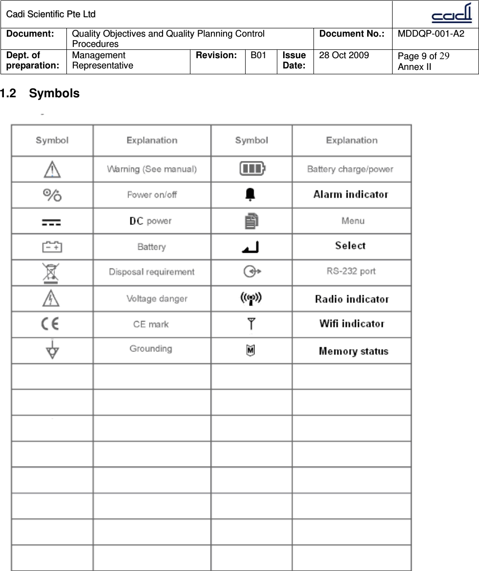
1.
manual
2.
manual2
3.
manual1
manual
Navigation menu
Upload a User Manual
Namespaces
Wiki Guide
HTML
PDF
Info
Views
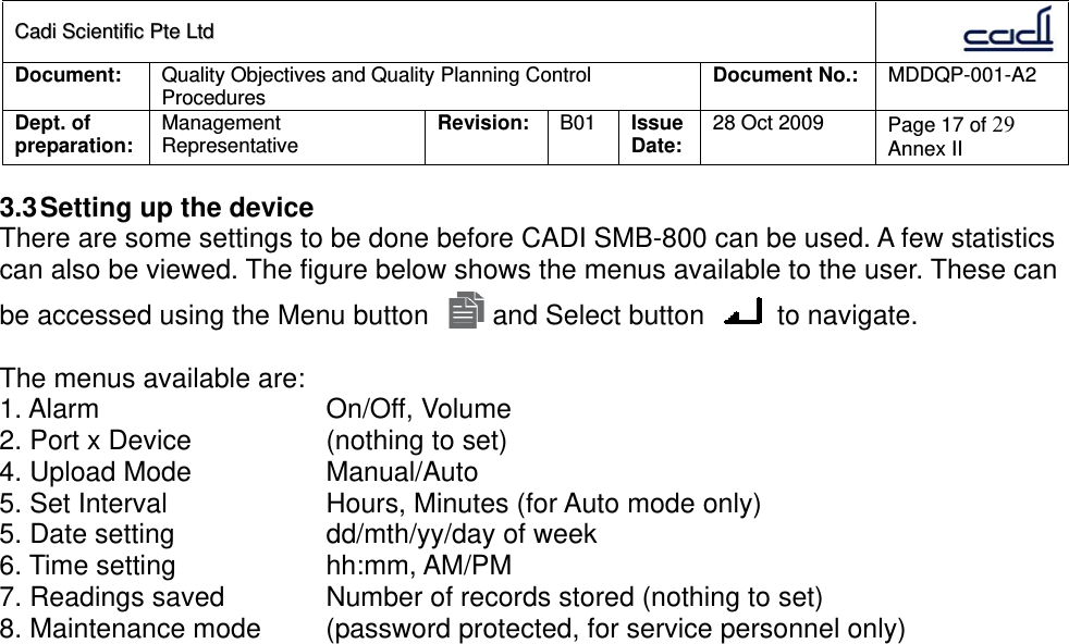
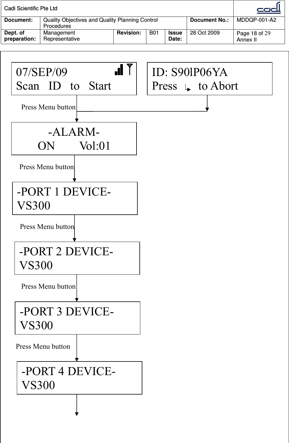
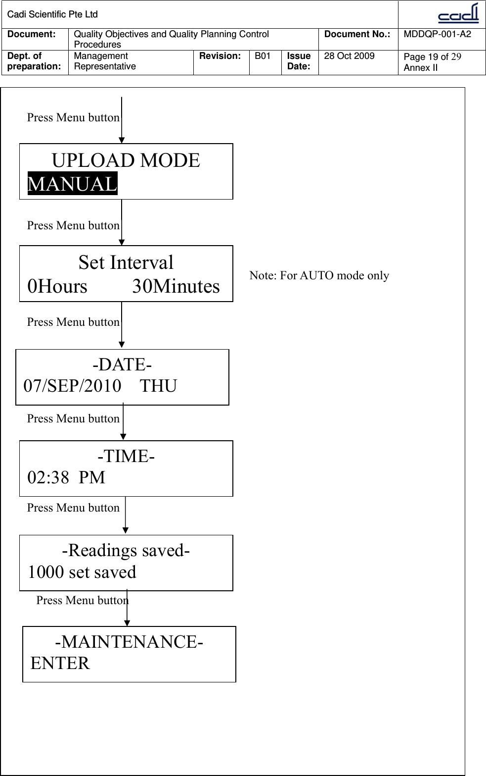
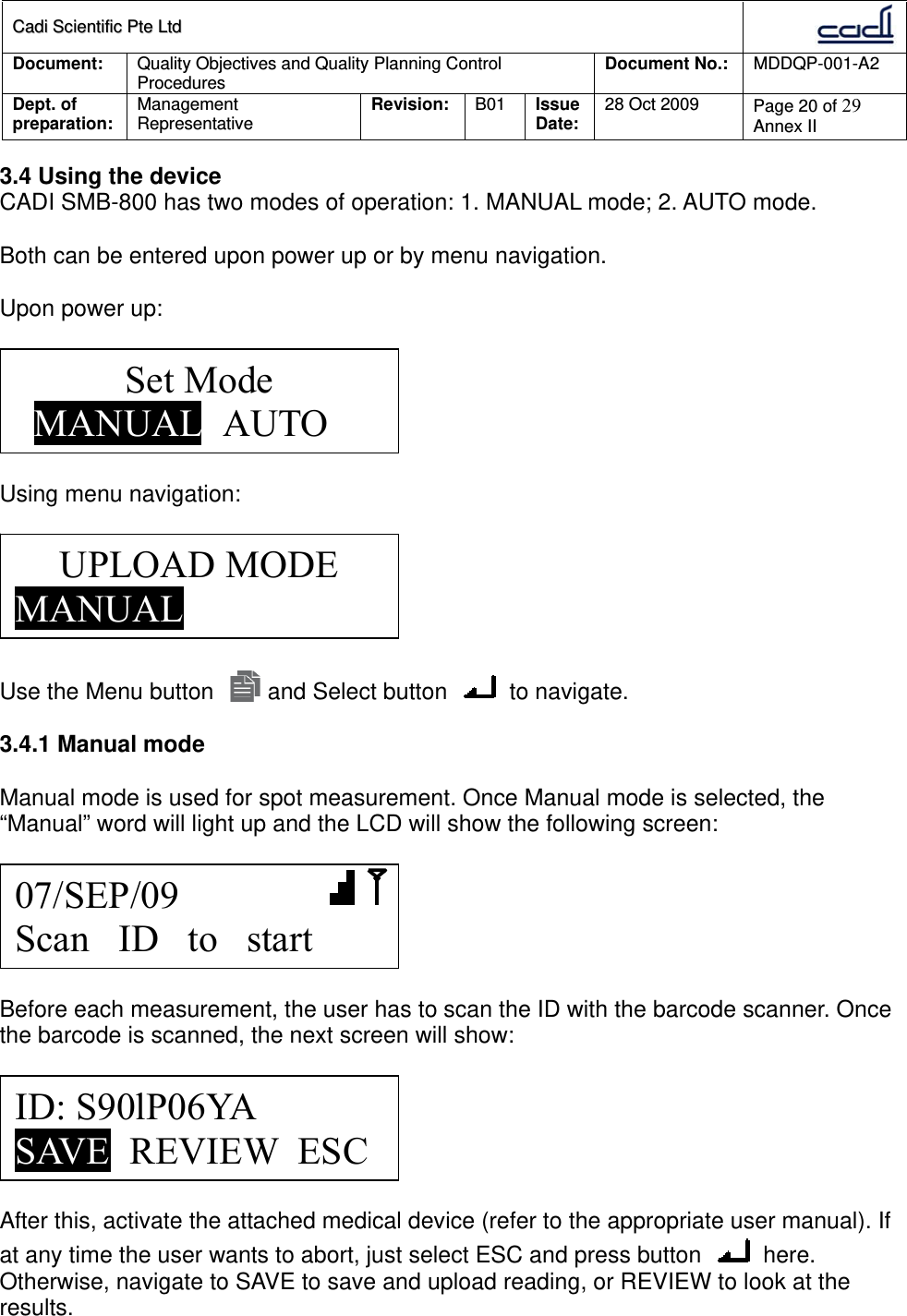
User Manual
Discussion / Help
Navigation