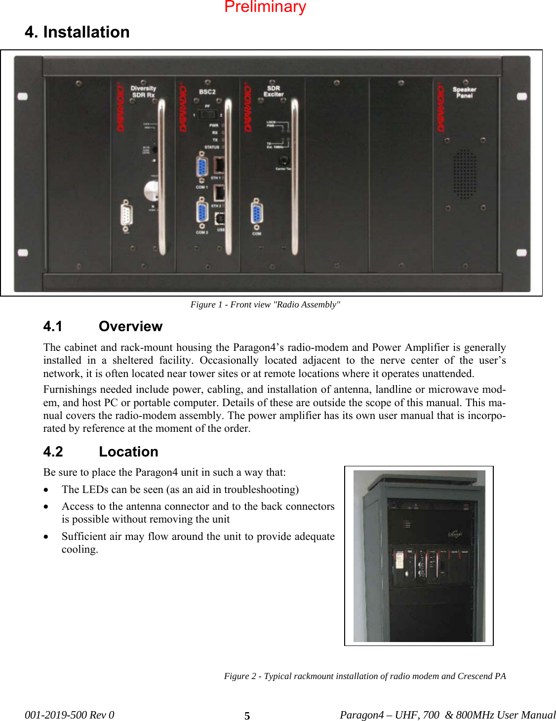
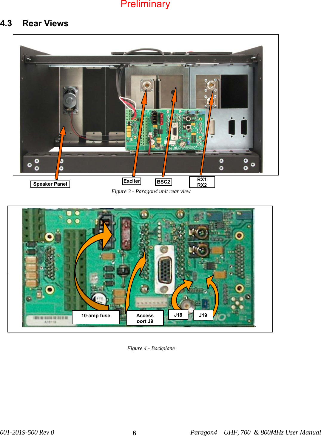
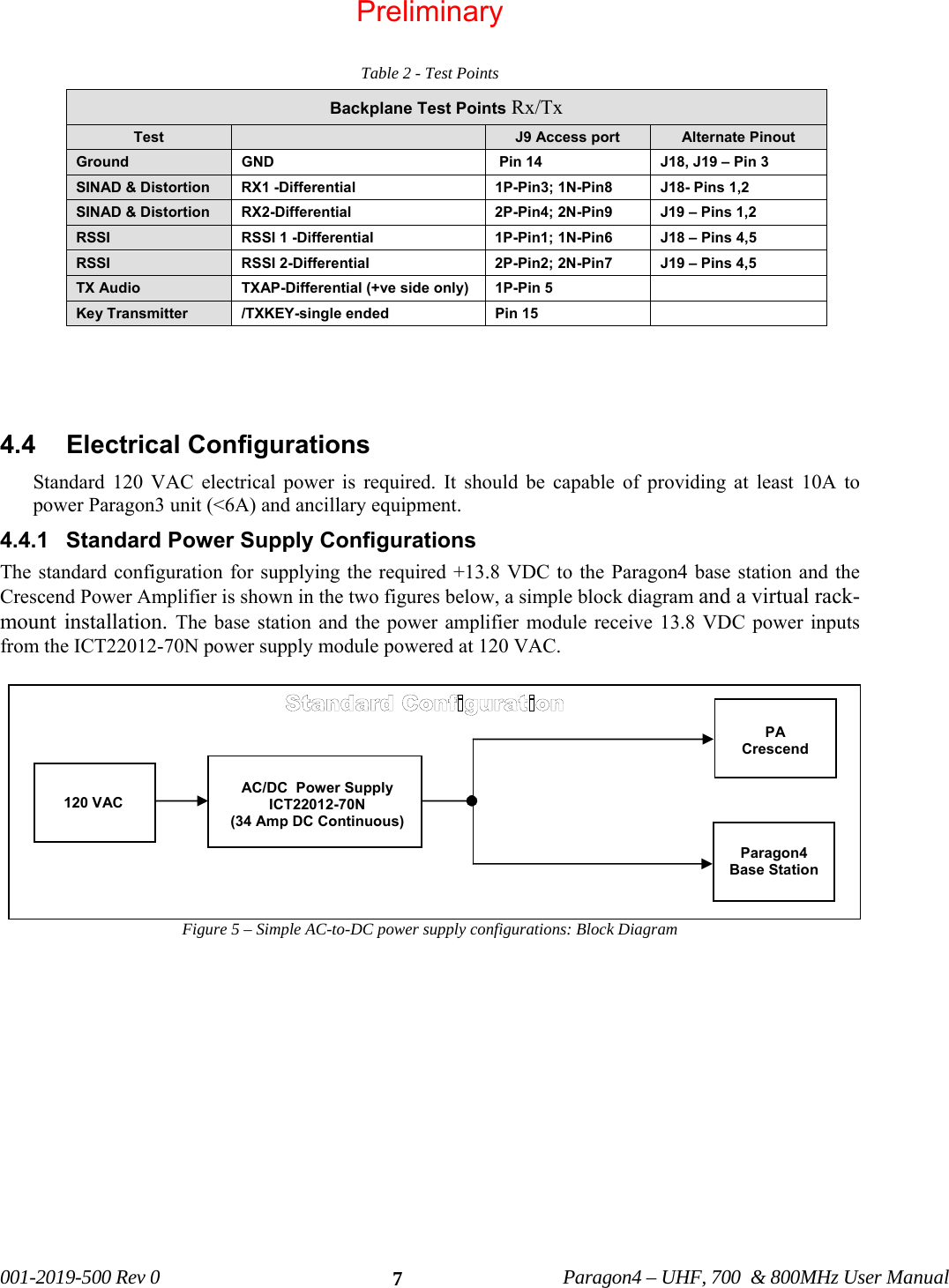
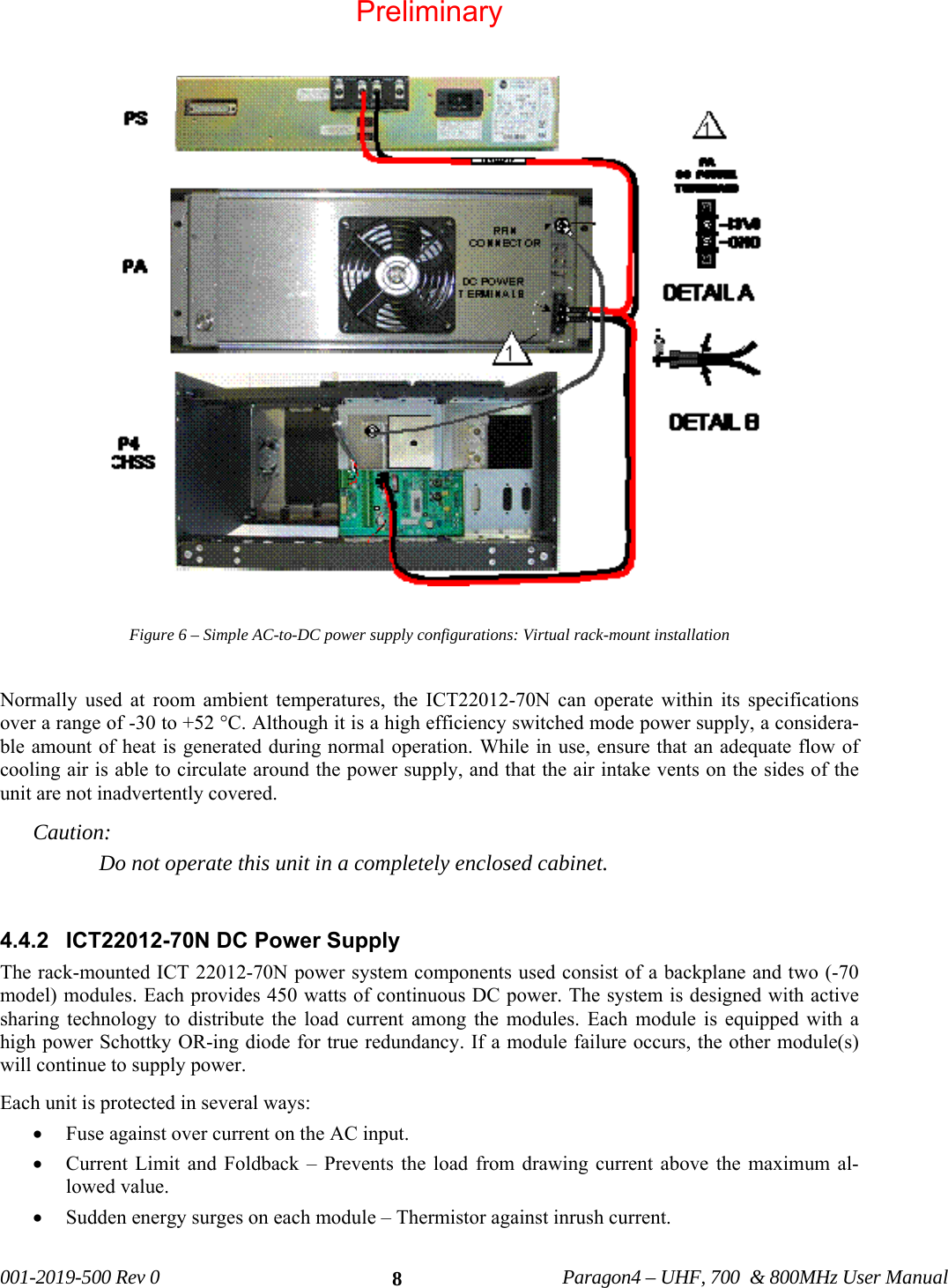
CalAmp Wireless Network BDP4-EXCT438 UHF HIGH SDR Exciter for BDP4 digital base station User Manual 120 20195 100 P4 700 May21x
CALAMP WIRELESS NETWORKS INC. UHF HIGH SDR Exciter for BDP4 digital base station 120 20195 100 P4 700 May21x
UserManual.wiki
>
CalAmp Wireless Network
>
BDP4 EXCT438 User Manual
user manual
Navigation menu
Upload a User Manual
Namespaces
Wiki Guide
HTML
PDF
Info
Views
User Manual
Discussion / Help
Navigation
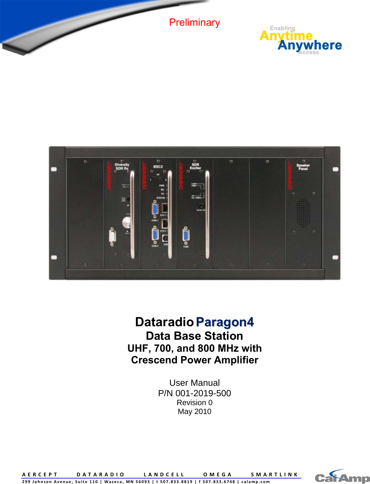
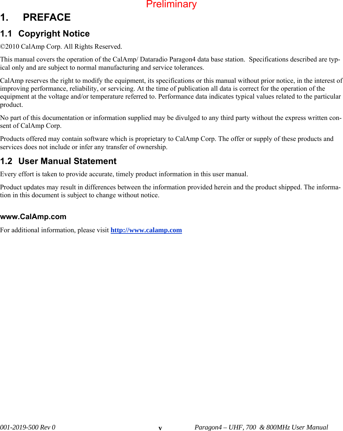
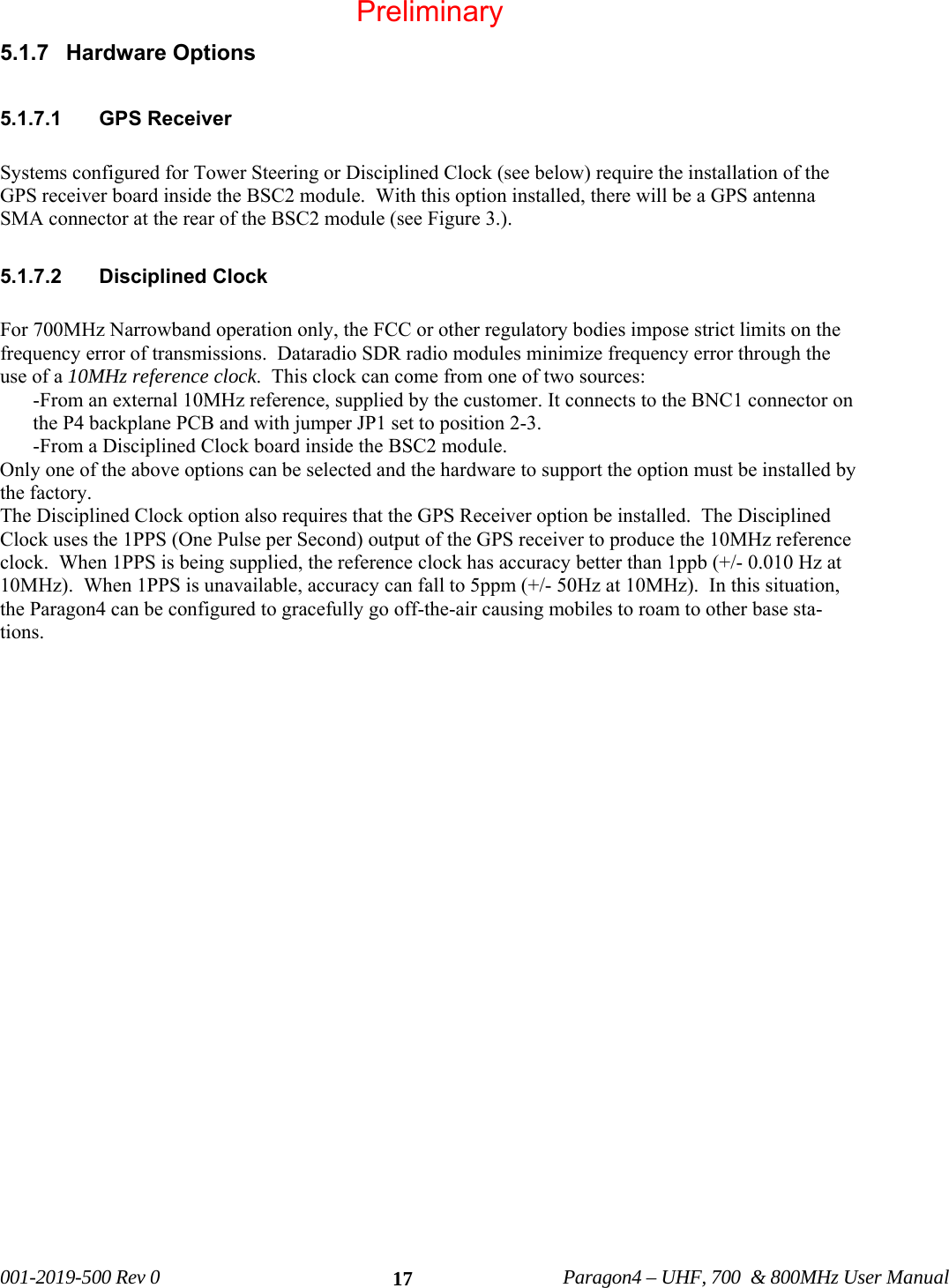
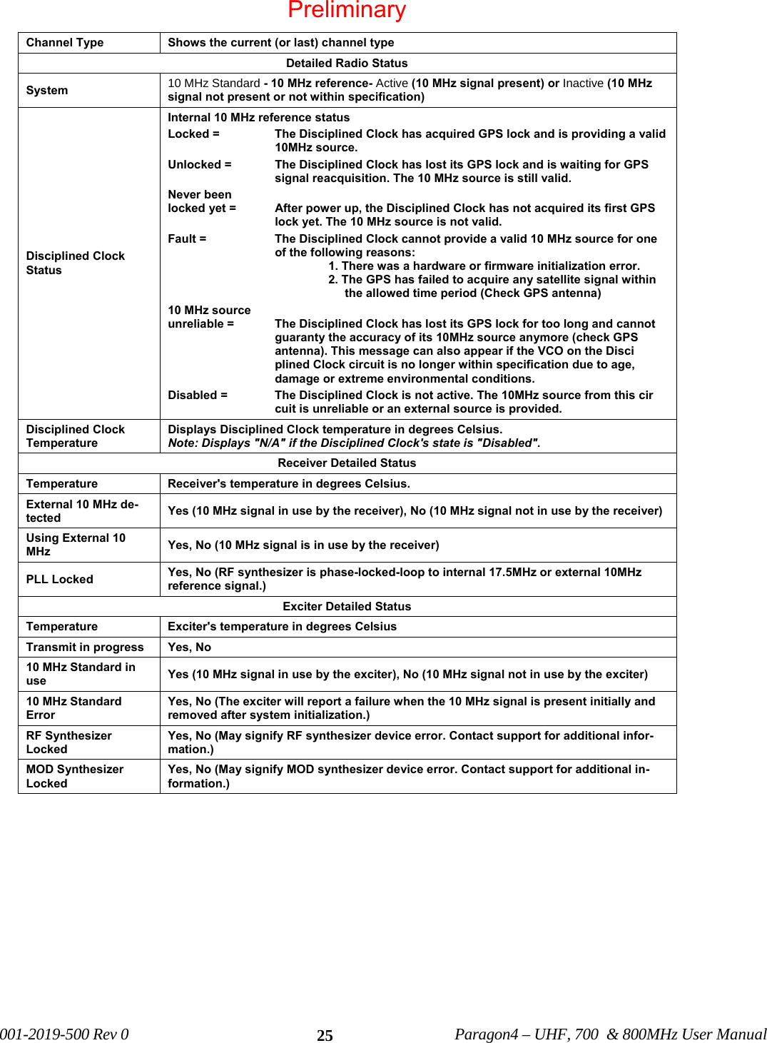
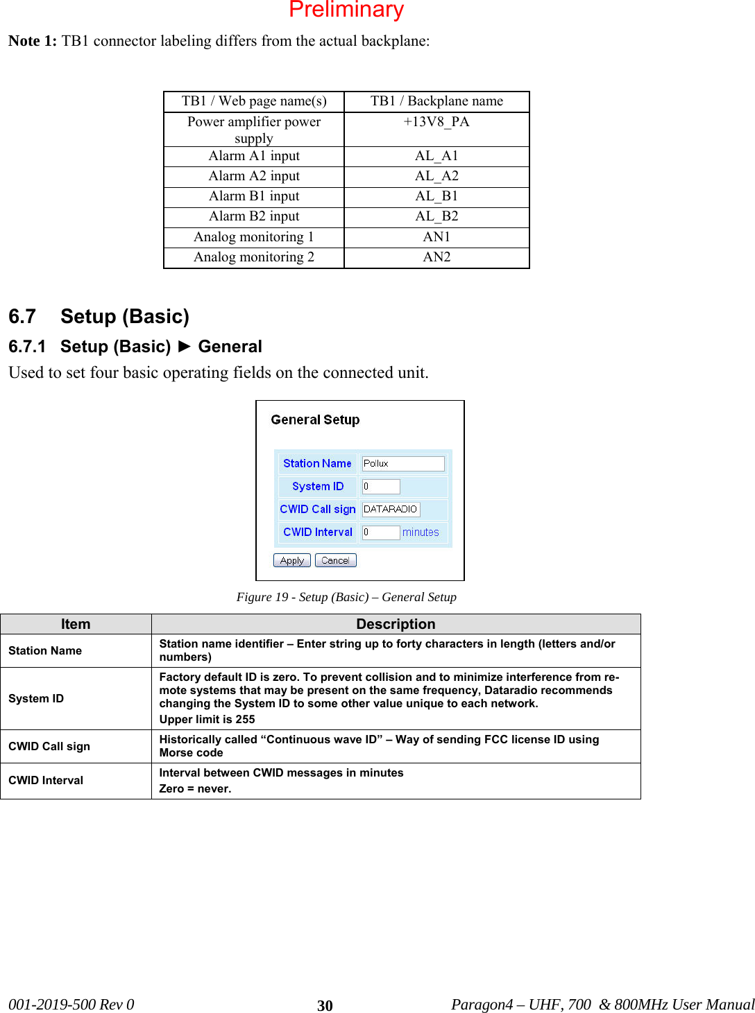
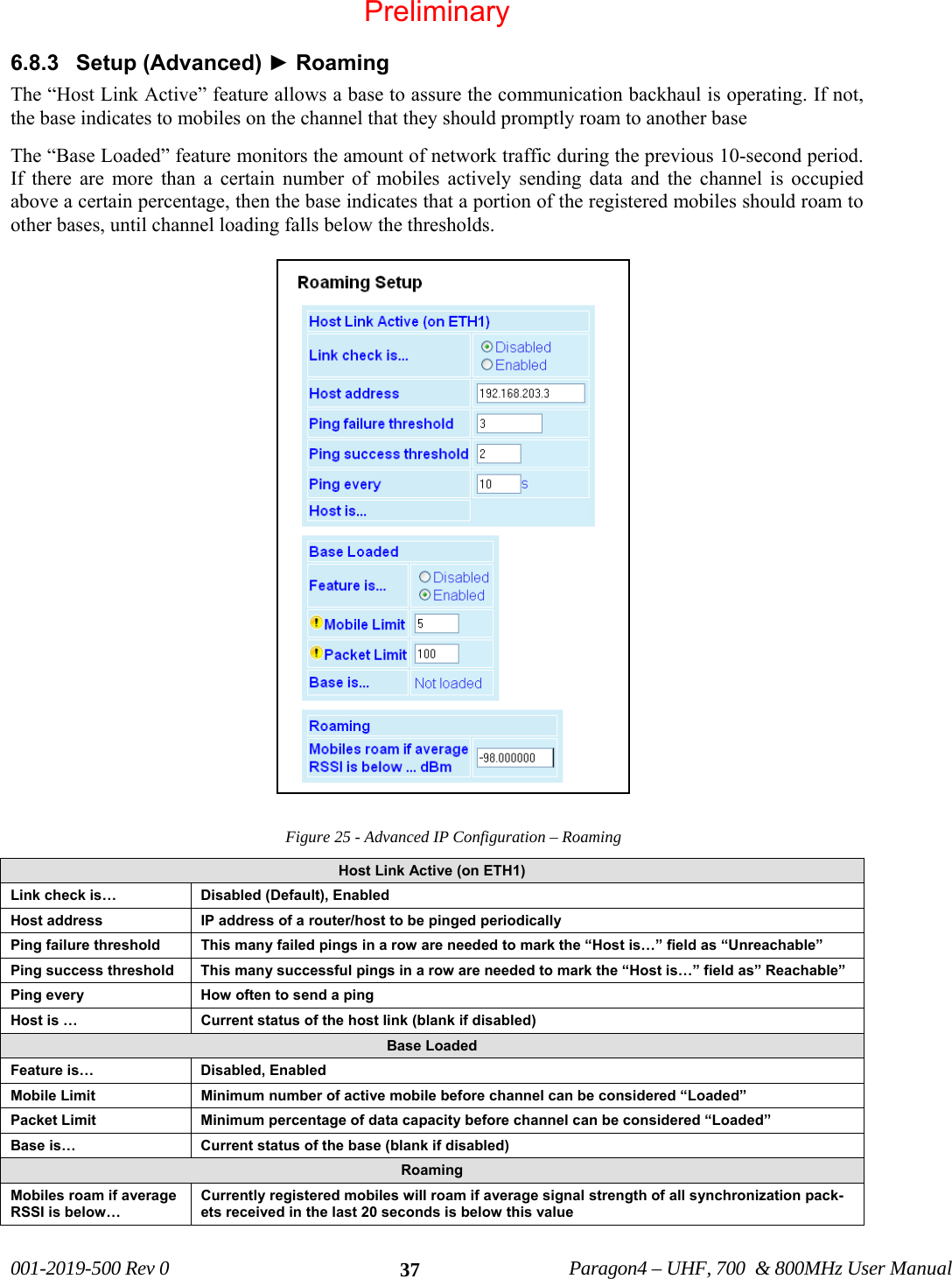
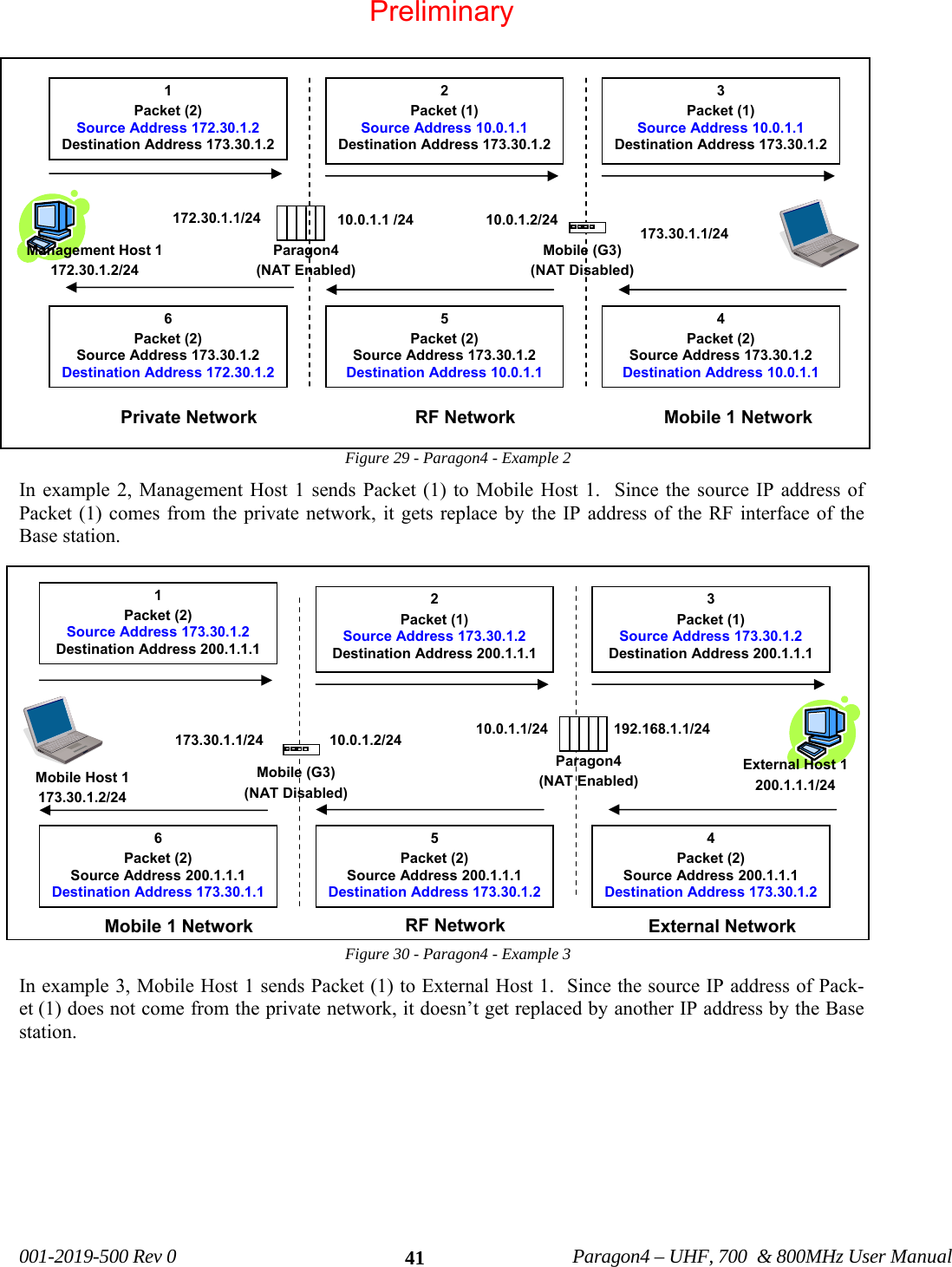
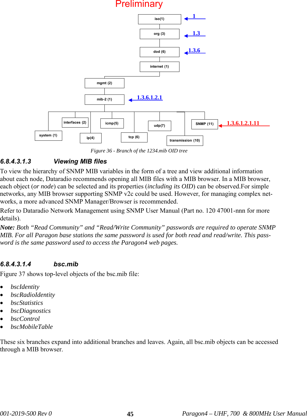
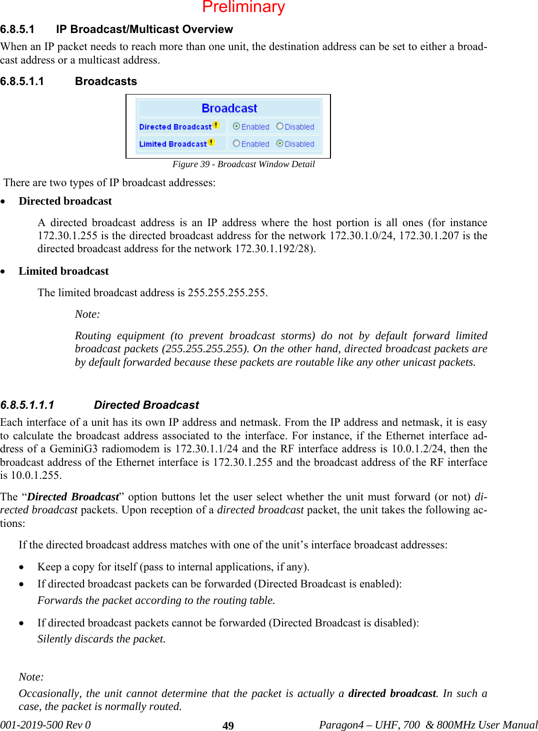
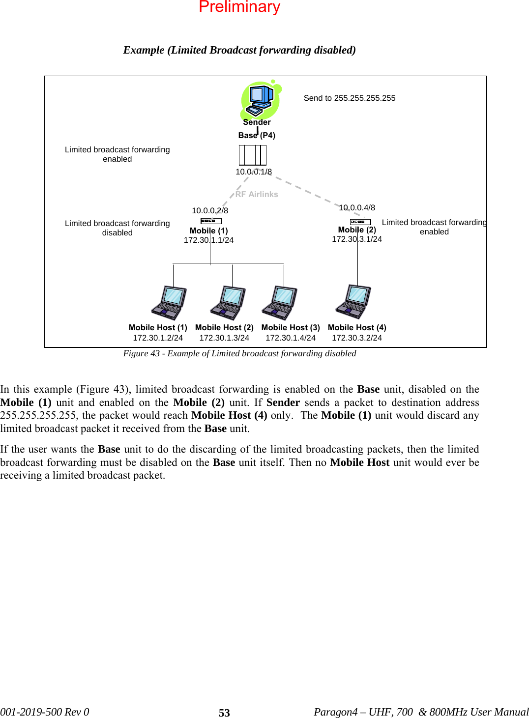
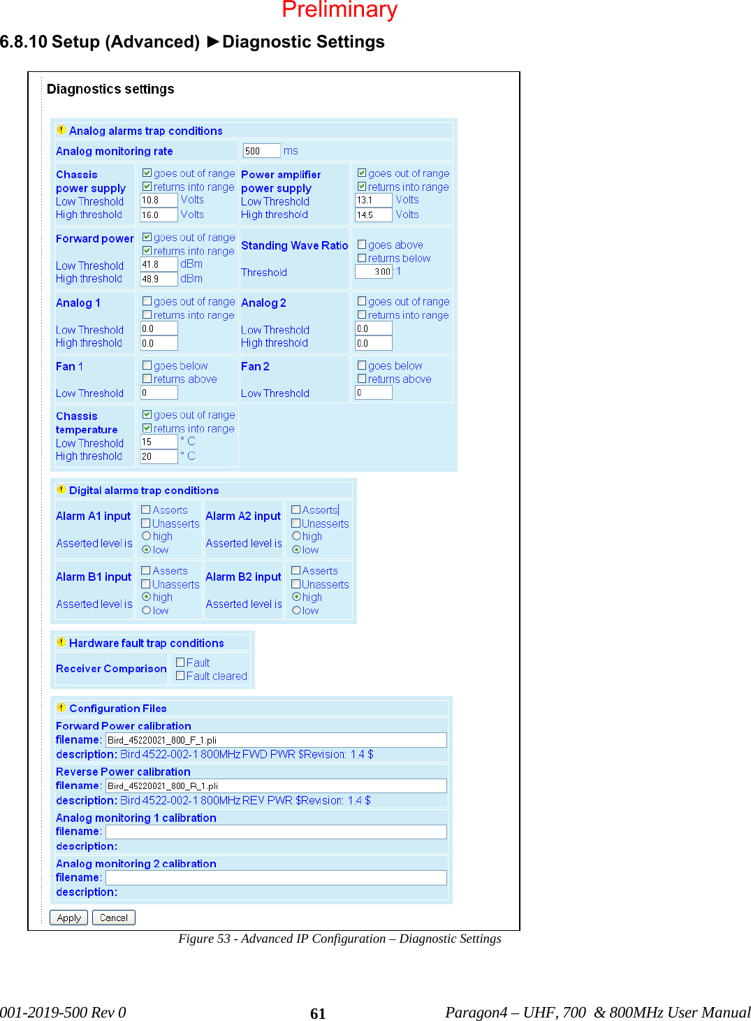
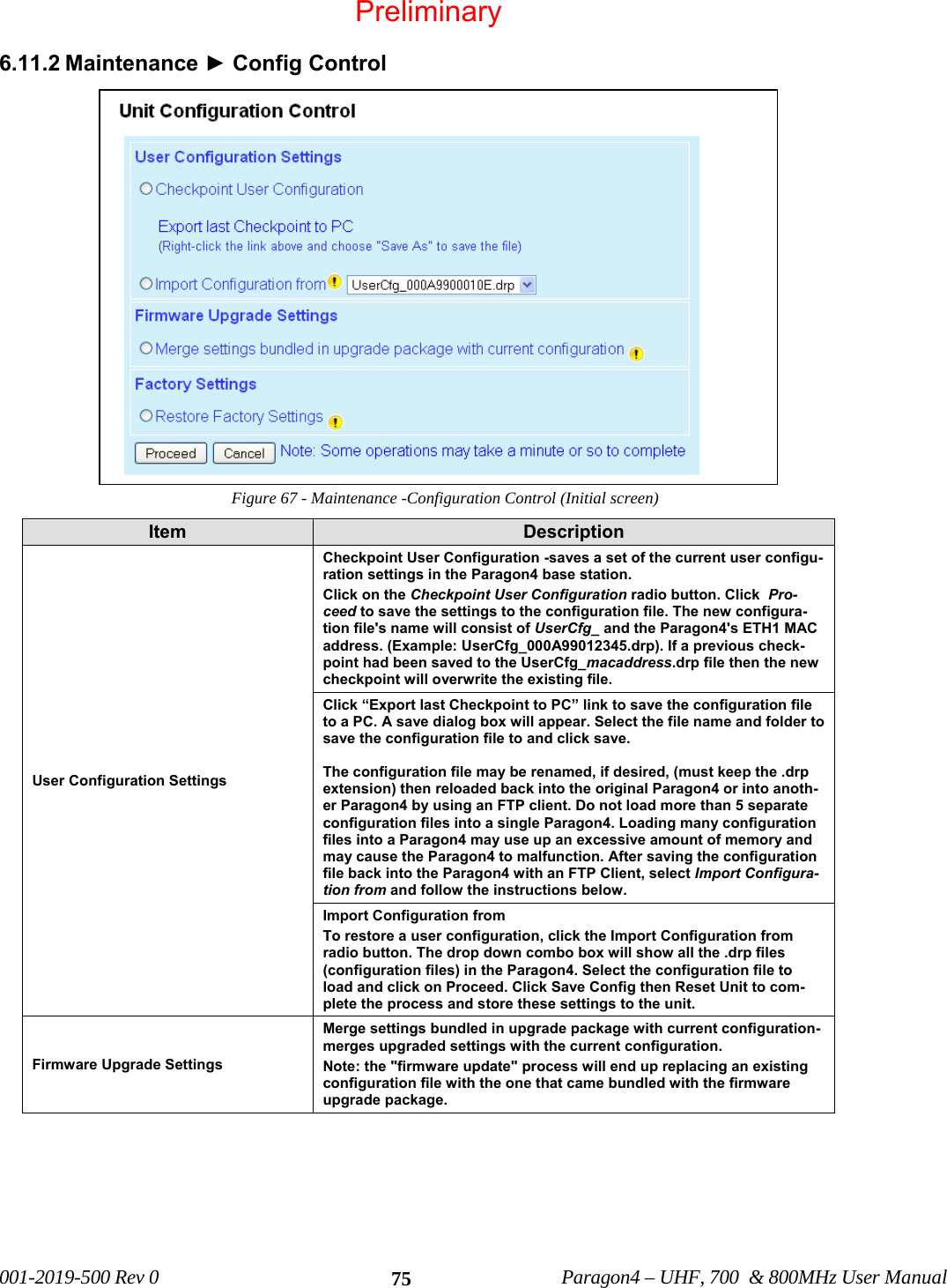
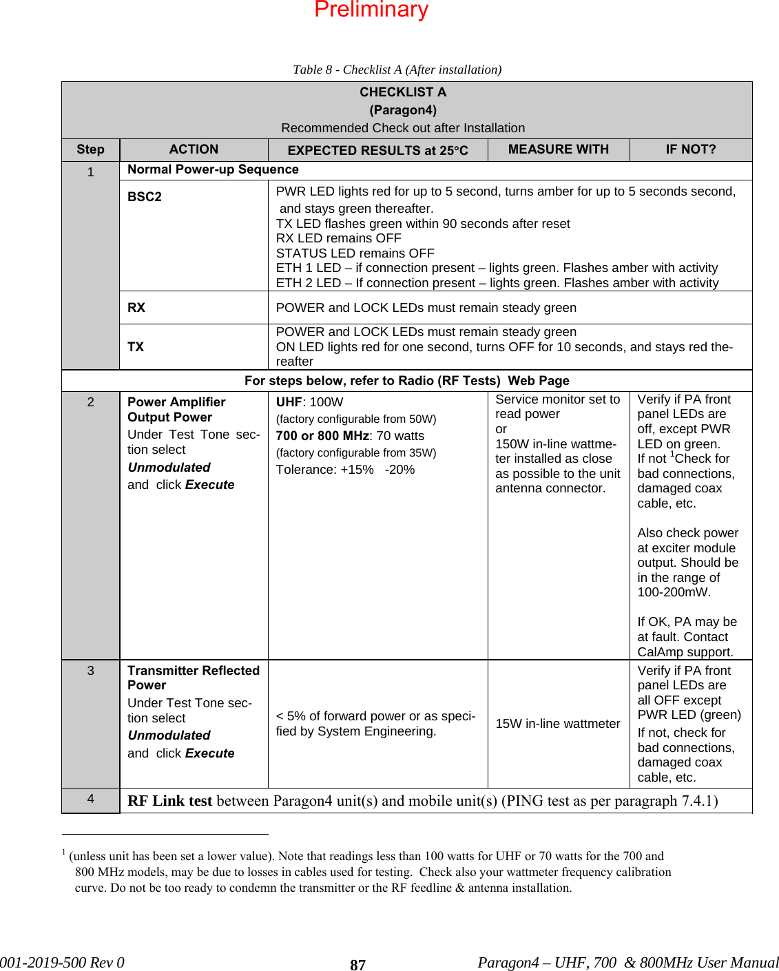
![001-2019-500 Rev 0 Paragon4 – UHF, 700 & 800MHz User Manual 63An example of a look-up table is presented in Table 5 with a corresponding graph in Figure 54 Table 5 - Sample Interpolation endpoints Figure 54 - Sample Interpolation curve Values in-between the data points are calculated using a straight line between the closest two known data points. At least 2 data points are required; however 10 or 20 data points (up to 50) are usually necessary (depending on the curves behavior). A look-up table can be created with a simple text editor, such as MS-Notepad, carefully following the guidelines presented below. The basic syntax is summarized in Table 5. • // symbol preceding any entry denotes comments. • [c] symbol preceding a string of up to 80 characters denotes file description. This string will be dis-played under “description” field on the “Diagnostics Settings” page of the Pargon3 web interface. • [u] symbol preceding a string of up to 15 characters denotes the desired unit of measure. • [n] symbol preceding an integer denotes the number of entries in the look-up table. • Data points are filled in as {Xin, Yout} pairs. Each pair occupies a line and counts one space in be-tween its elements: Xin1Yout1 Xin2 Yout2 Xin3 Yout3 …….. • The number of {Xin, Yout} pairs must correspond to the index ([n]) entered. • Empty lines are not accepted-use comments for formatting. • Duplicate Xin values are not accepted. Xin (Volts) Yout (Desired Units) 0.0 0.0 0.2 1.0 0.375 2.0 0.530 3.0 0.530 4.0 00.511.522.533.544.50 0.2 0.4 0.6 0.8Xin (Volts)Yout (Desired Units)Preliminary](https://usermanual.wiki/CalAmp-Wireless-Network/BDP4-EXCT438/User-Guide-1290807-Page-71.png)
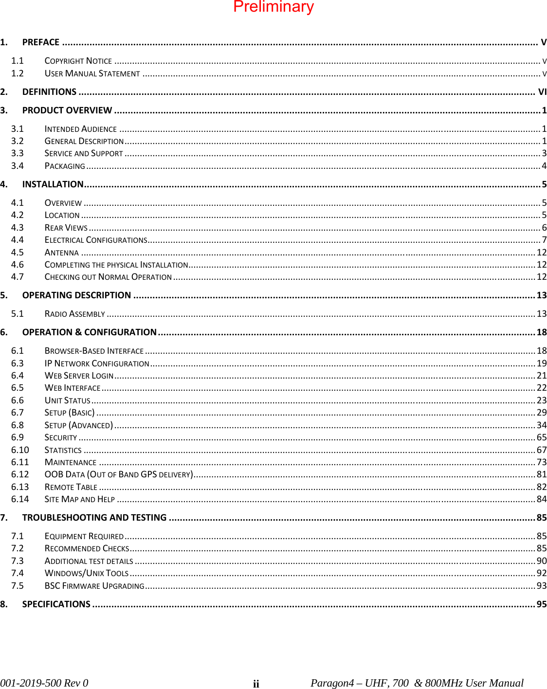
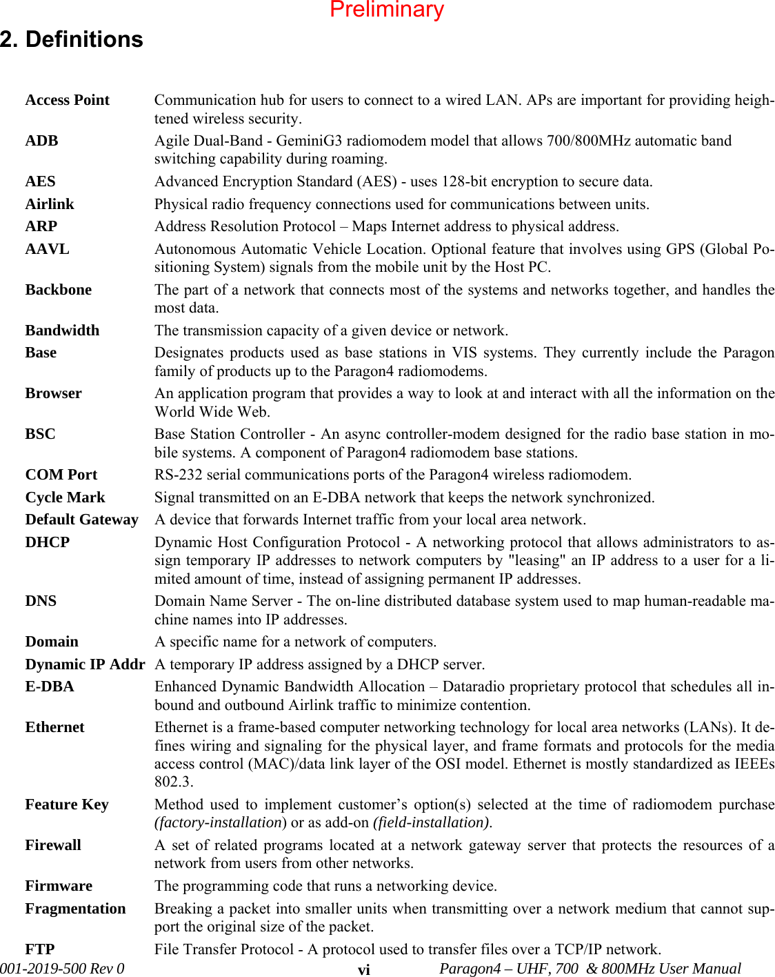
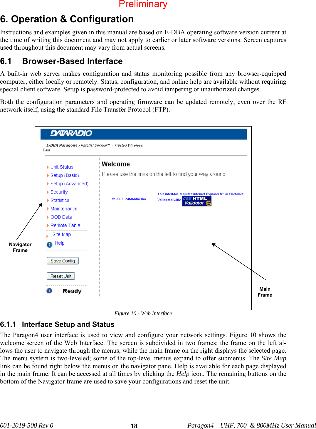
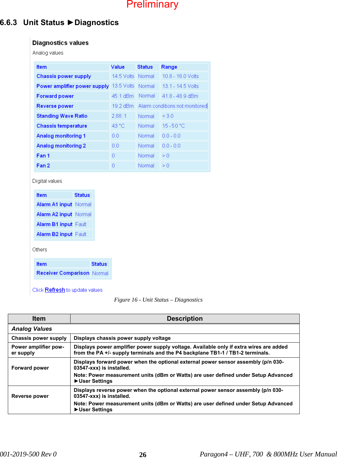
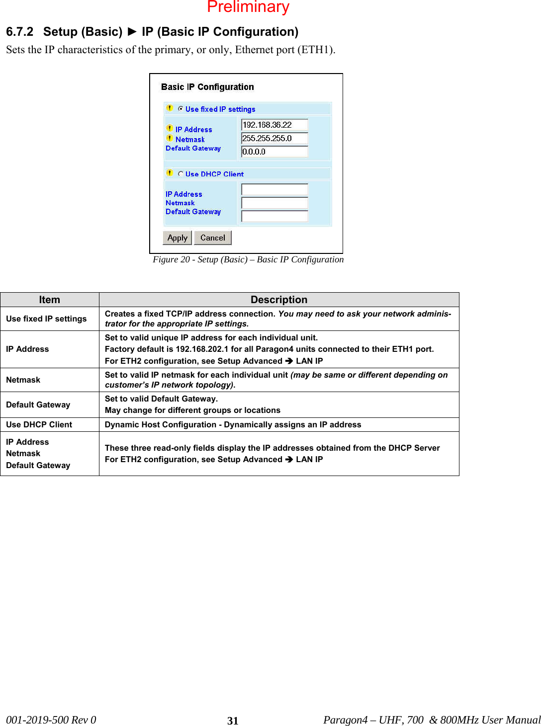
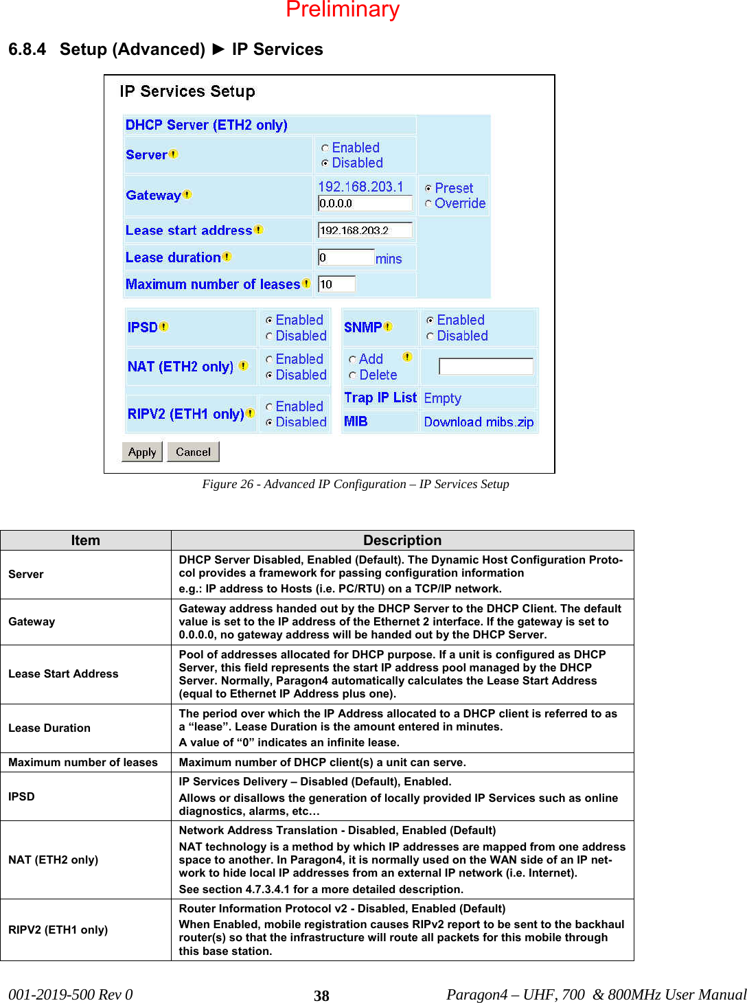
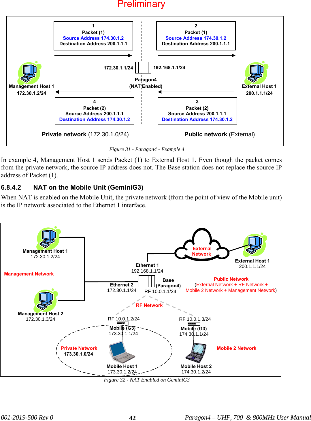
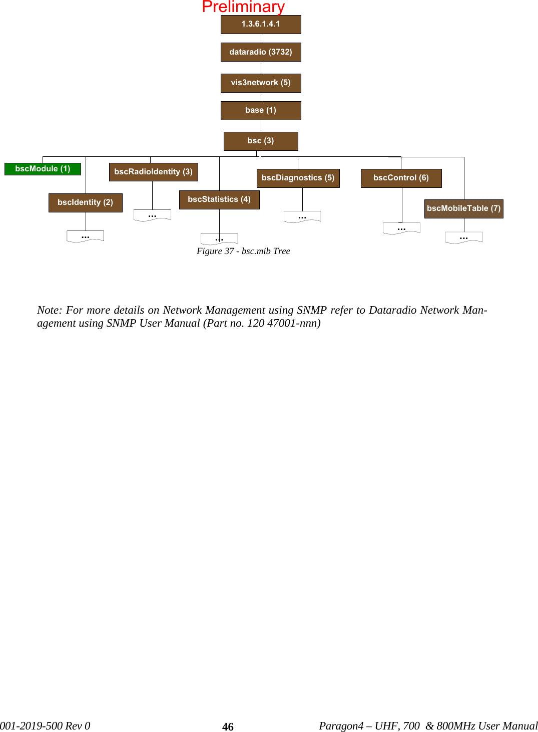
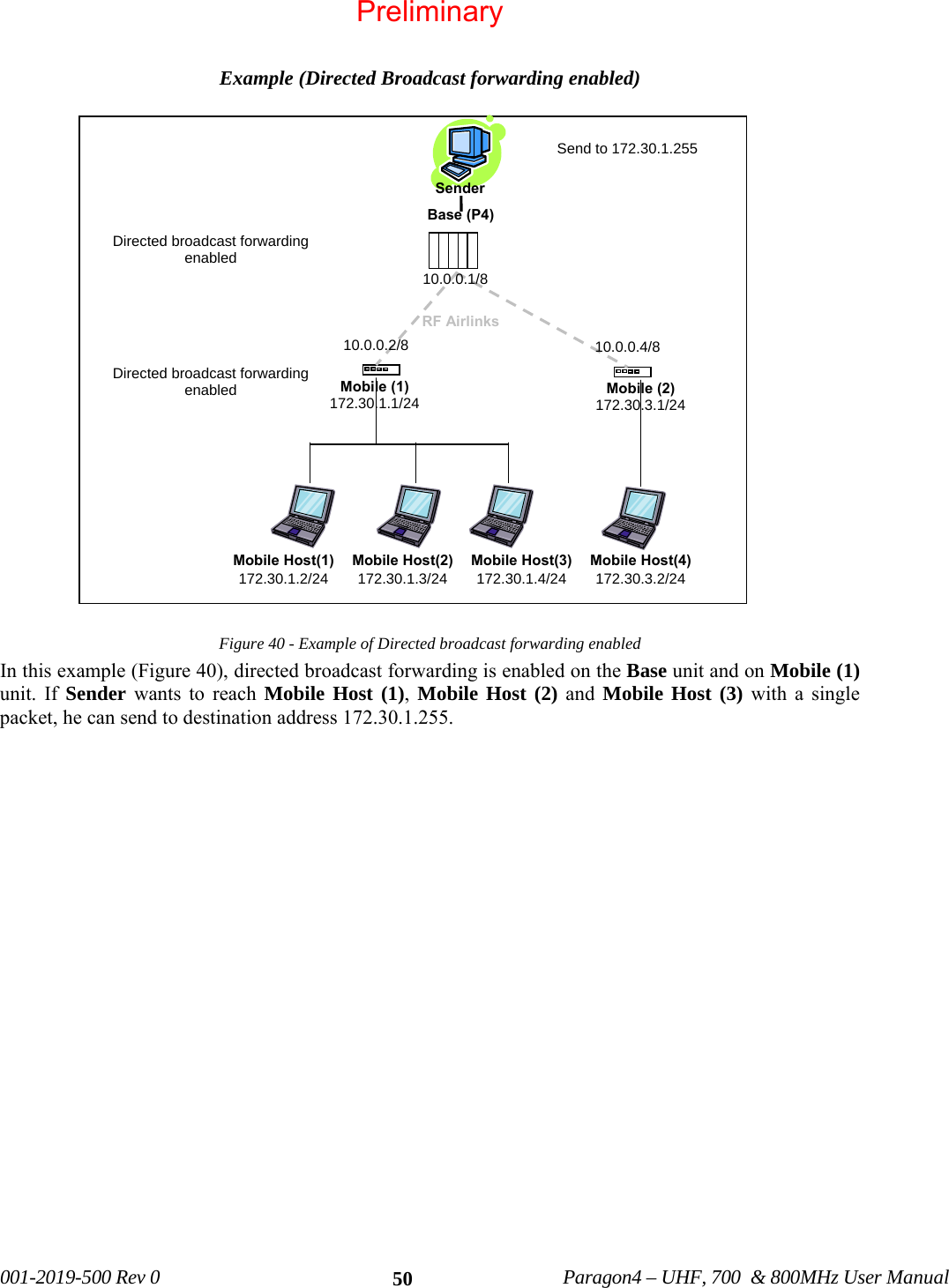
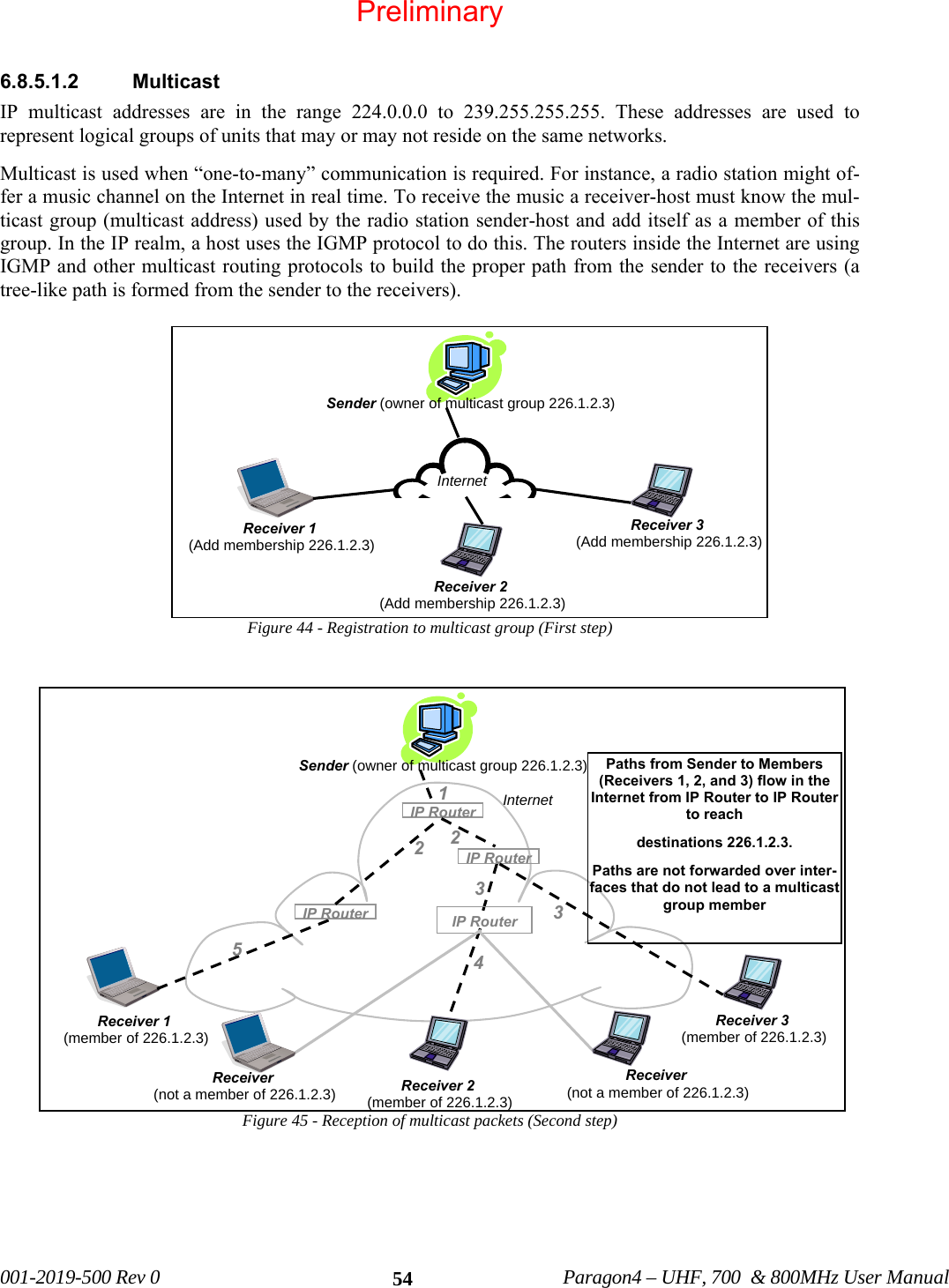
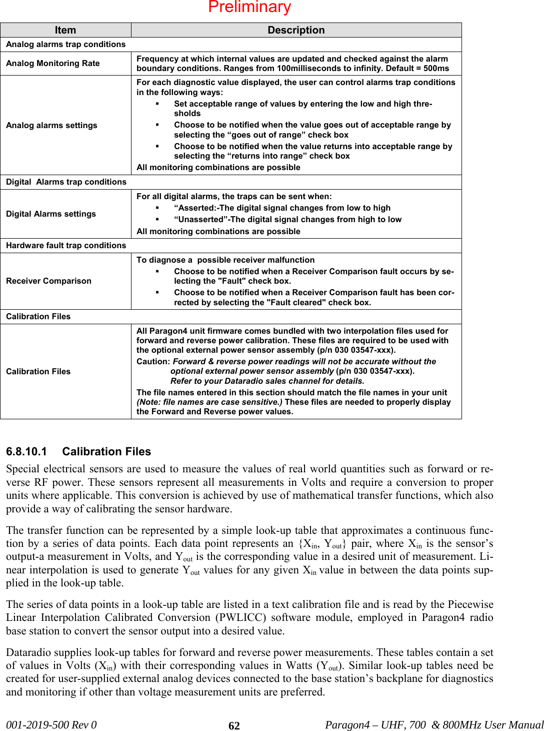
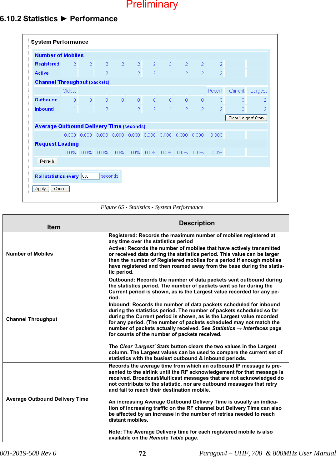
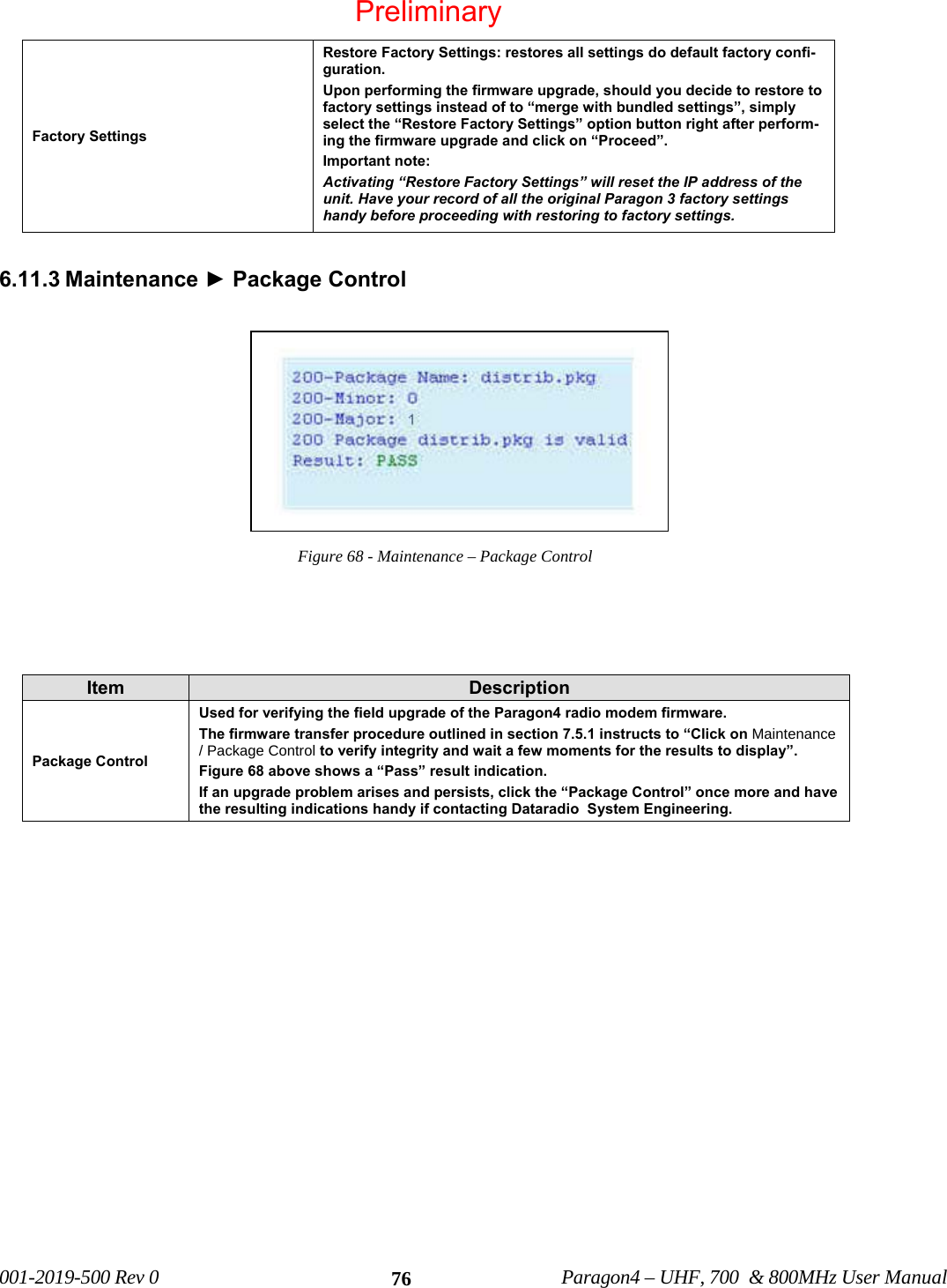
![001-2019-500 Rev 0 Paragon4 – UHF, 700 & 800MHz User Manual 64• When complete, use the “Save As” command. • The file name is case-sensitive and spaces are not allowed. • The file name should be saved under .pli extension. • The file should be uploaded into a unit using FTP transfers. • The file’s name should be entered under “Analog monitoring 1 calibration” (and/or “Analog monitor-ing 2 calibration”) field on the Diagnostic page of the Paragon4 web interface. Table 6 - PLICC Syntax Syntax Description // <comment> Comments. Optional [c] <name> Descriptive name of the look-up table (string of 80 characters max). This field will appear under the “description” field on the Diagnostics Settings” page of the Pargon3 web interface. Optional [u] <unit> Unit of measure (string of 16 char maximum). Optional [n] <index> Number of entries in the table (2 minimum, 50 maximum). Required Failure to comply with the guidelines described above may result in the following errors: Table 7 - Possible Error messages Error Description No file found The file name entered is not found on the unit. Bad header or bad file format found. Syntax Error . No data found. No data entered in the file (less than 2 data points). More than 50 segments found in file. The file counts more than 50 data points. Duplicate X values found in data. The file contains duplicate Xin values. A sample calibration file is presented in Figure 55. Please note the following: 1. “Volts to watts conversion” will appear under the “description” field on the “Diagnostics Settings” page of the Pargon3 web interface. 2. This look-up table contains a set of values in Volts with their corresponding values in Watts. 3. This look-up table contains five data points. 4. The number of data points should correspond to the index (entered under [n]). All Xin entries (voltage values) must be unique. // file name: sample_calibration_file.pli // Revision: N.NN // Date: YYYY/MM/DD // Other Comments [c]Volts to watts conversion [u]Watts [n]5 0.000 0.0 0.200 1.0 0.375 2.0 0.530 3.0 0.530 4.0 Figure 55 - Sample calibration file 2 3 1 4 Preliminary](https://usermanual.wiki/CalAmp-Wireless-Network/BDP4-EXCT438/User-Guide-1290807-Page-72.png)
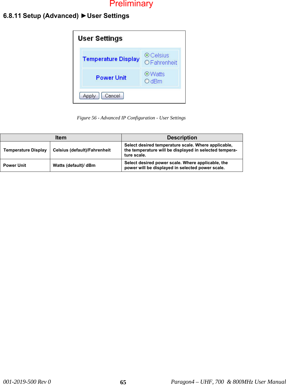
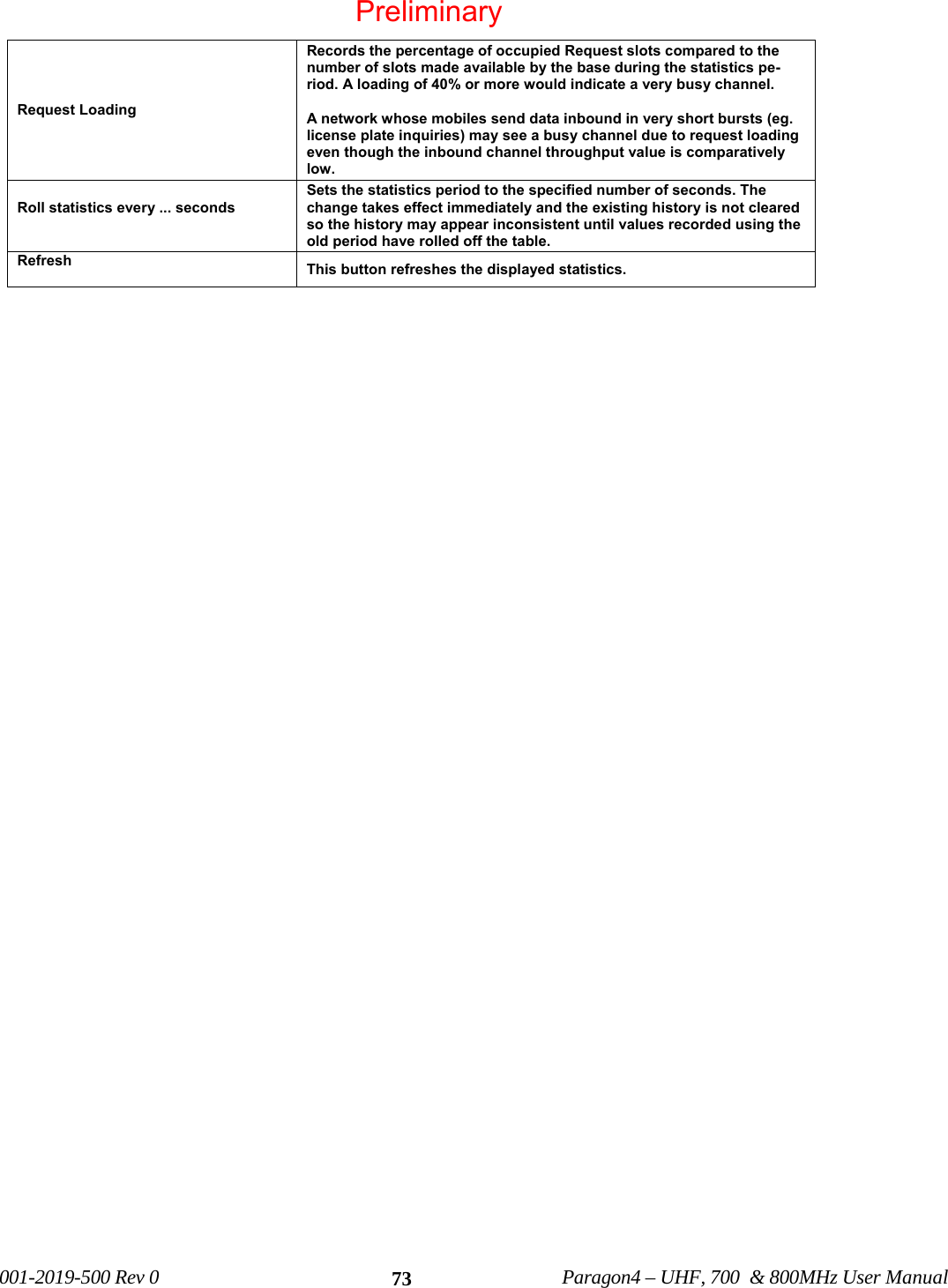
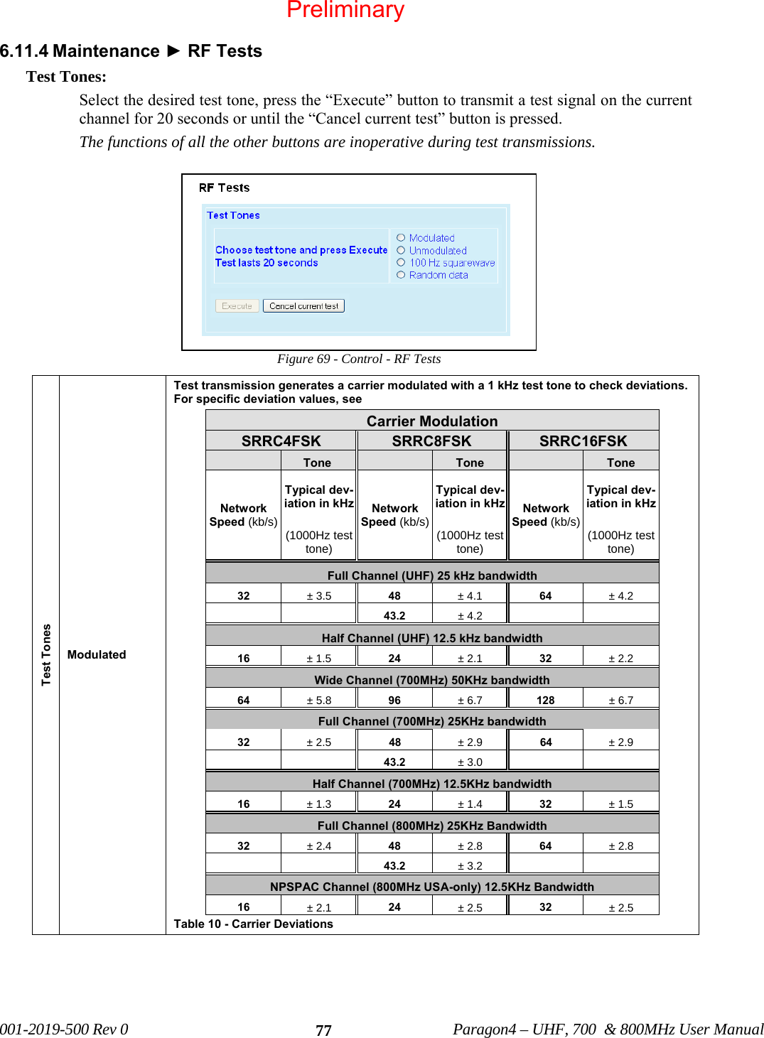
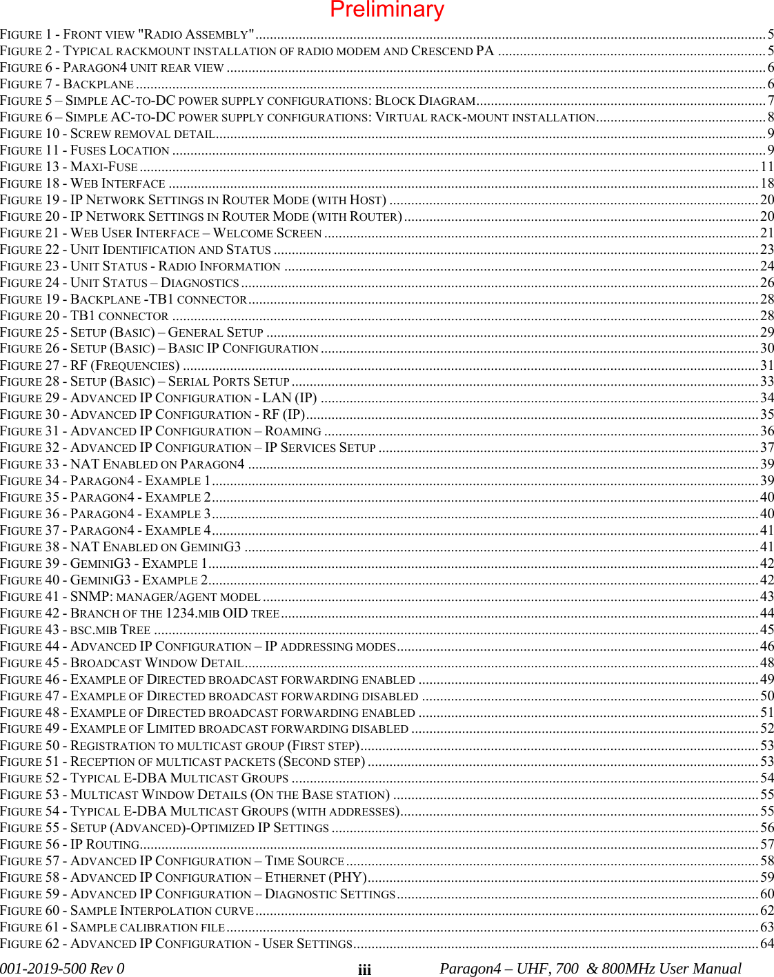
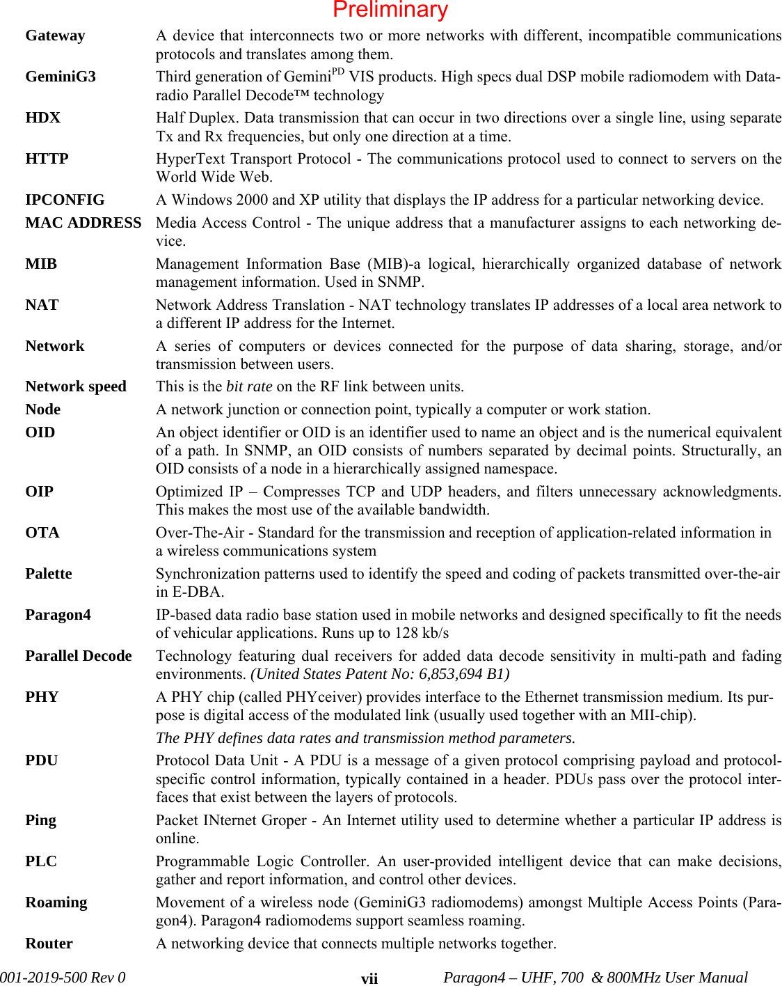
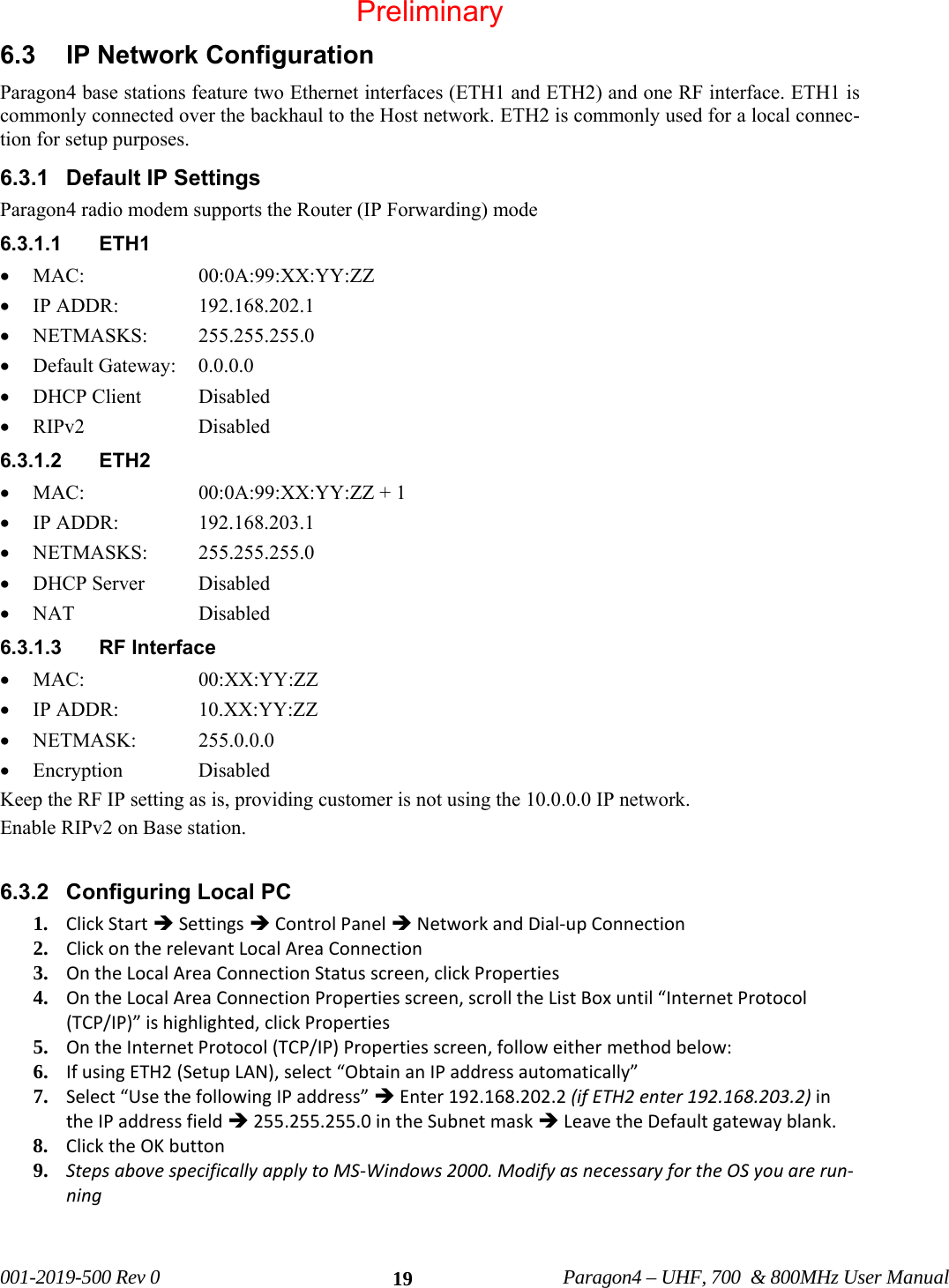
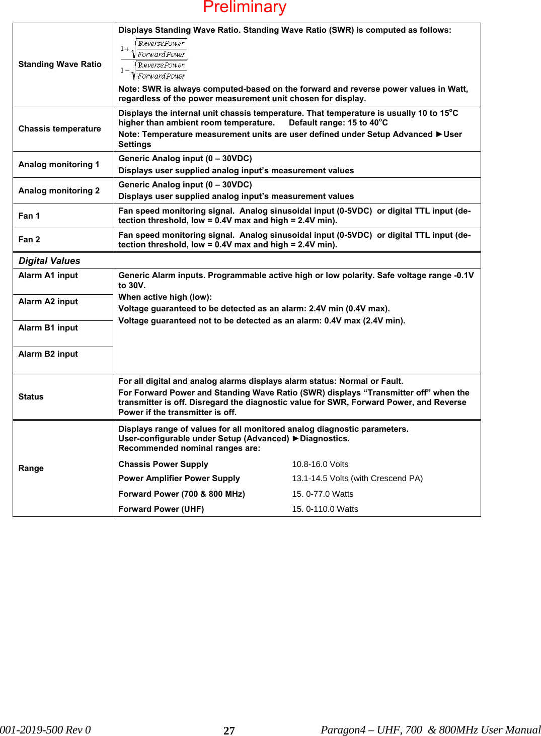
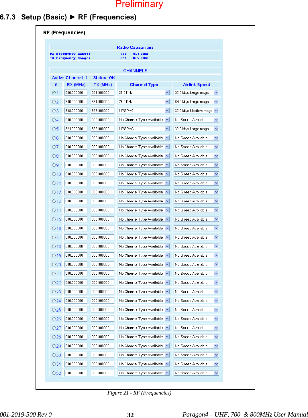
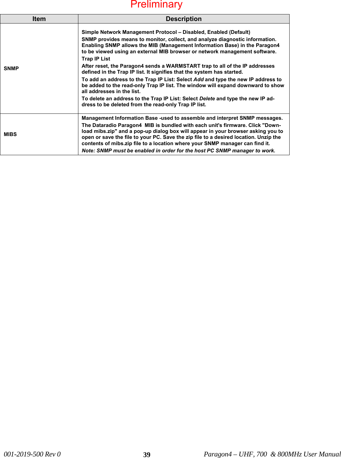
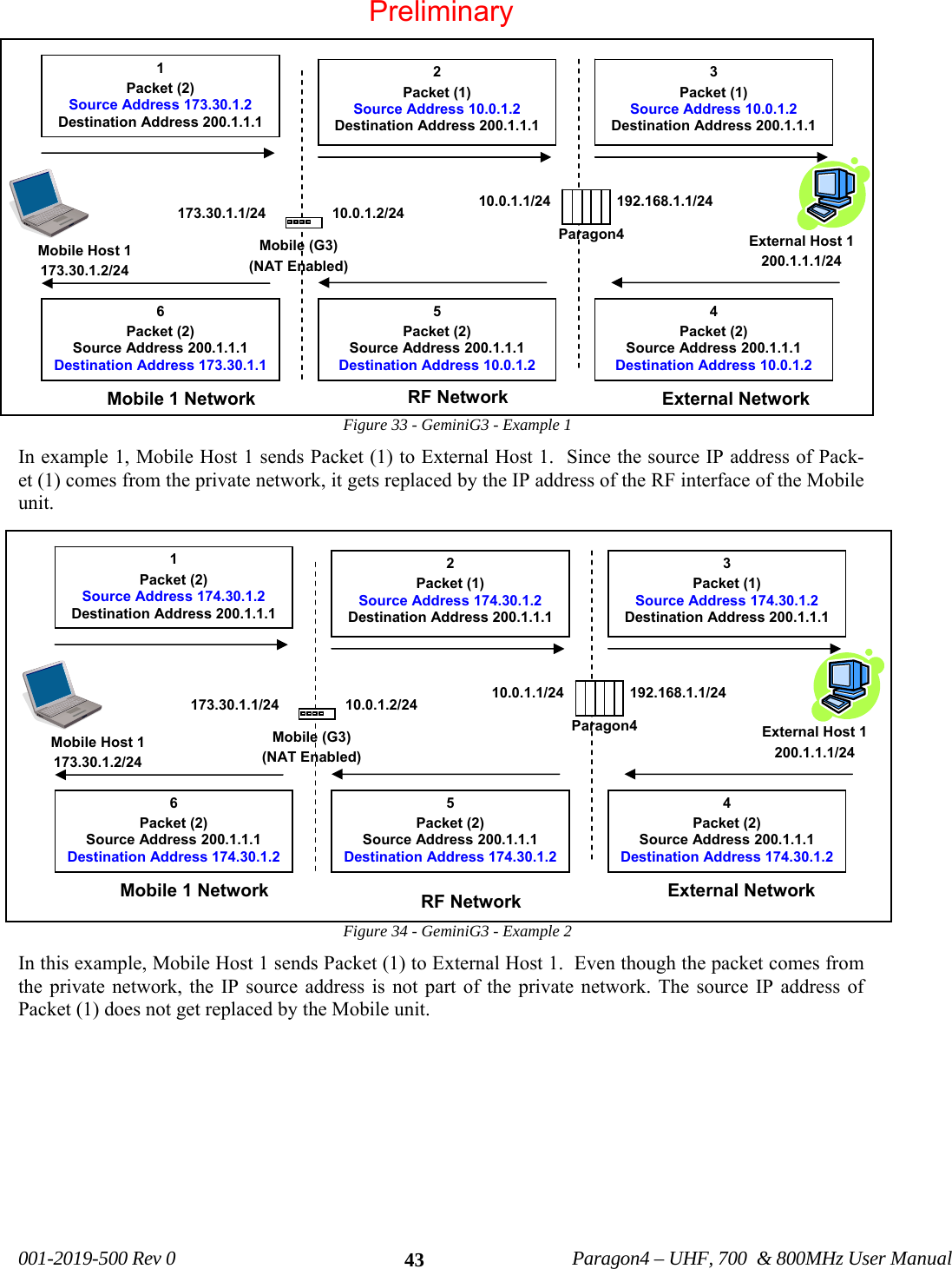
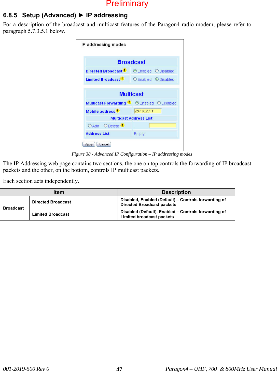
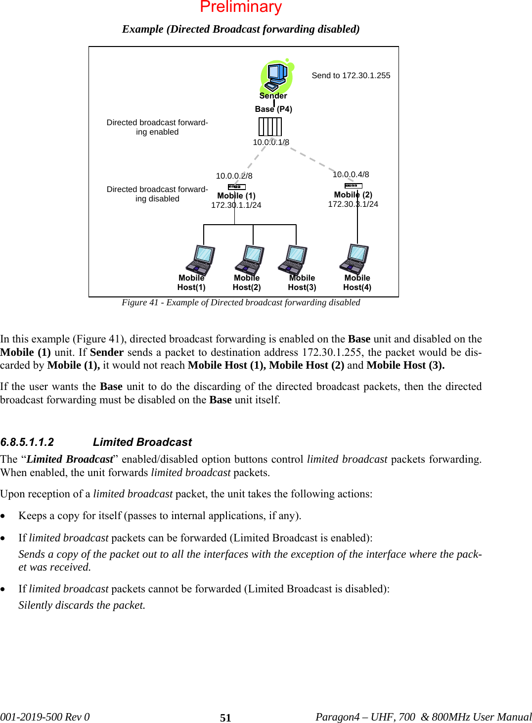
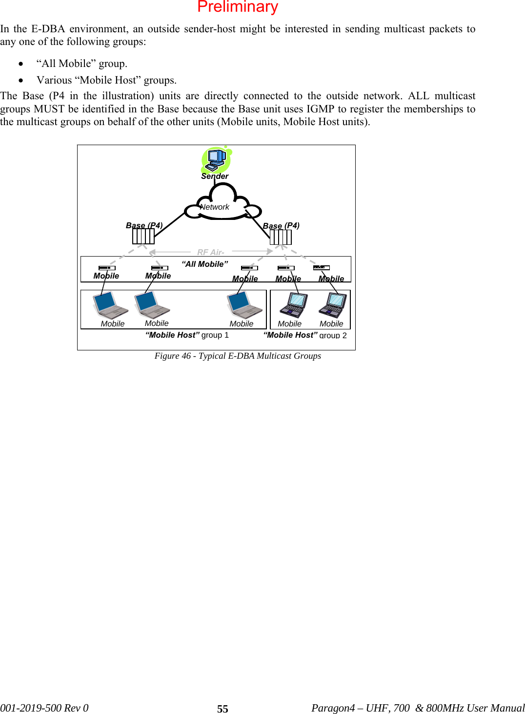
![001-2019-500 Rev 0 Paragon4 – UHF, 700 & 800MHz User Manual 81Note: Log information will be preserved across system restarts or faults. The general categories of events that can be found in the system log are: • Asserts: undesirable conditions (faults) • Resets: reasons for various system resets • Others: warnings, recovery from a fault, etc 6.11.7.1.1 Asserts An Assert log entry will normally display an exit code, a module number, and a line number indicating where the error occurred. See Figure 74 for an example of an Assert log entry. This information will al-low Dataradio support team to determine the component and the reason of an error so that a corrective action could be recommended. Figure 74 - An Assert type system log entry Note: “0x0” exit code signifies normal (non-faulty) system exit. 6.11.7.1.2 Resets A Paragon4 unit may be reset manually (through the Web interface, a telnet shell, or SNMP control) or automatically (as a result of the unit’s own monitoring facilities). Below are some examples of Reset log entries: Reset issued by a shell command: [5 1970-01-01 01:03:45 3827.924 37 C] stationReset: board hard reset Reset issued through the WEB Interface: [10 1970-01-10 21:49:00 856116.827 38 C] HTTP server reset [11 1970-01-10 21:49:00 856116.842 38 C] Exit... 0x0 Reset issued by an SNMP MIB browser: [14 2007-09-17 16:25:17 631.641 34 C] SNMP: board hard reset Module NumberLine NumberExit CodePreliminary](https://usermanual.wiki/CalAmp-Wireless-Network/BDP4-EXCT438/User-Guide-1290807-Page-89.png)
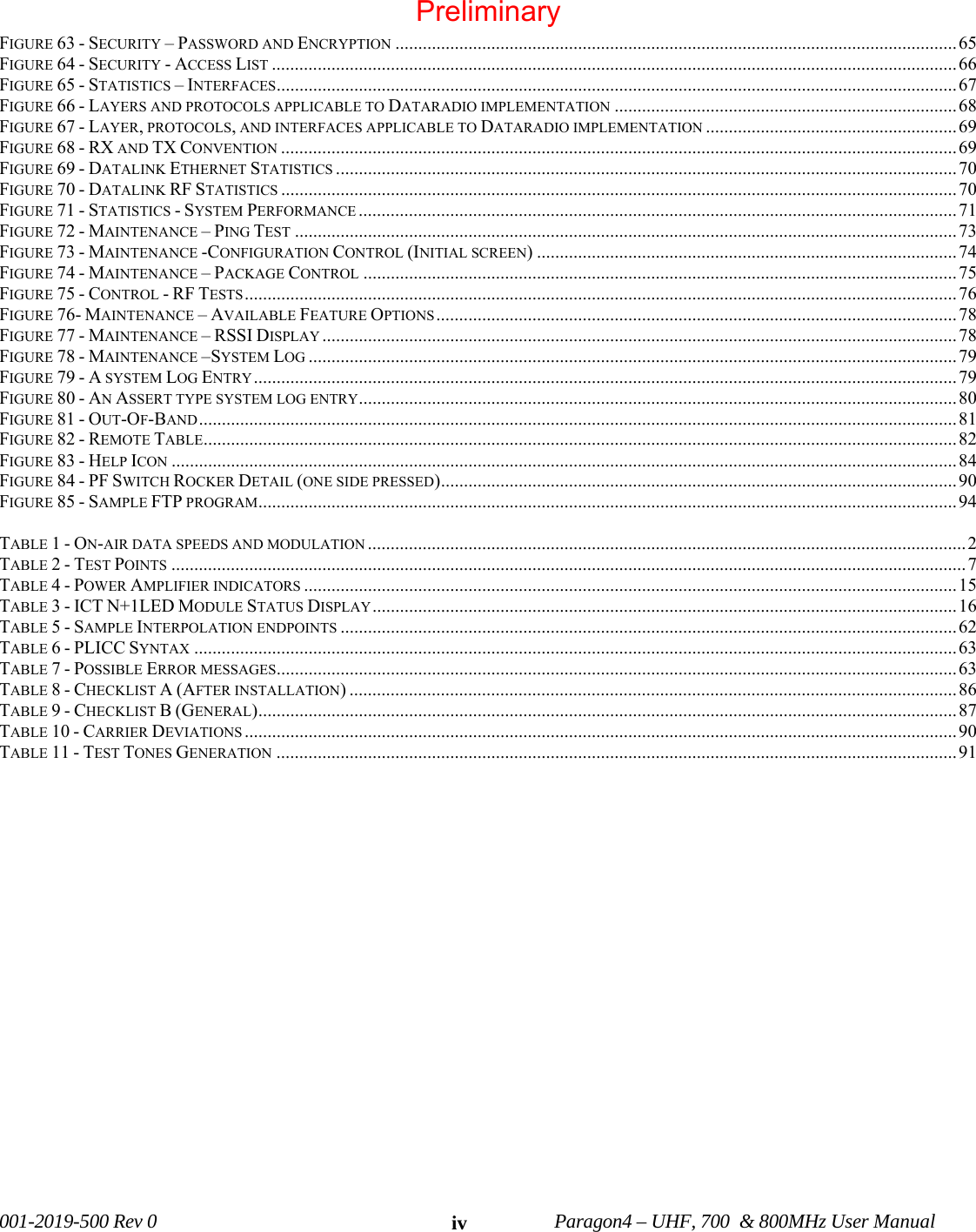
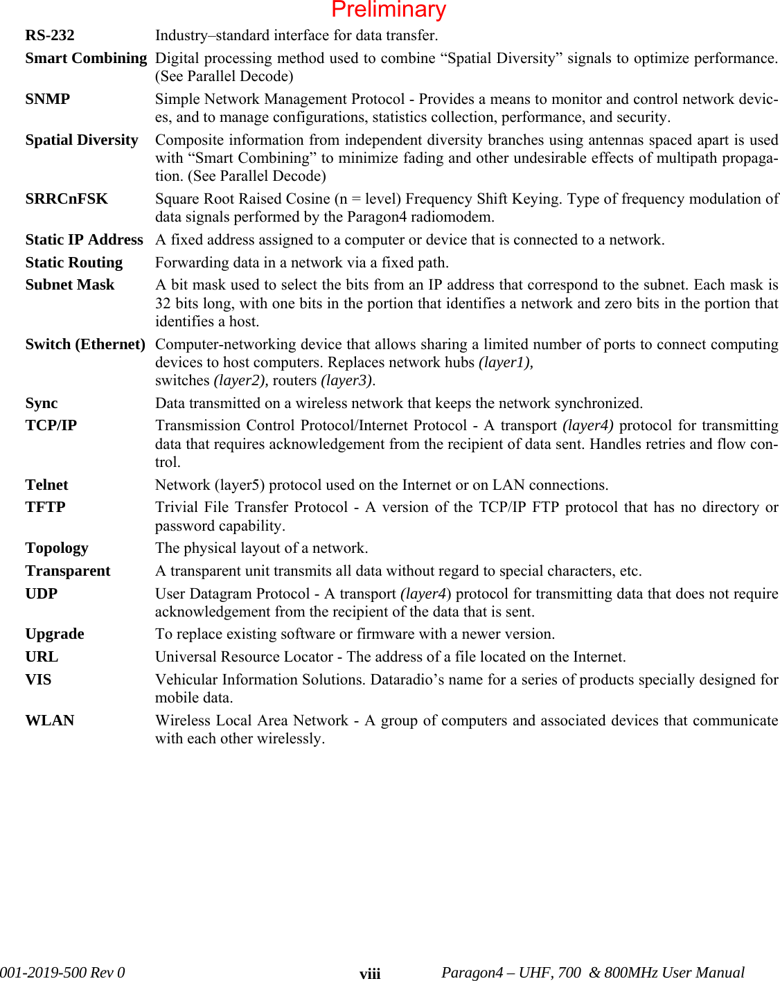
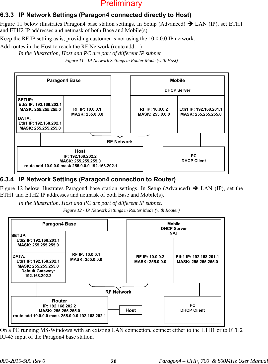
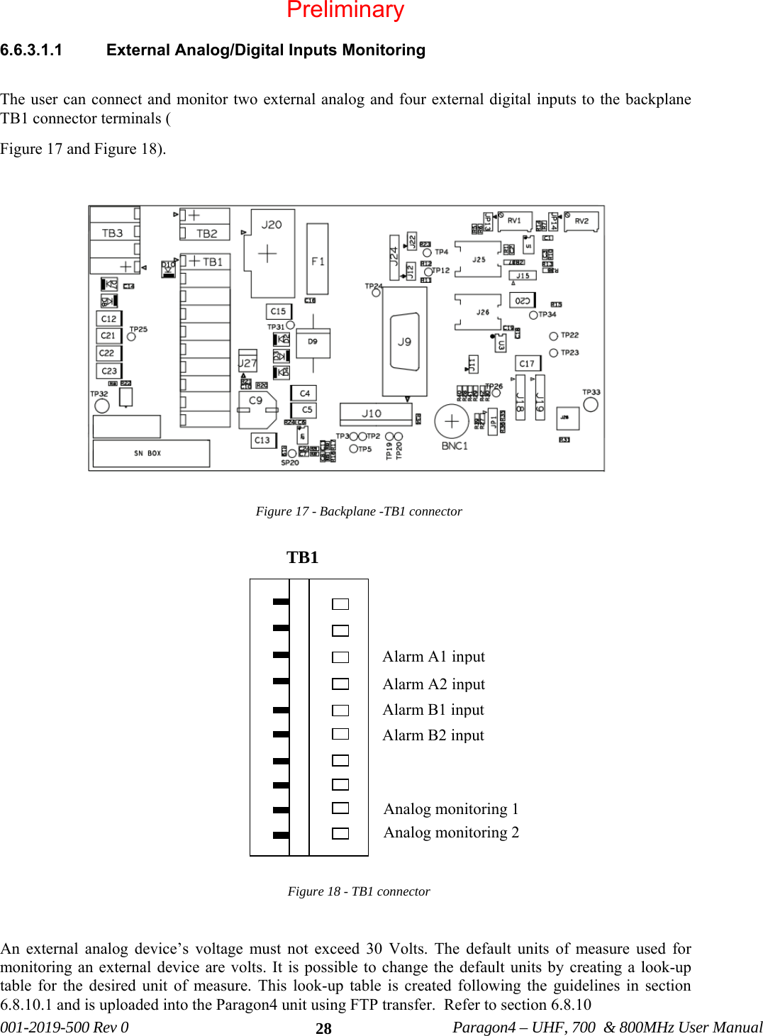
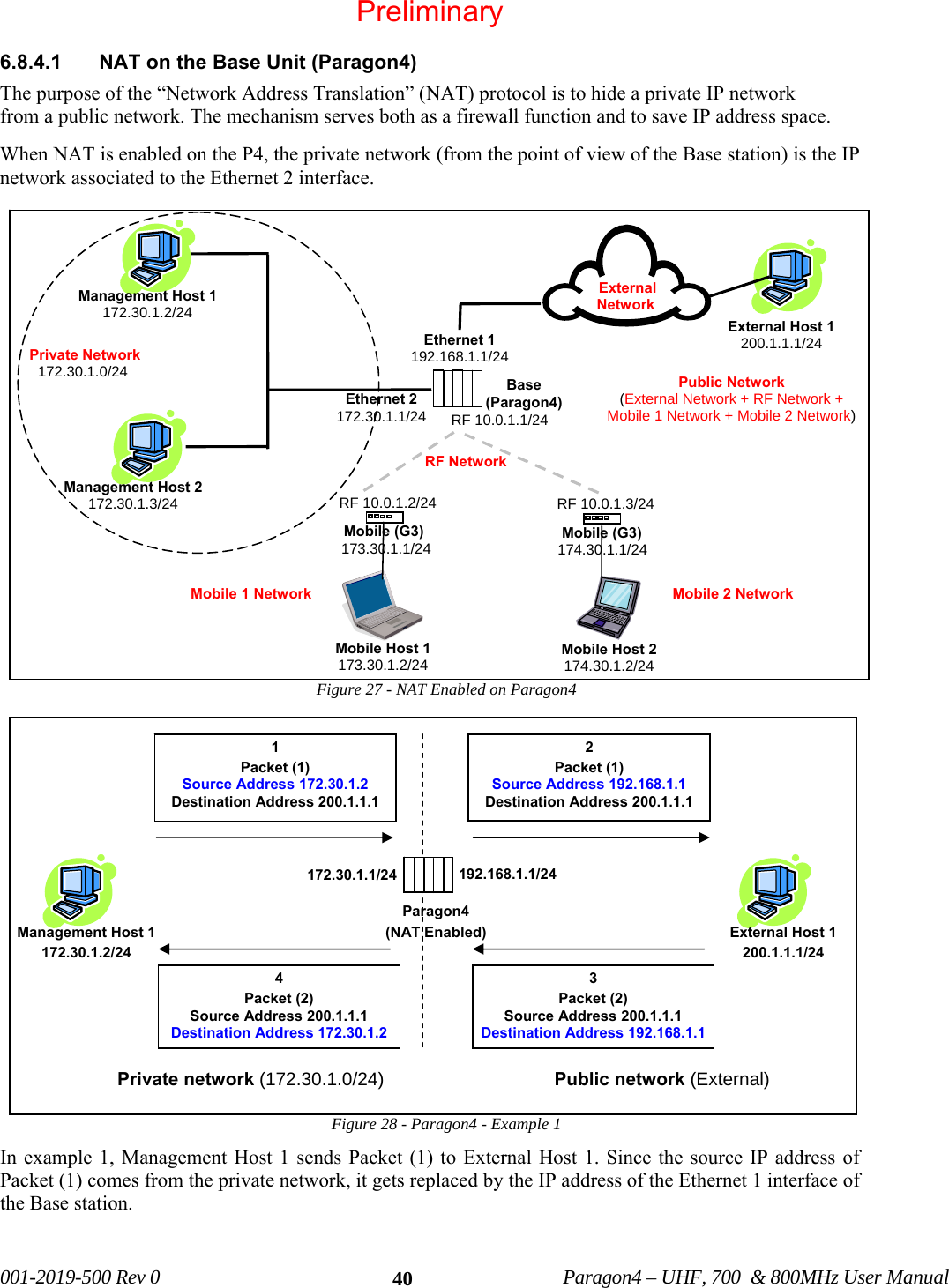
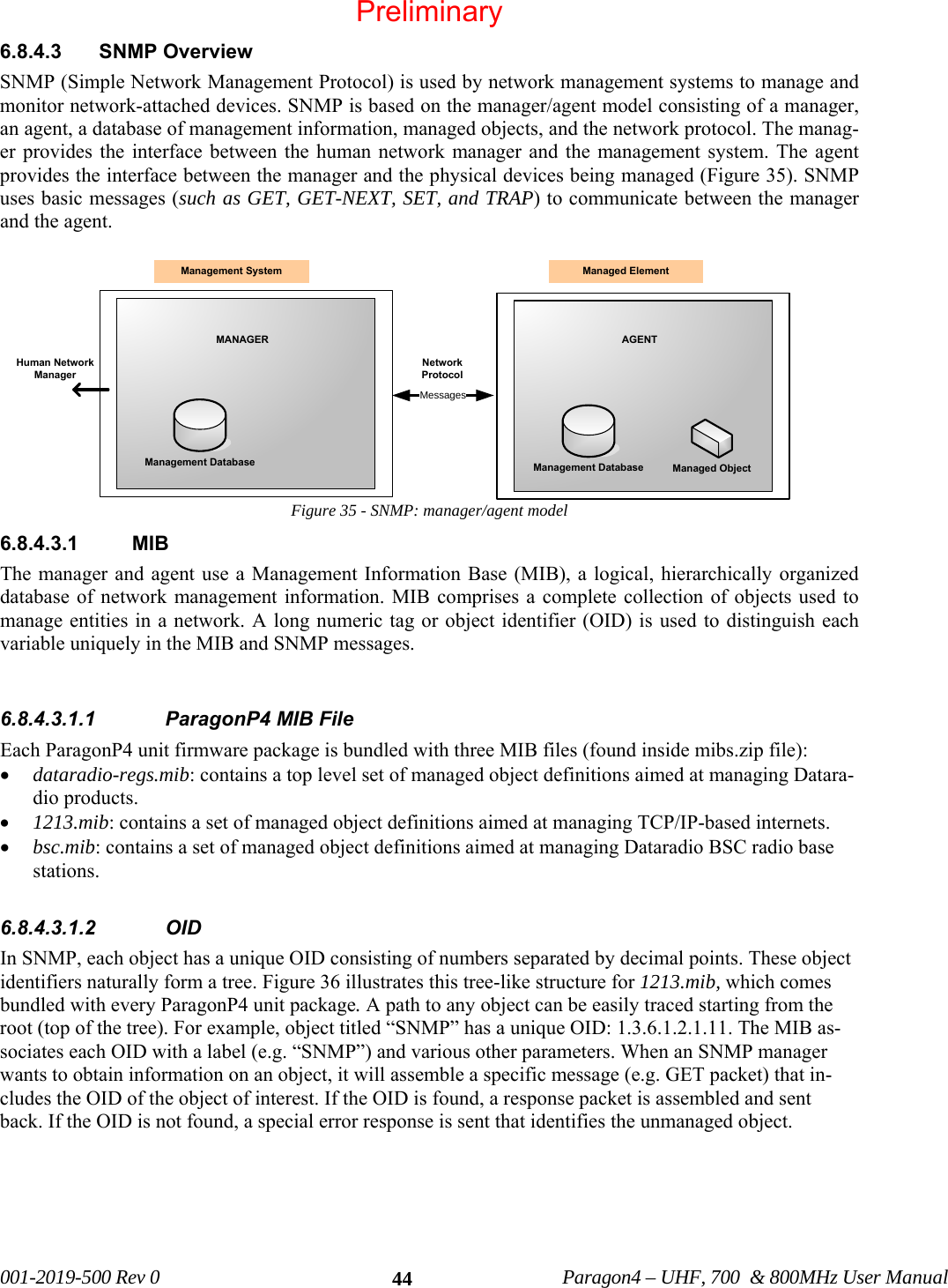
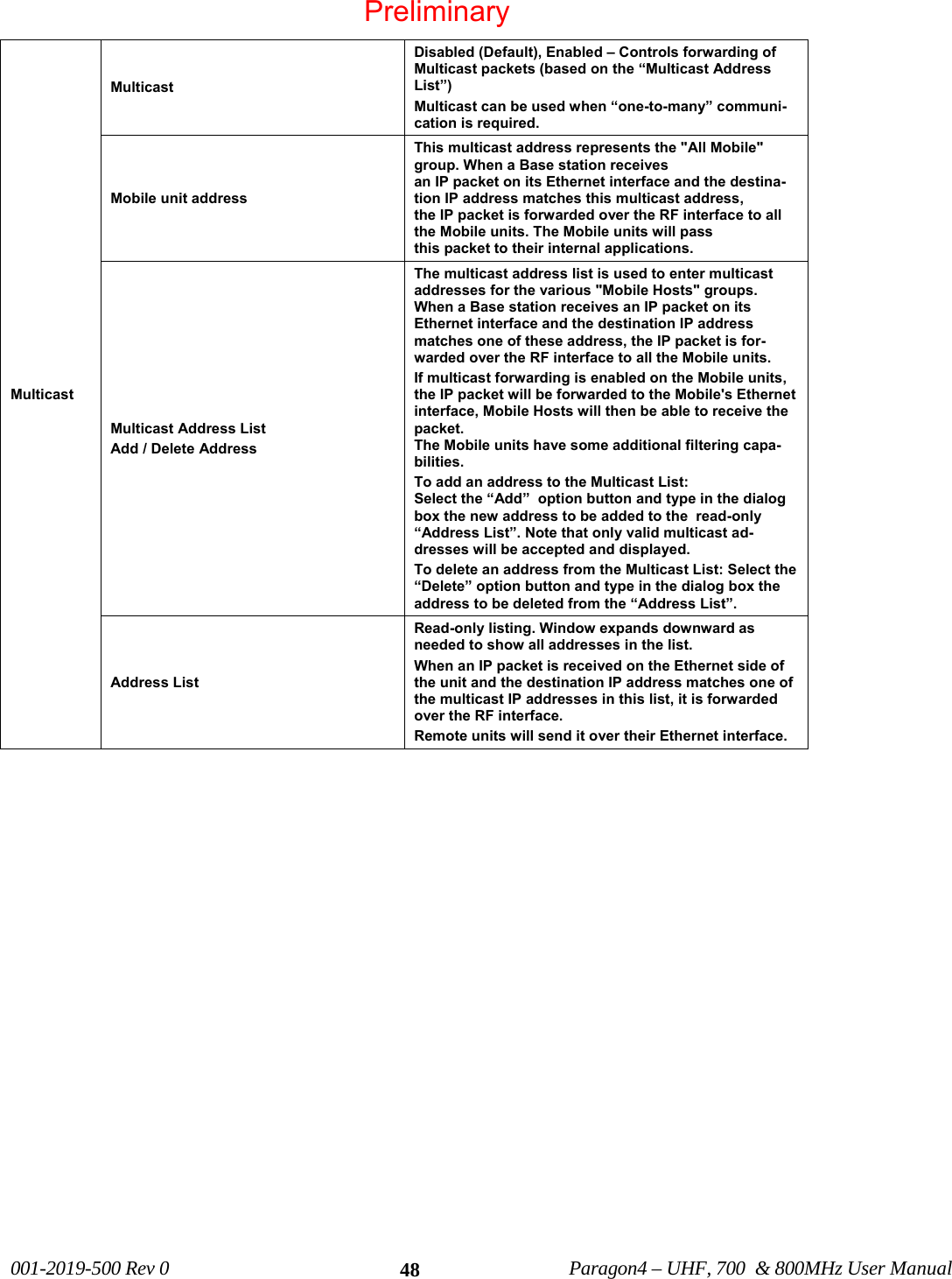
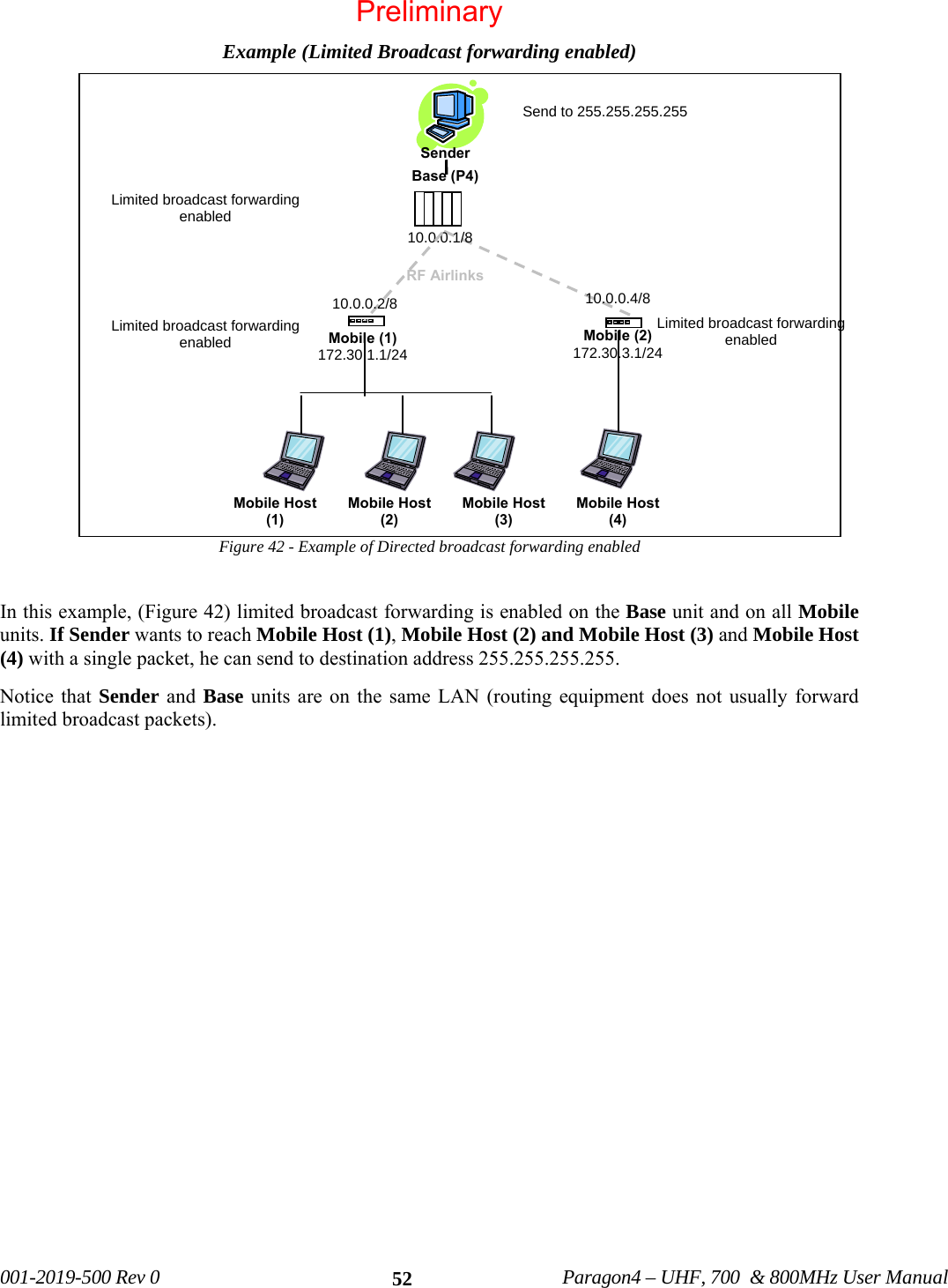
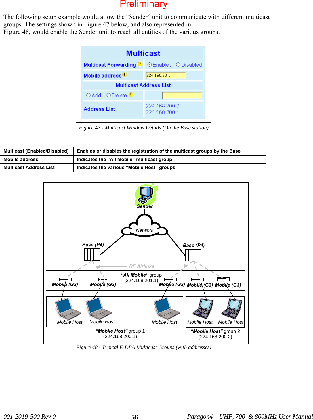
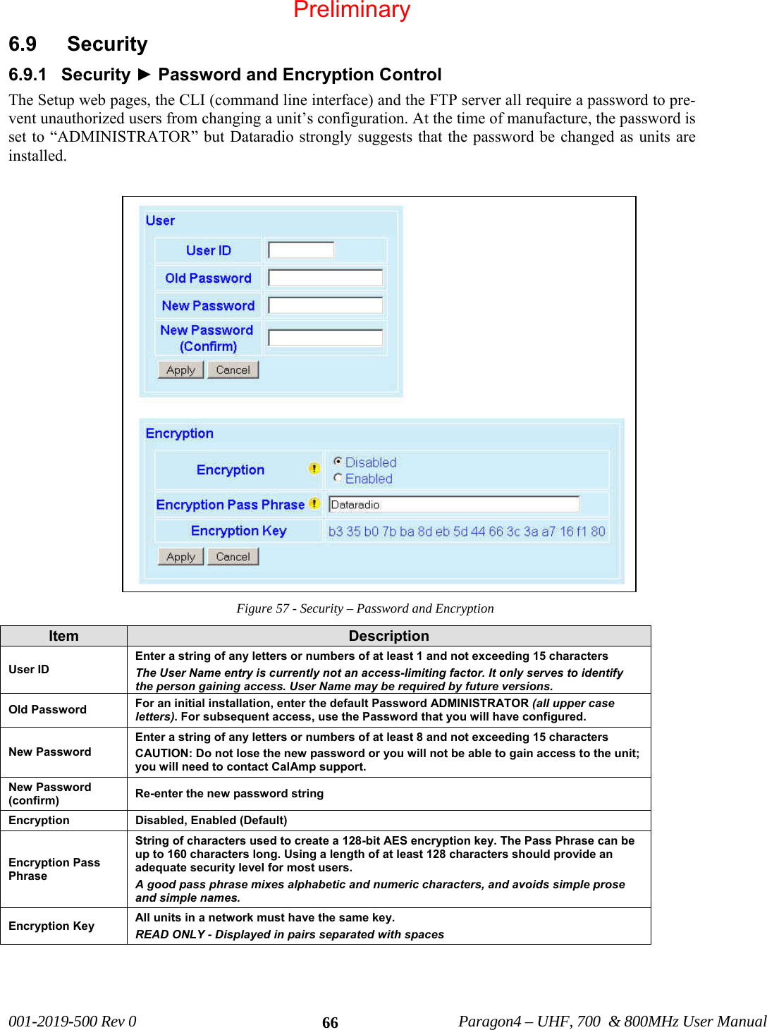
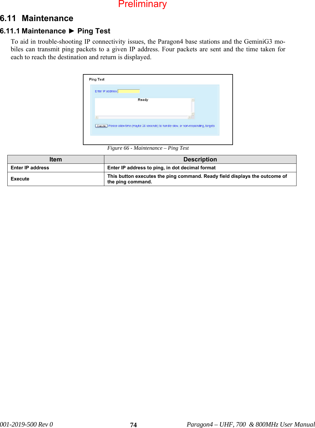
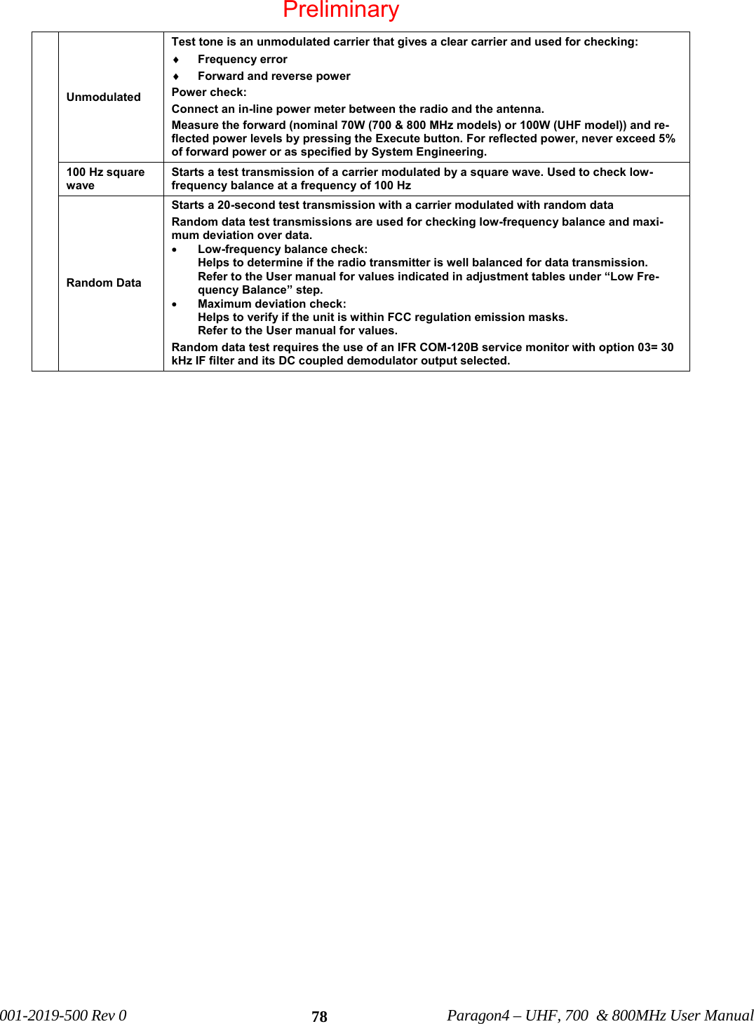
![001-2019-500 Rev 0 Paragon4 – UHF, 700 & 800MHz User Manual 98 EMISSION DESIGNATORS Bit rate Baud rate Modulation UHF 700MHz 800MHz 128000 32000 SRRC16FSK - 27K0F1D (pending) - 96000 32000 SRRC8FSK - 27K0F1D (pending) - 64000 32000 SRRC4FSK - 27K0F1D (pending) - 64000 16000 SRRC16FSK 16K1F1D (C) 14K0F1D (pending) 13K7F1D (G) 48000 16000 SRRC8FSK 15K8F1D (C) 14K0F1D (pending) 13K7F1D (G) 43200 14400 SRRC8FSK 15K8F1D (C) 14K8F1D (pending) 13K4F1D (G) 32000 16000 SRRC4FSK 16K1F1D (C) 14K0F1D (pending) 13K4F1D (G) 32000 8000 SRRC16FSK 8K30F1D (D) 7K20F1D (pending) 10K0F1D (H) 8K2F1D (D) 24000 8000 SRRC8FSK 8K30F1D (D) 7K20F1D (pending) 10K0F1D (H) 8K2F1D (D) 16000 8000 SRRC4FSK 7K80F1D (D) 7K20F1D (pending) 10K0F1D (H) 8K2F1D (D) [1] FCC/IC mask G (800MHz, 25kHz ch.) [2] FCC mask H (800MHz, NPSPAC ch.) [3] IC mask D (800MHz, 12.5kHz ch.) [4] FCC/IC mask C (UHF, 25kHz ch.) [5] FCC/IC mask D (UHF, 12.5kHz ch.) Preliminary](https://usermanual.wiki/CalAmp-Wireless-Network/BDP4-EXCT438/User-Guide-1290807-Page-106.png)