CalAmp Wireless Networks 1409123000 2.5 GHz Wireless Broadband Route User Manual SECTION 1 PREFACE
CALAMP WIRELESS NETWORKS INC. 2.5 GHz Wireless Broadband Route SECTION 1 PREFACE
User Manual
C
Ca
al
lA
Am
mp
p
S
Se
en
nt
tr
ry
y
4
4G
G
2
25
50
00
0T
TM
M
2.5 G H Z
802.16- 2 0 0 5 S U B S C R I B E R S T A T I O N B R O A D B A N D R O U T E R
U s e r M a n u a l
P / N 0 0 1 - 9 1 2 3 - 001
V e r s i o n 1
F e b r u a r y 2 0 1 1

TABLE OF CONTENTS
001-9193-001 Version 3 Page 3 of 52 Sentry 4G TM User
Manual
1. PREFACE .......................................................................................................................................................................... 5
1.1 COPYRIGHT NOTICE ................................................................................................................................................................ 5
1.2 ROUTER USE ......................................................................................................................................................................... 5
1.3 INTERFERENCE ISSUES ............................................................................................................................................................. 5
1.4 MOBILE APPLICATION SAFETY ................................................................................................................................................... 6
1.5 FCC NOTIFICATION................................................................................................................................................................. 6
2. PRODUCT OVERVIEW ....................................................................................................................................................... 7
2.1 GENERAL DESCRIPTION............................................................................................................................................................ 7
2.2 FEATURES ............................................................................................................................................................................. 7
2.3 EXTERNAL INTERFACES ............................................................................................................................................................ 8
2.4 RJ-45 ETHERNET PORT INTEGRATION PARAMETERS ...................................................................................................................... 9
2.5 POWER CABLE CONNECTIONS ................................................................................................................................................... 9
2.6 ANTENNA OPTIONS .............................................................................................................................................................. 11
3. NETWORKING BASICS .................................................................................................................................................... 13
3.1 GENERAL NETWORKING DEFINITIONS ....................................................................................................................................... 13
4. GETTING STARTED ......................................................................................................................................................... 15
4.1 PACKAGE CONTENTS ............................................................................................................................................................. 15
4.2 SETUP REQUIREMENTS .......................................................................................................................................................... 15
4.3 QUICK START....................................................................................................................................................................... 15
4.4 CONFIGURING LOCAL PC ....................................................................................................................................................... 16
4.5 SENTRY 4G ROUTER SETUP .................................................................................................................................................... 17
5. SENTRY 4G CONFIGURATION ......................................................................................................................................... 19
5.1 GENERAL INSTRUCTIONS ........................................................................................................................................................ 19
5.2 HOME PAGE PARAMETERS ..................................................................................................................................................... 19
5.3 WWAN PARAMETERS .......................................................................................................................................................... 21
5.4 LAN SETTINGS (ETH0 AND ETH1) ......................................................................................................................................... 27
5.5 WIFI (WLAN) .................................................................................................................................................................... 29
5.6 ROUTER SETTINGS ................................................................................................................................................................ 36
5.7 GENERAL SETTINGS............................................................................................................................................................... 40
5.8 GPS STATUS AND SETTINGS ................................................................................................................................................... 42
5.9 I/O SETTINGS ...................................................................................................................................................................... 45
5.10 SYSTEM UPGRADE (OPTIONAL SERVICE) ................................................................................................................................. 49
6. SPECIFICATIONS ............................................................................................................................................................. 50
7. ABBREVIATIONS ............................................................................................................................................................ 51
8. SERVICE AND SUPPORT .................................................................................................................................................. 52
8.1 PRODUCT WARRANTY, RMA AND CONTACT INFORMATION ........................................................................................... 52
8.2 RMA REQUEST ................................................................................................................................................................. 52
8.3 PRODUCT DOCUMENTATION .......................................................................................................................................... 52
8.4 TECHNICAL SUPPORT ....................................................................................................................................................... 52
FIGURE 1 – SENTRY 4G ROUTER FRONT PANEL ...................................................................................................................................... 8
FIGURE 2 – SENTRY 4G POWER CABLE CONNECTIONS ........................................................................................................................... 10
FIGURE 3 – SENTRY 4G ROUTER SETUP EQUIPMENT .............................................................................................................................. 15
FIGURE 4 - LOCAL AREA CONNECTION PROPERTIES (WINDOWS XP) ......................................................................................................... 16

TABLE OF CONTENTS
001-9193-001 Version 3 Page 4 of 52 Sentry 4G TM User
Manual
FIGURE 5 - INTERNET PROTOCOL (TCP/IP PROPERTIES) ......................................................................................................................... 17
FIGURE 6 – SENTRY 4G ROUTER HOMEPAGE ....................................................................................................................................... 18
FIGURE 7 – SENTRY 4G ROUTER UNIT STATUS ..................................................................................................................................... 20
FIGURE 8 – SENTRY 4G ROUTER WWAN SETTINGS .............................................................................................................................. 23
FIGURE 9 – SENTRY 4G WWAN CHANNEL SELECTION .......................................................................................................................... 24
FIGURE 10 – SENTRY 4G ROUTER WWAN STATUS .............................................................................................................................. 25
FIGURE 11 - IP SETTINGS ................................................................................................................................................................. 27
FIGURE 12 - SENTRY 4G ROUTER WIFI MODES: ACCESS POINT (A); CLIENT MODE (B) ............................................................................... 30
FIGURE 13 - WIFI (WLAN)WIRELESS SETTINGS (CLIENT) .................................................................................................................. 31
FIGURE 14 - WIFI (WLAN) WIRELESS SETTINGS (ACCESS POINT) ........................................................................................................ 33
FIGURE 15 - WIFI (WLAN) STATISTICS........................................................................................................................................... 35
FIGURE 16 - WIFI (WLAN) WIRELESS SETTINGS (SITE SURVEY) .......................................................................................................... 35
FIGURE 17 - STATIC ROUTES ............................................................................................................................................................. 36
FIGURE 18 - IP FILTERING ................................................................................................................................................................ 38
FIGURE 19 - PORT FORWARDING ....................................................................................................................................................... 39
FIGURE 20 - ROUTING TABLE ............................................................................................................................................................ 39
FIGURE 21 - INTERFACE PRIORITY ...................................................................................................................................................... 40
FIGURE 22 - REMOTE ADMIN ............................................................................................................................................................ 40
FIGURE 23 - EXAMPLE OF REMOTE LOGIN ........................................................................................................................................... 41
FIGURE 24 - POWER MANAGEMENT .................................................................................................................................................. 41
FIGURE 25 - GPS STATUS ................................................................................................................................................................ 42
FIGURE 26 - AAVL SETTINGS ............................................................................................................................................................ 43
FIGURE 27 - I/O SETTINGS-STATUS .................................................................................................................................................... 46
FIGURE 28 - I/O SETTINGS ............................................................................................................................................................... 47
FIGURE 29 - I/O SETTINGS-LABELS .................................................................................................................................................... 47
FIGURE 30 - SENTRY 4G UPGRADE .................................................................................................................................................... 49
TABLE 1 - LED DEFINITIONS................................................................................................................................................................ 8
TABLE 2 - STANDARD RJ-45 ETHERNET PIN-OUTS ................................................................................................................................... 9
TABLE 3 - POWER SUPPLY CONNECTIONS ............................................................................................................................................. 10
TABLE 4 - ENCRYPTION KEYS EXAMPLES .............................................................................................................................................. 32
TABLE 5 - I/O SIGNAL PINOUT .......................................................................................................................................................... 45

PREFACE
001-9193-001 Version 2 Page 5 of 52 Sentry 4G TM User
Manual
1. PREFACE
1.1 Copyright Notice
©2011 CalAmp Corp. All Rights Reserved.
This manual covers the operation of the Sentry4G 2500 router. Specifications described are
typical only and are subject to normal manufacturing and service tolerances.
CalAmp reserves the right to modify the equipment, its specifications or this manual without
prior notice, in the interest of improving performance, reliability, or servicing. At the time of
publication all data is correct for the operation of the equipment at the voltage and/or
temperature referred to. Performance data indicates typical values related to the particular
product.
No part of this documentation or information supplied may be divulged to any third party
without the express written consent of CalAmp Corp.
Products offered may contain software which is proprietary to CalAmp Corp. The offer or
supply of these products and services does not include or infer any transfer of ownership.
1.2 Router Use
The Sentry 4G 2500TM is designed and intended for use in fixed, nomadic, or mobile
applications. “Fixed” assumes the device is physically secured at one location and not easily
moved to another location.” Nomadic” assumes the unit is installed in a vehicle but is
operated when the vehicle is stationary. “Mobile” assumes the unit is physically secured in a
vehicle and is operated when the vehicle is moving. The Sentry 4G router supports full
mobility.
1.3 Interference Issues
Avoid possible radio frequency (RF) interference by following these guidelines:
Do not operate in the vicinity of gasoline or diesel-fuel pumps unless use has been
approved and authorized.
Do not operate in locations where medical equipment that the device could interfere
with may be in use.
Do not operate in fuel depots, chemical plants, or blasting areas unless use has been
approved and authorized.
Use care if operating in the vicinity of protected personal medical devices, i.e.,
hearing aids and pacemakers.
Operation in the presence of other electronic equipment may cause interference if
equipment is incorrectly protected. Follow recommendations for installation from
equipment manufacturers.

PREFACE
001-9193-001 Version 2 Page 6 of 52 Sentry 4G TM User
Manual
1.4 Mobile Application Safety
Road safety is crucial. Do not change parameters or perform other maintenance of
the Sentry 4G while driving.
Avoid potential interference with vehicle electronics by correctly installing the Sentry
4G router. CalAmp Corp recommends installation by a professional.
1.5 FCC Notification
This device complies with part 27 of the FCC rules.
Changes or modifications not expressly approved by the party responsible for compliance could
void the user's authority to operate the equipment.
Note: This equipment generates, uses, and can radiate radio frequency energy and, if not installed
and used in accordance with the instructions, may cause harmful interference to radio
communications. However, there is no guarantee that interference will not occur in a particular
installation. If this equipment does cause harmful interference to radio or television reception,
which can be determined by turning the equipment off and on, the user is encouraged to try to
correct the interference by one or more of the following measures:
Reorient or relocate the receiving antenna.
Increase the separation between the equipment and receiver.
Connect the equipment into an outlet on a circuit different from that to which the
receiver is connected.
Consult the dealer or an experienced radio/TV technician for help.
Caution pertaining to the 4G output terminals:
This device is subject to different restrictions whether it is operated as a mobile terminal or as a
fixed station. When this device is operated as mobile subscriber equipment, the peak equivalent
isotropically radiated power (EIRP) shall not exceed 2 watts. As the default maximum conducted
output power of the device is near the allowed 2 Watts, it is required that this maximum power be
reduced by a ratio corresponding to the gain of the antenna used. For example if the 4G antennas
installed have a 5 dBi gain, the output power shall be reduced by the equivalent 5 dB, making the
conducted maximum output power 0.63 Watt at the most.
When the device is operated as a fixed station, the antenna gain shall be such that the EIRP is
limited to 40 Watts.
This configuration shall be executed by a professional installer.

PRODUCT OVERVIEW
001-9193-001 Version 2 Page 7 of 52 Sentry 4G TM User Manual
2. PRODUCT OVERVIEW
2.1 General Description
The Sentry 4G 2500TM from CalAmp provides high-speed, long-range 802.16-2005 compliant
connectivity in the licensed 2.5 GHz band. Based on industrial grade IEEE 802.16-2005
technology, it features extensive routing capabilities with an easy-to-use interface and
comprehensive remote management. Built-in GPS, two Ethernet ports, an optional 802.11b/g
access point and a 3G module allows connectivity in the office or on the road.
Ensuring the protection of even the most sensitive data, Sentry 4G combines built-in
standard 802.16-2005 encryption services such as TKIP/AES and EAP-TTLS supplicant. Not
only versatile and secure, its rugged enclosure withstands even the harshest conditions with
an extended temperature range.
2.2 Features
4G Subscriber station broadband router based on IEEE 802.16-2005 technology
Secure data access with 802.16-2005 encryption services such as TKIP/AES
Fast handover for real time applications with no service degradation
Superior RF performance with MIMO capabilities
AVL support through integrated GPS with local remote NMEA data
Optional integrated 802.11 b/g local wireless connectivity (WiFi IEEE 802.11b/g 2.4GHz)
Optional 3G cellular carrier module (EVDO Rev A with backward compatibility to EVDO Rev 0
and CDMA 1xRTT.
Built-in WiFi client and access point
Embedded Linux (with support for custom applications) on PowerPC processor
Built-in DHCP server and NAT support
Browser-based management
Local and remote configuration
Two (2) 10/100 Ethernet interfaces
I/O capability
PRODUCT OVERVIEW
001-9193-001 Version 2 Page 8 of 52 Sentry 4G TM User Manual
2.3 External Interfaces
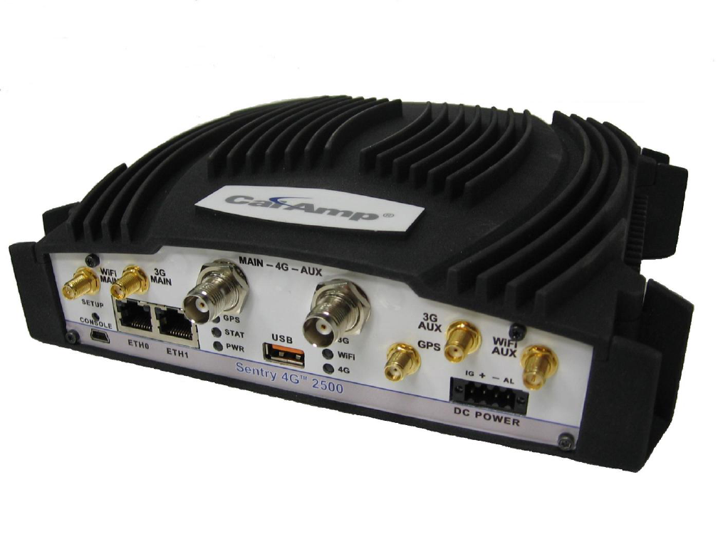
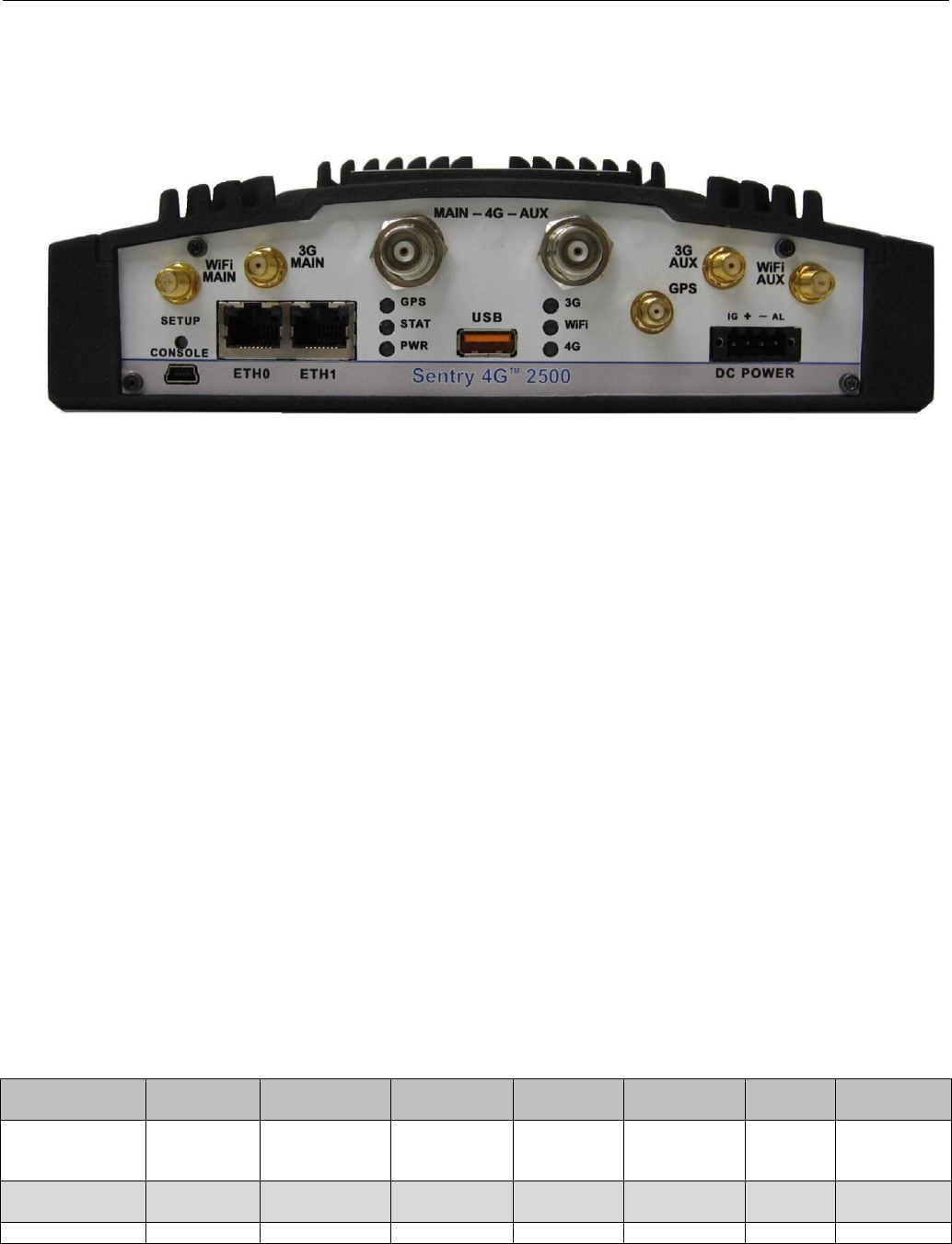
2.3.1 Front Panel Connections
Figure 1 – Sentry 4G Router Front Panel
Sentry 4G front panel connections include:
TRX: Two TNC female, Transmit/Receive antenna connections. See section 2.6 “Antenna
options” for more information.
WiFi: RP-SMA jack, WiFi antenna. See section 2.6 “Antenna options” for more information.
3G: SMA jack, cellular antenna. See section 2.6 “Antenna options” for more information.
ETH0 and ETH1: Inputs for standard or crossover Ethernet cable
GPS: SMA female, GPS antenna connector. This input requires a 3.3V, GPS antenna with an
SMA connection. For best coverage, use an active GPS antenna with a gain between 10 and
30 dB.
USB: USB A Female connector. Reserved for future use.
Console: 3-wire serial in a USB Mini B female form factor (requires a custom USB Mini B to
EIA-232-F DB9 cable) for debugging and maintenance only.
PWR: 10-30 VDC; the mating connector is a Weidmuller 1615800000 connector.
2.3.2 LEDs
There are nine LEDs on the front panel of the Sentry 4G unit. Each (except the Ethernet
LEDs) can display three colors: Red, Green, and Amber. The definition for each LED is as
follows:
Table 1 - LED Definitions
INDICATOR
OFF
SOLID
GREEN
FLASHING
GREEN
SOLID
AMBER
FLASHING
AMBER
SOLID
RED
FLASHING
RED
PWR
(Power)
No Power
Power on
App.Running
Test Mode
Hardware
Power up
Sequence
Software
boot
sequence
Power
Supply
Fault
N/A
STAT (Status)
No Power
Status
Normal
N/A
Warning
Factory
Defaults
Fault
N/A
GPS
GPS
Position Fix
1PPS
No
Acquiring
Fault
N/A
PRODUCT OVERVIEW
001-9193-001 Version 2 Page 9 of 52 Sentry 4G TM User Manual
Disabled
Acquired
Activity
Satellites
in View
Satellites
3G (WWAN)
I/F
Disabled
Connected
RX/TX
Activity
Failed to
establish
connection
Establishing
Connection
Fault
N/A
4G (WWAN)
I/F
Disabled
Connected
RX/TX
Activity
Failed to
establish
connection
Establishing
Connection
Fault
N/A
WiFi (client)
N/A
Connected
RX/TX
Activity
Failed to
establish
connection
Establishing
Connection
Fault
N/A
WiFi (Access
Point)
IF/Disabled
Ready
RX/TX
Activity
N/A
N/A
Fault
N/A
ETH0
No link
100mbps
link
RX/TX
Activity
10 mbps
link
N/A
N/A
N/A
ETH1
No activity
N/A
RX/TX
Activity
N/A
N/A
N/A
N/A
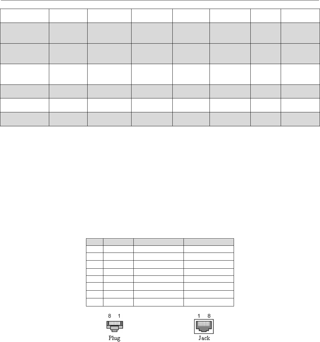
2.4 RJ-45 Ethernet Port Integration Parameters
Table 2 below provides the information to purchase Ethernet cables to integrate the Sentry
4G product into your system.
Note:
The Sentry 4G unit can accept either a standard or cross over Ethernet cable. A standard
Ethernet cable is one that has matching pin assignments on both ends (T568A or T568B),
while a cross over Ethernet cable is one that has a T568A termination on one end and
T568B on the other.
Table 2 - Standard RJ-45 Ethernet Pin-outs
Pin
Function
T568A
T568B
1
TX +
White/Green
White/Orange
2
TX -
Solid Green
Solid Orange
3
RX +
White/Orange
White/Green
4
Solid Blue
Solid Blue
5
White/Blue
White/Blue
6
RX -
Solid Orange
Solid Green
7
White/Brown
White/Brown
8
Solid Brown
Solid Brown
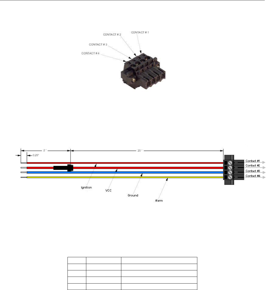
2.5 Power Cable Connections
If using the provided power cable to connect to a DC supply (car battery) use the following
diagrams and table to connect the unit.
PRODUCT OVERVIEW
001-9193-001 Version 2 Page 10 of 52 Sentry 4G TM User
Manual
Note: Both ignition sense and DC power are required to start up a Sentry 4G unit.
Figure 2 – Sentry 4G Power Cable Connections
Table 3 - Power supply connections
Pin
Color
Description
1
Thin Red
Ignition Sense
2
Red
DC Power, 10 to 30V DC
3
Blue
Ground
4
Yellow
Officer down alarm
If connection to an AC supply is desired, an AC/12VDC power supply and cable are available.

PRODUCT OVERVIEW
001-9193-001 Version 2 Page 11 of 52 Sentry 4G TM User
Manual
2.6 Antenna Options
Antennas are available for Sentry 4G routers installations from CalAmp Corp.
2.6.1 4G Transmit/Receive Antennas (MAIN-AUX)
The primary antenna connections on the Sentry 4G unit are TNC female connectors; therefore
you must purchase antennas with TNC male connectors. Do not select TNC antennas with
“reverse polarity” or RP-Male. Mounting options and cable lengths are the user’s choice and
application specific.
Recommended antenna:
Manufacturer
Model Number
Antenna Type
Gain
PCTEL
BMAXC233805
Perm. Mount
5 dBi
If the Sentry unit is operated as a mobile terminal, the output power shall be reduced by a ratio
corresponding to the antenna gain. For instance, if the recommended antenna is used, the gain
shall be reduced by 5 dB. The antenna installation must be done by a professional.
2.6.2 GPS Antenna
The Sentry 4G router’s GPS connector requires an external 3.3V GPS antenna. The GPS antenna
connection on the Sentry 4G product is a female SMA connector; therefore an antenna with an
SMA male connector is required. For best coverage, use an active antenna with a gain between
10 and 30 dB. Mounting options and cable lengths are user’s choice and application specific.
Recommended Antenna:
2.6.3 WiFi Antennas
The WiFi antenna connections on the Sentry 4G product are RP-SMA jacks; therefore antennas
with an RP-SMA plug are required. Mounting options and cable lengths are user’s choice and
application specific.
Industry Canada RSS Notices:
This device has been designed to operate with the antennas listed below, and having a
maximum gain of 5.5 dBi. Antennas not included in this list or having a gain greater than 5.5
dBi are strictly prohibited for use with this device. The required antenna impedance is 50Ω.
Manufacturer
Model Number
Antenna Type
Gain
PCTEL
BMMG24005ML195RPMSMA
Mag. Mount
5 dBi
To reduce potential radio interference to other users, the antenna type and its gain should be
so chosen that the equivalent isotropically radiated power (EIRP) is not more than that
permitted for successful communication.
Manufacturer
Model Number
Antenna type
Gain
PCTEL
AGPSPH16MM
Mag. Mount
4 dBiC

PRODUCT OVERVIEW
001-9193-001 Version 2 Page 12 of 52 Sentry 4G TM User
Manual
2.6.4 3G Antennas
The cellular (3G) antenna connections on the Sentry 4G product are SMA female jacks;
therefore, antennas with an SMA male connector are required. Mounting options and cable
lengths are user’s choice and application specific.
Recommended Antenna:
2.6.5 Antenna Spacing
For proper operation and rule compliance, it is requested that all antennas be installed in such a fashion
that any antenna be at least 20 cm from the closest neighboring antenna. This requirement holds for
WiMAX, 3G, WiFi and GPS antennas.
Manufacturer
Model Number
Antenna type
Gain
PCTEL
ASPRDM1994S
Mag. Mount
3 dBd

NETWORKING BASICS
001-9193-001 Version 2 Page 13 of 52 Sentry 4G TM User
Manual
3. Networking basics
3.1 General Networking Definitions
The Sentry 4G router is based on Ethernet connectivity and follows general IP networking
guidelines and terminology. Below are definitions of some basic network terminology as they
pertain to the Sentry 4G environment.
Term
Definition
BTS
Base Transceiver Station, fixed equipment that incorporates all radio-
intelligence functions controlling the 802.16-2005 link with one or more Sentry
4G routers.
CINR
Carrier to Interference-plus-Noise Ratio, expressed in decibels (dBs), is a
measurement of signal effectiveness. It provides information on how strong the
desired signal is compared to the unwanted energy (interference plus noise).
DNS
Domain Name System: operates like a phone book to translate domain names
(i.e., google.com) to IP addresses (70.212.19.1).
The Sentry 4G unit functions as the DNS Server in the network.
DHCP
Dynamic Host Configuration Protocol: the DHCP server assigns IP addresses,
gateway and subnet masks to all clients on the network.
The Sentry 4G unit functions as a DHCP Server.
Dynamic/Static IP
A device with Dynamic IP selected may have a different IP address every time
it connects to the network. A device with a Static IP will always connect with
the same IP address.
EAP-TTLS
(Extensible
Authentication
Protocol-Tunneled
Transport Layer
Security)
A universal authentication framework frequently used in wireless networks and
Point-to-Point connections. EAP-TTLS is an EAP method that encapsulates a
TLS session, consisting of a handshake phase and a data phase. During the
handshake phase, the server is authenticated to the client using standard TLS
procedures, and keying material is generated in order to create a
cryptographically secure tunnel for information exchange in the subsequent
data phase. During the data phase, the client is authenticated to the server
using an arbitrary authentication mechanism encapsulated within the secure
tunnel.
Gateway
A (node) device enabling data transfer between different networks (i.e., from a
private LAN to a public WAN).
LAN
Local Area Network. A private network.
MIMO
Multiple Input Multiple Output. MIMO algorithms send information out over two
or more antennas; the information is received via multiple antennas as well.
This use of multiple antennas at both the transmitter and receiver provides a
significant capacity gain over conventional single antenna systems and/or
a more reliable communication.
NAT
Network Address Translation: A technology that allows hosts on the LAN with
private IP addresses to communicate with public IP addresses on the WAN.
This is an essential function of a network router.
OFDM
Orthogonal Frequency Division Multiplexing. 802.16-2005 being a wide area
network is very sensitive to interference and multi-path fading. OFDM
addresses these problems by partitioning the data stream into multiple
narrowband transmissions in the frequency domain using subcarriers that are
orthogonal to one another (do not interfere). These subcarriers are then
reassembled for over-the-air retransmission.
OFDMA
Orthogonal Frequency Division Multiple Access. Allows OFDM to serve many
terminals. Each terminal will be assigned a subset of the subcarrier set for a

NETWORKING BASICS
001-9193-001 Version 2 Page 14 of 52 Sentry 4G TM User
Manual
given time interval.
Port
A special number present in the header of a data packet in the data transfer
process. Ports are typically used to map data to a particular process running on
a computer.
PPP
Point-to-point Protocol: creating a direct link between two nodes in network
communication.
Private IP address
Private IP addresses are addresses that will not be routed on external
networks. Any device on an internal LAN should be assigned a private IP
address to avoid contention. The suggested private address ranges are
Class A: 10.x.x.x
Class B: 172.16.x.x through 172.31.x.x
Class C: 192.168.x.x
By default the Sentry 4G unit uses the 192.168.1.x address range.
RIP
Routing Information Protocol, protocol that helps routers dynamically adapt to
changes of network connections by communicating information about which
networks each router can reach and how far away those networks are.
SOFDMA
Scalable OFDMA. With bandwidth scalability, Mobile 802.16-2005 technology
can comply with various channel assignments.
SSID
Service Set Identifier. This is a name used to identify a WiFi wireless network.
Subnet
A range of addresses assigned to a LAN.
All devices connected in a Sentry 4G network must be on the same subnet as
the Sentry 4G routers.
Subnet Mask
Binary string that separates the subnet portion of an IP address and the host
portion.
TKIP/AES
“Temporal Key Integrity Protocol” is an encryption method used by the WiFi
interface when operating in WPA mode. TKIP was designed to solve security
issues in WEP (it is considered stronger then WEP).
"Advanced Encryption Standard" is the encryption protocol used by the WiFi
interface when it operates in WPA2 mode.
WAN
Wide Area Network, a public network. The Internet is an example of a WAN.
WEP
Wired Equivalent Privacy. This is an IEEE security protocol for wireless 802.11
networks. It is an encryption method used by the WiFi interface.
WiFi
(802.11b,
802.11g)
Wireless Fidelity is an IEEE 802.11 standard for wireless LANs
802.11b is a standard for operating at 2.4 GHz frequency with data rates up
to 11 Mbps
802.11g is a standard for operating at 2.4 GHz frequency with data rates up
to 54 Mbps
WiFi Access Point
(802.11)
A Sentry 4G unit can operate in 802.11 access point mode. It can
communicate with other devices operating in 802.11 access point mode.
WiFi Client (802.11
Infrastructure
mode)
A Sentry 4G unit can operate in 802.11 Infrastructure mode. In this mode it is
a WiFi client and will try to connect to a WiFi access point.
WLAN
Wireless Local Area Network, a private network. Refers to the network covered
by the WiFi interface.
WPA/WPA2
WiFi Protected Access" is a subset of 802.11i (security mechanisms for wireless
networks).
"WiFi Protected Access 2" is the complete version of 802.11i.

GETTING STARTED
001-9193-001 Version 2 Page 15 of 52 Sentry 4G TM User
Manual
4. GETTING STARTED
4.1 Package Contents
Sentry 4G router
Quick Start Guide
Power cable
User Manual and Quick Start Guide on CD
Mounting Screws
4.2 Setup Requirements
Sentry 4G router
Computer running any operating system with a web browser installed such as Microsoft
Internet Explorer version 6.0 or later or Firefox version 2.0 or later.
10-30V 5-A power supply
Ethernet cable*
Two antennas with male TNC connector*
GPS Antenna (SMA Male) *
Two WiFi Antennas (RP-SMA Plug) * ( if applicable)
Two cellular (3G) antennas (SMA Plug) * (if applicable)
*These accessories are available from CalAmp.
4.3 Quick Start
4.3.1 Hardware Setup
Figure 3 – Sentry 4G router setup equipment
1. Connect the two Transmit/Receive antennas to the 4G MAIN and AUX TNC connectors on the
front of the unit. Connect the GPS antenna to the GPS connector. For units utilizing WiFi,
connect the WiFi antennas to the WiFi connectors. For units utilizing 3G, connect the 3G
antennas to the 3G connectors.
2. Connect an Ethernet cable from the ETH0 connector of the Sentry 4G unit to the PC. If
multiple PCs are being used, connect the Sentry 4G unit to an Ethernet switch or hub
connected to the PCs.
3. Connect a power supply cable to the PWR connector of the Sentry 4G unit. Do not power the
unit on yet.
GETTING STARTED
001-9193-001 Version 2 Page 16 of 52 Sentry 4G TM User
Manual
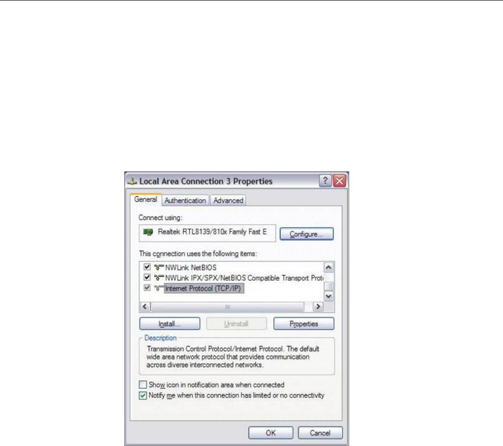
4.4 Configuring Local PC
1. Verify network settings on local PC are set to automatically detect IP and DNS server. The
path to network settings varies with the version of Windows you are using.
Windows XP: Start-> Control Panel -> Network Connections
Windows 2000: Start -> Settings -> Network and dial up connections
2. Select the appropriate network connection, typically the Local Area Connection -> right click
on the connection and select “Properties”
3. Select “Internet Protocol (TCP/IP) properties.
Figure 4 - Local Area Connection Properties (Windows XP)
4. Verify that “Obtain an IP address automatically” and “Obtain DNS Server address
automatically” are selected.
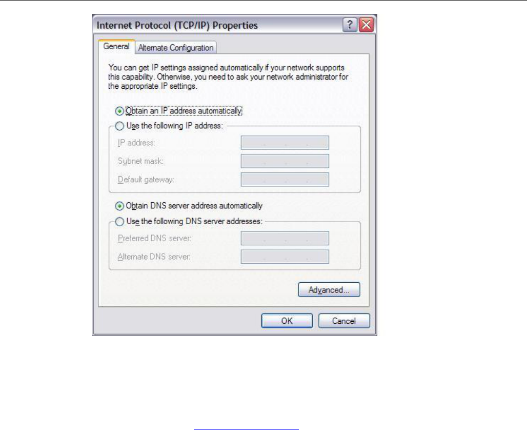
GETTING STARTED
001-9193-001 Version 2 Page 17 of 52 Sentry 4G TM User
Manual
Figure 5 - Internet Protocol (TCP/IP Properties)
4.5 Sentry 4G Router Setup
1. Power on the Sentry 4G router with 10-30VDC power supply.
2. In an Internet browser, enter http://192.168.1.50. This will bring up the Sentry 4G product
login page (Note: It may take 30 seconds from initial power-up for the homepage to be
available.)
3. Login to the device
Default Login values
User logon: admin
password: password
4. This brings up the Sentry 4G product homepage. You can view status and configuration
parameters from this screen. The configuration options are further explained later in this
document.
GETTING STARTED
001-9193-001 Version 2 Page 18 of 52 Sentry 4G TM User
Manual
Figure 6 – Sentry 4G Router Homepage

CONFIGURATION
001-9193-001 Version 2 Page 19 of 52 Sentry 4G TM User
Manual
5. Sentry 4G Configuration
This section explains status information and configuration options available on all HTML pages.
5.1 General Instructions
The following instructions are common to all HTML pages
The Help, Home and Reset links are located at the top right of all HTML pages.
Help: Select this link on any of the devices configuration pages to bring up the help text for
that screen.
Home: Select this link to return to the home page of the router.
Reset: Select this link to command the unit to reboot. This process will take about 40
seconds. The software will ask you to confirm this command prior to re-booting.
Save: Most changes to a configuration parameter require the user to click save before the
change will take effect.
Clear/Cancel: Most configuration menus also have a “Clear/Cancel” option. Selecting this
button will restore all fields in a section to their last saved value. Note: This does not return them
to their factory defaults.
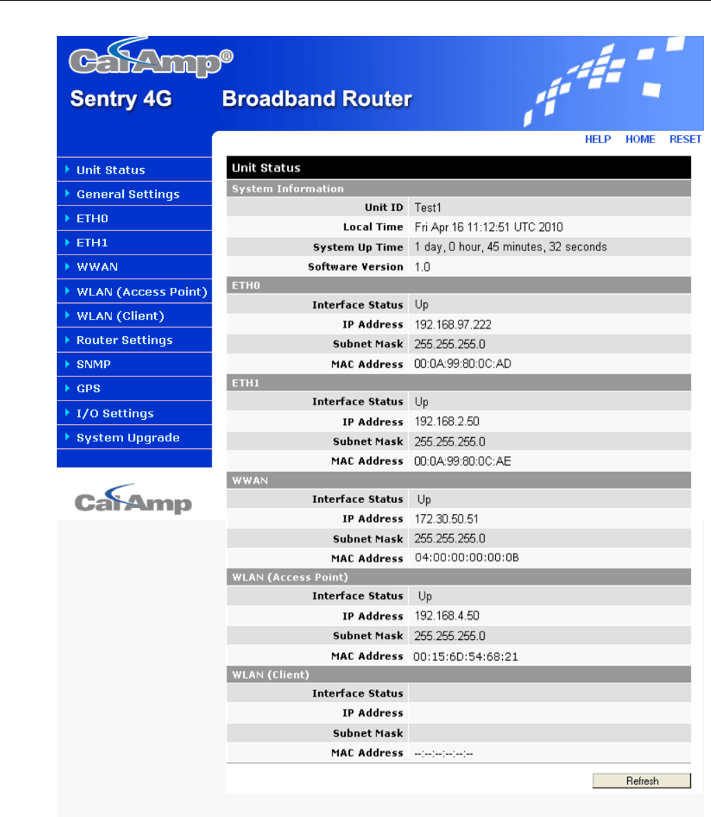
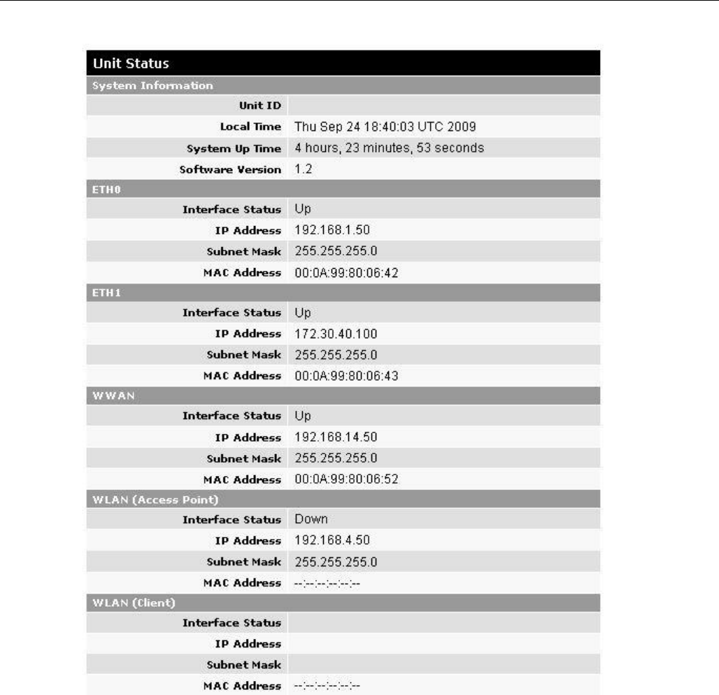
5.2 Home Page Parameters
The Sentry 4G home page lists the unit’s primary operating parameters and status. Configuration
changes cannot be made from this page.
CONFIGURATION
001-9193-001 Version 2 Page 20 of 52 Sentry 4G TM User
Manual
Figure 7 – Sentry 4G Router Unit Status

CONFIGURATION
001-9193-001 Version 2 Page 21 of 52 Sentry 4G TM User
Manual
5.2.1 Home Page Parameter Descriptions
System Information
Unit ID: Sentry 4G unit identification number (configured under General Settings).
Local Time: Displays local time
System Up Time: System Up Time displays a counter that starts when the unit is powered
on and resets when the unit is powered down or hardware reset.
Software Version: This reflects the version of application software loaded on the unit.
ETH0 and ETH1
Interface Status: indicates if the device has an established connection to the LAN on ETH0
or ETH1 interface. Status is UP or DOWN
IP Address: IP address assigned to the ETH0/ETH1 interface
Subnet Mask: The Subnet mask assigned to the ETH0/ETH1 interface
MAC Address: Media Access Control Address of the ETH0/ETH1 interface
WWAN
Interface Status: indicates if the device has an established connection to the WWAN. Status
is UP or DOWN
IP Address: WWAN IP address of the Sentry 4G unit.
Subnet Mask: This subnet mask of the WWAN interface
MAC Address: Media Access Control Address of the WWAAN interface.
WLAN (Access Point or Client)
Interface Status: Indicates if the WiFi interface is “UP” or “DOWN”
IP Address: IP address assigned to the WiFi interface of this device. When the WiFi
interface is set to operate in WiFi Client mode, the WiFi Access Point must have a DHCP
server running to assign an IP address to its WiFi clients.
Subnet Mask: Subnet Mask assigned to the WiFi interface of this device.
MAC Address: Media Access Control Address of the WiFi interface.
5.3 WWAN Parameters
This page contains WWAN configuration information and settings.
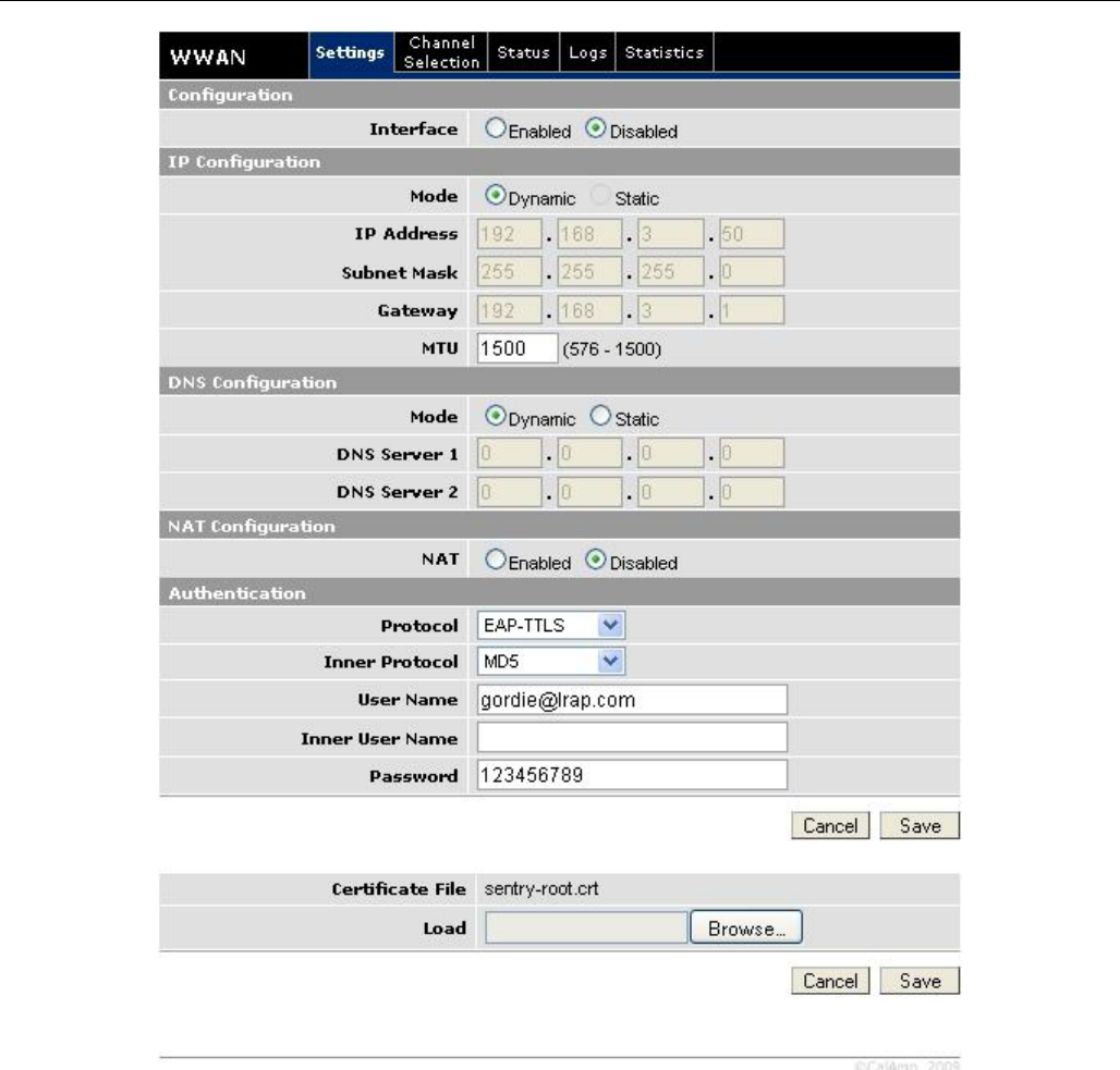
5.3.1 Settings
This screen contains main WWAN configuration. Select “Enabled” to enable WWAN interface and
“Disabled” to disable WWAN interface.
The Sentry 4G router uses EAP-TTLS (Extensible Authentication Protocol-Tunneled Transport Layer
Security) to obtain authorization and traffic key material from the BTS. The EAP-TTLS is disabled by
default.

CONFIGURATION
001-9193-001 Version 2 Page 22 of 52 Sentry 4G TM User
Manual
To enable EAP-TTLS authentication:
Under “Authentication” select “EAP-TTLS” from the Protocol drop-down box. This is the
Protocol type used for authentication.
Select the desired Protocol from the Inner Protocol drop-down box. This identifies Protocol
used for USER authentication.
Fill in the User Name. Usually identifies user’s organization.
Fill in the Inner User Name and Password fields. Used by Inner Protocol for authentication.
Click “Save”
Click “Browse” to locate certificate file supplied by the backhaul provider and click “Save”
Contact your backhaul provider for more information.
CONFIGURATION
001-9193-001 Version 2 Page 23 of 52 Sentry 4G TM User
Manual
Figure 8 – Sentry 4G Router WWAN Settings
CONFIGURATION
001-9193-001 Version 2 Page 24 of 52 Sentry 4G TM User
Manual
5.3.1.1 DNS Configuration
DNS servers can be configured as follows:
Mode:
Dynamic (Default): Obtain DNS IP addresses dynamically from a DHCP server.
Static: The DNS IP addresses are configured by the user.
DNS Server 1:
IP address of DNS server 1.
DNS Server 2:
IP address of DNS server 2.
5.3.1.2 NAT Configuration:
When NAT is enabled, the LAN interfaces (ETH0, ETH1, WLAN(Access Point)) are considered private,
the WWAN is considered public. Any IP packets leaving the Sentry 4G unit through the LAN interface
will have its source IP address changed to that of the WWAN interface.
Any data transfer must be initiated from the private side of the network toward the public side.
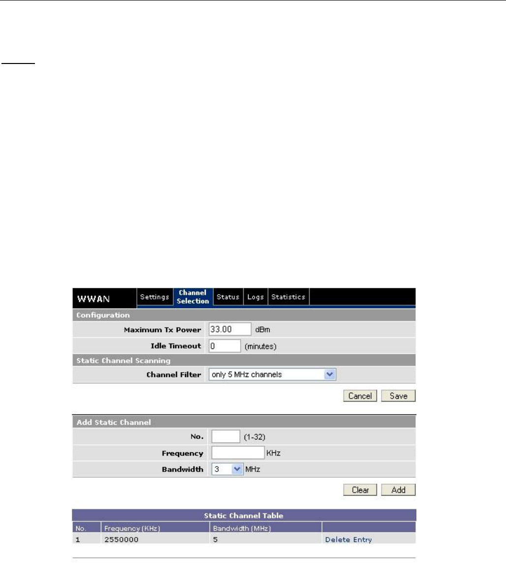
5.3.2 Channel Selection
Figure 9 – Sentry 4G WWAN Channel Selection
Maximum Tx Power: The maximum advertized power of the WWAN interface (Max 34.00).
Idle Timeout: The timeout before entering idle mode (Not Yet Implemented).
Channel Filter: The mask that defined the channels to use.
CONFIGURATION
001-9193-001 Version 2 Page 25 of 52 Sentry 4G TM User
Manual
To add a channel in the channel table:
Enter the desired number in No.
Enter the frequency
Using the drop-down menu select the Bandwidth
Click “Add”.
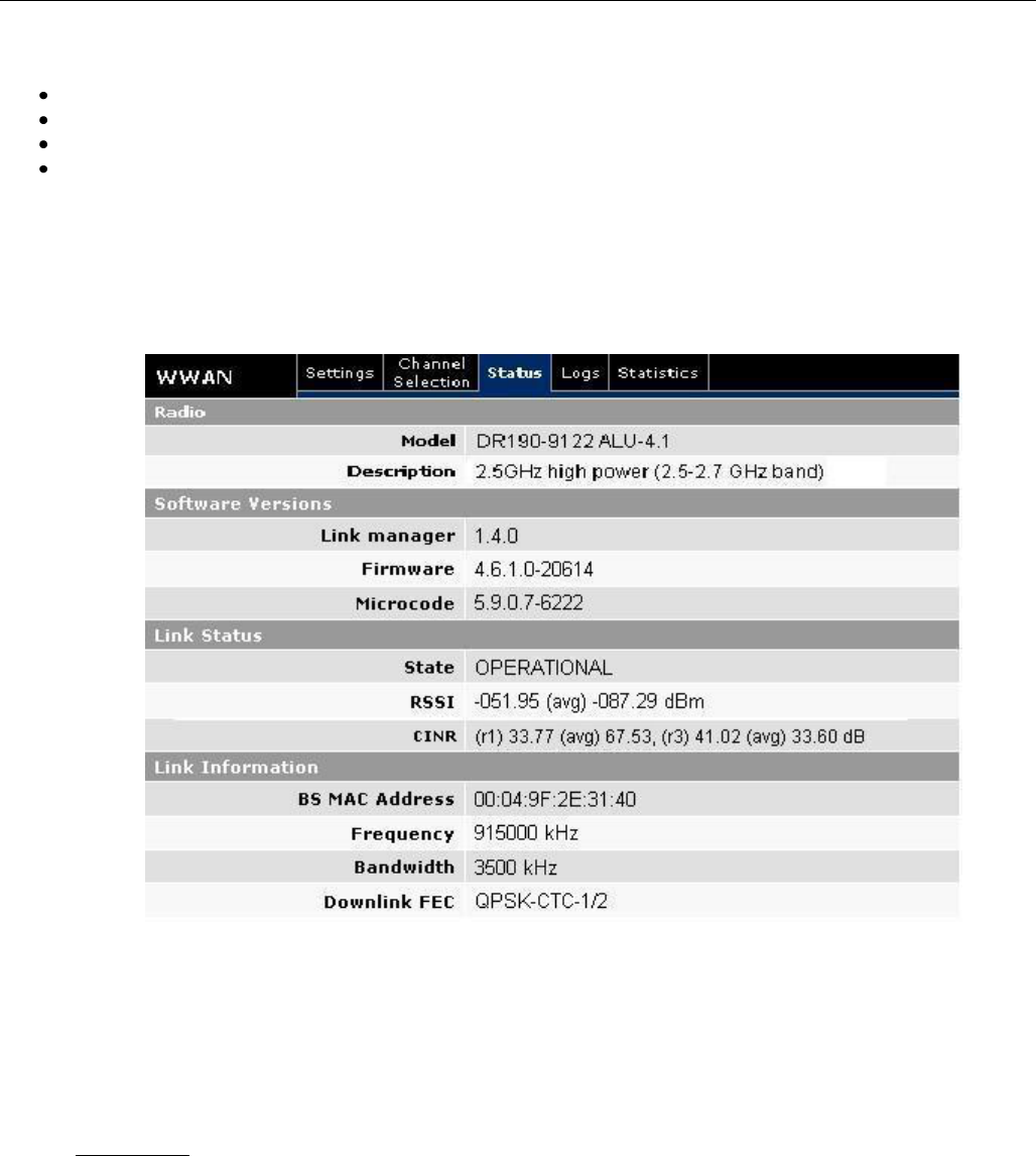
5.3.3 Status
The Status tab of the WWAN page displays the current WWAN interface status including firmware
version, link status, and link information. Information on this page is read-only.
Figure 10 – Sentry 4G Router WWAN Status
Once EAP-TTLS authentication is enabled, the IP configuration for the WWAN interface will be
obtained through the BTS. Note: The IP address for the WWAN interface is displayed under
the Unit Status
If no authentication is selected, the IP address for the WWAN interface must be entered
manually (see WWANSettings)
Link Status
The RSSI information displays the average value and the instantaneous value. The average
is to be considered.
The CINR information displays reuse1, reuse3 and preamble values.

CONFIGURATION
001-9193-001 Version 2 Page 26 of 52 Sentry 4G TM User
Manual
5.3.4 Statistics
This tab displays information regarding the number of packets and bytes transmitted and
received over the WWAN interface.
CONFIGURATION
001-9193-001 Version 2 Page 27 of 52 Sentry 4G TM User
Manual
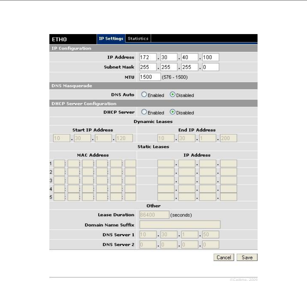
5.4 LAN Settings (ETH0 and ETH1)
Figure 11 - IP Settings
Sentry 4G features two Ethernet ports. The ETH0 and ETH1 IP Settings pages contain the
basic configuration information required to customize your LAN with the Sentry 4G router as
the network connection point. User configuration will primarily occur on this page.
5.4.1 IP Settings
5.4.1.1 IP Configuration
Ethernet IP address: LAN IP of the Sentry 4G unit. This address is entered into a browser
on a local PC when logging into the Sentry 4G home page. To decrease the chances of
unwanted access, this value should be changed from its default prior to use.
IMPORTANT NOTE:

CONFIGURATION
001-9193-001 Version 2 Page 28 of 52 Sentry 4G TM User
Manual
Changing this value will cause you to lose connection to the Sentry 4G unit.
Enter the new address in the browser to reconnect. If you forget an address or
make a mistake entering the new value, it may be difficult to reconnect to the
device.
Ethernet Subnet Mask: The Subnet mask is used in conjunction with the Ethernet IP
address to partition the address into the network (subnet) portion and the host portion. This
value will be entered automatically by the software based on the class of IP address entered.
It is not be necessary to change the default value once the Ethernet IP is entered.
5.4.1.2 DNS Masquerade
See the definition for DNS in Network Basics in section 3.1 above.
DNS Auto: The command enables/disables the Sentry 4G DNS server. Except in special
cases, this should always be enabled.
5.4.1.3 DHCP Server Configuration
DHCP Server: (Dynamic Host Configuration Protocol) A protocol used by client devices that
are connected to the LAN port of this device to automatically obtain an IP address assigned
by this server/router. Selecting Enable will configure this device to assign IP addresses to
client devices taken from a pool specified by the values entered in DHCP start range and
DHCP end range. If DHCP is disabled, the information must be entered manually on all PCs.
DHCP Start IP Address/End IP Address: Sets the range of IP addresses assigned to the
PCs. The user can limit the number of devices allowed on the network by limiting the range of
IP addresses.
IMPORTANT NOTE:
The addresses in this range must be on the same subnet as the Ethernet IP
IMPORTANT NOTE:
The Ethernet IP should not be in the DHCP range.
DHCP Lease Time: Number that dictates the length of time a device on the LAN can hold an
IP address. In most cases, this should be set to the maximum (default value) of 86400. If
this value is set too low, it can cause network connectivity problems.
Domain Name Suffix: The DNS suffix to be assigned by the DHCP server.
Preferred DNS Server: IP address of the preferred DNS server.
Alternate DNS Server: IP address of the alternate DNS server.
5.4.1.4 Disabling DHCP server
When DHCP server is enabled, any PC with physical access to the Sentry 4G Ethernet port will
be assigned an IP address and have access to browse the Internet. This may cause security
problems. Disabling DHCP server will allow the user to control which PCs have the ability to
connect through the Sentry 4G unit. If changes are made to the network settings, be sure to
keep a record of the changes for future use.
Disabling DHCP server is performed on the LAN settings page. Under the DHCP section,
select Disable, then click Save.
IMPORTANT NOTE:
This also disables DNS Masquerading. Disabling DHCP server will remove all values
in the DHCP and DNS sections. Record all values in these fields prior to disabling in
case you are required to go back to the original configuration.
To improve security, change the Ethernet IP of the Sentry 4G unit from the default
setting.
CONFIGURATION
001-9193-001 Version 2 Page 29 of 52 Sentry 4G TM User
Manual
IMPORTANT NOTE:
If the DHCP server is disabled, and you do not have a record of the Ethernet IP,
you will not be able to login to the Sentry 4G router home page.
On the network setting page of each PC set the following
– IP address: Set a unique address on the same subnet as the Sentry 4G
– Subnet Mask: Set to the same value as the Sentry 4G Ethernet Subnet Mask field
– Default Gateway: Ethernet IP of the Sentry 4G
– Preferred DNS: Ethernet IP of the Sentry 4G
When these settings are complete, the PC will have network access.
5.4.1.5 Static IP Setup
If your network requires each PC to have a statically set LAN IP addresses, follow the
previous procedure for all PCs on the network. If the network requires a mix of static and
dynamically assigned IP addresses, assign static IPs outside the DHCP address range for PCs
that require static IP addresses and allow the Sentry 4G DHCP to assign the remaining PC IP
addresses.
5.4.2 Statistics
This tab displays information regarding the number of packets and bytes transmitted and
received over the ETH0 or ETH1 interface.
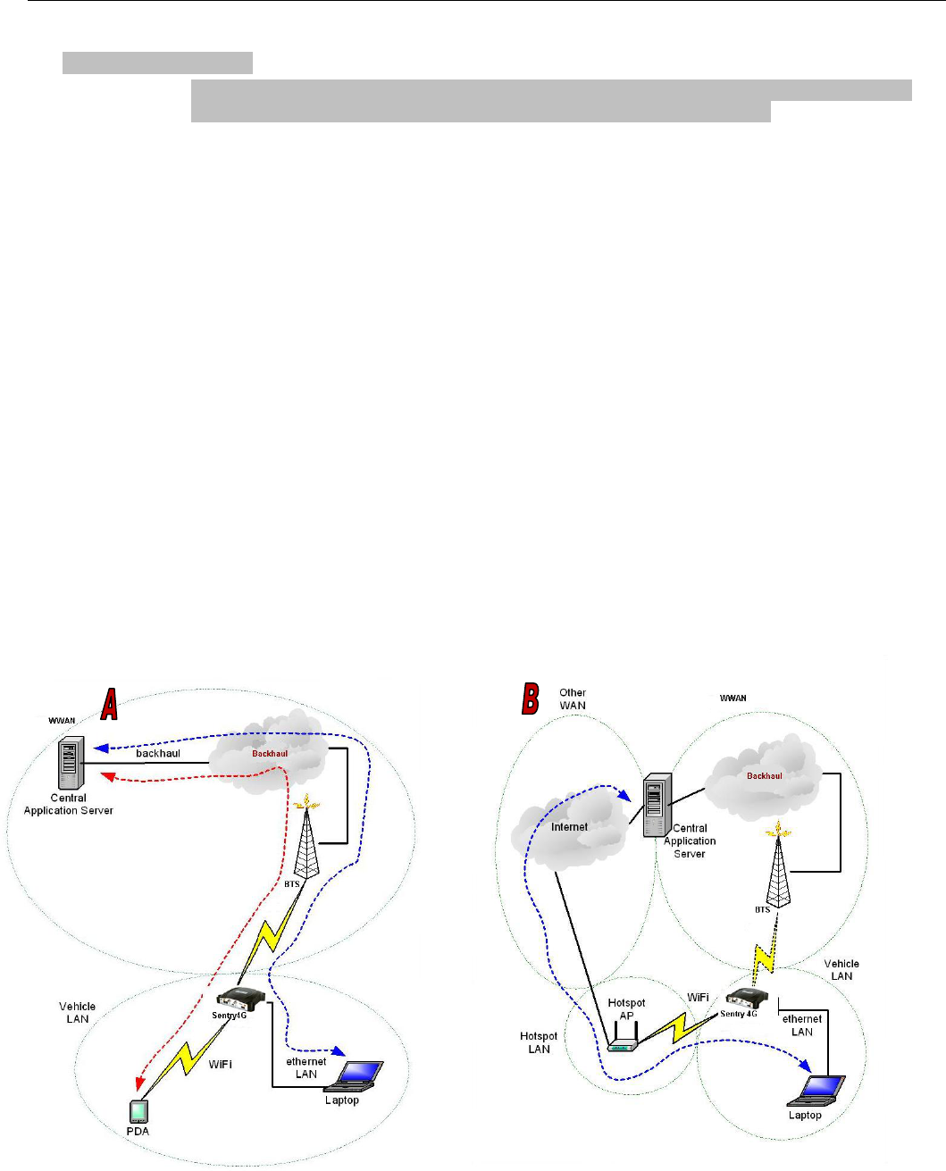
5.5 WiFi (WLAN)
A Sentry 4G unit can simultaneously operate in an access point mode and in a client mode.

CONFIGURATION
001-9193-001 Version 2 Page 30 of 52 Sentry 4G TM User
Manual
Figure 12 - Sentry 4G Router WiFi Modes: Access Point (A); Client Mode (B)
In access point mode, the Sentry 4G router offers wireless tether. It forwards local WiFi
traffic to application servers over the broadband 802.16-2005 network and works in parallel
with Ethernet connection, providing for simultaneous WiFi and Ethernet connections (see
Figure 12A).
In client mode the Sentry 4G unit can automatically switch between broadband 802.16-2005
and WiFi connections providing for seamless handover when coupled with modern
applications (see Figure 12B).
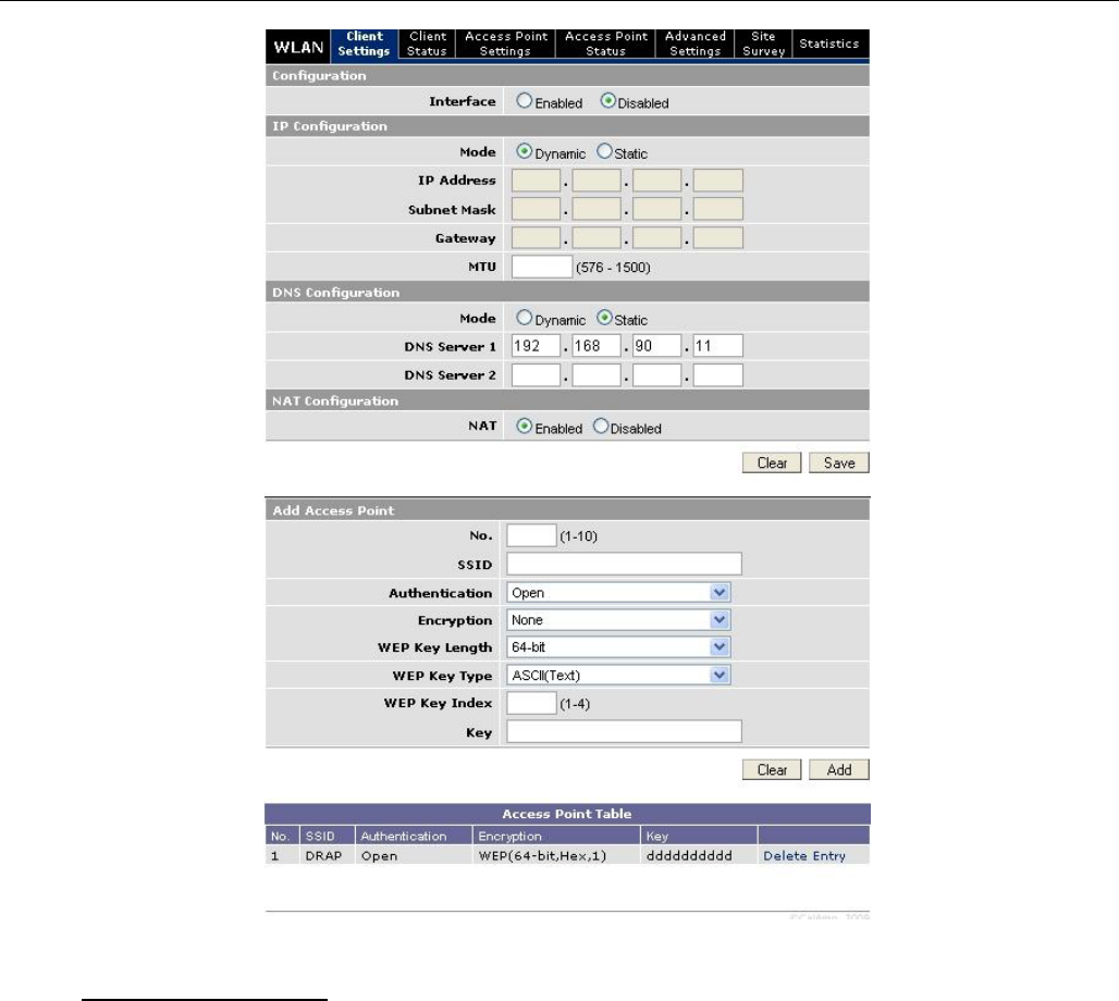
5.5.1 WiFi (WLAN)Wireless Settings (Client)
The user can configure up to 20 access points.
Note: All access points must run a DHCP server.
In wireless client mode, the Sentry 4G unit will try to connect to the Access Point with the strongest
signal on the list. When the Sentry 4G unit connects to an access point, it starts a DHCP client
service. The DHCP server running on the access point must provide an IP address, netmask, and
gateway to the Sentry 4G unit. When the WiFi client is connected to a WiFi access point, the default
route is set to point to the gateway address obtained by the DHCP client.
CONFIGURATION
001-9193-001 Version 2 Page 31 of 52 Sentry 4G TM User
Manual
Figure 13 - WiFi (WLAN)
Wireless Settings (Client)
To Add Access Point
Access Point Number: Access point number
SSID: Service Set Identifier. This is the name of the wireless local area network.
Channel: Channel number to use (Auto or 1-11)
Authentication: Authentication method to be used (Example: Open, Shared, WPANONE,
WPA-PSK, WPA2-PSK)
Encryption: None, WEP, TKIP, or AES
WEP Key Length: the bit key length
WEP Key Type: type of WEP security
WEP Key Index: 1-4
Key: The encryption key
Note: For a 64-bit key, keys are 5 character strings long if WEP Key Type is set to ASCII and
10 hexadecimal digits long if WEP Key Type is set to HEX.

CONFIGURATION
001-9193-001 Version 2 Page 32 of 52 Sentry 4G TM User
Manual
For a 128-bit key, keys are 13 character strings long if WEP Key Type is set to ASCII and 26
hexadecimal digits long if WEP Key Type is set to HEX.
The following table shows examples of encryption keys depending on encryption type chosen.
Table 4 - Encryption Keys Examples
Encryption Type
Description
Key (Example)
WEP Encryption
64-bit/ASCII
5 character string
CrYpT
64-bit/Hexadecimal
10 hexadecimal digits
mYEncryptKeY4
128-bit/ASCII
13 character string
LongHello1234
128-bit/Hexadecimal
26 hexadecimal digits
12345678901234567890ABCDEF
TKIP Encryption
Any Key
A string of 8 to 63
characters
AbCdEfGhIjKlMnOp
AES Encryption
Any Key
A string of 8 to 63
characters
AbCdEfGhIjKlMnOp
CONFIGURATION
001-9193-001 Version 2 Page 33 of 52 Sentry 4G TM User
Manual
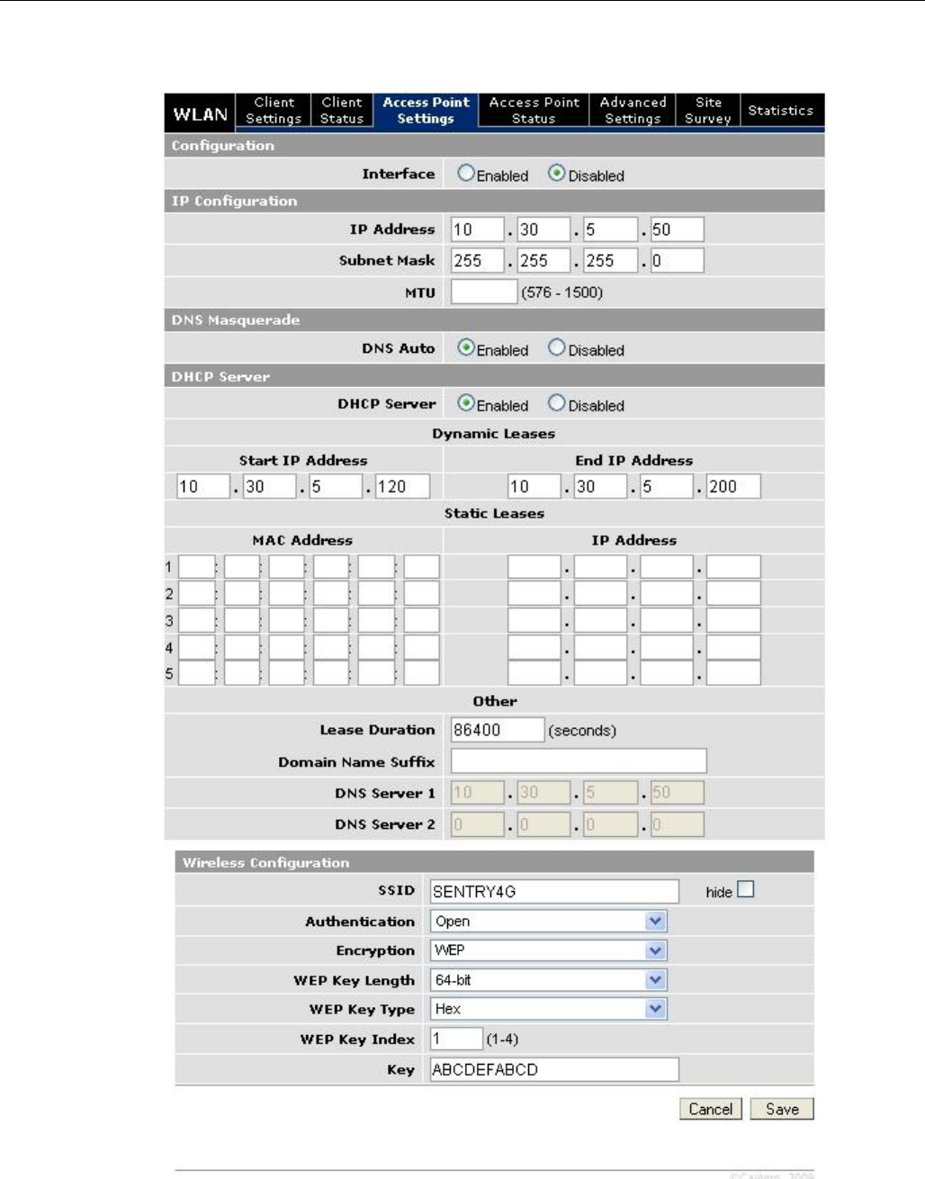
5.5.2 WiFi (WLAN)Wireless Settings (Access Point)
Figure 14 - WiFi (WLAN)
Wireless Settings (Access Point)

CONFIGURATION
001-9193-001 Version 2 Page 34 of 52 Sentry 4G TM User
Manual
IP Configuration
IP Address: IP address of the WiFi interface
Subnet Mask: The network mask of the WiFi interface
DNS Masquerade
DNS Auto: Enables or disables the Sentry 4G DNS server on the WiFi interface
DHCP Server
DHCP Server: Enables or disables DHCP server on the WiFi interface
Start IP Address: Starting IP address (defines the pool of addresses allocated for DHCP
purpose)
End IP Address: Ending IP address (defines the pool of addresses allocated for DHCP
purpose)
Lease Time: The period over which the IP address allocated to a DHCP client is referred to
as a “lease”. Lease duration is the amount entered in seconds.
Domain Name Suffix: DNS suffix to be assigned by the DHCP server
Preferred DNS Suffix: IP address of the preferred DNS server
Alternate DNS Suffix: IP address of the alternate DNS server
Wireless Configuration
SSID: Service Set Identifier. This is the name of the wireless local area network.
Channel: Channel number to use (Auto or 1-11)
Authentication: Authentication method to be used (Example: Open, Shared, WPANONE,
WPA-PSK, WPA2-PSK)
Encryption: Encryption method currently used
WEP Key Length: the bit key length
WEP Key Type: type of WEP security
WEP Key Index: 1-4
Key: The encryption key
Note: For a 64-bit key, keys are 5 character strings long if WEP Key Type is set to ASCII and
10 hexadecimal digits long if WEP Key Type is set to HEX.
For a 128-bit key, keys are 13 character strings long if WEP Key Type is set to ASCII and 26
hexadecimal digits long if WEP Key Type is set to HEX.
Refer to Table 4 for examples of encryption keys depending on encryption type chosen.
CONFIGURATION
001-9193-001 Version 2 Page 35 of 52 Sentry 4G TM User
Manual
5.5.3 WiFi (WLAN)Wireless Settings (Advanced)
Not supported in the current version.
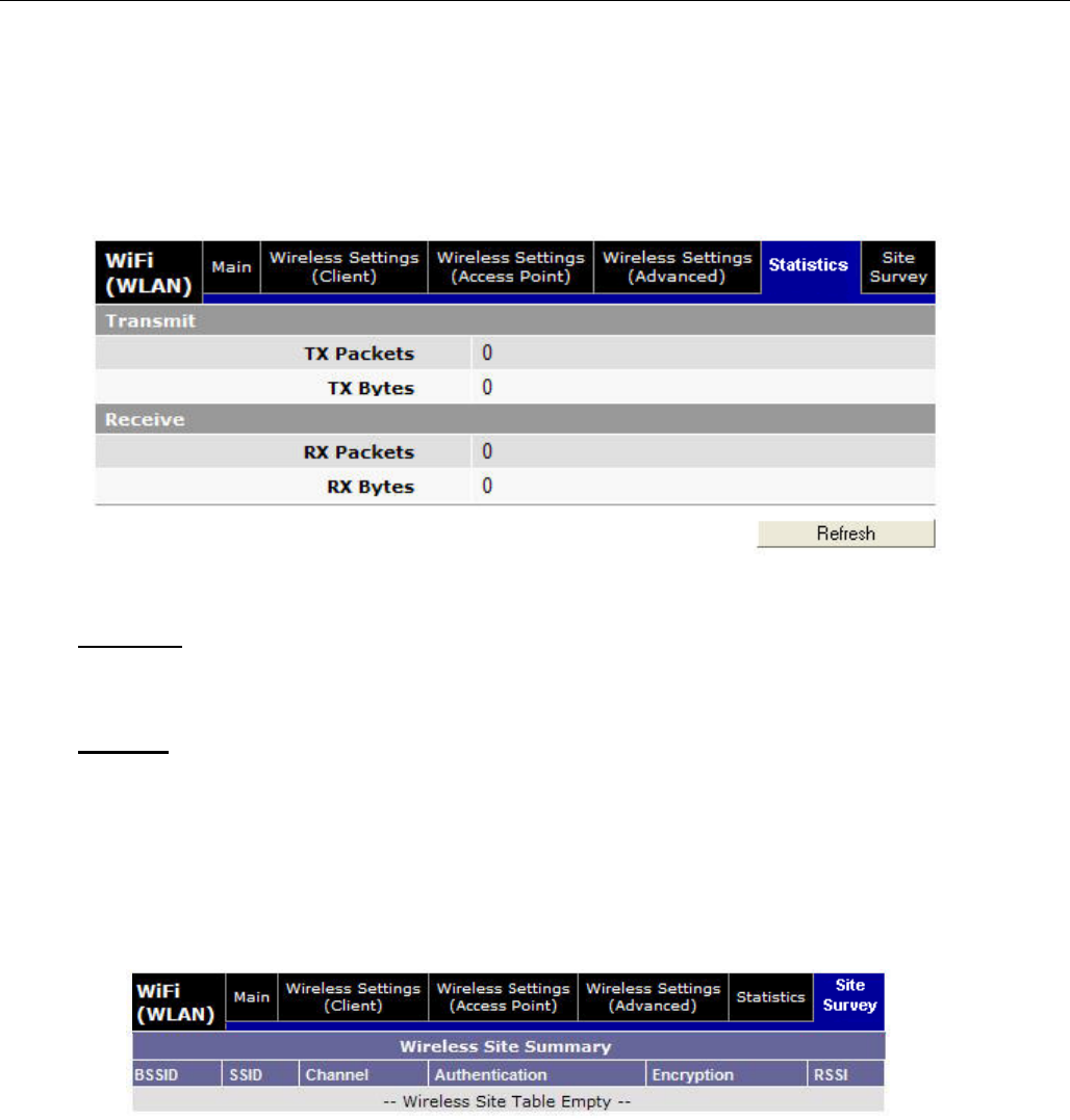
5.5.4 WiFi (WLAN)Statistics
Figure 15 - WiFi (WLAN)
Statistics
Transmit
TX Packets: Number of packets sent by the Sentry 4G unit over the WiFi interface
TX Bytes: Number of bytes sent by the Sentry 4G unit over the WiFi interface
Receive
RX Packets: Number of packets received by the Sentry 4G unit over the WiFi interface
RX Bytes: Number of bytes received by the Sentry 4G unit over the WiFi interface
5.5.5 WiFi (WLAN)Site Survey
Figure 16 - WiFi (WLAN)
Wireless Settings (Site Survey)
When the WiFi interface of the Sentry 4G unit operates in Client mode, this screen shows the
WiFi Access Point detected during last wireless scan.
The list is empty when the Sentry 4G unit is operating in Access Point mode.
CONFIGURATION
001-9193-001 Version 2 Page 36 of 52 Sentry 4G TM User
Manual
5.6 Router Settings
Router settings provide advanced user configuration for large network setups.
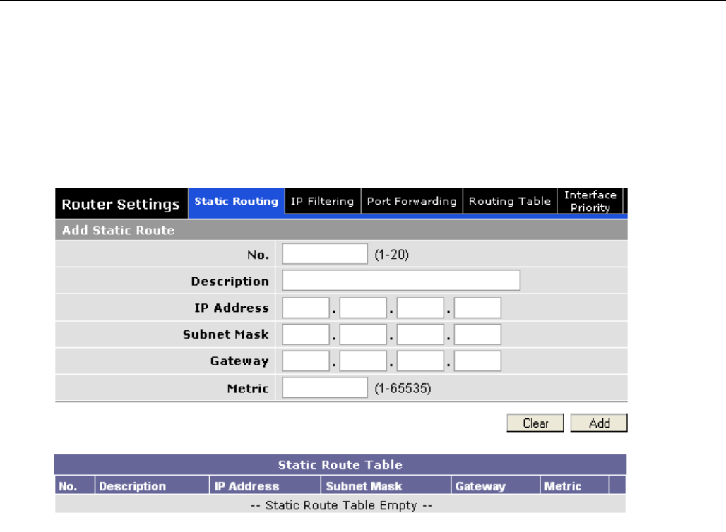
5.6.1 Static Routes
Figure 17 - Static Routes
The Sentry 4G unit will automatically set up routing to all devices on the same subnet. In
some cases however, the Sentry 4G unit may need to communicate with a previously existing
subnet other than its own. This route cannot be automatically generated; it must be manually
entered as a static route by the user. The static route gives the Sentry 4G router its “next
hop” instructions.
Route no: A generic number assigned to the route. Multiple static routes can be assigned as
long as they have distinct route numbers.
Description: Nickname assigned to the route by the user.
IP Address: This is the destination IP address that is delivered to the Sentry 4G unit. Since
this IP address will not be on the same subnet, the Sentry 4G unit will not have a defined
route, and will not know where to send it by default. Setting up the static route will inform
the Sentry 4G unit where to send the data.
Subnet Mask: The Subnet mask is determined by the subnet of the destination address
Gateway: This is the address that the data packet will be routed to.
Note:
The device at this address must be a router that is either on the same subnet as the
Destination IP or one with its own statically setup route to the destination address. If this
is not the case, the packet data will be dropped.

CONFIGURATION
001-9193-001 Version 2 Page 37 of 52 Sentry 4G TM User
Manual
Metric: This sets the priority of the routes compared to other static routed defined. The
lower the number, the higher priority the route.
Click on “Add” when all necessary information has been entered. The route will be shown on
the bottom of the screen (under Static Routing Table). Additional routes can be added
provided they have a unique Route no, name and metric. Routes can be deleted by clicking
the Delete Entry option of the desired entry.
Note:
Routing table (found under “Routing Table” tab) shows all routes, while Static Table
(found under “Static Routing” tab) shows manually entered routes only.
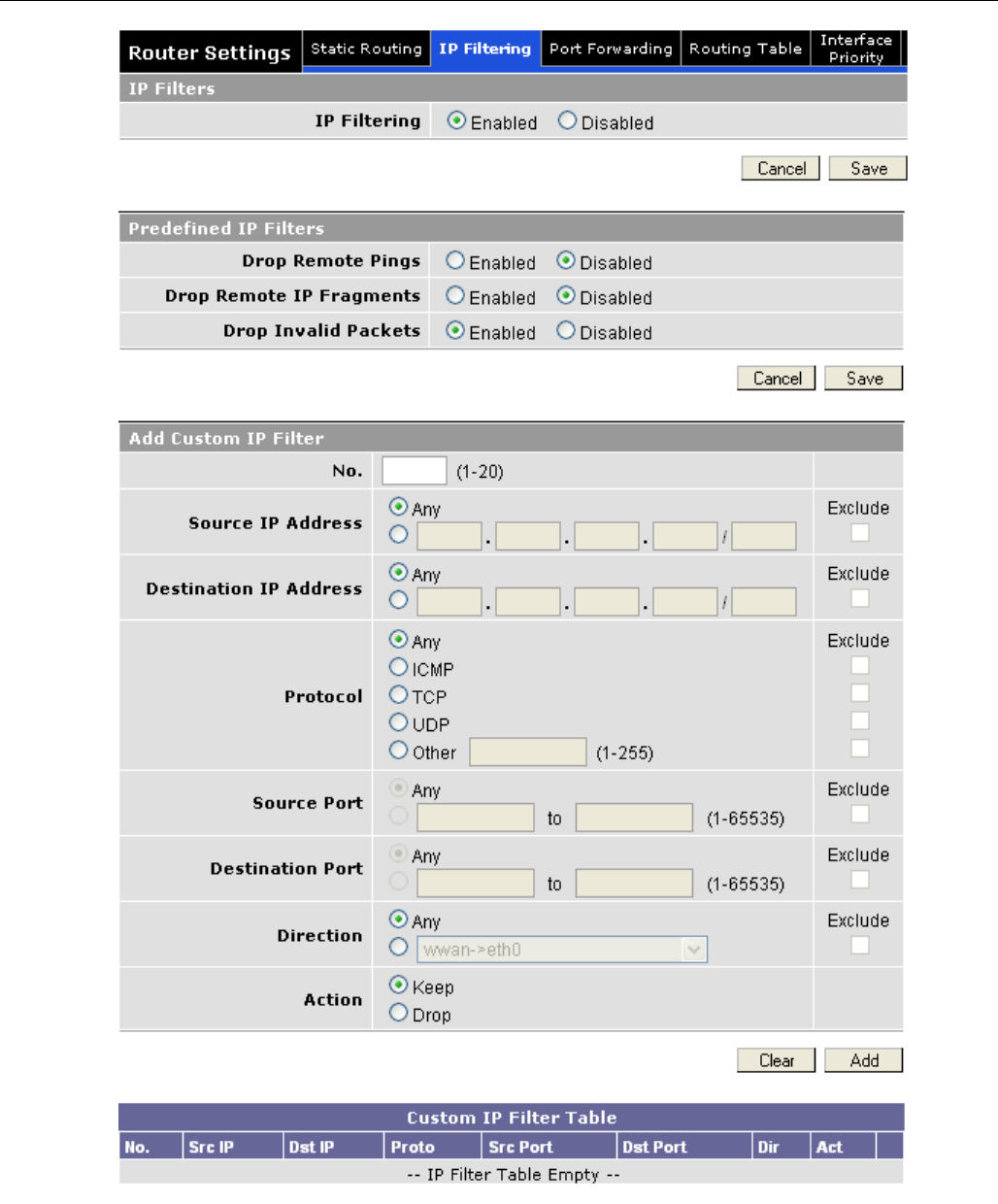
5.6.2 IP Filtering
IP Filtering provides certain Internet firewall protection. The user can enter up to 20 IP filters. Each
IP filter is identified by a unique number (from 1 to 20). When IP filtering is enabled, any custom IP
filter entered by the user as well as predefined IP filters will be taken into account when processing
IP packets. See Figure 18.
An IP packet passes through the filtering logic when IP filtering is enabled:
1) An IP packet is received on one of the interface and is destined to the Sentry 4G unit
OR
2) An IP packet is sent by the Sentry 4G unit
OR
3) An IP packet is forwarded by the Sentry 4G unit.
5.6.2.1 Predefined IP Filters
Drop Remote Pings: If IP filtering is enabled, any ICMP echo request coming from the WAN
interface will not be replied to. This prevents remote hosts from detecting your IP address on the
WAN.
Drop Remote IP Fragments: If IP filtering is enabled, any fragmented IP packets coming from the
WAN interface will be dropped.
Drop Invalid Packets: If IP filtering is enabled, any invalid packet received by the unit will be
silently dropped. An invalid IP packet is one that cannot be identified.
5.6.2.2 Add Custom IP Filters
Fill in the parameters described below and click “Add…”. Your entry will appear in the Custom IP
Filters table on the bottom of the page.
Note: Criteria are for inclusion by default. Select “exclude” if your criterion is for exclusion.
Filter Number: Each IP filter is identified by a unique number from 1 to 20.
CONFIGURATION
001-9193-001 Version 2 Page 38 of 52 Sentry 4G TM User
Manual
Figure 18 - IP Filtering
CONFIGURATION
001-9193-001 Version 2 Page 39 of 52 Sentry 4G TM User
Manual
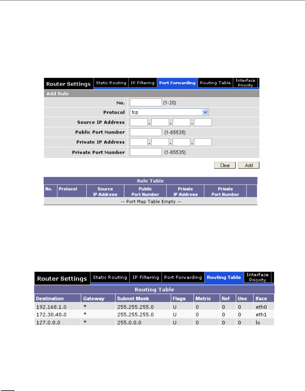
5.6.3 Port Forwarding
Port Forwarding is used to provide remote access to third party devices on the LAN, such as Web
Cameras or printers. Port Forwarding routes incoming requests from the WWAN, with a specific port
to a local device with a static IP. Note: the value 0.0.0.0 can be entered in the Source IP Address if
data from any IP Address is to be forwarded.
Figure 19 - Port Forwarding
5.6.4 Routing Table
The table in Figure 20 shows a list of all routes (static and dynamic).
Figure 20 - Routing Table
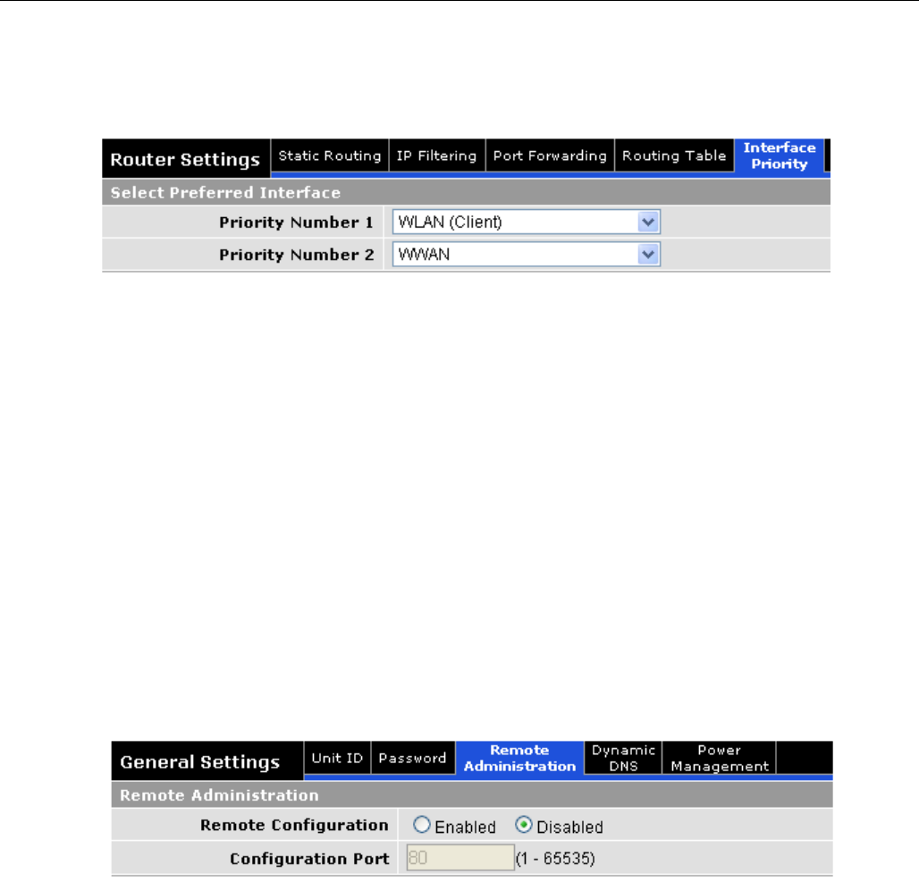
5.6.5 Interface Priority
When there is more than one WAN interface up at the same time, the unit needs to make a selection
on where to put the default route and what DNS servers must be used. To select interface priority
navigate to Interface Priority tab under Router Settings (see Figure 21).
Note: Highest priority is given to the interface identified as having Priority Number 1.
CONFIGURATION
001-9193-001 Version 2 Page 40 of 52 Sentry 4G TM User
Manual
Figure 21 - Interface Priority
5.7 General Settings
5.7.1 General Settings-Unit ID
The Sentry 4G unit identification number is configured under General SettingsUnit ID.
5.7.2 Advanced Settings-Password
The Sentry 4G unit’s web interface management login details are modified using the Password tab of
the Advanced Settings page.
To change the login details, enter the current and new password. The new password must be
entered twice (reconfirmed).
5.7.3 General Settings-Remote Administration
Figure 22 - Remote Admin
5.7.3.1 Remote Admin
Remote Configuration: Selecting Enabled will allow remote access to the unit’s
configuration screens through the WWAN network connection. Selecting Disabled will shut off
the ability to remotely access the unit’s configuration screens.
Configuration Port: Change the port of incoming requests. It is not necessary to change
this parameter unless it conflicts with other devices on the network.
Users can be logged into a single unit both locally and remotely at the same time.
Changes made on one end will not be reflected on the other unless the web page is
refreshed.
CONFIGURATION
001-9193-001 Version 2 Page 41 of 52 Sentry 4G TM User
Manual
5.7.3.1.1 Example of Remote Login
The following should be entered into a browser on a remote PC to remote login to the Sentry 4G.
The Sentry 4G unit must have remote administration enabled for this functionality to work.
http://70.209.115.93:8080
Figure 23 - Example of Remote Login
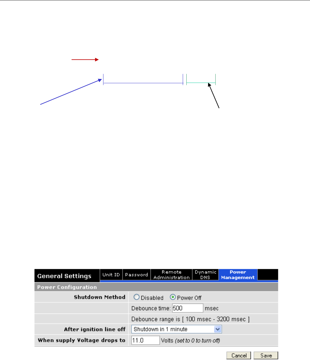
5.7.4 General Settings-Power Management
The Sentry 4G unit is designed to stay ON even if the ignition is turned OFF. You can configure your
Sentry 4G unit to automatically shut down 1, 5, 30, or 60 minutes after ignition is turned off or when
the supply voltage drops to a certain level.
Shutdown Method: Disabled by default (unit always ON after ignition is turned OFF). Select
“Power Off” to enable power management.
After ignition line off: Select between the following time intervals: 1 minute, 5 minutes, 30
minutes, or 60 minutes.
When Voltage Drops to: Enter desired voltage. Enter “0” to disable. (Note: A value of 11V would
be usually entered here as a precaution in order to ensure the car battery does not drain.)
Figure 24 - Power Management
“WWAN IP Address"
On Unit Status page
"Configuration Port" on
"Remote Administation"
page.
Note: “HTTP” must be
specified or browser will
assume other uses
CONFIGURATION
001-9193-001 Version 2 Page 42 of 52 Sentry 4G TM User
Manual
5.8 GPS Status and Settings
The Sentry 4G unit incorporates a highly sensitive 16-channel GPS receiver and an intelligent
algorithm that offers outstanding receive sensitivity. Summarized below are the specifications of the
integrated GPS module:
Typical sensitivity
-135 dBm
Reacquisition time
Less than 2 seconds
Average Cold/Warm/Hot Start time to first fix
Under 45/15/3.5 seconds
Position Accuracy
GPS Standard Positioning Service (SPS)
<15 meters
DGPS (WAAS) corrected
<3 meters
The GPS page allows the user to see the GPS status and configure remote or local delivery of GPS
position reports. Viewing the GPS data from a local or remote PC requires a UDP port listener
program be installed on the PC. Any UDP listener will work provided you can set an appropriate port
value for the program.
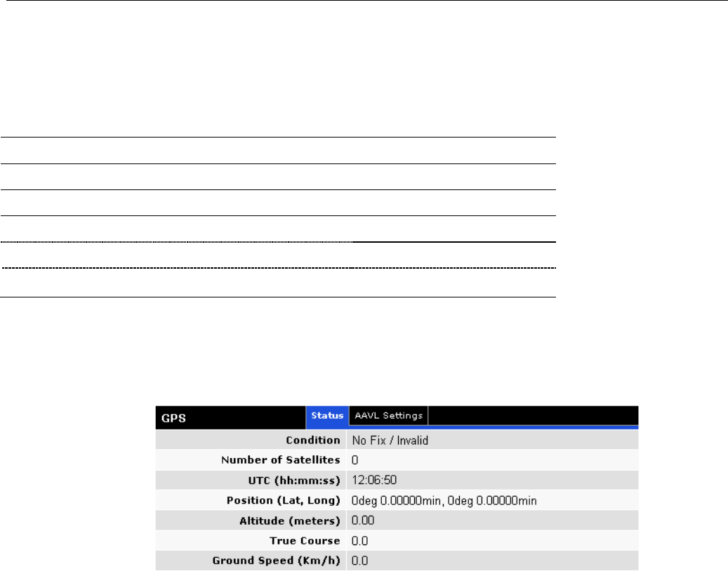
5.8.1 GPS Status
Figure 25 - GPS Status
Condition: Indicates No Fix, Standard GPS Fix, Differential GPS Fix, or Estimated / Last
Known Position
Number of Satellites: Indicates the number of satellites the GPS has locked on to. A
minimum of 3 is required to establish a position. Generally, the more satellites the GPS has
locked, the more accurate the position reporting will be.
UTC: Time of day in Universal Coordinated Time
Position: Device position reported in degrees and minutes
Altitude: Altitude from Mean Sea Level reported in meters.
True Course: Heading, reported in degrees (0 – 360)
Ground Speed: Reported in km/hr
CONFIGURATION
001-9193-001 Version 2 Page 43 of 52 Sentry 4G TM User
Manual
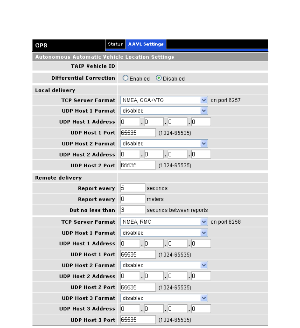
5.8.2 AAVL Settings (Local and Remote Delivery)
Figure 26 - AAVL Settings
TAIP Vehicle ID: User assigned number to identify the vehicle or Sentry 4G unit that each
GPS report belongs to. This will be reported in the GPS messages if TAIP with ID is
selected for TCP Server Format and/or UDP Host format. Configured under Basic
Settings.

CONFIGURATION
001-9193-001 Version 2 Page 44 of 52 Sentry 4G TM User
Manual
Differential Correction: Differential GPS corrects various inaccuracies in the GPS system to
yield measurements accurate to a couple of meters when the mobile is moving and
even better when stationary.
5.8.3 Local Delivery
The GPS data can be delivered to up to two local PCs with UDP viewer programs can provide data
through a TCP connection, e.g. telnet. GPS data will be delivered once per second to all local PCs
TCP Server Format: Select one of the following options for the format of the GPS messages
TAIP no ID: Trimble ASCII Interface Protocol, a Trimble specified digital
communication interface. When this option is selected, the TAIP vehicle ID is not
included in the GPS messages.
TAIP with ID: Same as above except the Vehicle ID is reported
NMEA National Marine Electronics Association interface specification for electronic
equipment. The NMEA GPS message set includes several message types, each
containing specific GPS information. See message descriptions below. TAIP Vehicle ID
is not reported when NMEA is selected.
NMEA GLL: Position in LAT/LONG coordinates and time of day in UTC coordinates.
NMEA GGA: Position in LAT/LONG coordinates, time of day in UTC coordinates, fix
quality, number of satellites and altitude
NMEA RMC: Position in LAT/LONG coordinates, time of day in UTC coordinates,
ground speed in knots, heading in degrees and date
NMEA VTG: Ground speed in kilometers per hour and knots, heading in degrees.
To get GPS data by telneting into the device, enter the following from a prompt
telnet <local IP address of the Sentry 4G > 6257.
Note:
It is possible to telnet to the Sentry 4G unit’s port 6257 from a remote location however
this is not recommended as delivering the data once per second across the broadband
802.16-2005 network will greatly increase the amount of data transferred.
UDP Host Format: Same options as TCP server format
UDP Host Address: IP address of local PC that GPS data will be delivered to. This address
must be on the same subnet as the Sentry 4G LAN IP
UDP Host Port: Port assigned to UDP program. This must match the port assigned in the
chosen UDP Port Listener Program.
5.8.4 Remote Delivery
The GPS data can be delivered to up to three remote PCs with UDP viewer programs running on the
host.
Report every: GPS can be programmed to report position after a specified time has elapsed
or the unit has moved a specified distance since its last report.
But no less than: This feature prevents a fast moving vehicle from reporting too frequently
if its “Report every ….. meters” setting is sufficiently low” by setting a minimum amount of
time, in seconds, between GPS reports.

CONFIGURATION
001-9193-001 Version 2 Page 45 of 52 Sentry 4G TM User
Manual
5.9 I/O Settings
The Sentry 4G router supports the following I/Os:
Ignition Sense
One external digital alarm
See Table 5 for pinout.
J4
Pin
Signal
I/O
Description / specification
1
Ignition
Sense
Input to
Sentry 4G
Standard ignition-on signal 1. Pin 1 is the left most pin when looking
directly at the front panel.
Maximum voltage above which Ignition Sense will be detected as
ignition asserted = 9.0V;
Minimum voltage below which Ignition Sense will be detected as
ignition de-asserted = 5.7V.
4
External
Alarm
Input to
Sentry 4G
Active low signal. To trigger an alarm, short this signal to VIN- using
a low impedance path (100-Ohm max)
For 200ms minimum. Otherwise, leave open or connect to VIN+. This
signal can also be driven from a 5V/3.3V TTL/LVTTL or CMOS circuit.
Table 5 - I/O Signal Pinout
CONFIGURATION
001-9193-001 Version 2 Page 46 of 52 Sentry 4G TM User
Manual
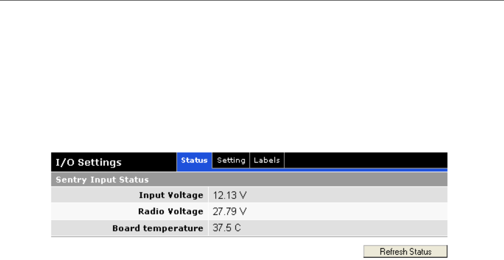
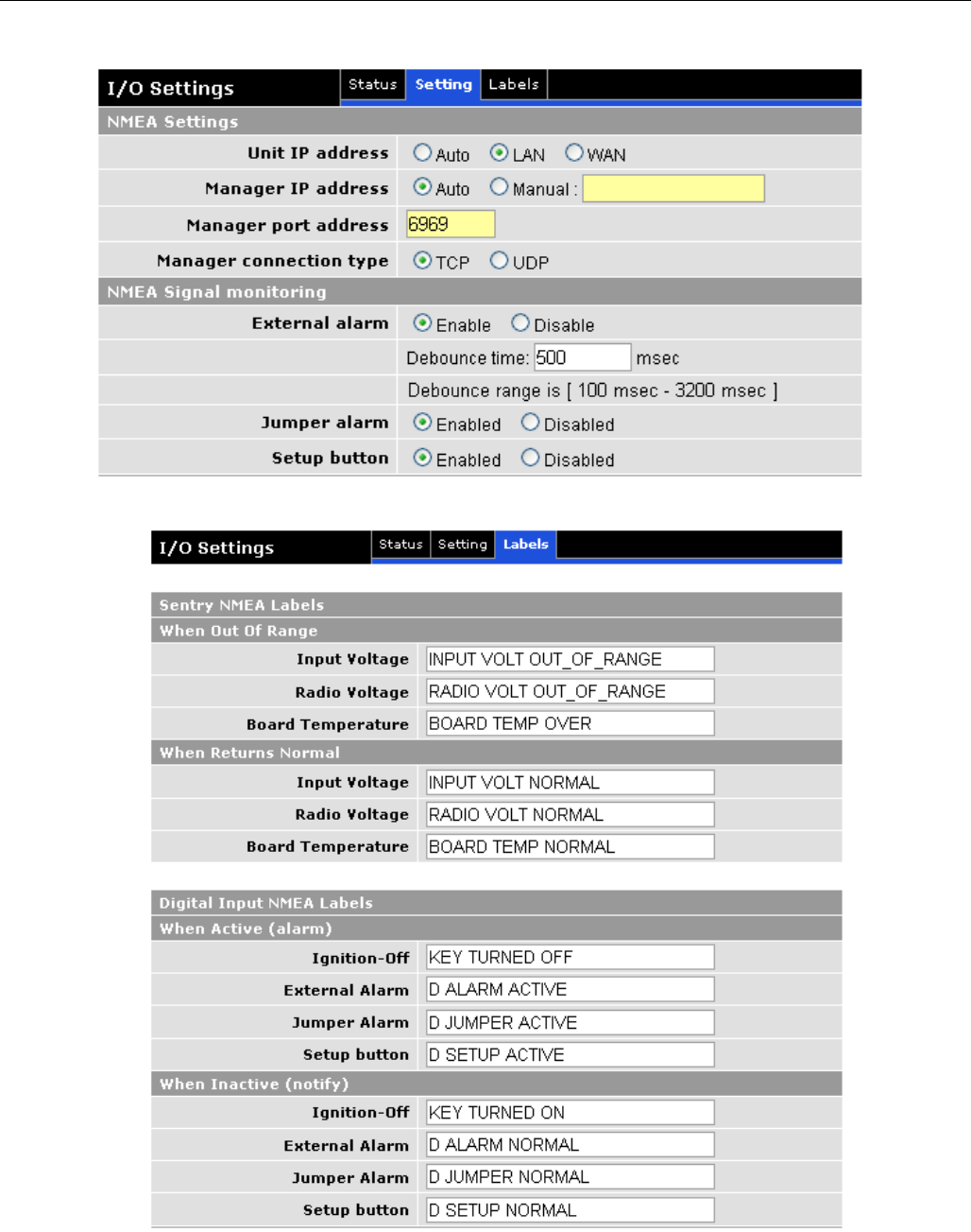
5.9.1 I/O Configuration
The Sentry 4G I/O subsystem is configured via the Sentry 4G WEB pages. Status Monitoring is
provided via NMEA-based protocol. The Sentry 4G I/O subsystem operates according to a
manager/agent model. The PC-hosted manager sends requests to the Sentry 4G I/O agent, which
performs the required actions. The Sentry 4G agent reports alarms and indications to the PC-hosted
manager.
Figure 27 - I/O Settings-Status
The Manager IP address is configured under I/O SettingsNMEA Settings Manager IP address
(see Figure 28).
The port number is 6969 by default and can be customized under I/O SettingsNMEA Settings
Manager IP address Port.
Note: If Auto is selected for “Manager IP address”, the Sentry 4G automatically computes the
manager IP address to be Sentry 4G ETH address +1 if DHCP is disabled. If DHCP is enabled, the IP
address is the starting address offered by the DHCP server.
The unit IP address is the source IP address (displayed in the alarm messages received by the
Manager). The user can configure this to be the WAN Sentry 4G IP address or the LAN (Ethernet)
Sentry 4G IP address. If auto is selected, the source IP address is automatically computed to be
Sentry 4G ETH address +1 if DHCP is disabled. If DHCP is enabled, the IP address is the starting
address offered by the DHCP server.
The user can enable and disable digital alarms by selecting appropriate “enabled” and “disabled”
radio buttons under I/O Settings (Error! Reference source not found. 28).
The alarm messages can be configured for each diagnostic value under I/O SettingsLabels (see
29).
CONFIGURATION
001-9193-001 Version 2 Page 47 of 52 Sentry 4G TM User
Manual
Remember to save your settings for each configuration.
Figure 28 - I/O Settings
Figure 29 - I/O Settings-Labels

CONFIGURATION
001-9193-001 Version 2 Page 48 of 52 Sentry 4G TM User
Manual
.
CONFIGURATION
001-9193-001 Version 2 Page 49 of 52 Sentry 4G TM User
Manual
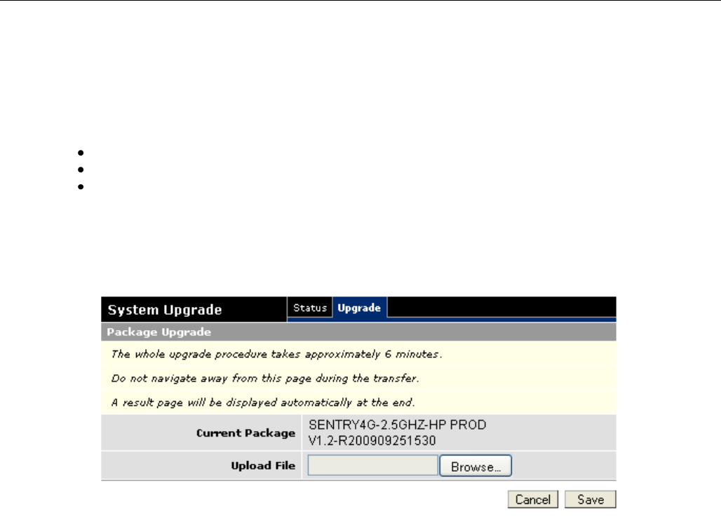
5.10 System Upgrade (Optional Service)
It is possible to update the system firmware by receiving an update file from CalAmp. This may be
done periodically to add features or fix errata. When you receive an update file, perform the
following to update the unit. Upgrading can only be performed from a local PC, not remotely.
Save the file on a local drive or network accessible directory.
On the System Upgrade page (see Figure 30), browse to the update file and select it.
Click Save. The system update can take up to 6 minutes. Do not navigate away from
the system upgrade page during the transfer. A result page will be displayed
automatically when the upgrade is completed.
Note: This will not delete your configuration settings.
Figure 31 - Sentry 4G Upgrade

SPECIFICATIONS
001-9193-001 Version 2 Page 50 of 52 Sentry 4G TM User
Manual
6. SPECIFICATIONS
Product specifications are subject to change without notice.
GENERAL SPECIFICATIONS
Interface Connectors: Two 10/100 BaseT auto-MDIX, RJ-45
USB A Female Client port1
3-wire RS-232 in a USB mini B female form factor
Power Connector: 4-pin Weidmuller 1615550000
LED Indicators: PWR, STAT, GPS, 4G, WiFi,3G, ETH0, ETH1
Antenna Interface: Two 4G Antennas: 50-Ohm TNC Female
GPS Antenna: 50-Ohm, 3.3V SMA Female
Two WiFi Antennas: 50-Ohm RP-SMA Plug
Two 3G Antennas: 50-Ohm SMA Female.
Size: 7 (L) x 7 (W) x 2.2(H) inches (17.8 x 17.8 x 5.6 cm)
Weight: 4 lbs (1.81 kg)
Power Input: 10-30 VDC
Current Drain:
(Average at 13.8 VDC)
TX Power Range: WWAN: BTS controlled, up to 34 dBM
WiFi: 26 dBm (802.11b) & 21-26 dBm (802.11g)
Frequency Range: WWAN: 2.496 GHz to 2.69 GHz
Channels: Static list
Modulation: S-OFDMA TDD QPSK, 16QAM, 64QAM
Diversity: 2x2 MIMO Matrix A
Operating Temperature: -30°C to +60°C (-22 to +140 °F)
Protocols: Ethernet / IPV4 suite, DHCP client/server, NAT
Management: HTTP embedded WEB server
1 Reserved for future use
Current Drain
TX
With WiFi module
3 A
Without WiFi module
2.2 A

ABBREVIATIONS
001-9193-001 Version 2 Page 51 of 52 Sentry 4G TM User
Manual
7. ABBREVIATIONS
Abbreviation
Description
BTS
Base Transceiver Station
CTS
Clear to Send
DHCP
Dynamic Host Configuration Protocol
DNS
Domain name Server
ESN
Electronic Serial Number
GPS
Global Positioning System
HSDPA
High Speed Downlink Packet Access
IP
Internet Protocol
LAN
Local Area Network
LED
Light Emitting Diode
NAT
Network Address Translation
PAD
Packet Assembly/Disassembler
PPP
Protocol Point to Point
PRL
Preferred Roaming List
RIP
Routing Information Protocol
RSSI
Receive Signal Strength Indication
RTS
Request to Send
WAN
Wide Area Network
WLAN
Wireless Local Area Network
WWAN
Wireless Wide Area Network
UART
Universal Asynchronous Receiver-Transmitter
USB
Universal Serial Bus

SERVICE AND SUPPORT
001-9193-001 Version 2 Page 52 of 52 Sentry 4G TM User
Manual
8. SERVICE AND SUPPORT
8.1 PRODUCT WARRANTY, RMA AND CONTACT INFORMATION
CalAmp Corp guarantees that every Sentry 4G will be free from physical defects in material
and workmanship for one (1) year from the date of purchase when used within the limits set
forth in the Specifications section of this manual. Extended warranty plans are available.
If the product proves defective during the warranty period, contact CalAmp Customer Service
to obtain a Return Material Authorization (RMA).
8.2 RMA REQUEST
8.3 PRODUCT DOCUMENTATION
8.4 TECHNICAL SUPPORT