CalAmp Wireless Networks 242-5099-100 Wireless Radiomodem User Manual Gemini PD Technical Manual
CalAmp Wireless Networks Corporation Wireless Radiomodem Gemini PD Technical Manual
Manual

HiPR-900™
Wireless Radiomodem
User Manual
Version 1.00
Preliminary
The entire contents of this manual are copyright 2005 by DATARADIO Inc.®
Copyright DATARADIO Inc.
February, 2005
Part no.: 120 40515-100a (FCC-2)
Table of Contents
1. PRODUCT OVERVIEW.................................................................................................................................9
1.1 INTENDED AUDIENCE ......................................................................................................................................9
1.2 GENERAL DESCRIPTION...................................................................................................................................9
1.2.1 Characteristics.....................................................................................................................................10
1.2.2 Accessories and Options......................................................................................................................10
1.2.3 Configuration.......................................................................................................................................11
1.3 FACTORY TECHNICAL SUPPORT ....................................................................................................................11
1.4 PRODUCT WARRANTY...................................................................................................................................11
1.5 REPLACEMENT PARTS ...................................................................................................................................11
1.5.1 Factory Repair.....................................................................................................................................11
1.6 UNPACKING...................................................................................................................................................12
2. INSTALLATION............................................................................................................................................13
2.1 PARALLEL DECODE .......................................................................................................................................13
2.2 ANTENNAE INSTALLATION............................................................................................................................13
2.2.1 Professional Installation & RF Exposure Compliance Requirements.................................................13
2.2.2 Antenna Connection ............................................................................................................................14
2.2.3 Spacing and Constraints......................................................................................................................14
2.2.4 Acceptable Antennae ...........................................................................................................................15
2.3 NETWORK APPLICATION................................................................................................................................15
2.3.1 Modes ..................................................................................................................................................15
2.3.1.1 Bridge mode.................................................................................................................................................15
2.3.1.2 Router mode.................................................................................................................................................15
2.3.2 RF Path and communications range ...................................................................................................16
2.3.3 COMMON CHARACTERISTICS ........................................................................................................16
2.3.4 Basic connections ................................................................................................................................16
2.3.5 POINT-TO-POINT SYSTEM ...............................................................................................................16
POINT-MULTIPOINT SYSTEM.......................................................................................................................17
2.4 SELECTABLE DATA RATES ............................................................................................................................18
2.5 COMBINED ACCESS POINT AND REMOTE.......................................................................................................18
2.6 ONLINE & OFFLINE DIAGNOSTICS.................................................................................................................18
2.7 BUILT-IN SPECTRUM ANALYZER...................................................................................................................18
3. PHYSICAL DESCRIPTION.........................................................................................................................19
3.1 FRONT PANEL................................................................................................................................................19
3.2 CABLES AND CONNECTOR PIN-OUTS.............................................................................................................20
4. OPERATION & CONFIGURATION..........................................................................................................21
4.1 LOCAL AND REMOTE (OTA) CONFIGURATION..............................................................................................21
4.2 OVER-THE-AIR FIRMWARE UPGRADE ...........................................................................................................21
4.3 BROWSER-BASED SETUP AND STATUS ..........................................................................................................21
4.3.1 LAN Setup............................................................................................................................................21
4.3.2 Login Screen........................................................................................................................................21
4.3.2.1 Initial Installation Login ..............................................................................................................................22
4.3.3 Interface...............................................................................................................................................23
4.3.3.1 Test & Save Parameters Buttons Behavior ..................................................................................................23
4.3.3.2 Unit Status ...................................................................................................................................................24
4.3.3.3 Setup (General)............................................................................................................................................24
4.3.3.4 Basic IP Configuration.................................................................................................................................24
4.3.3.5 RF Setup ......................................................................................................................................................24
4.3.3.6 Terminal Server Configuration ....................................................................................................................25
4.3.3.7 Advanced IP Configuration .........................................................................................................................25
4.3.3.8 RF Network Setup........................................................................................................................................25
120 40515-100a HiPR900 User Manual
1
4.3.3.9 Broadcast / Multicast ...................................................................................................................................25
4.3.3.10 IP Optimization & Tuning ...........................................................................................................................26
4.3.3.11 Simple Network Time Protocol ...................................................................................................................26
4.3.3.12 Hopper Network...........................................................................................................................................26
4.3.3.13 Security........................................................................................................................................................26
4.3.3.14 Network Statistics........................................................................................................................................27
4.3.3.15 Packet Statistics ...........................................................................................................................................27
4.3.3.16 Event Log.....................................................................................................................................................28
4.3.3.17 RF Test.........................................................................................................................................................28
4.3.3.18 FTP Transfer................................................................................................................................................28
4.3.3.19 RSSI Table...................................................................................................................................................29
4.3.3.20 Manuals & Support......................................................................................................................................29
5. TROUBLESHOOTING & TESTING..........................................................................................................30
5.1 HARDWARE REQUIREMENTS .........................................................................................................................30
5.2 SOFTWARE REQUIREMENTS...........................................................................................................................30
5.2.1 Ping......................................................................................................................................................30
5.2.2 HiPR-900 Web interface......................................................................................................................30
5.2.2.1 RF and IP Information .................................................................................................................................30
5.2.2.2 Status and Statistics......................................................................................................................................30
5.2.2.3 RF Tests.......................................................................................................................................................30
5.2.3 Windows/Unix Tools............................................................................................................................30
5.2.3.1 Network Connectivity..................................................................................................................................30
5.2.3.2 Configuration Information...........................................................................................................................30
5.2.3.3 Statistics Information...................................................................................................................................30
5.2.3.4 DNS .............................................................................................................................................................31
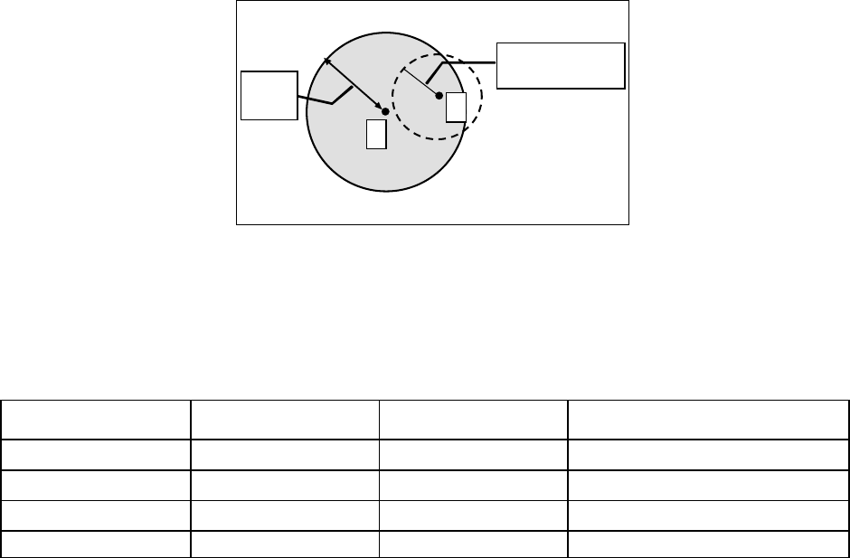
6. SPECIFICATIONS ........................................................................................................................................32
FIGURE 1 - HIPR-900...................................................................................................................................................9
FIGURE 2 - SAMPLE EQUATION...................................................................................................................................14
FIGURE 3 - ANTENNA SPACING...................................................................................................................................15
FIGURE 4 - BASIC SETUP ............................................................................................................................................16
FIGURE 5 - POINT-TO-POINT IP NETWORK SYSTEM ...................................................................................................17
FIGURE 6 - POINT-TO-MULTIPOINT SYSTEM...............................................................................................................17
FIGURE 7 - HIPR-900 FRONT PANEL..........................................................................................................................19
FIGURE 8 - ENTER NETWORK PASSWORD SCREEN......................................................................................................22
FIGURE 9 - WEB USER INTERFACE (PRELIMINARY)....................................................................................................22
FIGURE 10 - PARAMETER COMMAND BUTTONS BEHAVIOR ........................................................................................23
FIGURE 11 - STATION RESET CONFIRMATION ............................................................................................................23
TABLE 1 - ACCESSORIES ............................................................................................................................................10
TABLE 2 - ACCEPTABLE ANTENNAE...........................................................................................................................15
TABLE 3 - HIPR-900 LEDS INDICATIONS ...................................................................................................................19
TABLE 4 - UNIT STATUS.............................................................................................................................................24
TABLE 5 - SETUP (GENERAL) .....................................................................................................................................24
TABLE 6 - BASIC IP CONFIGURATION ........................................................................................................................24
TABLE 7 - RF SETUP ..................................................................................................................................................24
TABLE 8 - TERMINAL SERVER CONFIGURATION.........................................................................................................25
TABLE 9 - ADVANCED IP CONFIGURATION................................................................................................................25
TABLE 10 - RF NETWORK SETUP...............................................................................................................................25
TABLE 11 - BROADCAST / MULTICAST.......................................................................................................................25
TABLE 12 - IP OPTIMIZATION & TUNING...................................................................................................................26
TABLE 13 - SIMPLE NETWORK TIME PROTOCOL ........................................................................................................26
120 40515-100a HiPR900 User Manual
2
TABLE 14 - HOPPER NETWORK ..................................................................................................................................26
TABLE 15 - SECURITY ................................................................................................................................................26
TABLE 16 - NETWORK................................................................................................................................................27
TABLE 17 - PACKET STATISTICS.................................................................................................................................27
TABLE 18 - EVENT LOG .............................................................................................................................................28
TABLE 19 - RF TEST ..................................................................................................................................................28
TABLE 20 - FTP TRANSFER........................................................................................................................................28
TABLE 21 - RSSI TABLE ............................................................................................................................................29
TABLE 22 - MANUALS & SUPPORT.............................................................................................................................29
APPENDIX 1 - DATA TELEMETRY WARRANTY ...........................................................................................................34
120 40515-100a HiPR900 User Manual
3

What's New in this version
History
Version 1.00, February 2005
• Preliminary version of Dataradio® HiPR-900™ wireless radiomodem.
120 40515-100a HiPR900 User Manual
4

About Dataradio
Dataradio is a leading designer and manufacturer of advanced wireless data products and systems for mis-
sion critical applications. Our products are found at the heart of mobile data and SCADA networks
around the world.
With over 20 years dedicated to data technology and innovation, Dataradio is the premier source for wire-
less data solutions. Our products include mobile data products, telemetry devices, integrated wireless mo-
dems for fixed point-to-point and point to multi-point applications, and OEMs. Our product line is one of
the broadest in the industry covering the most often-used frequency bands.
Dataradio COR Ltd.
Dataradio COR Ltd. designs and manufactures radios and integrated wireless modems to serve a wide
variety of data communication needs. Dataradio produces equipment for the fixed data market including
SCADA systems for utilities, petrochemical, waste and fresh water management markets and RF boards
for OEM applications in the Radio Frequency Data Capture market.
Product Warranty
The manufacturer's warranty statement for this product is available in Appendix 1 .
www.dataradio.com
Dataradio provides product brochures, case studies software downloads and product information on our
website. Every effort is taken to provide accurate, timely product information in this user manual.
Product updates may result in differences between the information provided herein and the product
shipped. The information in this document is subject to change without notice.
DATARADIO is a registered trademark, HiPR-900 and PARALLEL DECODE are trademarks of Dataradio Inc
120 40515-100a HiPR900 User Manual
5

Definitions
Item Definition
Access Point Communication hub for users to connect to a wired LAN. APs are important for
providing heightened wireless security and for extending the physical range of
service a wireless user has access to.
ACT LED Ethernet data activity.
Airlink Physical radio frequency connections used for communications between units.
ARP Address Resolution Protocol – Maps Internet address to physical address.
Asynchronous Information that can be sent at random times, and not synchronized to a clock.
Transmission characters begin with a “start” bit and end with a “stop” bit.
Backbone The part of a network that connects most of the systems and networks together,
and handles the most data.
Bandwidth The transmission capacity of a given device or network.
Dwell Interval Time between channel changes
Browser An application program that provides a way to look at and interact with all the in-
formation on the World Wide Web.
CSMA/CA (Carrier Sense Multiple Access/Collision Avoidance) - A method of data transfer
that is used to prevent data collisions.
COM Port Both RS-232 serial communications ports of the HiPR-900 wireless radiomodem
are configured as DCE and are designed to connect directly to a DTE.
CTS Clear to Send. An RS-232 output signal from the HiPR-900 signifying that it is
ready to accept data (used in RTS mode).
DCE Data Communications Equipment. This designation defines the direction (input
or output) of the various RS-232 interface signals and is applied to equipment
such as modems. DCE is designed to connect to DTE.
Default Gateway A device that forwards Internet traffic from your local area network.
DHCP (Dynamic Host Configuration Protocol) - A networking protocol that allows ad-
ministrators to assign temporary IP addresses to network computers by "leasing"
an IP address to a user for a limited amount of time, instead of assigning perma-
nent IP addresses.
DNS (Domain Name Server) - The IP address of your ISP's server, which translates the
names of websites into IP addresses.
Domain A specific name for a network of computers.
DTE Data Terminal Equipment. This designation is applied to equipment such as ter-
minals, PCs, RTUs, PLCs, etc. DTE is designed to connect to DCE.
Dynamic IP Addr A temporary IP address assigned by a DHCP server.
Encryption AES (Advanced Encryption Standard) - uses 128-bit encryption to secure data.
Ethernet IEEE standard network protocol that specifies how data is placed on and re-
trieved from a common transmission medium.
Firewall A set of related programs located at a network gateway server that protects the
resources of a network from users from other networks.
120 40515-100a HiPR900 User Manual
6
Firmware The programming code that runs a networking device.
Fragmentation Breaking a packet into smaller units when transmitting over a network medium
that cannot support the original size of the packet.
FTP (File Transfer Protocol) - A protocol used to transfer files over a TCP/IP net-
work.
Gateway A device that interconnects networks with different, incompatible communica-
tions protocols.
HDX Half Duplex. Data transmission that can occur in two directions over a single
line, using separate Tx and Rx frequencies, but only one direction at a time.
HiPR-900™ Frequency hopping spread spectrum wireless modem that operates in the license
free 902-928 MHz band.
HTTP (HyperText Transport Protocol) - The communications protocol used to connect
to servers on the World Wide Web.
IPCONFIG A Windows 2000 and XP utility that displays the IP address for a particular net-
working device.
IPSec (Internet Protocol Security) - A VPN protocol used to implement secure ex-
change of packets at the IP layer.
LNK LED Ethernet connection established.
MAC (Media Access Control) Address - The unique address that a manufacturer as-
signs to each networking device.
NAT (Network Address Translation) - NAT technology translates IP addresses of a lo-
cal area network to a different IP address for the Internet.
Network A series of computers or devices connected for the purpose of data sharing, stor-
age, and/or transmission between users.
Network speed This is the bit rate on the RF link between units. Could be different from COM
port baud rate.
Node A network junction or connection point, typically a computer or work station.
OIP Optimized IP – Compresses TCP and UDP headers, and filters unnecessary ac-
knowledgments. This makes the most use of the available bandwidth.
OTA Over-The-Air - Standard for the transmission and reception of application-related
information in a wireless communications system
PD PD = PARALLEL DECODE ™ technology
Ping (Packet INternet Groper) - An Internet utility used to determine whether a par-
ticular IP address is online.
PLC Programmable Logic Controller. An user-provided intelligent device that can
make decisions, gather and report information, and control other devices.
PoE Power Over Internet. Technology that allows the electrical current, necessary for
the operation of each device, to be carried by the wired Ethernet LANs data ca-
bles rather than by power cords.
PPTP (Point-to-Point Tunneling Protocol) - A VPN protocol that allows the Point to
Point Protocol (PPP) to be tunneled through an IP network. This protocol is also
used as a type of broadband connection in Europe.
PWR LED Indicates presence of PoE or DC power input.
Router A networking device that connects multiple networks together.
RS-232 Industry–standard interface for data transfer.
120 40515-100a HiPR900 User Manual
7
RTU Remote Terminal Unit. A user-provided SCADA device used to gather informa-
tion or control other devices.
SCADA Supervisory Control And Data Acquisition. A general term referring to systems
that gather data and/or perform control operations.
SPI (Stateful Packet Inspection) Firewall - A technology that inspects every incoming
packet of information before allowing it to enter the network.
Spread Spectrum Wideband radio frequency technique used for more reliable and secure data
transmission.
Static IP Address A fixed address assigned to a computer or device that is connected to a network.
Static Routing Forwarding data in a network via a fixed path.
Subnet Mask An address code that determines the size of the network.
Switch A data switch that connects computing devices to host computers, allowing a
large number of devices to share a limited number of ports.
Sync Data transmitted on a wireless network that keeps the network synchronized.
TCP (Transmission Control Protocol) - A network protocol for transmitting data that
requires acknowledgement from the recipient of data sent.
TCP/IP (Transmission Control Protocol/Internet Protocol) - A set of instructions PCs use
to communicate over a network.
Telnet A user command and TCP/IP protocol used for accessing remote PCs.
TFTP (Trivial File Transfer Protocol) - A version of the TCP/IP FTP protocol that has
no directory or password capability.
Topology The physical layout of a network.
Transparent A transparent unit transmits all data without regard to special characters, etc.
Tx/Rx LED Airlink data activity
UDP (User Datagram Protocol) - A network protocol for transmitting data that does
not require acknowledgement from the recipient of the data that is sent.
Upgrade To replace existing software or firmware with a newer version.
URL (Uniform Resource Locator) - The address of a file located on the Internet.
VPN (Virtual Private Network) - A security measure to protect data as it leaves one
network and goes to another over the Internet.
WINIPCFG A Windows 98 and Me utility that displays the IP address for a particular net-
working device.
WLAN (Wireless Local Area Network) - A group of computers and associated devices
that communicate with each other wirelessly.
120 40515-100a HiPR900 User Manual
8
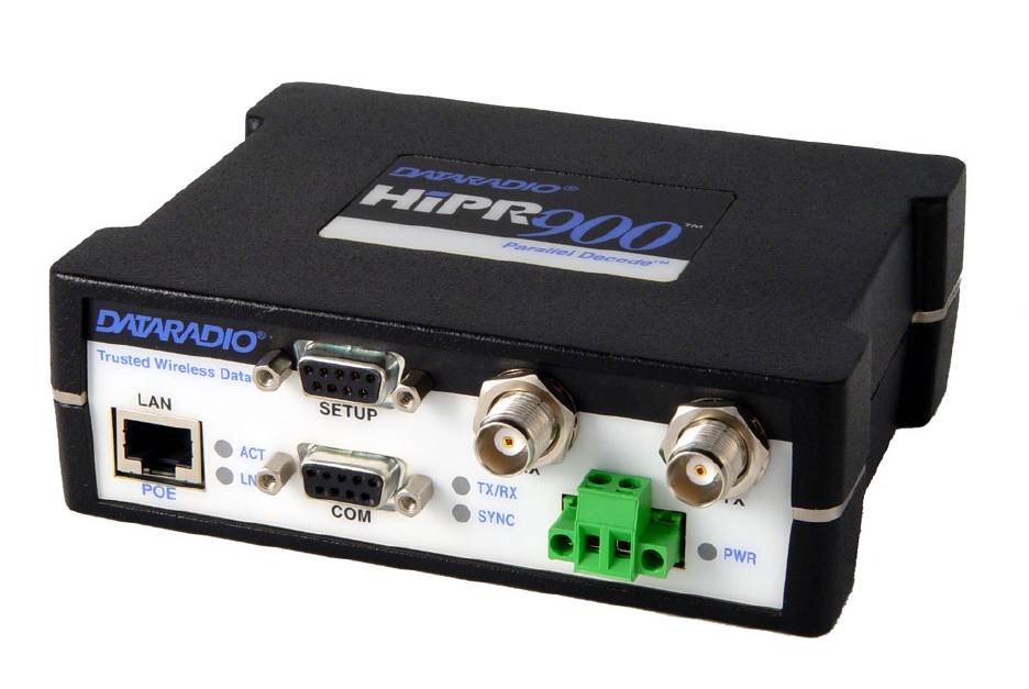
1. Product Overview
This document provides information required for the operation and preventive maintenance of the
DATARADIO® HiPR-900™ Spread Spectrum wireless modem.
1.1 Intended Audience
This manual is intended for system designers, professional installers, and maintenance technicians.
1.2 General Description
Dataradio’s HiPR-900 with Parallel Decode™ is a Frequency-Hopping Spread-Spectrum wireless radio-
modem that operates in the license free 902-928 MHz band using IP/Ethernet connectivity. HiPR-900 is
designed for SCADA, telemetry, control, and industrial applications in Point-to-Point and Point-to-
Multipoint configurations.
HiPR-900 supports both serial and Ethernet/IP Remote Terminal Units (RTU) and programmable logic
controllers (PLC). It is standard IEEE 802.3af compliant.
Figure 1 - HiPR-900
DATARADIO is a registered trademark, HiPR-900 and PARALLEL DECODE are trademarks of Dataradio Inc
120 40515-100a HiPR900 User Manual
9

The HiPR-900 wireless modem consists of a logic PCB (which includes modem circuitry) and a radio
module. Each logic PCB and radio module is constructed in the factory to optimize performance as a
wireless modem. The two boards are installed in a cast aluminum case.
The HiPR-900 wireless modem “hops” from channel to channel several times per second using a “hop”
pattern applied to the Master and Remotes in a network. A distinct hopping pattern is provided for each of
the available System IDs. This distinct pattern minimizes the chance of interference with other spread
spectrum networks. In the United States and Canada, no license is necessary to install and operate this
type of spread spectrum system.
The unit is not hermetically sealed and should be mounted in a suitable enclosure when dust and/or a cor-
rosive atmosphere are anticipated. Physically, there are no external switches or adjustments. All operating
parameters are set using web browser.
1.2.1 Characteristics
HiPR-900 has the following operational characteristics:
• High-speed user-selectable data rates of 256 and 512 Kbps and superior data compression.
• Built-in adjustable 0.1 to 1 watt transceiver.
• Used as an access point or an end point with each configurable in:
♦ Bridge mode - for fast setup between networks
♦ Router mode - for advanced networks
• Embedded web server with browser access (locally or remotely) to status or setup information.
• Remote access for over-the-air system firmware upgrades.
• Parallel Decode™ with SMART COMBINING dual receivers for added decode sensitivity in multi-
path and fading environments.
• Wide input power range of 10 to 30 volts DC and flexibility of Power over Ethernet (PoE).
• AES 128-bit data encryption
• Native UDP and TCP/IP support
• Optimized IP (OIP) protocol reduction
• Diagnostics
• Built-in Spectrum Analyzer
1.2.2 Accessories and Options
Table 1 lists various accessory items available for the HiPR-900 Wireless Modem.
Table 1 - Accessories
Accessory DRL Part Number
Cables, Power kit, Power cable TBD
Adapters, RF cables, Ethernet cables, etc… TBD
Antenna kit Contact Sales Representative
Technical manual on CD ROM TBD
For information on accessories and options, contact your sales representative. In the United States, call 1-800-992-7774 or 1-507-
833-8819. For International inquiries, call 507-833-8819.
120 40515-100a HiPR900 User Manual
10

1.2.3 Configuration
HiPR-900 units are factory-configured to default settings. Configuration changes or upgrades are web-
based.
1.3 Factory Technical Support
The Technical Support department of DATARADIO® provides customer assistance on technical prob-
lems and serves as an interface with factory repair facilities.
Dataradio COR Ltd.
299 Johnson Avenue, Suite 110
Waseca, MN 56093-0833
Technical Support hours are: Monday to Friday 7:30 AM to 4:30 PM, Central Time
Phone: 1-800-992-7774 or 1-507-833-8819 and Fax: 1-507-833-6748
Support Fax: 1-507-833-6758
Email: support@dataradio.com
1.4 Product Warranty
The HiPR-900 radiomodem is backed by Dataradio COR Ltd.'s two-year warranty excluding third party
components which are covered by their respective manufacturer's warranty.
Dataradio's Data Telemetry Product Warranty statement is in Appendix 1 and included in .pdf format on
CD versions of Dataradio technical manuals.
1.5 Replacement Parts
This product is not field-serviceable, except by the replacement of a complete unit. Specialized equipment
and training is required to repair logic boards and radio modules.
Contact Technical Support for service information before returning equipment. A Technical Support rep-
resentative may suggest a solution eliminating the need to return equipment.
1.5.1 Factory Repair
Dataradio products are designed for long life and failure-free operation. If a problem arises, factory ser-
vice is available. Contact the Technical Service Department before returning equipment. A service repre-
sentative may suggest a solution eliminating the need to return equipment.
A Return Material Authorization (RMA) number is required when returning equipment to Dataradio for
repair. Contact the Technical Service Department at 1-800-992-7774, extension 6290 to request a RMA
number. Be prepared to give the equipment model and serial number, your account number (if known),
and billing and shipping addresses.
Include the RMA number, a complete description of the problem, and the name and telephone number of
a contact person with the returned units. This information is important. The technician may have ques-
tions that need to be answered to identify the problem and repair the equipment. The RMA number helps
locate your equipment in the repair lab if there is a need to contact Dataradio concerning the equipment.
Units sent in for repair will be returned to the customer re-tuned to the current Dataradio Test and Tune
Procedure and will conform to all specifications noted in this section.
120 40515-100a HiPR900 User Manual
11
Customers are responsible for shipping charges (to Dataradio) for returned units in warranty. Units in
warranty are repaired free of charge unless there is evidence of abuse or damage beyond the terms of the
warranty. Dataradio covers return shipping costs for equipment repaired while under warranty.
Units out of warranty are subject to repair service charges. Customers are responsible for shipping
charges (to and from Dataradio) on units out of warranty. Return shipping instructions are the responsibil-
ity of the customer.
1.6 Unpacking
When ready for installation, carefully unpack your HiPR-900 shipping carton and identify each item as
listed below:
• One HiPR-900 radiomodem
• Power cable (3 ft)
• Ethernet cable (3 ft)
• Quick Start Guide
If damage has occurred to the equipment during shipment, file a claim with the carrier immediately.
120 40515-100a HiPR900 User Manual
12

2. Installation
2.1 Parallel Decode
Dataradio's proprietary patent-pending Parallel Decode(tm) technology combines Spatial Diversity and
Smart Combining to provide increased sensitivity plus immunity to multipath fading. Even in the ab-
sence of motion, the changing wavelengths inherent in frequency-hopping systems makes it possible for
stationary sites to experience frequency-selective interference. Parallel Decode technology receives and
continuously combines signals from two antennas a short distance apart, ensuring a more reliable link.
The dual antenna connections also permit the use of a higher-gain antenna for the receiver. Full 1W
transmit power can be used with up to 6 dBi antenna gain.
Dual antenna ports also permit listening to a far distant site with a high- gain antenna while using an omni
to serve local stations. The Parallel Decode receiver algorithm automatically and continually decodes sig-
nals from both antennas.
In special applications such as rotating machinery, dual antenna ports allow the use of cross-polarized
antennas, automatically selecting the best signal regardless of the orientation of the machine.
2.2 Antennae Installation
2.2.1 Professional Installation & RF Exposure Compliance Requirements
The HiPR-900 radiomodem is intended for use in the SCADA market. The HiPR-900 must be profession-
ally installed and must ensure a minimum separation distance of more than 9.06 in. (23 cm) between the
radiating structure and any person. An antenna mounted on a pole or tower is the typical installation and
in rare instances, a 1/2-wave whip antenna is used.
The HiPR-900 radiomodem uses low power radio frequency transmitter. The concentrated
energy from an antenna may pose a health hazard. People should not be in front of the an-
tenna when the transmitter is operating.
RF Exposure
The installer of this equipment must ensure the antenna is located or pointed such that it does not emit an
RF field in excess of Health Canada limits for the general population. Recommended safety guidelines for
the human exposure to radio frequency electromagnetic energy are contained in the Canadian Safety
Code 6 (available from Health Canada) and the Federal Communications Commission (FCC) Bulletin 65.
Proper installation of the transceiver antenna of HiPR-900 products, as summarized in section 2.2.2 be-
low, will result in user exposure substantially below the recommended limits for the general public.
The HiPR-900 complies with Part 15 of the FCC rules and must be professionally installed. Operation
must conform to the following two conditions:
• This device may not cause harmful interference.
• This device must accept any interference received including interference that may cause unde-
sired operation of the device.
Notes: Any changes or modifications not expressly approved by the party responsible for com-
pliance (in the country where used) could void the user's authority to operate the equip-
ment.
120 40515-100a HiPR900 User Manual
13
2.2.2 Antenna Connection
This equipment has been tested and approved with antennae having a maximum gain of 8.5 dB. Antenna
with a higher gain are strictly prohibited (regulations of Industry Canada). The required antenna imped-
ance is 50 ohms. To reduce potential radio interference, the antenna type and its gain should be chosen to
ensure the effective isotropic radiated power (EIRP) is not more than required for successful communica-
tion.
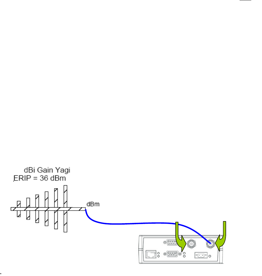
FCC/IC Rule: The output power is not to exceed 1.0 watt (30 dBm) and the EIRP not to exceed 6 dBi
gain (36dBm). A sample calculation is provided below.
Referring to Figure 2:
Sample Calculation: Yagi Antenna: 8.5 dBi, which exceeds 6 dBi gain by 2.5 dB
Cable Loss: 1.5 dB
HiPR-900 output initially set to 30 dBm (1 watt).
(Initial output level) dBm - (excess antenna gain) dB + (cable loss) dB = (new power setting) dBm
Therefore, the sample calculation becomes: 30dBm – 2.5 dB + 1.5dB = 29 dBm
The HiPR-900 output must be reduced by 1 dB to 29 dBm.
29 dBm
“T” = TX/RX
“R” = RX
27.5
8.5
Figure 2 - Sample equation
2.2.3 Spacing and Constraints
Referring to Figure 3, HiPR-900 radiomodems commonly use two separate antennae:
• “T” - Main transceiver -
Constraints are the limit of 9.06 in/23 cm (see 2.2.1 above) and omni-directional factors
• “R” - Auxiliary receiver –
Constraints are the receiver spacing of at least 5/8 λ (wavelength) from transceiver antenna and omni-
directional requirements (8in. / 21cm)
For the optimum antenna spacing at the frequency you are using, consult Dataradio System Engineering.
120 40515-100a HiPR900 User Manual
14
For installation of ground-plane dependent antennas, the center of the surface used for mounting is pref-
erable for best omni-directional pattern. For ground-plane independent antennas, installation may be close
to the edges of the mounting surface.
R
T
37cm
14.58in.
≥5/8λ
900MHz: 8”/21cm)
Figure 3 - Antenna spacing
2.2.4 Acceptable Antennae
The antennae listed in Table 2 were tested and typed for maximum gain. These antennae are FCC ap-
proved for use with the HiPR-900. Similar antenna types from other manufacturers are also acceptable.
Table 2 - Acceptable Antennae
Type Manufacturer Part Number Gain (dBi)
Yagi Maxrad BMOY8903 8.5
Omni Directional Maxrad MFB9153 5.1
Directional Panel Maxrad MP8066 8.1
Portable Maxrad MEXR-902-BN 2.5
2.3 Network application
HiPR-900 is suited to a variety of network applications. Its primary design goal was to satisfy the needs
of SCADA systems using RTUs or PLCs in either point-to-point or point-to-multipoint service. This sec-
tion gives an overview of some common configurations.
2.3.1 Modes
2.3.1.1 Bridge mode
Bridge mode provides for fast set-up. IP bridging for quick deployment of basic point-to-point and point-
multipoint networks with minimal configuration. Bridge mode carries ARP and is transparent to any IP-
based or IP-encapsulated protocols.
2.3.1.2 Router mode
Used in advanced networks, router mode enables OIP optimization for reduced overhead and improved
throughput, and supports more complex network topologies such as store-and- forward and multihop
links. There is only one model to buy or stock because any HiPR900 unit can be configured for bridge or
router mode, router gateway (access point), remote station, or even as a combined store-and-forward re-
mote with a local drop.
120 40515-100a HiPR900 User Manual
15
Selection of “master” or “remote” as well as data delivery conditions is done using the web browser.
2.3.2 RF Path and communications range
The reliable communication range of the HiPR-900 is dependent on terrain, RF (radio frequency) path
obstacles, and antenna system. To assure reliable communications, a competent professional who can de-
termine what antennae are required and whether or not a repeater is needed should study the RF path be-
tween stations.
2.3.3 COMMON CHARACTERISTICS
The networks described in this section share common characteristics:
1. The network speed (256 and 512 Kbps) varies in a network as the Master announces the speed to
use to the remote stations.
2. Transmission of online diagnostics may be enabled or disabled at any station or stations without af-
fecting their ability to communicate with other stations.
2.3.4 Basic connections
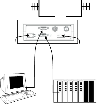
The connections required are shown in Figure 4.
While an RTU or PLC is shown in the diagram, master stations often use a PC running an application de-
signed to communicate with remote RTUs or PLCs. The Setup PC is used for both configuration and local
and remote diagnostics. It may be left connected at all times but is not required for normal operation once
the unit has been configured.
Figure 4 - Basic Setup
User’s
RTU or PLC
PD
Antenna
10-30 VDC
PoE
Antenna
Setup PC
2.3.5 POINT-TO-POINT SYSTEM
120 40515-100a HiPR900 User Manual
16
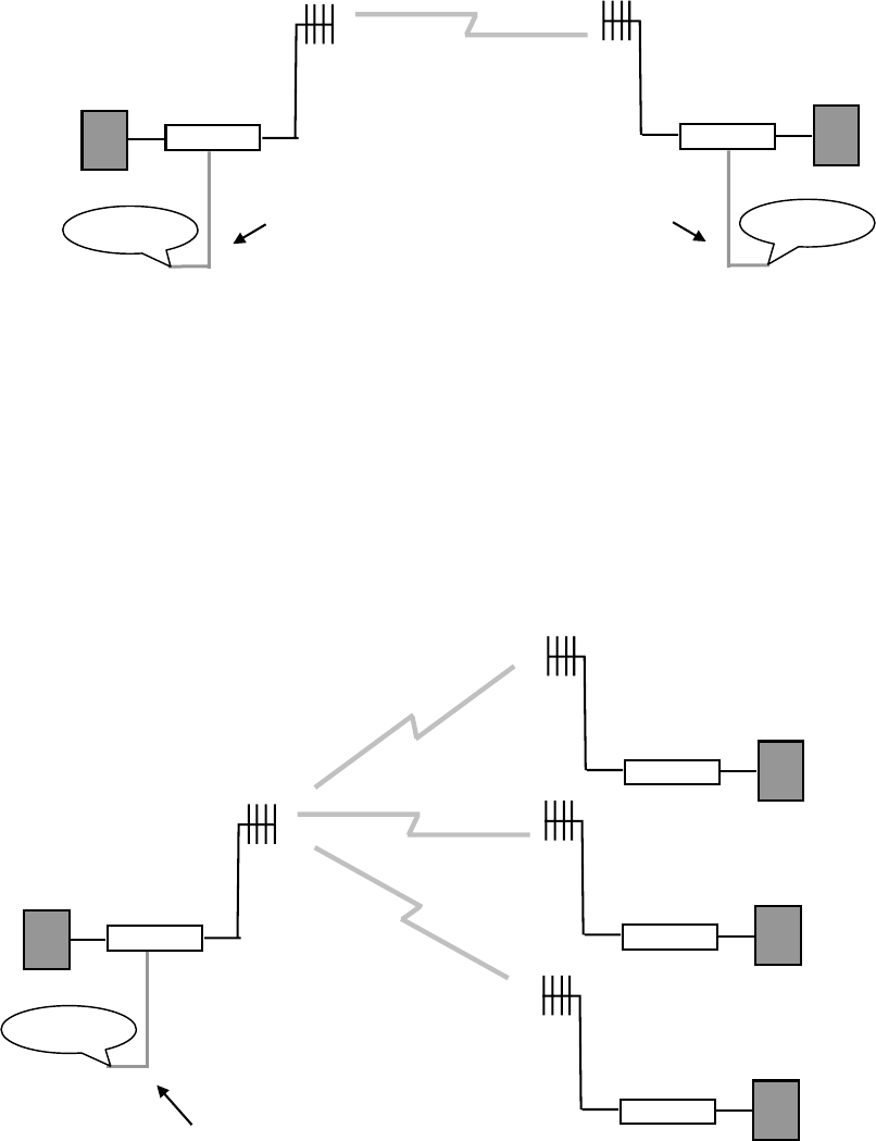
Figure 5 - Point-to-Point IP Network System
HiPR-900 HiPR-900
DTE DTE
Bridge Mode (Ethernet) connections possible Network
Network
A simple point-to-point connection is shown above. In this system, the user's equipment (DTE) is set up
in a master-remote configuration. Ethernet network connection is also possible using bridge mode.
2.3.6 POINT-MULTIPOINT SYSTEM
Figure 6 - Point-to-Multipoint System
HiPR-900
HiPR-900
Remote
Remote
Remote
HiPR-900
HiPR-900
Master
Network
Bridge Mode (Ethernet) connections
possible
A basic Point-Multipoint system for polling application is shown above. Using a web browser, one HiPR-
900 unit must be set to “Master”. The remaining units in the network must be set to “Remote”. All units
are set to “selective” data delivery to prevent remote stations from hearing each other's responses.
Ethernet network connection is also possible using bridge mode.
120 40515-100a HiPR900 User Manual
17
2.4 Selectable Data Rates
Switchable data rates of 256 and 512 Kbps allow optimizing installations for highest throughput or
maximum range. The sophisticated DSP modem gives optimal performance in either mode, whether a
short-range LAN extension or long-range point-to-point link.
2.5 Combined Access Point and Remote
Any unit can be configured as a Master station, and as an Access Point or Remote. This flexibility allows
the backbone network to be connected wherever it is most convenient, and completely independently of
where the Master station is located. Deployment and keeping spares is simplified with only a single
model required.
2.6 Online & Offline Diagnostics
HiPR-900 units continually monitor and report on their environmental and operating conditions. Each
transmission carries online diagnostic information that can be monitored remotely or even sent to a desig-
nated host for logging and later analysis.
Additional information, statistics, and offline test facilities are available via the browser. RF paths can be
monitored and checked from either end of a link, without travelling to the other station.
2.7 Built-in Spectrum Analyzer
Dataradio's innovative built-in Spectrum Analyzer continually monitors signal strength at each unit dur-
ing normal operation. The spectrum analyzer can also scan the band on command to establish the noise
floor and check for foreign signals or other sources of interference. Noisy or occupied sub-bands can be
locked-out.
120 40515-100a HiPR900 User Manual
18

3. Physical Description
3.1 Front Panel
PWR
SYNC
LNK
ACT
+ -
RX / TX
RX
TX/RX
DATA
SETUP
POE
LAN
Figure 7 - HiPR-900 Front Panel
The front panel includes:
• One standard RJ-45 autosensing 10/100 UTP Ethernet connection with Auto-MDIX. Supports di-
rect connection to both Terminal Devices and Ethernet hubs or switches without resorting to
crossover cables. LED indicators make it simple to verify that Ethernet cables and connections
are good.
• Two DE-9F RS232 ports. Serial baud rates from 1200 to 115,200 are supported. The HiPR-900
radiomodem is factory set (default) for 19200 b/s, 8 bits, no parity, and 1 stop bit.
• The antenna connector for the transceiver is a female 50-ohm TNC type. The HiPR-900 is de-
signed to operate with an antenna having a maximum gain of 10 dBi. Antennae with higher gain
are strictly prohibited (FCC and Industry Canada). Required antenna impedance is 50 ohms.
• One TNC-type female antenna connector for the auxiliary receiver
• One right-angle power connector. The 10 to 30 VDC wide-range switching power supply permits
powering from 12 volt as well as 24 volt systems, and the high-efficiency switching design runs
cooler with less loss. The HiPR-900 automatically senses and switches between its DC input and
PoE, using the DC input if both are present. This minimizes the load on PoE Ethernet switches
while allowing them to act as a backup to the local power supply.
• HiPR-900 has five dual-color LED indicators. Their functions are shown in Table 3.
Table 3 - HiPR-900 LEDs indications
LED Color Definition
ACT Green Data transmission or reception activity
Green Connection OK
LINK Amber Collision
Green Data reception activity
Amber Data transmission activity
Tx / Rx
Red Receive CRC error
Remote: In sync with Master
Green Master: Normal
Remote: Loss of Master sync
SYNC Red Master: Failure
Green Normal
Amber (at boot-up) Normal (approx 5 secs)
Amber Application failure
PWR
Red Hardware failure
120 40515-100a HiPR900 User Manual
19
120 40515-100a HiPR900 User Manual
20
4. Operation & Configuration
4.1 Local and Remote (OTA) Configuration
Configuration and status displays are accessible from anywhere on the network, wired, or wire-
less. Monitoring, problem diagnosis, and even configuration changes can be done from anywhere
on the corporate network. Setup is password-protected to avoid tampering or unauthorized
changes.
4.2 Over-the-Air Firmware Upgrade
Both the configuration parameters and operating firmware can be updated remotely, even over the
network itself, using the standard FTP protocol.
4.3 Browser-Based Setup and Status
A built-in web server makes configuration and status monitoring possible from any browser-
equipped computer, both locally or remotely. Status, configuration, and even online help are
available without requiring special client software. Connect to any unit from any other, or over
corporate LAN.
4.3.1 LAN Setup
On a laptop or a desktop PC running MS-Windows and equipped with an existing LAN connec-
tion, connect to the RJ-45 input of the HiPR-900.
1. Click Start Î Settings Î Control Panel Î Network and Dial-up Connection
2. Click on the relevant Local Area Connection
3. On the Local Area Connection Status screen, click the Properties button
4. On the Local Area Connection Properties screen, scroll the List Box until “Internet Protocol
(TCP/IP)” is highlighted, click the Properties button
5. On the Internet Protocol (TCP/IP) Properties screen, select the “Obtain an IP address auto-
matically” radio button
Note:
If selecting instead the “Use the following IP address” radio button, enter
192.168.204.nnn (where nnn is a number between 2 and 254) in the IP address field. The
Subnet mask is 255.255.255.0 while the Default gateway is left blank.
6. Click the OK button
7. Reboot to complete the connection process
4.3.2 Login Screen
On the Address line of the Internet browser of your choice, type the factory-default IP address
given to all HiPR-900 radiomodem units: 192.168.204.1. Press Enter. The Enter Network Pass-
word screen opens.
120 40515-100a HiPR900 User Manual
21
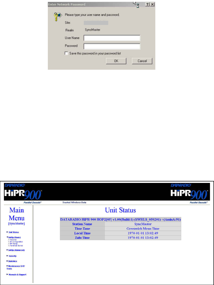
192.168.204.1
Figure 8 - Enter Network Password screen
4.3.2.1 Initial Installation Login
For an initial installation, type in the User Name dialog box a string of any letters or numbers of
at least 1 and not exceeding 15 characters. Type in the Password dialog box a string of any letters
or numbers of at least 8 and not exceeding 15 characters. Do not place a check mark in the “Save
this password in your password list” box. Click OK to access to the Web Interface (Figure 9).
Dataradio recommends immediately changing the HiPR-900 unit’s IP address as well as set your
own login password as part of the initial configuration (See 4.3.3.4 and 4.3.3.13).
For subsequent access to the HiPR-900 unit, use the User Name and Password you configured.
Note:
The User Name entry is currently not an access-limiting factor. It only serves to identify
the person gaining access. User Name may be required by future versions.
Figure 9 - Web User Interface (Preliminary)
120 40515-100a HiPR900 User Manual
22
4.3.3 Interface
The HiPR-900 user interface (Figure 9) provides easy access to the various menus used to con-
figure and view your network settings.
The Navigation Area lists seven top-level menus, four of which expand to offer submenu. The
tables starting at section 4.3.3.2 below list action of each function.
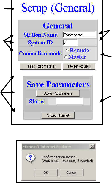
4.3.3.1 Test & Save Parameters Buttons Behavior
Submenus which have Dialog boxes also have Command Buttons to Test, Reset, and Save Pa-
rameters in addition to Station Reset.
Referring to the example in Figure 10 below, make entries into the Dialog boxes. When satisfied,
click on Test Parameter to temporarily make the parameters active in the unit’s memory. If not
satisfied, click on Reset values button to return to the status prevalent before changes were made.
Notes:
Reset values commands affect all Dialog boxes or radio buttons in the opened window.
When finished, permanently save the parameter entries into the unit’s memory (along with any
other entries made in other submenus); click on Save Parameters.
Some parameters require a Station Reset and the Station Reset command button only appears if
needed. Use the Save Parameters command button before Station Reset otherwise temporarily
entered parameters are lost. Pressing the Station Reset button opens the Confirm Station Reset
(Figure 11) as a reminder to first save.
Figure 10 - Parameter Command Buttons behavior
Commands
Submenu
Command
Buttons
Radio
Buttons
Dialog
Boxes
Read-only
Box
Figure 11 - Station Reset Confirmation
120 40515-100a HiPR900 User Manual
23

4.3.3.2 Unit Status
Table 4 - Unit Status
Command Description
Banner Displays HiPR-900 information retrieved from the connected unit. Have
this information handy if contacting Dataradio support.
Station Name Displays name of connected unit.
Configured under Setup Basic Î General Î StationID
Time Zone Displays local time zone.
Configured under Setup Advanced Î SNTPÎ TimeZone
Local Time Displays local time computed using UTC time and Time Zone
Zulu Time Displays UTC time.
Configured under Setup Advanced Î SNTPÎ SNTP UTC Time
4.3.3.3 Setup (General)
Table 5 - Setup (General)
Command Description
Station Name Station name identifier – Enter string up to forty characters in length
System ID Factory default ID is zero. Dataradio recommends changing it to some
other value unique to each HiPR-900 network to prevent collision and
security reason.
Connection mode
Remote/Master
Within a HiPR network, one unit has to be configured as a master that
the remotes synchronize to. It can be any unit in a system but is nor-
mally the one considered the base unit for coverage and support rea-
sons.
IP Forwarding mode Bridge / Router modes – Defaults to Bridge mode. Use Router for more
advanced IP configurations.
4.3.3.4 Basic IP Configuration
Table 6 - Basic IP Configuration
Command Description
IP Address Set to valid unique IP address for each individual unit
Network Mask Set to valid IP netmask for each individual unit (may be same or differ-
ent depending on customer’s IP network topology).
IP Default Gateway Set to valid Default Gateway.
May change for different groups or locations
4.3.3.5 RF Setup
Table 7 - RF Setup
Command Description
Power Level Sets power level between 0.1 and 1.0 watt (Default 1.0)
Airlink speed 256000, 512000 (Default) - Sets the maximum speed the HiPR900 will
use for data packet transmissions. Slower speed preferred for longer
range.
SubBand Mask Indicates which channels are to be used in the shared band.
120 40515-100a HiPR900 User Manual
24

4.3.3.6 Terminal Server Configuration
Table 8 - Terminal Server Configuration
Command Description
Port 1 - 2400, 4800, 9600, 19200, 38400, 57600, 115200
Baud Rate Port 2 - 2400, 4800, 9600, 19200, 38400, 57600, 115200
Port 1 - Inactive, TCP Passive, TCP Active, UDP
Connection Mode Port 2 - Inactive, TCP Passive, TCP Active, UDP
Local Port
Remote IP Address
Remote Port
4.3.3.7 Advanced IP Configuration
Table 9 - Advanced IP Configuration
Command Description
MTU Default 1500. Range 576 to 1500 bytes
Factory MAC address Factory Ethernet MAC address
DHCP Server Disabled, Enabled (Default).
DHCP Client Disabled(Default), Enabled
NAT Disabled(Default), Enabled
RIPV2 Disabled(Default), Enabled
4.3.3.8 RF Network Setup
Table 10 - RF Network Setup
Command Description
RF MAC Unit’s RF MAC address
Displays factory-assigned address: nnn.nnn.nnn.nnn “Factory”
RF IP Address Entering 0.0.0.0 sets the RF IP Address to the factory default and high-
lights the “Factory” name (active address)
Entering nnn.nnn.nnn.nnn (RF IP Address of your choice) overrides the
factory default and highlights the “Override” name (active address)
RF Net Mask Set to valid common IP netmask for all units within a HiPR network
RF MTU Default 1500. Range 576 to 1500 bytes
4.3.3.9 Broadcast / Multicast
Table 11 - Broadcast / Multicast
Command Description
Broadcast Outbound mobile address
Broadcast Directed Enable Disabled, Enabled
Broadcast Limited Enable Disabled, Enabled
Multicast Addresses
Multicast Add / Delete Address Add, Delete and Relevant address
Multicast Enable Disabled, Enabled
120 40515-100a HiPR900 User Manual
25
Local IP Address

4.3.3.10 IP Optimization & Tuning
Table 12 - IP Optimization & Tuning
Command Description
Optimization TCP Proxy Disabled (Default), Enabled. Actives the TCP Proxy module
Optimization Data Compression Disabled, Enabled (Default). Applies data compression over the IP pay-
load
OIP RF ACK enable Disabled (Default), Enabled.
OIP Retries Enter number of retries. Default is 3, range 0-255
4.3.3.11 Simple Network Time Protocol
Table 13 - Simple Network Time Protocol
Command Description
SNTP – Server addr
SNTP – Enable Disabled, Enabled
SNTP – Period
SNTP – UTC Time
SNTP – TimeZone
SNTP – Daylight Savings Off, On
Time Control – Time Sources AirLink, SNTP
Time Control Refresh Period
Time Control Refresh TimeOut
4.3.3.12 Hopper Network
Table 14 - Hopper Network
Command Description
Dwell Displays value between 10 and 400ms
Sync Loss
Displays value between 50 and 10000ms. Indicates time a remote unit
will stop transmitting after the master is 'lost'.
Value usually at least several times the current dwell cycle time
Max Net Speed 256000, 512000(Default)
TDD Mode
Off, On( Default) –
Normally used in a point- to- point network carrying Ethernet traffic.
Maximizes RF link efficiency for bridges carrying two-way traffic
ACK Mode Off, On
SubBand Mask
4.3.3.13 Security
Table 15 - Security
Command Description
User ID Enter a string of any letters or numbers of at least 1 and not exceeding
15 characters
Old Password For initial installation, enter a string of any letters or numbers of at least
8 and not exceeding 15 characters. For subsequent access, enter the
old password.
120 40515-100a HiPR900 User Manual
26

New Password Enter a string of any letters or numbers of at least 8 and not exceeding
15 characters
New Password Re-enter the new password string
Encryption Disabled, Enabled
Encryption Key
All units in a network must have the same key. Enter a string of 32
(16bytes = 128 bits) hexadecimal characters (0 to F).
Displayed in pairs separated with spaces
4.3.3.14 Network Statistics
Table 16 - Network
Command Description
Data bytes presented
Control Acks Rx’d
Data packets sent
Data bytes delivered
Control Nacks Rx’d
Data packets Rx’d
4.3.3.15 Packet Statistics
Table 17 - Packet Statistics
Command Description
RX: Total packets received
RX: Total bytes received
RX: Packets
RX: Packets delivered
RX: Packets forwarded
RX: Packets miss
RX: Packets discard
RX: Packets Error
TX: Packets
TX: Packets miss
TX: Packets discard
TX: Packets Error
RX: Packets missed
RX: Erroneous packets
RX: Discarded packets
TX: Total packets sent
TX: Total bytes
TX: Packets missed
TX: Erroneous packets
IP Stats
TX: Discarded packets
RX: Total packets received
RX: Packets missed
RX: Erroneous packets
UDP Stats
RX: Discarded packets
120 40515-100a HiPR900 User Manual
27

TX: Total packets sent
TX: Packets missed
TX: Erroneous packets
TX: Discarded packets
RX: Total packets received
RX: Packets missed
RX: Erroneous packets
RX: Discarded packets
TX: Total packets
RX: Packets missed
RX: Erroneous packets
RX: Discarded packets
TCP Socket Active Connection
TCP Socket Passive Connection
TCP Socket Open Connection
TCP Socket Close Connection
TCP Socket Reset Connection
TCP Socket Failed Connection
TCP Stats
TCP Socket Abort Connection
RX: Total packets received
RX: Packets missed
RX: Erroneous packets
RX: Discarded packets
TX: Packets
RX: Packets missed
RX: Erroneous packets
ICMP Stats
RX: Discarded packets
4.3.3.16 Event Log
Table 18 - Event Log
Command Description
Event Log
4.3.3.17 RF Test
Table 19 - RF Test
Command Description
Ping
Test Tones
4.3.3.18 FTP Transfer
Table 20 - FTP Transfer
Command Description
Server Address
User Name
120 40515-100a HiPR900 User Manual
28

Password
File Name
Operation Send (Put), Receive (Get)
Mode ASCII, Binary
Request Transfer
Reset values
Status
4.3.3.19 RSSI Table
Table 21 - RSSI Table
Command Description
RSSI meters (dBm) See Figure nn
Range
Thresholds
4.3.3.20 Manuals & Support
Table 22 - Manuals & Support
Command Description
Manuals
120 40515-100a HiPR900 User Manual
29
5. Troubleshooting & Testing
5.1 Hardware Requirements
• In-line watt meter (5W range)
• Radio service monitor (IFR or equivalent).
• Cable with TNC male connector to connect HiPR-900 to the service monitor.
5.2 Software Requirements
5.2.1 Ping
The PING command determines whether a specific IP address is accessible. It works by sending a
packet to the specified address and waiting for a reply. It is useful for troubleshooting “end-to-
end” reachability, network connectivity, and network latency.
5.2.2 HiPR-900 Web interface
5.2.2.1 RF and IP Information
See web interface Setup pages, which includes RF and IP information
5.2.2.2 Status and Statistics
See web interface Statistics page, which includes Network and Packet statistics
5.2.2.3 RF Tests
See web interface Maintenance & RF Tests page, which includes RF Tests
5.2.3 Windows/Unix Tools
5.2.3.1 Network Connectivity
• PING
• ROUTETRACE (UNIX) / TRACERT (WINDOWS)
5.2.3.2 Configuration Information
• WINIPCFG (WIN95/98), IPCONFIG (WIN2K) or IFCONFIG (UNIX) - To view
system TCP/IP setting.
• DHCPMGR (UNIX) - Graphical user interface which enables user to manage the
DHCP service on the local system
• ARP (WINS & UNIX) View and update the system ARP table
• ROUTE (WINS & UNIX) View and update the system routing table
5.2.3.3 Statistics Information
• NETSTAT (WINS & UNIX) The netstat command symbolically displays the con-
tents of various network-related data structures, i.e. IP, TCP UDP …
120 40515-100a HiPR900 User Manual
30
5.2.3.4 DNS
To Troubleshoot DNS specific problem.
• NSLOOKUP - Program to query Internet domain name servers.
• WHOIS - Utility that returns information about a domain name or IP address.
For example, if you enter a domain name such as www.dataradio.com, whois
will return the name and address of the domain's owner.
• Finger - Utility that takes an email address as input and returns information about the
user who owns that email address . On some systems, finger only reports whether the
user is currently logged on.
120 40515-100a HiPR900 User Manual
31

6. Specifications
These specifications are subject to change without notice.
GENERAL
HiPR-900
Frequency 902- 928 MHz ISM band
Configurations IP Bridge, IP Gateway, IP Remote
Management HTTP embedded web server for setup and help
Supported Protocols Ethernet IEEE 802.3 (Any protocol running over IP such as ICMP, IGMP, TCP,
UDP,IPSec, SNTP etc.)
IP Fragmentation
Address Resolution Protocol (ARP)
IP directed broadcast
IP limited broadcast
IP multicast relay
DHCP Client and Server
Network Address Translation (NAT)
Dynamic Routing (RIPv2)
Channels 51
Channel Spacing 500 kHz
Operating Temperature -30° to + 60° C
Humidity 95% at 40° C non-condensing
Supply voltage 10 - 30 VDC maximum or IEEE 802.3af Power-Over-Ethernet (PoE)
Rx Current Drain at 12 VDC <400 mA (to be determined)
Tx Current Drain at 12 VDC <1.5 A (to be determined)
Cold start 1 8 seconds (typical)
Nominal Dimensions 5.50" W x 1.81" H x 4.25" D (13.97 x 4.6 x 10.8 cm)
Shipping Weight 2.26 lbs. (1.028 Kg)
Mounting Options Flat surface, DIN-rail option
TRANSMITTER
TX Frequencies 902- 928 MHz
Mode Frequency-hopping spread-spectrum (FHSS)
TX Power Out 0.1 to 1.0 Watts, user adjustable
Frequency Tolerance 1.0 PPM
RECEIVER
RX Frequencies 902- 928 MHz
Bit Error Rate (BER) TBD
120 40515-100a HiPR900 User Manual
32

Modem / Logic
Data Rate 256/512 Kbps (user selectable)
Modulation Type RCFSK
Addressing IP
SETUP and COM Port
Interface EIA RS-232F DE9F
Data Rate 1200 – 115,200 b/s (Defaults: Setup & COM = 19.2 Kbps)
Display
5 Bi-color status LEDs LAN link, LAN activity, Tx/Rx, Sync, Power
Connectors
Antenna Connector Dual TNC female
Serial Setup Port DE-9F
Serial Terminal Server DE-9F
Ethernet RJ-45 10/100 BaseT auto-MDIX
Power -I/O Phoenix
Diagnostics
Online temperature, Supply voltage and source, RSSI, Spectrum, fwd and rev power, back-
ground interference,
FCC / IC / UL Certifications
FCC IC (DOC) UL
900 MHz Part 15.247 pending
Pending
120 40515-100a HiPR900 User Manual
33

Appendix 1 - Data Telemetry Warranty
Dataradio COR Ltd. ("DRL") warrants to the original purchaser for use ("Buyer") that data telemetry products manufactured
by DRL ("Products") are free from defects in material and workmanship and will conform to DRL's published technical
specifications for a period of, except as noted below, two (2) years from the date of shipment to Buyer. DRL makes no war-
ranty with respect to any equipment not manufactured by DRL, and any such equipment shall carry the original equipment
manufacturer's warranty only. DRL further makes no warranty as to and specifically disclaims liability for, availability,
range, coverage, grade of service or operation of the repeater system provided by the carrier or repeater operator. Any return
shipping charges for third party equipment to their respective repair facilities are chargeable and will be passed on to the
Buyer.
If any Product fails to meet the warranty set forth above during the applicable warranty period and is returned to a location
designated by DRL. DRL, at its option, shall either repair or replace such defective Product, directly or through an authorized
service agent, within thirty (30) days of receipt of same. No Products may be returned without prior authorization from DRL.
Any repaired or replaced Products shall be warranted for the remainder of the original warranty period. Buyer shall pay all
shipping charges, handling charges, fees and duties for returning defective Products to DRL or DRL's authorized service
agent. DRL will pay the return shipping charges if the Product is repaired or replaced under warranty, exclusive of fees and
duties. Repair or replacement of defective Products as set forth in this paragraph fulfills any and all warranty obligations on
the part of DRL.
This warranty is void and DRL shall not be obligated to replace or repair any Products if (i) the Product has been used in
other than its normal and customary manner; (ii) the Product has been subject to misuse, accident, neglect or damage or has
been used other than with DRL approved accessories and equipment; (iii) unauthorized alteration or repairs have been made
or unapproved parts have been used in or with the Product; or (iv) Buyer failed to notify DRL or DRL's authorized service
agent of the defect during the applicable warranty period. DRL is the final arbiter of such claims.
THE AFORESAID WARRANTIES ARE IN LIEU OF ALL OTHER WARRANTIES, EXPRESSED AND IMPLIED,
INCLUDING BUT NOT LIMITED TO, ANY IMPLIED WARRANTY OF MERCHANTABILITY OR FITNESS FOR A
PARTICULAR PURPOSE. DRL AND BUYER AGREE THAT BUYER'S EXCLUSIVE REMEDY FOR ANY BREACH
OF ANY OF SAID WARRANTIES IT AS SET FORTH ABOVE. BUYER AGREES THAT IN NO EVENT SHALL
DRL BE LIABLE FOR INCIDENTAL, CONSEQUENTIAL, SPECIAL, INDIRECT OR EXEMPLARY DAMAGES
WHETHER ON THE BASIS OF NEGLIGENCE, STRICT LIABILITY OR OTHERWISE. The purpose of the exclusive
remedies set forth above shall be to provide Buyer with repair or replacement of non-complying Products in the manner pro-
vided above. These exclusive remedies shall not be deemed to have failed of their essential purpose so long as DRL is willing
and able to repair or replace non-complying Products in the manner set forth above.
This warranty applies to all Products sold worldwide.
Some states do not allow limitations on implied warranties so the above limitations may not be applicable. You may
also have other rights which vary from state to state.
EXCEPTIONS
ONE YEAR: Labor to replace defective parts in repeaters or base stations
THIRTY DAY: Tuning and adjustment of telemetry radios
NO WARRANTY: Fuses, lamps and other expendable parts
Effective 01/2004
Dataradio COR Ltd. 299 Johnson Avenue, P.O. Box 1733, Waseca, MN 56093-0833: Tel: (507) 833-8819 or (800) 992-7774; Fax: (507) 833-6748 Visit us on the web at
www.dataradio.com
120 40515-100a HiPR900 User Manual
34

DATARADIO is a registered trademark, HiPR-900 and PARALLEL DECODE are trademarks of
Dataradio Inc
120 40515-100a HiPR900 User Manual
35