CalAmp Wireless Networks 2422110610 Synthesized Telemetry Module User Manual Cover
CalAmp Wireless Networks Corporation Synthesized Telemetry Module Cover
UserManual.wiki
>
CalAmp Wireless Networks
>
2422110610 User Manual
manual
Navigation menu
Upload a User Manual
Namespaces
Wiki Guide
HTML
PDF
Info
Views
User Manual
Discussion / Help
Navigation


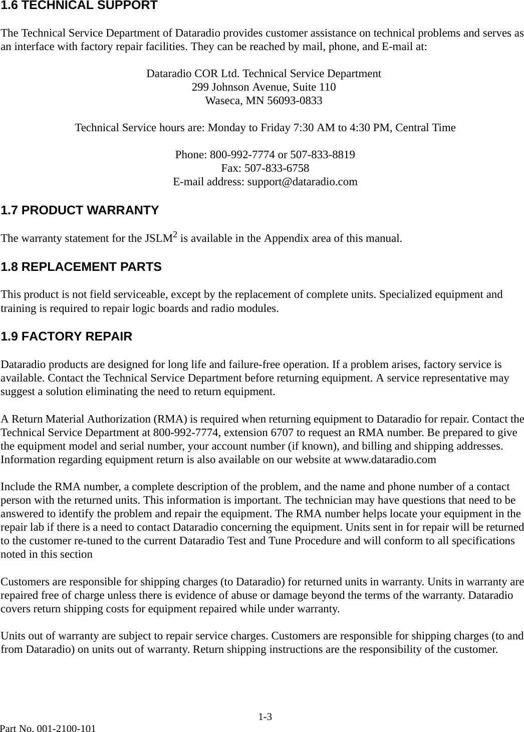
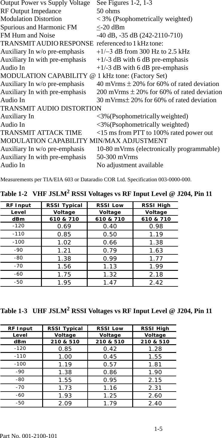
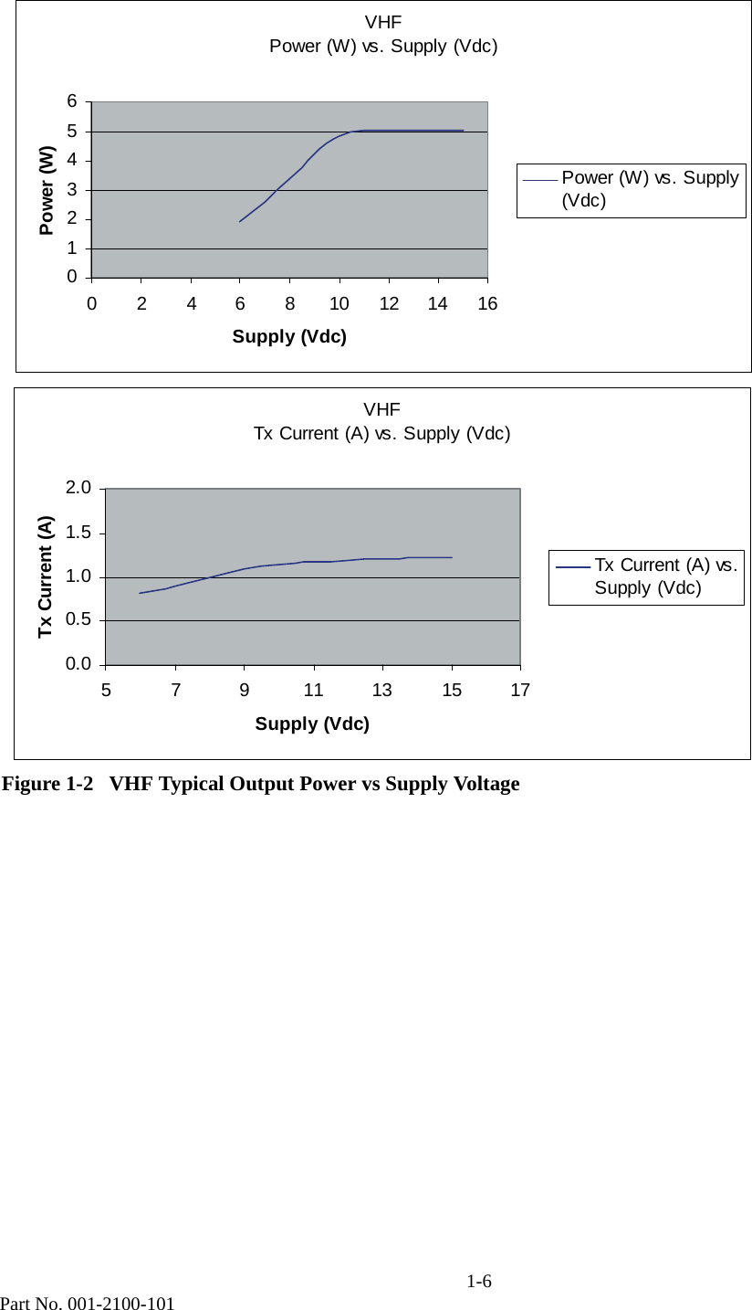
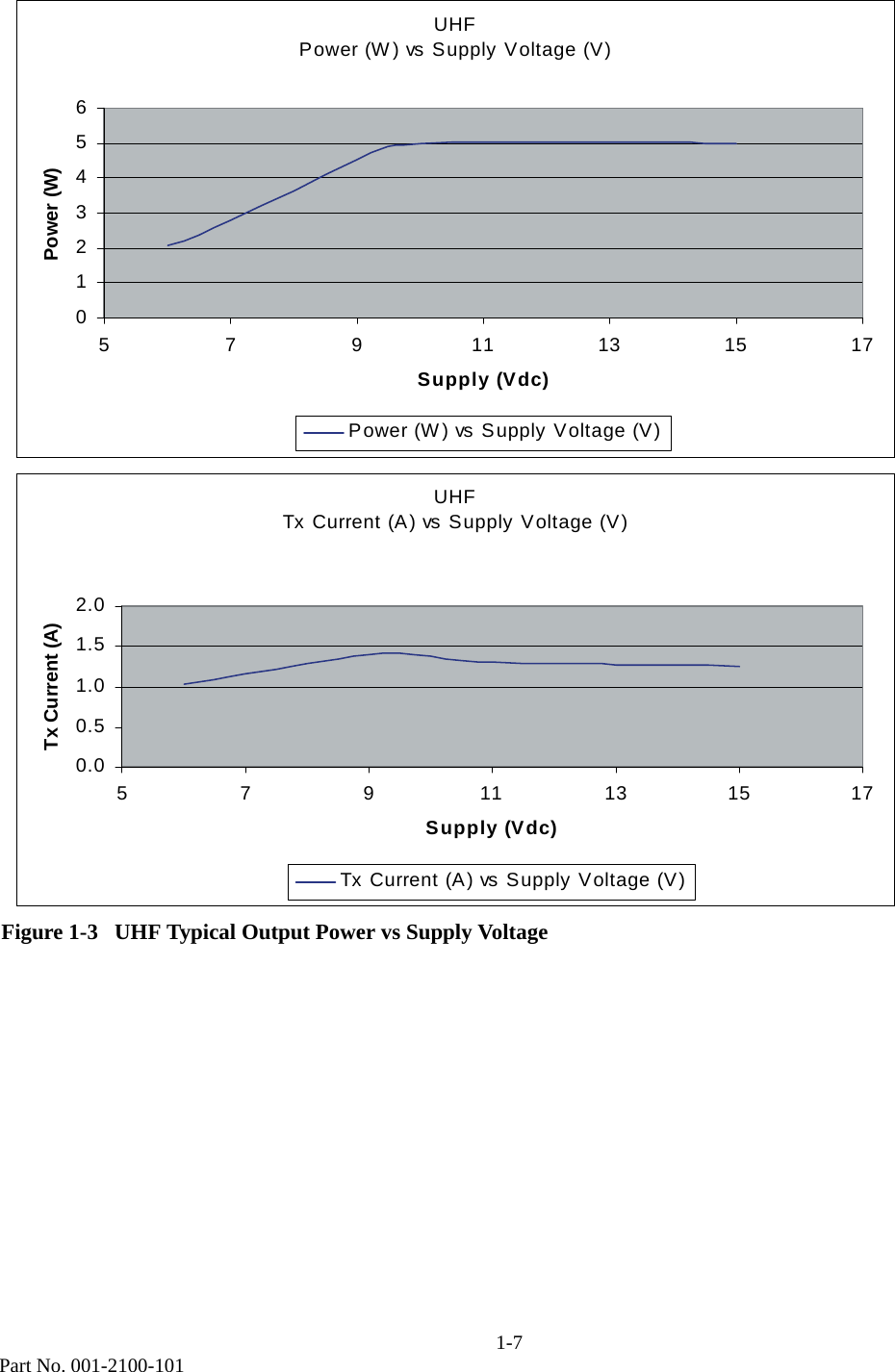
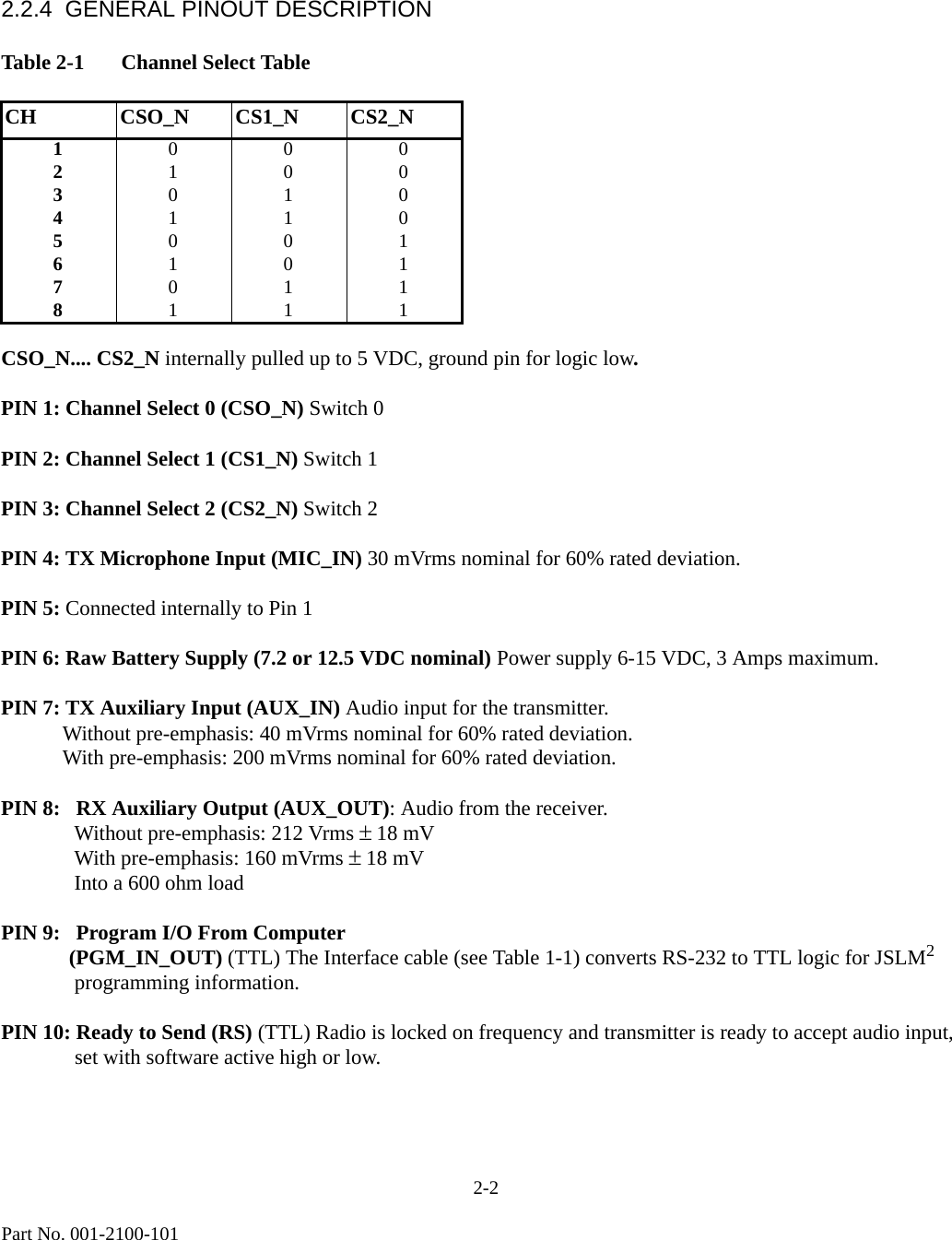
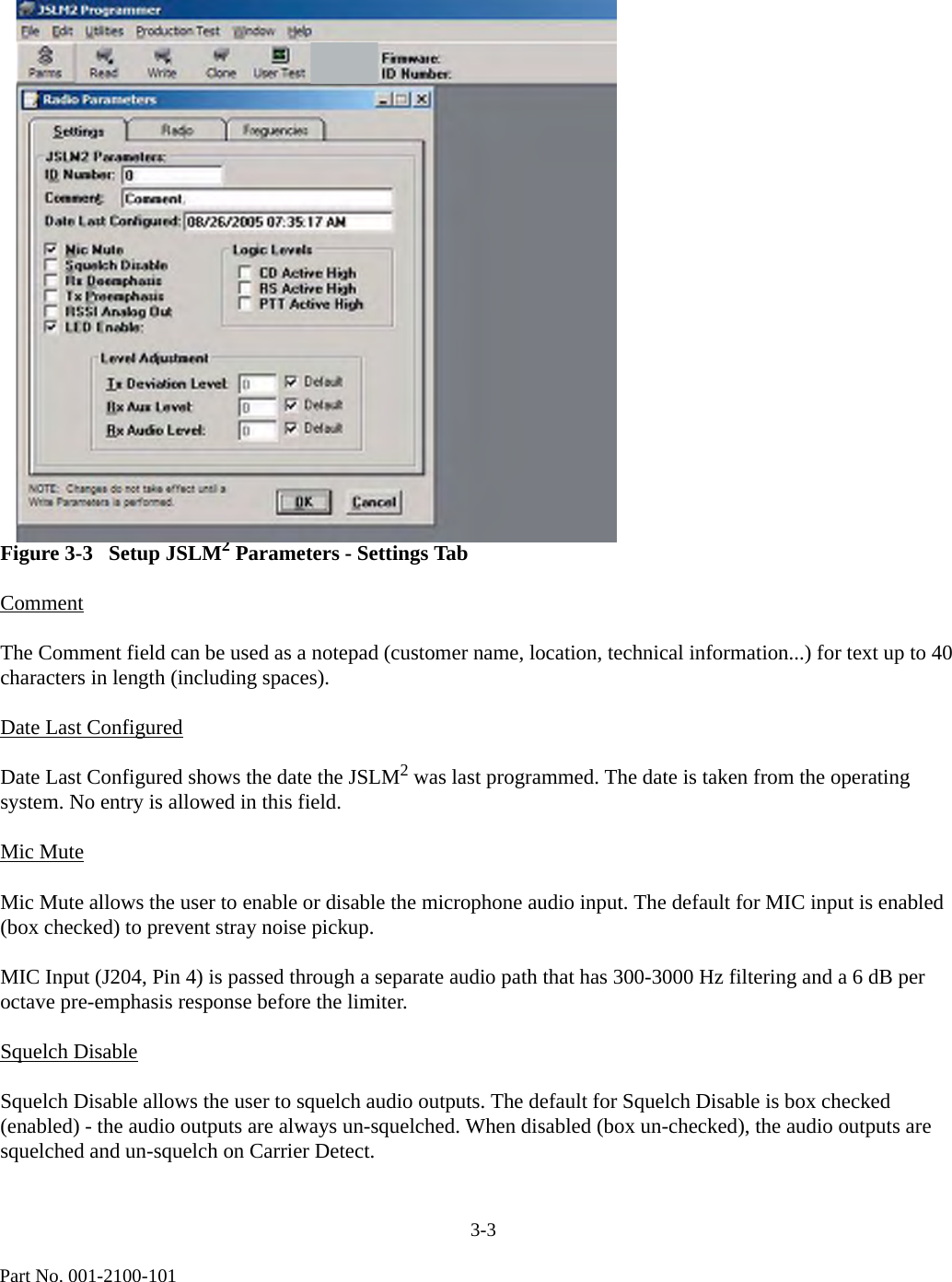
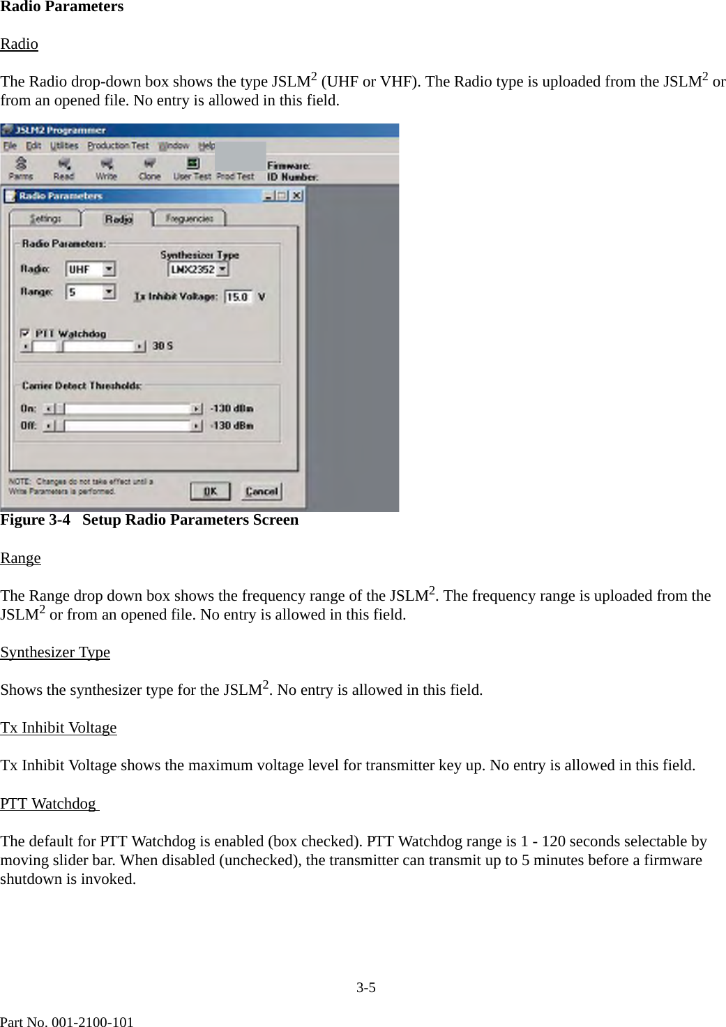
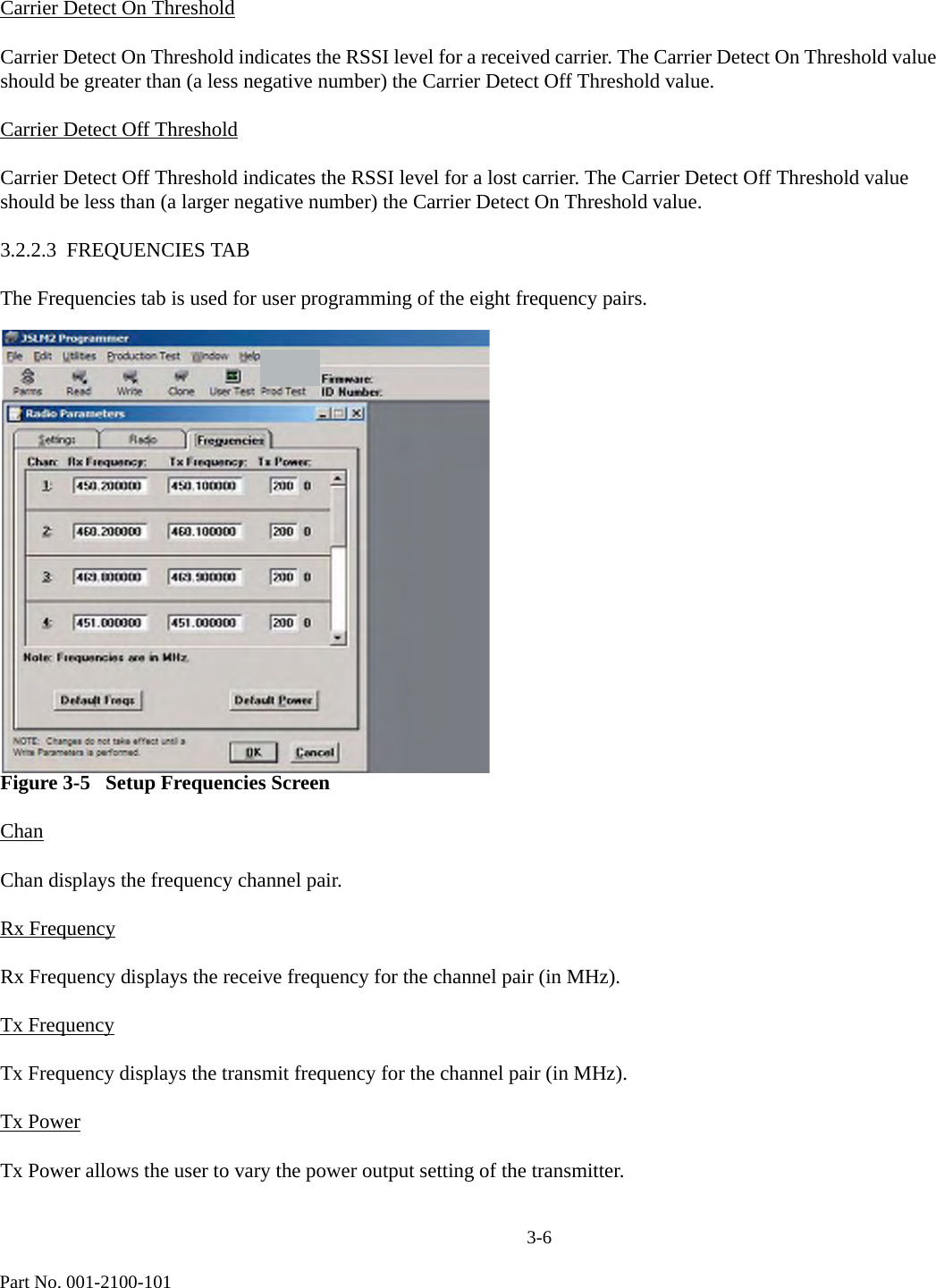
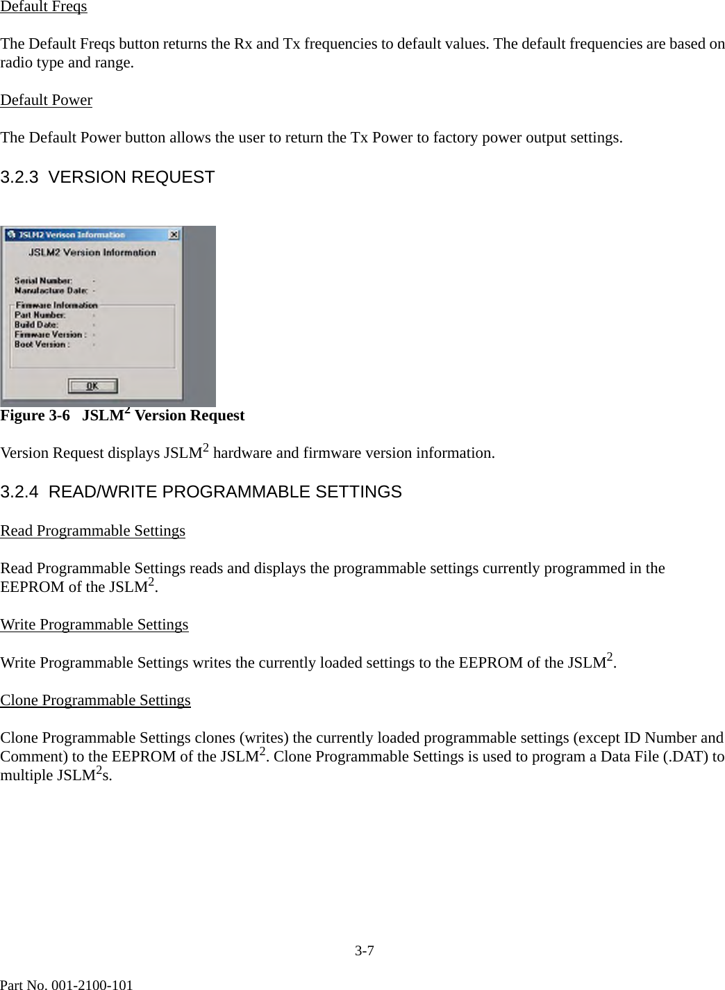
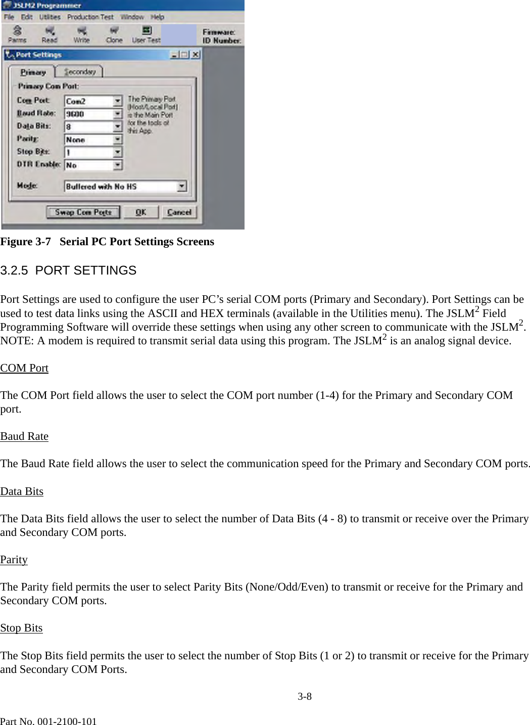
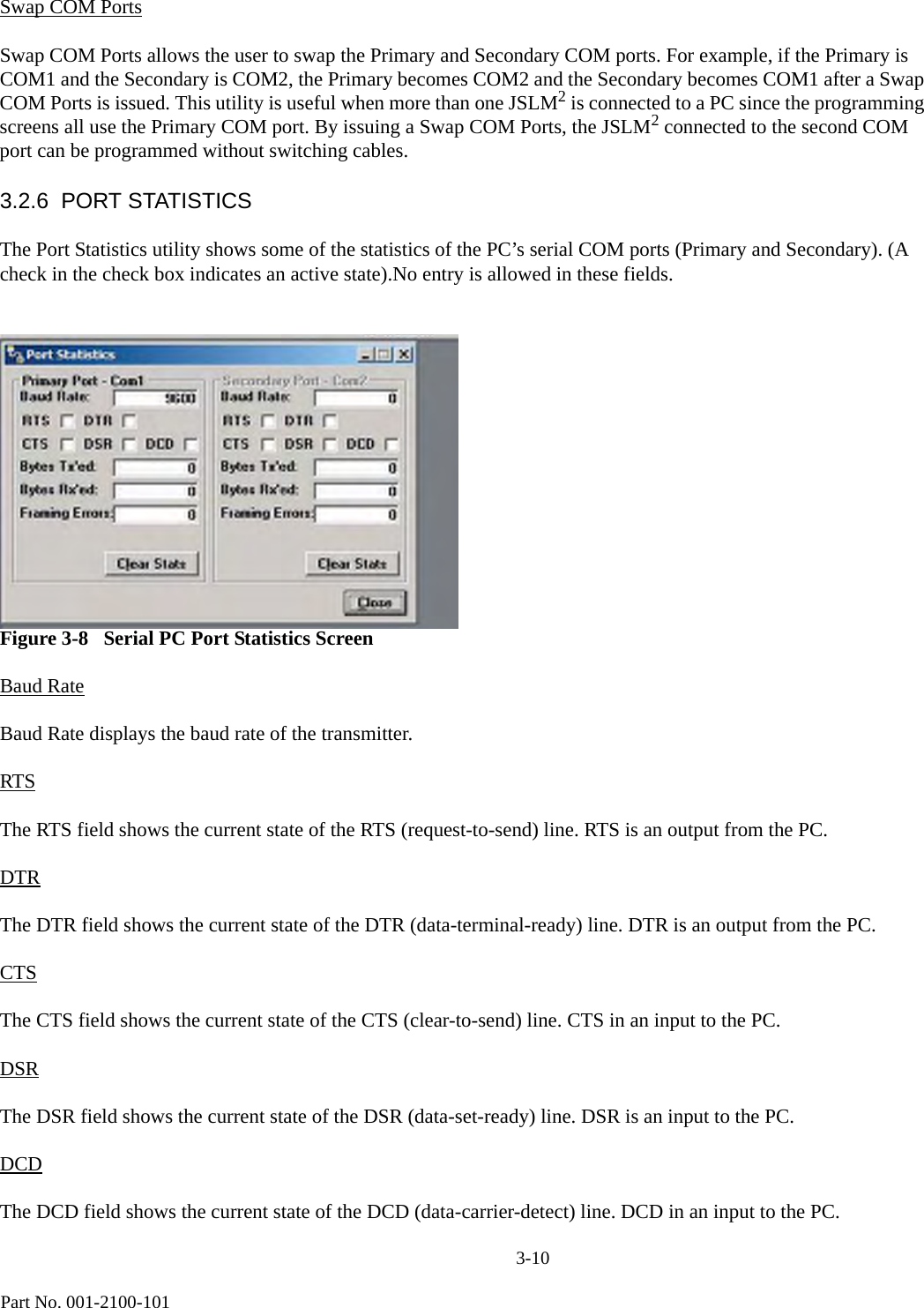
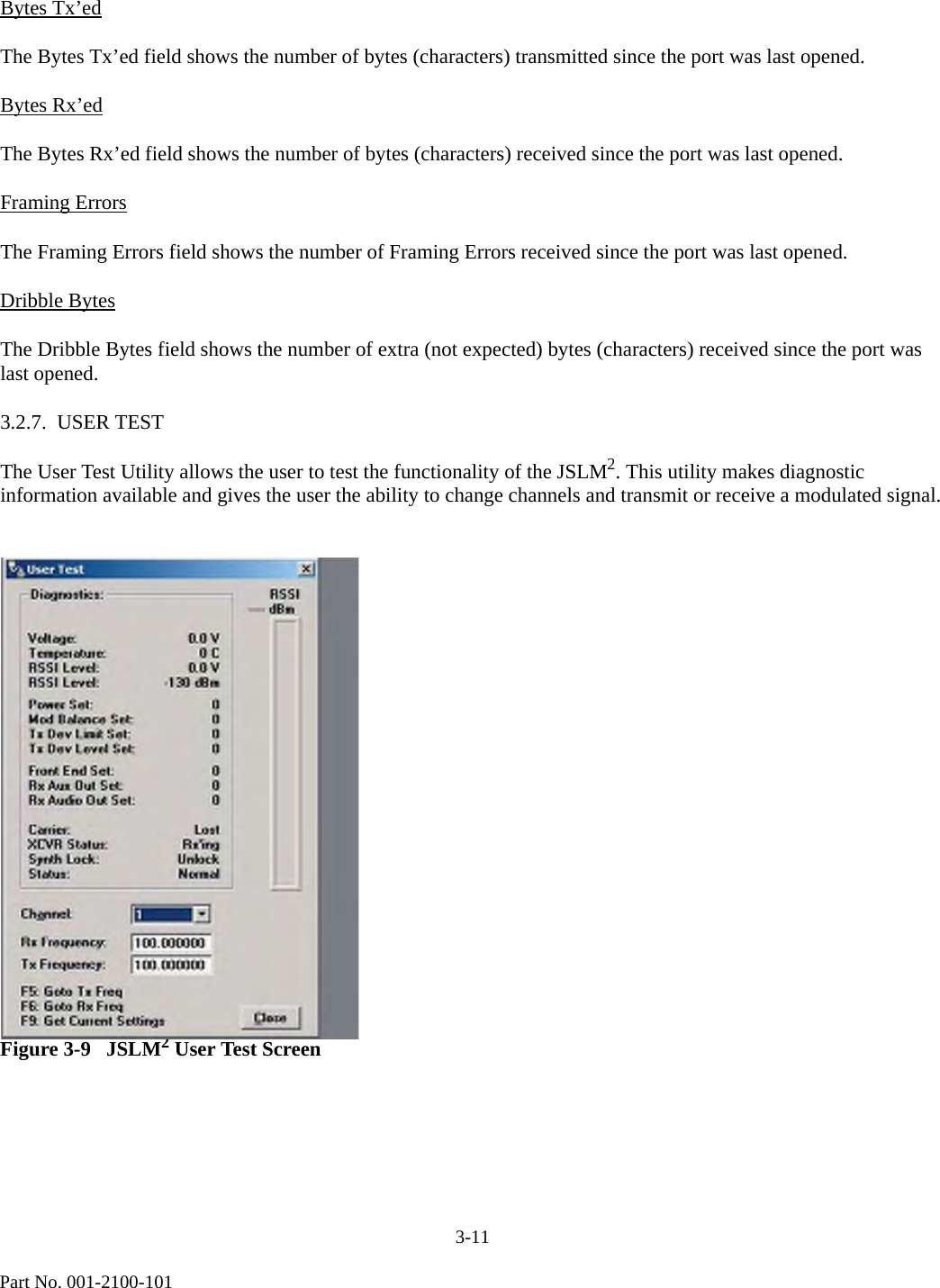
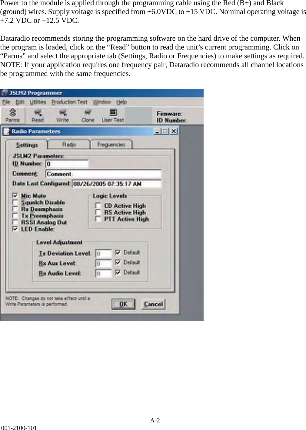
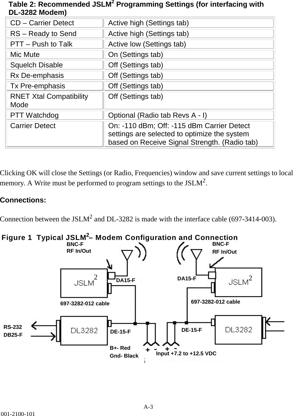
![1-4Part No. 001-2100-101GENERAL SPECIFICATIONSThese specifications are subject to change without notice.GENERAL JSLM2 INFORMATION Frequency Range 137-162 MHz, 150-174 MHz, 450-470 MHz, 406-430 MHzFrequency Control SynthesizedO pe r at i ng Vo lt a g e 6 - 1 5 V D C Channel Spacing 12.5 kHzMode of Operation Simplex or Half DuplexRF Input/Output BNC JackPower and Data Interface DA-15 (15 pin D)Receive Current Drain <100 mA (w/o Field Programming Software Cable)Transmit Current Drain 1200 mA max @ 7.2 VDC, <2000 mA max @ 12.5 VDCOperating Temperature -30° to +60° C (-22° to +140° F)Maximum Dimensions 1.0" (H)x2.5”(W) x 3.7”(L)[2.54cm (H) x 6.35 cm (W) x 9.40 cm (L)]Weight 8 oz.Regulatory FCC, Industry CanadaJSLM2 RECEIVERBandwidth UHF: 16 MHz (-210) 20 MHz (-510) VHF: 24 MHz (610), 25 MHz (710)Frequency Stability ±1.5 PPMSensitivity -12 dB SINAD <-116 dBmRF Input Impedance 50 ohmsSelectivity 60 dB (12.5 kHz)Spurious and Image Rejection 70 dB Intermodulation 70 dBFM Hum and Noise 40 dB (12.5 kHz) Conducted Spurious <-57 dBmRECEIVE CARRIER DETECT Attack Time <3ms to 50% rated audio out with a -80 dBm RF input from audio squelchCold Start <40 ms from power on cold start to carrier detect with a -80 dBm RF inputRECEIVE AUDIO RESPONSE referenced to 1 kHz tone Auxiliary Out w/o de-emphasis +1/−3 dB from 300 Hz to 2.5 kHzAuxiliary Out with de-emphasis +1/-3 dB with 6 dB de-emphasisAudio Out +1/-3 dB with 6 dB de-emphasisRECEIVE AUDIO OUTPUT LEVEL @ 1 kHz tone 60% rated deviation (factory set levels) Auxiliary Out w/o de-emphasis 212 mVrms +18 mV, 0.60 Vp-p ± 0 . 0 5 V p - p , i n t o 6 0 0 o h m , A C C o u p l e d Auxiliary Out with de-emphasis 160 mVrms +18 mV, 0.45 Vp-p ± 0 . 0 5 V p - p , i n t o 6 0 0 o h m , A C C o u p l e d Audio Out 212 mVrms +18 mV, 0.60 Vp-p ± 0.05 Vp-p, into 2k ohm, AC Coupled RECEIVE AUDIO OUTPUT MIN./MAX. ADJUSTMENT RANGE 1 kHz tone 60% rated deviationAuxiliary Out w/o de-emphasis 50-400 mVrms into 600 ohm loadAuxiliary Out with de-emphasis 50-300 mVrms into 600 ohm loadAudio Out 50-212 mVrms into 2k ohm loadRECEIVE AUDIO DISTORTION Auxiliary Out <3%(Psophometrically weighted) Audio Out <3%(Psophometrically weighted)JSLM2 TRANSMITTERBandwidth UHF: 16 MHz (-210) 20 MHz (-510) VHF: 24 MHz (610), 25 MHz (710) Frequency Stability ±1.5 PPMTCXO Coupling DCRF Power Output Programmable 0.10 to 2.00 @ 7.2 Vdc Programmable 0.50 to 5.00 Watts @ 12.5 Vdc](https://usermanual.wiki/CalAmp-Wireless-Networks/2422110610/User-Guide-588531-Page-10.png)