CalAmp Wireless Networks 2422140510 Synthesized Telemetry Module User Manual Cover
CalAmp Wireless Networks Corporation Synthesized Telemetry Module Cover
manual

Part Number: 001-2140-101
Revision 000
September 2005
Copyright 2005 Dataradio COR Ltd.
Synthesized UHF Telemetry Transceiver
Synthesized Telemetry Module
Preliminary
Part Number: 001-2100-101
Revision 000
September 2005
Copyright 2005 Dataradio COR Ltd.

About Dataradio
Dataradio is the leading designer and manufacturer of trusted wireless products and systems for critical
infrastructure applications. Our products have been found at the heart of mobile and SCADA data
networks around the world for over 20 years. Dataradio products include mobile data products and
systems, telemetry devices, integrated wireless modems for fixed point-to-point and point to multi-point
applications and OEM solutions. Our product line is one of the broadest and most trusted in the industry.
Product Warranty
The manufacturer's warranty statement for this product is available in our manuals or by contacting
Dataradio COR Ltd. 299 Johnson Avenue, Suite 110, Waseca, MN 56093-0833. Phone (507) 833-8819.
www.dataradio.com
Dataradio provides product brochures, case studies software downloads and product information on our
website.
Every effort is taken to provide accurate, timely product information in this installation manual. Product updates
may result in differences between the information provided herein and the product shipped. The information in
this document is subject to change without notice.
Dataradio is a registered trademark of Dataradio, Inc.

TABLE OF CONTENTS
1
Part No. 001-2100-101
1 GENERAL INFORMATION
1.1 SCOPE OF MANUAL. . . . . . . . . . . . . . . . . . . . . . . . . . . . . . . . . . . . . . . . . . . . . . . . . . . . . . . . . . . . . . . 1-1
1.2 EQUIPMENT DESCRIPTION. . . . . . . . . . . . . . . . . . . . . . . . . . . . . . . . . . . . . . . . . . . . . . . . . . . . . . . . . 1-1
GENERAL. . . . . . . . . . . . . . . . . . . . . . . . . . . . . . . . . . . . . . . . . . . . . . . . . . . . . . . . . . . . . . . . . . . . . . . . 1-1
JSLM
2
RADIO/LOADER . . . . . . . . . . . . . . . . . . . . . . . . . . . . . . . . . . . . . . . . . . . . . . . . . . . . . . . . . . . . . 1-1
1.3 MODULE IDENTIFICATION. . . . . . . . . . . . . . . . . . . . . . . . . . . . . . . . . . . . . . . . . . . . . . . . . . . . . . . . . . 1-1
1.4 PART NUMBER BREAKDOWN . . . . . . . . . . . . . . . . . . . . . . . . . . . . . . . . . . . . . . . . . . . . . . . . . . . . . . 1-2
1.5 ACCESSORIES . . . . . . . . . . . . . . . . . . . . . . . . . . . . . . . . . . . . . . . . . . . . . . . . . . . . . . . . . . . . . . . . . . . 1-2
1.6 TECHNICAL SUPPORT. . . . . . . . . . . . . . . . . . . . . . . . . . . . . . . . . . . . . . . . . . . . . . . . . . . . . . . . . . . . . 1-3
1.7 PRODUCT WARRANTY . . . . . . . . . . . . . . . . . . . . . . . . . . . . . . . . . . . . . . . . . . . . . . . . . . . . . . . . . . . . 1-3
1.8 REPLACEMENT PARTS . . . . . . . . . . . . . . . . . . . . . . . . . . . . . . . . . . . . . . . . . . . . . . . . . . . . . . . . . . . . 1-3
1.9 FACTORY REPAIR . . . . . . . . . . . . . . . . . . . . . . . . . . . . . . . . . . . . . . . . . . . . . . . . . . . . . . . . . . . . . . . . 1-3
GENERAL JSLM
2
INFORMATION (SPECIFICATIONS) . . . . . . . . . . . . . . . . . . . . . . . . . . . . . . . . . . . . 1-4
2INSTALLATION
2.1 PRE-INSTALLATION CHECKS. . . . . . . . . . . . . . . . . . . . . . . . . . . . . . . . . . . . . . . . . . . . . . . . . . . . . . . 2-1
2.2 INTERFACING WITH THE JSLM
2
. . . . . . . . . . . . . . . . . . . . . . . . . . . . . . . . . . . . . . . . . . . . . . . . . . . . . 2-1
PROGRAMMING AND POWER CABLE . . . . . . . . . . . . . . . . . . . . . . . . . . . . . . . . . . . . . . . . . . . . . . . . 2-1
ANTENNA AND VSWR . . . . . . . . . . . . . . . . . . . . . . . . . . . . . . . . . . . . . . . . . . . . . . . . . . . . . . . . . . . . . 2-1
CONNECTOR J204 USER INTERFACE . . . . . . . . . . . . . . . . . . . . . . . . . . . . . . . . . . . . . . . . . . . . . . . . 2-1
GENERAL PINOUT DESCRIPTION. . . . . . . . . . . . . . . . . . . . . . . . . . . . . . . . . . . . . . . . . . . . . . . . . . . . 2-2
3 PROGRAMMING
3.1 INTRODUCTION . . . . . . . . . . . . . . . . . . . . . . . . . . . . . . . . . . . . . . . . . . . . . . . . . . . . . . . . . . . . . . . . . . 3-1
GENERAL. . . . . . . . . . . . . . . . . . . . . . . . . . . . . . . . . . . . . . . . . . . . . . . . . . . . . . . . . . . . . . . . . . . . . . . . 3-1
3.2 JSLM
2
FIELD PROGRAMMING SOFTWARE. . . . . . . . . . . . . . . . . . . . . . . . . . . . . . . . . . . . . . . . . . . . 3-1
INTRODUCTION . . . . . . . . . . . . . . . . . . . . . . . . . . . . . . . . . . . . . . . . . . . . . . . . . . . . . . . . . . . . . . . . . . 3-1
RADIO PARAMETERS. . . . . . . . . . . . . . . . . . . . . . . . . . . . . . . . . . . . . . . . . . . . . . . . . . . . . . . . . . . . . . 3-2
SETTINGS TAB . . . . . . . . . . . . . . . . . . . . . . . . . . . . . . . . . . . . . . . . . . . . . . . . . . . . . . . . . . . . . . . . . . . 3-2
RADIO TAB. . . . . . . . . . . . . . . . . . . . . . . . . . . . . . . . . . . . . . . . . . . . . . . . . . . . . . . . . . . . . . . . . . . . . . . 3-4
FREQUENCIES TAB . . . . . . . . . . . . . . . . . . . . . . . . . . . . . . . . . . . . . . . . . . . . . . . . . . . . . . . . . . . . . . . 3-6
VERSION REQUEST . . . . . . . . . . . . . . . . . . . . . . . . . . . . . . . . . . . . . . . . . . . . . . . . . . . . . . . . . . . . . . . 3-7
READ/WRITE PROGRAMMABLE SETTINGS. . . . . . . . . . . . . . . . . . . . . . . . . . . . . . . . . . . . . . . . . . . . 3-7
PORT SETTINGS . . . . . . . . . . . . . . . . . . . . . . . . . . . . . . . . . . . . . . . . . . . . . . . . . . . . . . . . . . . . . . . . . . 3-8
PORT STATISTICS . . . . . . . . . . . . . . . . . . . . . . . . . . . . . . . . . . . . . . . . . . . . . . . . . . . . . . . . . . . . . . . 3-10
USER TEST . . . . . . . . . . . . . . . . . . . . . . . . . . . . . . . . . . . . . . . . . . . . . . . . . . . . . . . . . . . . . . . . . . . . . 3-11
ASCII/HEX TERMINAL. . . . . . . . . . . . . . . . . . . . . . . . . . . . . . . . . . . . . . . . . . . . . . . . . . . . . . . . . . . . . 3-13
3.3 JSLM
2
FIELD PROGRAMMING SOFTWARE HELP FILES. . . . . . . . . . . . . . . . . . . . . . . . . . . . . . . . 3-13
4 ALIGNMENT AND TROUBLESHOOTING
4.1 GENERAL . . . . . . . . . . . . . . . . . . . . . . . . . . . . . . . . . . . . . . . . . . . . . . . . . . . . . . . . . . . . . . . . . . . . . . . 4-1
PERIODIC CHECKS. . . . . . . . . . . . . . . . . . . . . . . . . . . . . . . . . . . . . . . . . . . . . . . . . . . . . . . . . . . . . . . . 4-1
SERVICING . . . . . . . . . . . . . . . . . . . . . . . . . . . . . . . . . . . . . . . . . . . . . . . . . . . . . . . . . . . . . . . . . . . . . . 4-1
4.2 PERFORMANCE CHECKS . . . . . . . . . . . . . . . . . . . . . . . . . . . . . . . . . . . . . . . . . . . . . . . . . . . . . . . . . . 4-1
CHANNEL FREQUENCY . . . . . . . . . . . . . . . . . . . . . . . . . . . . . . . . . . . . . . . . . . . . . . . . . . . . . . . . . . . . 4-1

TABLE OF CONTENTS
2
Part No. 001-2100-101
RF OUTPUT POWER. . . . . . . . . . . . . . . . . . . . . . . . . . . . . . . . . . . . . . . . . . . . . . . . . . . . . . . . . . . . . . . 4-1
TRANSMIT DEVIATION . . . . . . . . . . . . . . . . . . . . . . . . . . . . . . . . . . . . . . . . . . . . . . . . . . . . . . . . . . . . . 4-2
TRANSMIT DEVIATION LIMITING. . . . . . . . . . . . . . . . . . . . . . . . . . . . . . . . . . . . . . . . . . . . . . . . . . . . . 4-2
RECEIVE AUX OUT AND AUDIO OUT LEVELS . . . . . . . . . . . . . . . . . . . . . . . . . . . . . . . . . . . . . . . . . . 4-2
4.3 TROUBLESHOOTING . . . . . . . . . . . . . . . . . . . . . . . . . . . . . . . . . . . . . . . . . . . . . . . . . . . . . . . . . . . . . . 4-2
APPENDIX A
TECHNICAL SUPPORT APPLICATION NOTE . . . . . . . . . . . . . . . . . . . . . . . . . . . . . . . . . . . . . . . . .A-1/3
RF EXPOSURE COMPLIANCE - VHF JSLM
2
TELEMETRY MODULE. . . . . . . . . . . . . . . . . . . . . . . . A-4
RF EXPOSURE COMPLIANCE - UHF JSLM
2
TELEMETRY MODULE. . . . . . . . . . . . . . . . . . . . . . . . A-5
PRODUCT WARRANTY . . . . . . . . . . . . . . . . . . . . . . . . . . . . . . . . . . . . . . . . . . . . . . . . . . . . . . . . . . . . A-6
LIST OF FIGURES
MODULE IDENTIFICATION . . . . . . . . . . . . . . . . . . . . . . . . . . . . . . . . . . . . . . . . . . . . . . . . . . . . . . . . . . 1-1
1-1 JSLM
2
TELEMETRY MODULE . . . . . . . . . . . . . . . . . . . . . . . . . . . . . . . . . . . . . . . . . . . . . . . . . . . . . . . 1-2
1-2 VHF TYPICAL OUTPUT POWER VS. SUPPLY VOLTAGE . . . . . . . . . . . . . . . . . . . . . . . . . . . . . . . . . 1-6
1-3 UHF TYPICAL OUTPUT POWER VS. SUPPLY VOLTAGE . . . . . . . . . . . . . . . . . . . . . . . . . . . . . . . . . 1-7
2-1 JSLM
2
MODULE. . . . . . . . . . . . . . . . . . . . . . . . . . . . . . . . . . . . . . . . . . . . . . . . . . . . . . . . . . . . . . . . . . . 2-1
2-2 JSLM
2
ACCESSORY INTERCONNECT POWER CABLE. . . . . . . . . . . . . . . . . . . . . . . . . . . . . . . . . . . 2-3
3-1 JSLM
2
FIELD PROGRAMMING SOFTWARE SETUP. . . . . . . . . . . . . . . . . . . . . . . . . . . . . . . . . . . . . . 3-1
3-2 JSLM
2
FIELD PROGRAMMING SOFTWARE START-UP SCREEN. . . . . . . . . . . . . . . . . . . . . . . . . . . 3-2
3-3 SETUP JSLM
2
PARAMETERS - SETTINGS TAB . . . . . . . . . . . . . . . . . . . . . . . . . . . . . . . . . . . . . . . . . 3-3
3-4 SETUP RADIO PARAMETERS SCREEN . . . . . . . . . . . . . . . . . . . . . . . . . . . . . . . . . . . . . . . . . . . . . . . 3-5
3-5 SETUP FREQUENCIES SCREEN . . . . . . . . . . . . . . . . . . . . . . . . . . . . . . . . . . . . . . . . . . . . . . . . . . . . . 3-6
3-6 JSLM
2
VERSION REQUEST . . . . . . . . . . . . . . . . . . . . . . . . . . . . . . . . . . . . . . . . . . . . . . . . . . . . . . . . . 3-7
3-7 SERIAL PC PORT SETTINGS SCREENS. . . . . . . . . . . . . . . . . . . . . . . . . . . . . . . . . . . . . . . . . . . . . . . 3-8
3-8 SERIAL PC PORT STATISTICS SCREEN . . . . . . . . . . . . . . . . . . . . . . . . . . . . . . . . . . . . . . . . . . . . . 3-10
3-9 JSLM
2
USER TEST SCREEN . . . . . . . . . . . . . . . . . . . . . . . . . . . . . . . . . . . . . . . . . . . . . . . . . . . . . . . 3-11
3-10 ASCII TERMINAL SCREEN . . . . . . . . . . . . . . . . . . . . . . . . . . . . . . . . . . . . . . . . . . . . . . . . . . . . . . . . . 3-13
4-1 JSLM
2
RF BOARD ADJUSTMENT POINTS . . . . . . . . . . . . . . . . . . . . . . . . . . . . . . . . . . . . . . . . . . . . . 4-4
4-2 JSLM
2
LOADER ADJUSTMENT POINTS . . . . . . . . . . . . . . . . . . . . . . . . . . . . . . . . . . . . . . . . . . . . . . . 4-4
LIST OF TABLES
1-1 ACCESSORIES . . . . . . . . . . . . . . . . . . . . . . . . . . . . . . . . . . . . . . . . . . . . . . . . . . . . . . . . . . . . . . . . . . . 1-2
1-2 VHF RSSI VOLTAGES VS RF INPUT LEVEL @ J204, PIN 11. . . . . . . . . . . . . . . . . . . . . . . . . . . . . . . 1-5
1-2 UHF RSSI VOLTAGES VS RF INPUT LEVEL @ J204, PIN 11. . . . . . . . . . . . . . . . . . . . . . . . . . . . . . . 1-5
2-1 CHANNEL SELECT . . . . . . . . . . . . . . . . . . . . . . . . . . . . . . . . . . . . . . . . . . . . . . . . . . . . . . . . . . . . . . . . 2-2
3-1 LED FUNCTIONS . . . . . . . . . . . . . . . . . . . . . . . . . . . . . . . . . . . . . . . . . . . . . . . . . . . . . . . . . . . . . . . . . . 3-4
3-2 COMMUNICATION MODES. . . . . . . . . . . . . . . . . . . . . . . . . . . . . . . . . . . . . . . . . . . . . . . . . . . . . . . . . . 3-9

TABLE OF CONTENTS
3
Part No. 001-2100-101
Revision History
Revision 000
Manual release

SECTION 1
GENERAL INFORMATION
1-1
Part No. 001-2100-101
1.1 SCOPE OF MANUAL
This installation manual contains operating instructions for the Dataradio JSLM2 Synthesized Telemetry module.
This document is intended for system designers, system consultants and JSLM2 end-users.
1.2 EQUIPMENT DESCRIPTION
1.2.1 GENERAL
The Dataradio JSLM2 module (transmitter and receiver) operates in the VHF or UHF frequency range. The
transmitter power output is electrically programmable from 0.10 to 5.00 Watts. Operation is simplex or half
duplex. The JSLM2 module has a frequency stability of ± 1.5 PPM. The module may be used for voice and/or low
speed data communications with an external modem.
1.2.2 JSLM2 RADIO/LOADER
The JSLM2 includes the 8-channel Loader Board which performs synthesizer loading. The Loader Board has
circuitry which provides transmit/receive audio conditioning and gating, carrier detect, and RSSI buffering. The
gating circuits allow the user to select audio response type: flat, pre-emphasis or de-emphasis. The receiver audio
outputs and transmitter audio inputs are electronically programmable.
This board is programmed using a personal computer with a Windows® 95 or newer operating system and the
JSLM2 Field Programming Software. Programming information is stored by an EEPROM on the RF Board.
1.3 MODULE IDENTIFICATION
The module identification number is a random, unique serial number (SN) printed on the shipping box and the
model label on the side of the module.
JSLM2
Model: 242-2140-XXX
FCC ID: NP4-2422140510
Canada
SN XXXX
Made in USA
:
773B-2140510
JSLM2
Model: 242-2110-XXX
FCC ID: NP4-2422110610
Canada: 773B-2110610
SN XXXX
Made in USA
1-2
Part No. 001-2100-101
1.4 PART NUMBER BREAKDOWN
The following is a breakdown of the part number used to identify this module:
1.5 ACCESSORIES
Accessories available for the JSLM2 module are listed in Table 1-1.
*See Appendix A for the Technical Support Application note to interface the JSLM2 with the external
1200 Baud Modem.
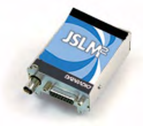
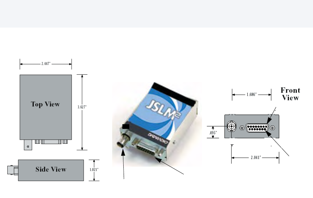
Figure 1-1 JSLM2 Telemetry Module
Table 1-1 ACCESSORIES
Accessory Part No.
JSLM2 Programming Kit 250-2100-001
External 1200 Baud Modem* 250-3282-002
JSLM2 Interconnect Power Cable 023-3414-003
JSLM2 to 3282 Interconnect Cable 697-3282-012
242-21X0 - Y 1 0
7 = 132-160 MHz
6 = 150-174 MHz
5 = 450-470 MHz
2 = 406-430 MHz
1 = VHF
4 = UHF

1-3
Part No. 001-2100-101
1.6 TECHNICAL SUPPORT
The Technical Service Department of Dataradio provides customer assistance on technical problems and serves as
an interface with factory repair facilities. They can be reached by mail, phone, and E-mail at:
Dataradio COR Ltd. Technical Service Department
299 Johnson Avenue, Suite 110
Waseca, MN 56093-0833
Technical Service hours are: Monday to Friday 7:30 AM to 4:30 PM, Central Time
Phone: 800-992-7774 or 507-833-8819
Fax: 507-833-6758
E-mail address: support@dataradio.com
1.7 PRODUCT WARRANTY
The warranty statement for the JSLM2 is available in the Appendix area of this manual.
1.8 REPLACEMENT PARTS
This product is not field serviceable, except by the replacement of complete units. Specialized equipment and
training is required to repair logic boards and radio modules.
1.9 FACTORY REPAIR
Dataradio products are designed for long life and failure-free operation. If a problem arises, factory service is
available. Contact the Technical Service Department before returning equipment. A service representative may
suggest a solution eliminating the need to return equipment.
A Return Material Authorization (RMA) is required when returning equipment to Dataradio for repair. Contact the
Technical Service Department at 800-992-7774, extension 6707 to request an RMA number. Be prepared to give
the equipment model and serial number, your account number (if known), and billing and shipping addresses.
Information regarding equipment return is also available on our website at www.dataradio.com
Include the RMA number, a complete description of the problem, and the name and phone number of a contact
person with the returned units. This information is important. The technician may have questions that need to be
answered to identify the problem and repair the equipment. The RMA number helps locate your equipment in the
repair lab if there is a need to contact Dataradio concerning the equipment. Units sent in for repair will be returned
to the customer re-tuned to the current Dataradio Test and Tune Procedure and will conform to all specifications
noted in this section
Customers are responsible for shipping charges (to Dataradio) for returned units in warranty. Units in warranty are
repaired free of charge unless there is evidence of abuse or damage beyond the terms of the warranty. Dataradio
covers return shipping costs for equipment repaired while under warranty.
Units out of warranty are subject to repair service charges. Customers are responsible for shipping charges (to and
from Dataradio) on units out of warranty. Return shipping instructions are the responsibility of the customer.

1-4
Part No. 001-2100-101
GENERAL SPECIFICATIONS
These specifications are subject to change without notice.
GENERAL JSLM2 INFORMATION
Frequency Range 137-162 MHz, 150-174 MHz, 450-470 MHz, 406-430 MHz
Frequency Control Synthesized
O pe r at i ng Vo lt a g e 6 - 1 5 V D C
Channel Spacing 12.5 kHz
Mode of Operation Simplex or Half Duplex
RF Input/Output BNC Jack
Power and Data Interface DA-15 (15 pin D)
Receive Current Drain <100 mA (w/o Field Programming Software Cable)
Transmit Current Drain 1200 mA max @ 7.2 VDC, <2000 mA max @ 12.5 VDC
Operating Temperature -30° to +60° C (-22° to +140° F)
Maximum Dimensions 1.0" (H)x2.5”(W) x 3.7”(L)[2.54cm (H) x 6.35 cm (W) x 9.40 cm (L)]
Weight 8 oz.
Regulatory FCC, Industry Canada
JSLM2 RECEIVER
Bandwidth UHF: 16 MHz (-210) 20 MHz (-510) VHF: 24 MHz (610), 25 MHz (710)
Frequency Stability ±1.5 PPM
Sensitivity -12 dB SINAD <-116 dBm
RF Input Impedance 50 ohms
Selectivity 60 dB (12.5 kHz)
Spurious and Image Rejection 70 dB
Intermodulation 70 dB
FM Hum and Noise 40 dB (12.5 kHz)
Conducted Spurious <-57 dBm
RECEIVE CARRIER DETECT
Attack Time <3ms to 50% rated audio out with a -80 dBm RF input from audio squelch
Cold Start <40 ms from power on cold start to carrier detect with a -80 dBm RF input
RECEIVE AUDIO RESPONSE referenced to 1 kHz tone
Auxiliary Out w/o de-emphasis +1/−3 dB from 300 Hz to 2.5 kHz
Auxiliary Out with de-emphasis +1/-3 dB with 6 dB de-emphasis
Audio Out +1/-3 dB with 6 dB de-emphasis
RECEIVE AUDIO OUTPUT LEVEL @ 1 kHz tone 60% rated deviation (factory set levels)
Auxiliary Out w/o de-emphasis 212 mVrms +18 mV, 0.60 Vp-p ± 0 . 0 5 V p - p , i n t o 6 0 0 o h m , A C C o u p l e d
Auxiliary Out with de-emphasis 160 mVrms +18 mV, 0.45 Vp-p ± 0 . 0 5 V p - p , i n t o 6 0 0 o h m , A C C o u p l e d
Audio Out 212 mVrms +18 mV, 0.60 Vp-p ± 0.05 Vp-p, into 2k ohm, AC Coupled
RECEIVE AUDIO OUTPUT MIN./MAX. ADJUSTMENT RANGE 1 kHz tone 60% rated deviation
Auxiliary Out w/o de-emphasis 50-400 mVrms into 600 ohm load
Auxiliary Out with de-emphasis 50-300 mVrms into 600 ohm load
Audio Out 50-212 mVrms into 2k ohm load
RECEIVE AUDIO DISTORTION
Auxiliary Out <3%(Psophometrically weighted)
Audio Out <3%(Psophometrically weighted)
JSLM2 TRANSMITTER
Bandwidth UHF: 16 MHz (-210) 20 MHz (-510) VHF: 24 MHz (610), 25 MHz (710)
Frequency Stability ±1.5 PPM
TCXO Coupling DC
RF Power Output Programmable 0.10 to 2.00 @ 7.2 Vdc
Programmable 0.50 to 5.00 Watts @ 12.5 Vdc

1-5
Part No. 001-2100-101
Output Power vs Supply Voltage See Figures 1-2, 1-3
RF Output Impedance 50 ohms
Modulation Distortion < 3% (Psophometrically weighted)
Spurious and Harmonic FM <-20 dBm
FM Hum and Noise -40 dB, -35 dB (242-2110-710)
TRANSMIT AUDIO RESPONSE referenced to 1 kHz tone:
Auxiliary In w/o pre-emphasis +1/−3 dB from 300 Hz to 2.5 kHz
Auxiliary In with pre-emphasis +1/-3 dB with 6 dB pre-emphasis
Audio In +1/-3 dB with 6 dB pre-emphasis
M OD U L ATI O N C A PA B IL I TY @ 1 kH z t o ne : ( F a ct o ry Se t )
Auxiliary In w/o pre-emphasis 40 mVrms ± 20% for 60% of rated deviation
Auxiliary In with pre-emphasis 200 mVrms ± 20% for 60% of rated deviation
Audio In 30 mVrms± 20% for 60% of rated deviation
TRANSMIT AUDIO DISTORTION
A u x i l i a r y I n < 3 % ( P s o p h o m e t r i c a l l y w e ig h t e d )
Audio In <3%(Psophometrically weighted)
TRANSMIT ATTACK TIME <15 ms from PTT to 100% rated power out
MODULATION CAPABILITY MIN/MAX ADJUSTMENT
Auxiliary In w/o pre-emphasis 10-80 mVrms (electronically programmable)
Auxiliary In with pre-emphasis 50-300 mVrms
Audio In No adjustment available
Measurements per TIA/EIA 603 or Dataradio COR Ltd. Specification 003-0000-000.
Table 1-2 VHF JSLM2 RSSI Voltages vs RF Input Level @ J204, Pin 11
Table 1-3 UHF JSLM2 RSSI Voltages vs RF Input Level @ J204, Pin 11
RF Input RSSI Typical RSSI Low RSSI High
Level Voltage Voltage Voltage
dBm 610 & 710 610 & 710 610 & 710
-120 0.69 0.40 0.98
-110 0.85 0.50 1.19
-100 1.02 0.66 1.38
-90 1.21 0.79 1.63
-80 1.38 0.99 1.77
-70 1.56 1.13 1.99
-60 1.75 1.32 2.18
-50 1.95 1.47 2.42
RF Input RSSI Typical RSSI Low RSSI High
Level Voltage Voltage Voltage
dBm 210 & 510 210 & 510 210 & 510
-120 0.85 0.42 1.28
-110 1.00 0.45 1.55
-100 1.19 0.57 1.81
-90 1.38 0.86 1.90
-80 1.55 0.95 2.15
-70 1.73 1.16 2.31
-60 1.93 1.25 2.60
-50 2.09 1.79 2.40
1-6
Part No. 001-2100-101
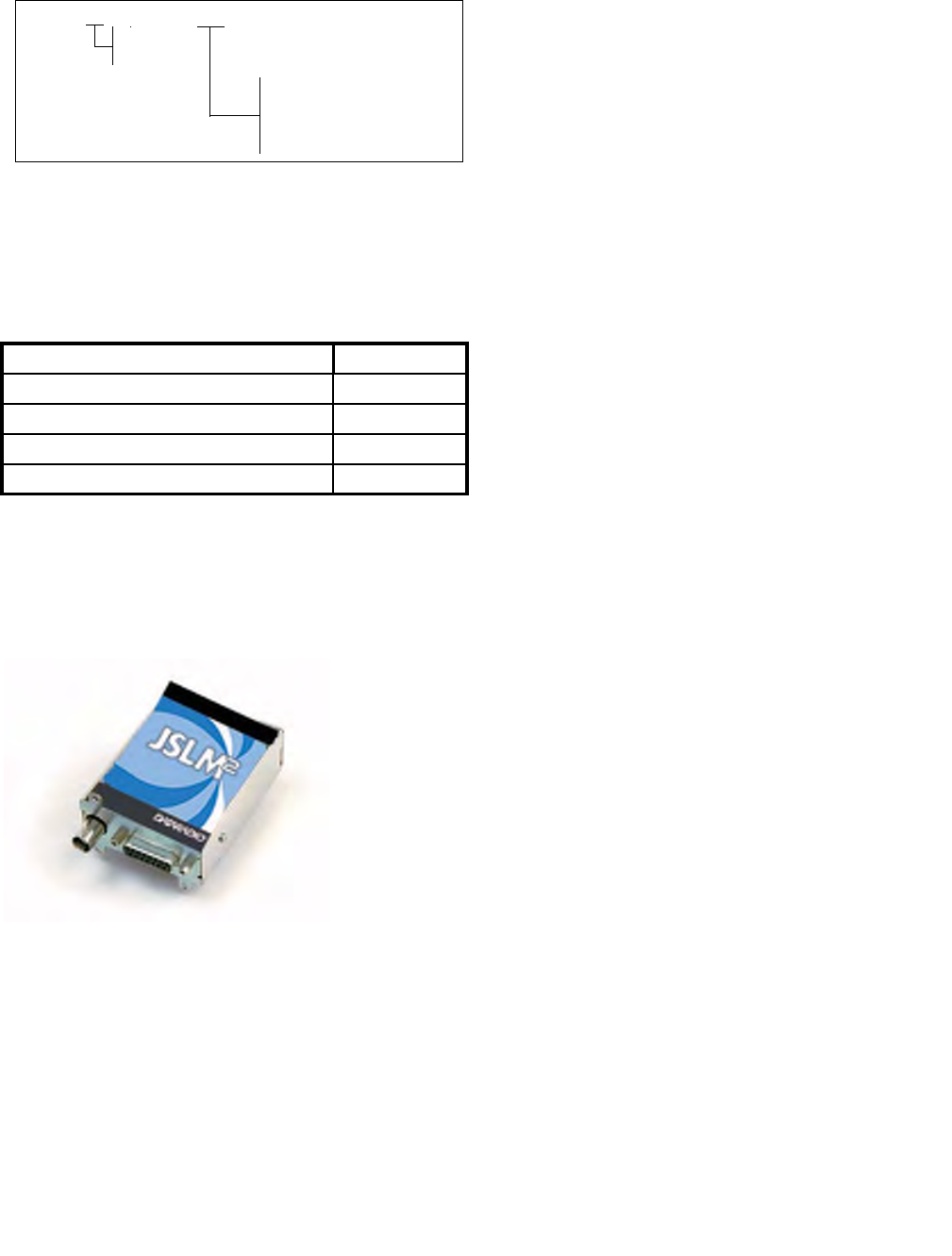
Figure 1-2 VHF Typical Output Power vs Supply Voltage
VHF
Power (W) vs. Supply (Vdc)
0
1
2
3
4
5
6
0 2 4 6 8 10 12 14 16
Supply (Vdc)
Power (W)
Power (W) vs. Supply
(Vdc)
VHF
Tx Current (A) vs. Supply (Vdc)
0.0
0.5
1.0
1.5
2.0
5 7 9 11131517
Supply (Vdc)
Tx Current (A)
Tx Current (A) vs.
Supply (Vdc)
1-7
Part No. 001-2100-101
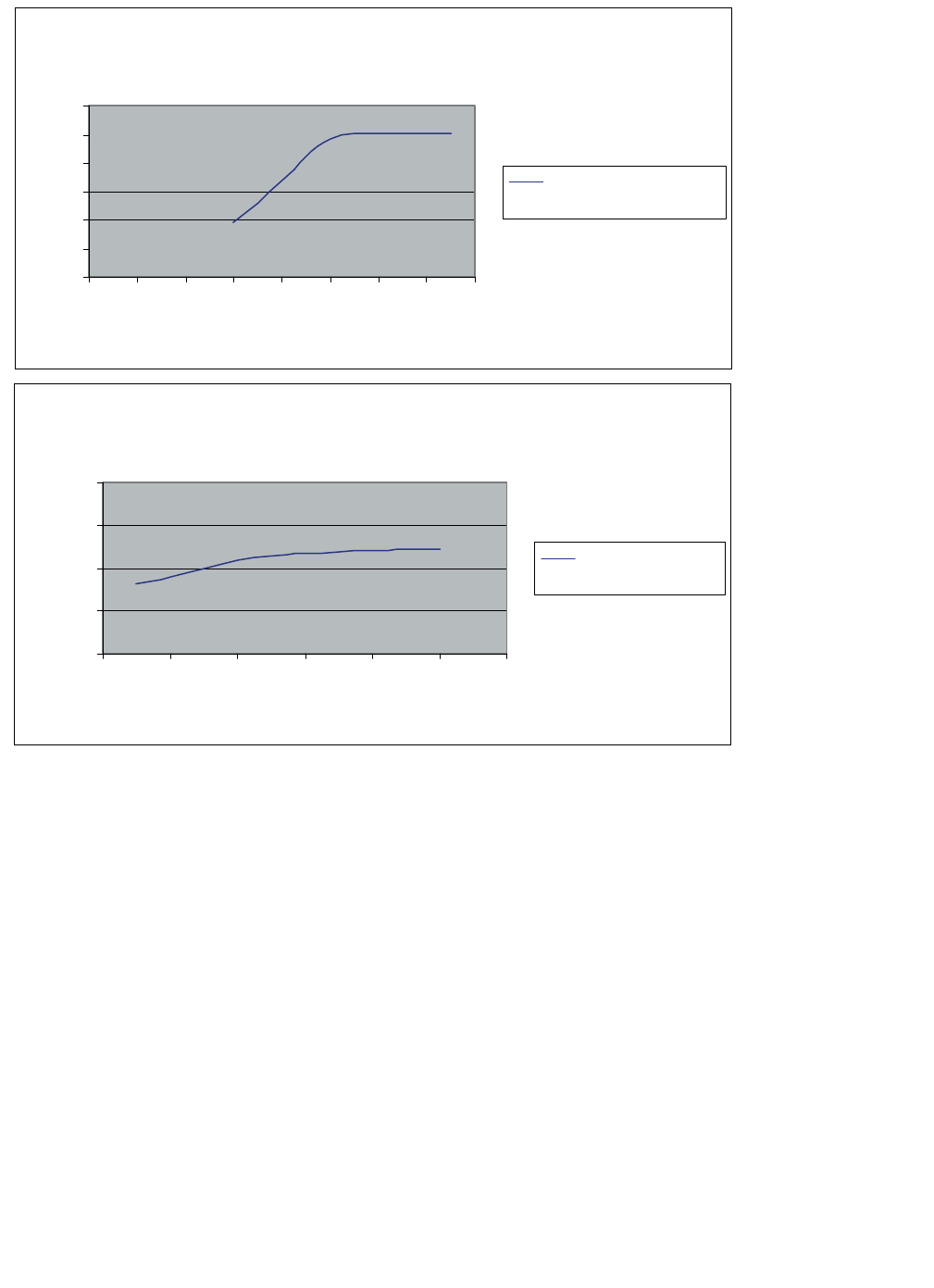
Figure 1-3 UHF Typical Output Power vs Supply Voltage
UHF
Power (W) vs Supply Voltage (V)
0
1
2
3
4
5
6
5 7 9 11131517
Supply (Vdc)
Power (W)
Power (W) vs Supply Voltage (V)
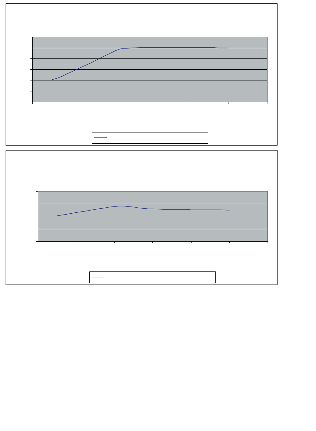
UHF
Tx Current (A) vs Supply Voltage (V)
0.0
0.5
1.0
1.5
2.0
5 7 9 11131517
Supply (Vdc)
Tx Current (A)
Tx Current (A) vs Supply Voltage (V)
SECTION 2
INSTALLATION
2-1
Part No. 001-2100-101
Figure 2-1 JSLM2 Module
2.1 PRE-INSTALLATION CHECKS
Unpack the JSLM2 Module. Inspect the unit to ensure the Module was not damaged during shipment. Save the
packing material and documentation.
2.2 INTERFACING WITH THE JSLM2
2.2.1 PROGRAMMING AND POWER CABLE
Programming and pre-installation checks may be performed with the Programming Cable supplied in the JSLM2
Field Programming Kit (Part Number 250-2100-001). For final installation, a Dataradio JSLM2 Accessory /
Interconnect Power Cable is available (see Figure 2-2). See Appendix A for the Technical Support Application
note to interface the JSLM2 with the external 1200 Baud Modem.
2.2.2 ANTENNA AND VSWR
A VSWR measurement of the antenna system should be made before the module is put into service. An accurate
VSWR meter or directional wattmeter appropriate for the frequency of operation should be used. A VSWR of less
than 2:1 is recommended. If the VSWR reading is high, check cables and connectors. Verify the antenna is
properly installed and is specified to operate on your frequency.
2.2.3 CONNECTOR J204 USER INTERFACE
Connector J204 (DA-15) provides the interface with the JSLM2 module. This is a 15-pin, female connector. See
Appendix A for the Technical Support Application note to interface the JSLM2 with the external 1200 Baud
Modem.
Antenna Connector
DA-15
(15 pin D)
(BNC)
Pin 9
Pin 1

2-2
Part No. 001-2100-101
2.2.4 GENERAL PINOUT DESCRIPTION
Table 2-1 Channel Select Table
CSO_N.... CS2_N internally pulled up to 5 VDC, ground pin for logic low.
PIN 1: Channel Select 0 (CSO_N) Switch 0
PIN 2: Channel Select 1 (CS1_N) Switch 1
PIN 3: Channel Select 2 (CS2_N) Switch 2
PIN 4: TX Microphone Input (MIC_IN) 30 mVrms nominal for 60% rated deviation.
PIN 5: Connected internally to Pin 1
PIN 6: Raw Battery Supply (7.2 or 12.5 VDC nominal) Power supply 6-15 VDC, 3 Amps maximum.
PIN 7: TX Auxiliary Input (AUX_IN) Audio input for the transmitter.
Without pre-emphasis: 40 mVrms nominal for 60% rated deviation.
With pre-emphasis: 200 mVrms nominal for 60% rated deviation.
PIN 8: RX Auxiliary Output (AUX_OUT): Audio from the receiver.
Without pre-emphasis: 212 Vrms ± 18 mV
With pre-emphasis: 160 mVrms ± 18 mV
Into a 600 ohm load
PIN 9: Program I/O From Computer
(PGM_IN_OUT) (TTL) The Interface cable (see Table 1-1) converts RS-232 to TTL logic for JSLM2
programming information.
PIN 10: Ready to Send (RS) (TTL) Radio is locked on frequency and transmitter is ready to accept audio input,
set with software active high or low.
CH CSO_N CS1_N CS2_N
1 0 0 0
2 1 0 0
3 0 1 0
4 1 1 0
5 0 0 1
6 1 0 1
7 0 1 1
8 1 1 1
2-3
Part No. 001-2100-101
PIN 11: _Squelch_Disable/RSSI Out
User programmable to:
Squelch Disable - When the Squelch Disable box is unchecked, the receive audio is squelched. Grounding
Pin 11 will un-squelch the receive audio
RSSI Analog Out - RSSI DC output voltage level
PIN 12: RX Audio Out (AUDIO_OUT) Audio Output 212 mVrms +18 mV into a 2000 ohm load.
PIN 13: Carrier Detect (DCD) Carrier Detect (TTL). Indicates receiver is locked on channel and receiving a
signal. Can be active high or low, set with software.
PIN 14: Push To Talk (PTT_RTS)(TTL) Keys the transmitter. Can be active high or low, set with software. Internal
10k ohm pullup.
Pin 15: Ground
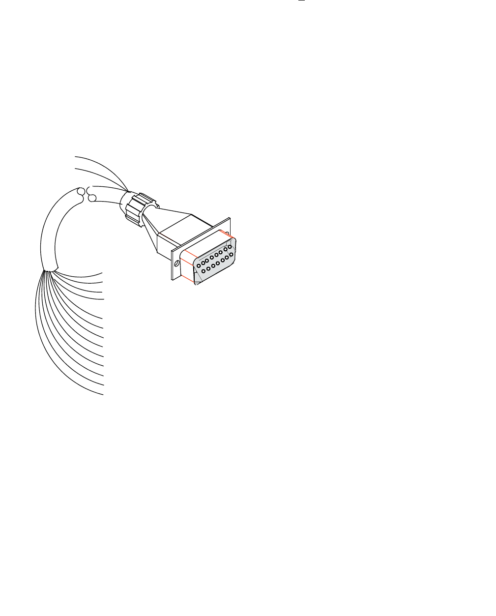
Figure 2-2 JSLM2 Accessory Interconnect Power Cable
5 BLU/BLK
3 BLU/WHT
2 RED/WHT
1 WHT/BLK Dot
9 GRN/BLK
10 ORN/BLK
11 RED/BLK
12 ORANGE
13 BLK/WHT Dot
14 WHITE
6 RED
15 BLACK
4 GRN/WHT
7 GREEN
8 BLUE
3-1
Part No. 001-2100-101
SECTION 3
PROGRAMMING
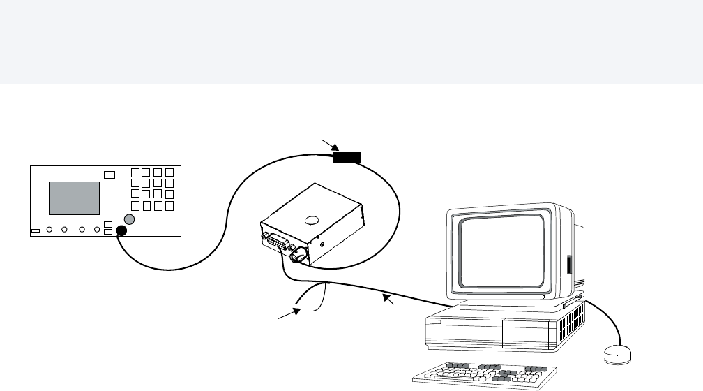
Figure 3-1 JSLM2 Field Programming Software Setup
3.1 INTRODUCTION
3.1.1 GENERAL
Section 3 describes the use of the Field Programming Software used to configure and test the JSLM2 transceiver.
Mechanical adjustments for frequency, deviation and audio levels are described in Section 4 (Alignment and
Troubleshooting). This information is designed for use by installation personnel. Radio adjustments described in
this section should be done by technicians familiar with radio shop procedures.
3.2 JSLM2 FIELD PROGRAMMING SOFTWARE
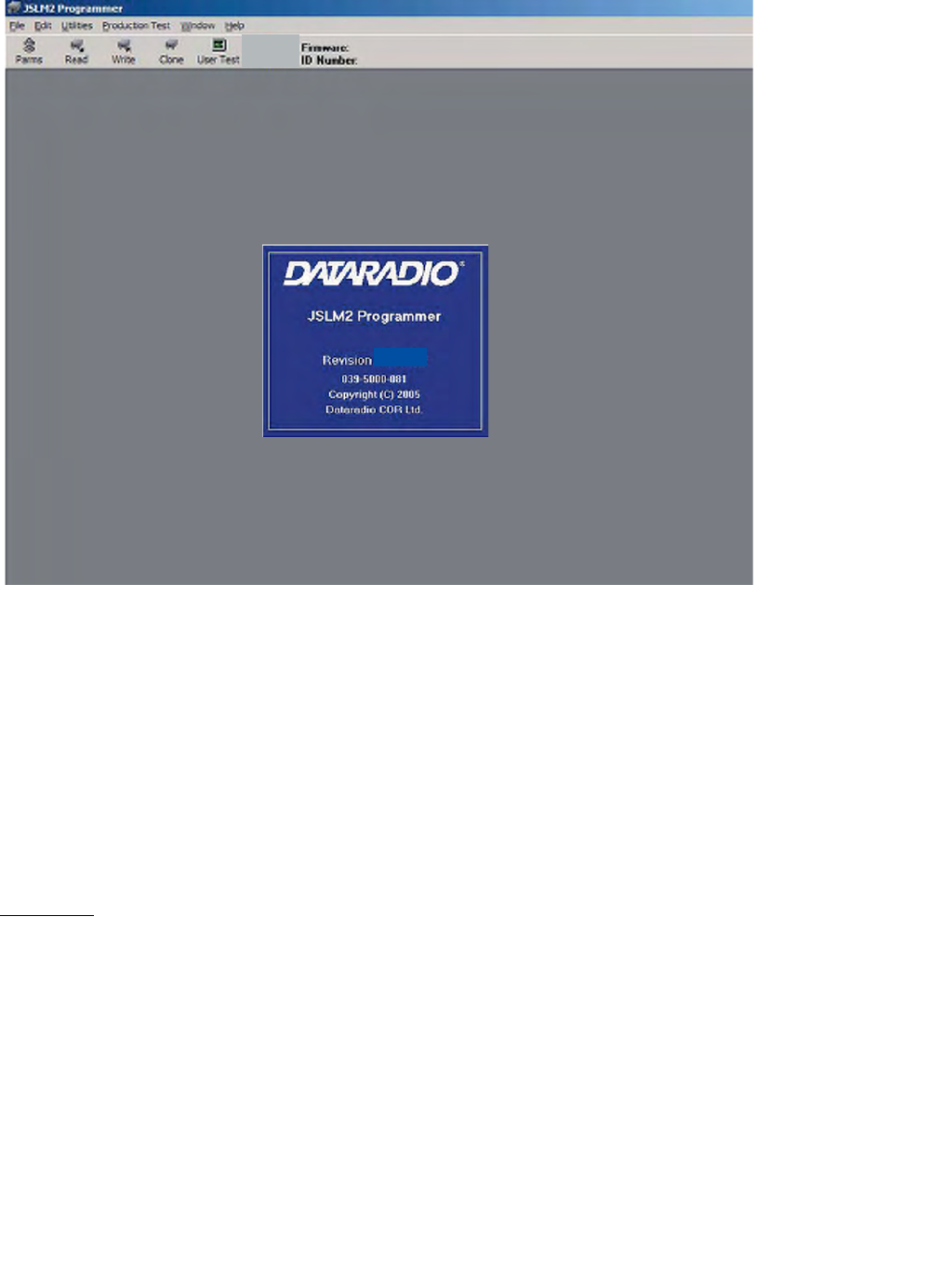
3.2.1 INTRODUCTION
The JSLM2 Programmer is the Field Programming Software for tuning and programming the Dataradio JSLM2
series data transceiver (see Figure 3-2). The Field Programming Software helps the user:
zEdit and program the programmable settings for the JSLM2 transceiver
zChange the transmit and receive frequencies
zMonitor diagnostic data from the JSLM2
Attenuator
Set-up
Cable
JSLM2
6-15VDC
Spectrum Analyzer
3-2
Part No. 001-2100-101
Figure 3-2 JSLM2 Field Programming Software Start-up Screen
3.2.2 RADIO PARAMETERS
The Setup JSLM2 Parameters screen allows the user to view and edit the JSLM’s programmable parameters (see
Figure 3-3). The programmable parameters can be stored in a data file with the .DAT file extension by selecting
“Save Data File” from the file menu. These programmable parameters are used by the Read/Write Parameters
screen for programming into nonvolatile memory of the JSLM2.
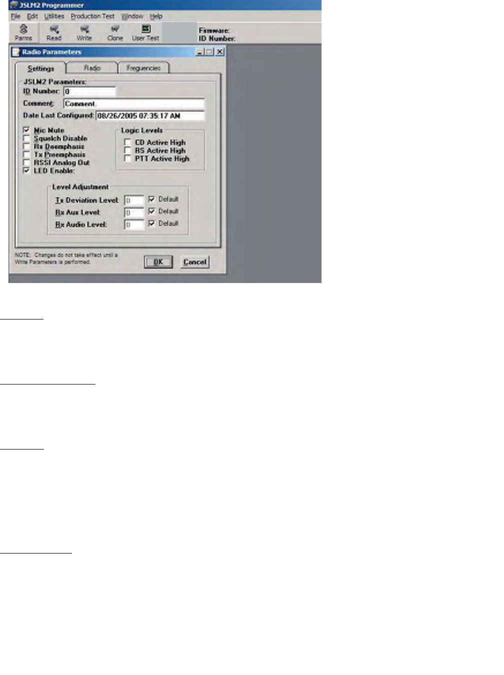
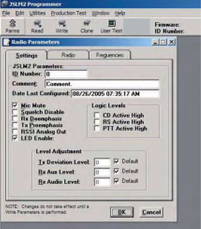
3.2.2.1 SETTINGS TAB
The Settings tab allows the user to program various JSLM2 operating parameters (see Figure 3-3).
ID Number
The ID Number is customer programmable from 0 to 4294967295.
NOTE: This ID is not the same as the printed serial number. Use the printed serial number to identify the unit’s
warranty status.
3-3
Part No. 001-2100-101
Figure 3-3 Setup JSLM2 Parameters - Settings Tab
Comment
The Comment field can be used as a notepad (customer name, location, technical information...) for text up to 40
characters in length (including spaces).
Date Last Configured
Date Last Configured shows the date the JSLM2 was last programmed. The date is taken from the operating
system. No entry is allowed in this field.
Mic Mute
Mic Mute allows the user to enable or disable the microphone audio input. The default for MIC input is enabled
(box checked) to prevent stray noise pickup.
MIC Input (J204, Pin 4) is passed through a separate audio path that has 300-3000 Hz filtering and a 6 dB per
octave pre-emphasis response before the limiter.
Squelch Disable
Squelch Disable allows the user to squelch audio outputs. The default for Squelch Disable is box checked
(enabled) - the audio outputs are always un-squelched. When disabled (box un-checked), the audio outputs are
squelched and un-squelch on Carrier Detect.

3-4
Part No. 001-2100-101
Rx De-emphasis
Since data equipment normally requires a flat audio response, the default value for Rx De-emphasis is disabled
(unchecked). With Rx De-emphasis disabled, the JSLM2 provides a 300 - 2500 Hz +1/-3 dB flat audio response.
When the Rx De-emphasis is enabled (checked), data output is passed through a 300 Hz - 3000 Hz filter and a 6 dB
per octave de-emphasis response.
Tx Pre-Emphasis
Since data equipment normally requires a flat audio response, the default value for Tx Pre-emphasis is disabled
(unchecked). With Tx Pre-Emphasis disabled, the JSLM2 provides a 300 - 2500 Hz +1/-3 dB flat audio response
before the limiter. When Tx Pre-Emphasis is enabled (box checked), the JSLM2 provides 300-3000 Hz filtering
and a 6 dB per octave pre-emphasis response before the limiter.
RSSI Analog Out
The default value for the RSSI Analog Out is disabled (unchecked) which provides Squelch Disable (from J204,
Pin 11). When the RSSI Analog Out is enabled (checked), J204 - Pin 11 is switched from Squelch Disable to a
Receive Signal Strength Indicator (RSSI) DC voltage.
LED Enable
The default value for LED Enable is enabled (box checked). If unchecked, the LEDs are disabled.
Logic Levels
Logic Levels allows the user to select the polarity of some pins on the data interface connector. The Carrier Detect
(CD), Ready to Send (RS) and Push to Talk (PTT) polarity is programmable as Active High or Active Low.
Level Adjustment
Level Adjustment allows the user to program the Transmit Deviation Input, Rx Aux Out and Rx Audio Out levels.
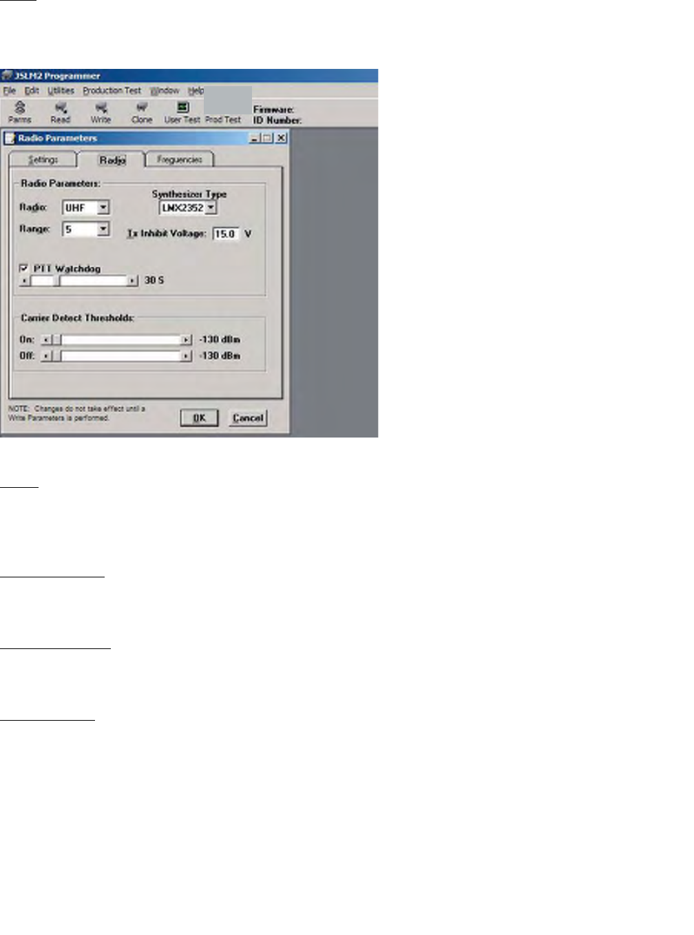
3.2.2.2 RADIO TAB
The Radio tab allows user programming of radio operating parameters.
Table 3-1 LED Functions
Color Indicates
Continuous Green Unit has DC power
Continuous Red Unit is transmitting
Continuous Amber Unit has Receive Carrier Detect
Flashing Green Unit DC power exceeds 15 Vdc
Flashing Red Unit internal temperature exceeded 85 degrees C
Flashing Amber Unit VCO/synthesizer is unlocked
3-5
Part No. 001-2100-101
Radio Parameters
Radio
The Radio drop-down box shows the type JSLM2 (UHF or VHF). The Radio type is uploaded from the JSLM2 or
from an opened file. No entry is allowed in this field.
Figure 3-4 Setup Radio Parameters Screen
Range
The Range drop down box shows the frequency range of the JSLM2. The frequency range is uploaded from the
JSLM2 or from an opened file. No entry is allowed in this field.
Synthesizer Type
Shows the synthesizer type for the JSLM2. No entry is allowed in this field.
Tx Inhibit Voltage
Tx Inhibit Voltage shows the maximum voltage level for transmitter key up. No entry is allowed in this field.
PTT Watchdog
The default for PTT Watchdog is enabled (box checked). PTT Watchdog range is 1 - 120 seconds selectable by
moving slider bar. When disabled (unchecked), the transmitter can transmit up to 5 minutes before a firmware
shutdown is invoked.
3-6
Part No. 001-2100-101
Carrier Detect On Threshold
Carrier Detect On Threshold indicates the RSSI level for a received carrier. The Carrier Detect On Threshold value
should be greater than (a less negative number) the Carrier Detect Off Threshold value.
Carrier Detect Off Threshold
Carrier Detect Off Threshold indicates the RSSI level for a lost carrier. The Carrier Detect Off Threshold value
should be less than (a larger negative number) the Carrier Detect On Threshold value.
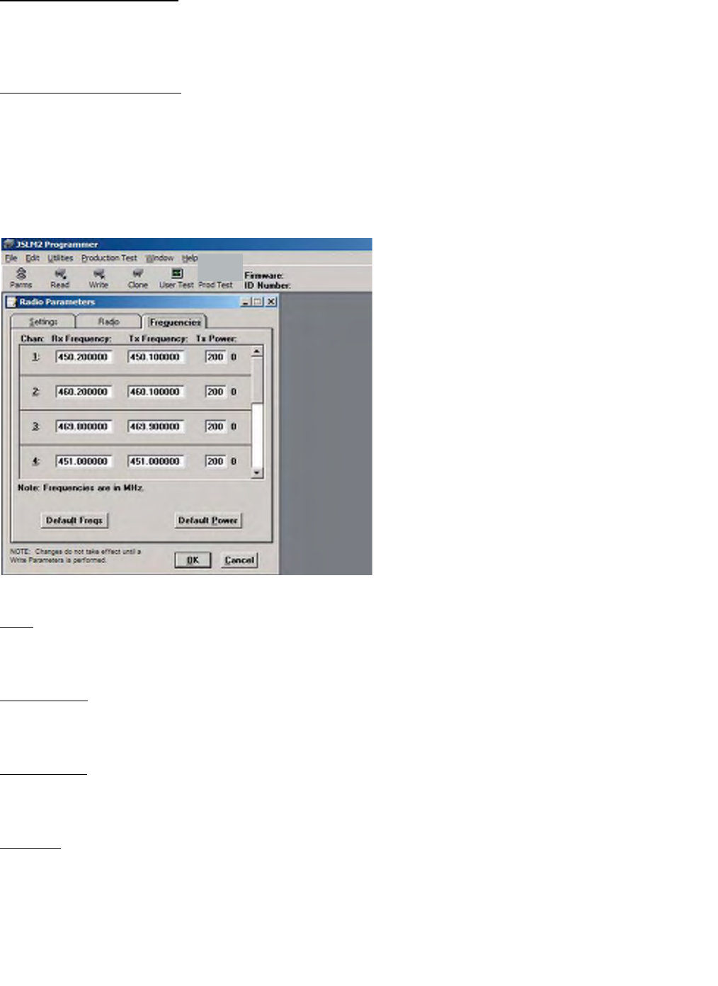
3.2.2.3 FREQUENCIES TAB
The Frequencies tab is used for user programming of the eight frequency pairs.
Figure 3-5 Setup Frequencies Screen
Chan
Chan displays the frequency channel pair.
Rx Frequency
Rx Frequency displays the receive frequency for the channel pair (in MHz).
Tx Frequency
Tx Frequency displays the transmit frequency for the channel pair (in MHz).
Tx Power
Tx Power allows the user to vary the power output setting of the transmitter.
3-7
Part No. 001-2100-101
Default Freqs
The Default Freqs button returns the Rx and Tx frequencies to default values. The default frequencies are based on
radio type and range.
Default Power
The Default Power button allows the user to return the Tx Power to factory power output settings.
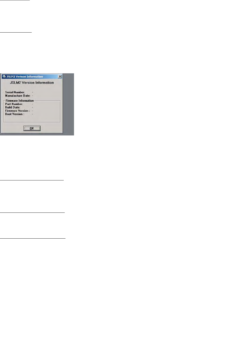
3.2.3 VERSION REQUEST
Figure 3-6 JSLM2 Version Request
Version Request displays JSLM2 hardware and firmware version information.
3.2.4 READ/WRITE PROGRAMMABLE SETTINGS
Read Programmable Settings
Read Programmable Settings reads and displays the programmable settings currently programmed in the
EEPROM of the JSLM2.
Write Programmable Settings
Write Programmable Settings writes the currently loaded settings to the EEPROM of the JSLM2.
Clone Programmable Settings
Clone Programmable Settings clones (writes) the currently loaded programmable settings (except ID Number and
Comment) to the EEPROM of the JSLM2. Clone Programmable Settings is used to program a Data File (.DAT) to
multiple JSLM2s.
3-8
Part No. 001-2100-101
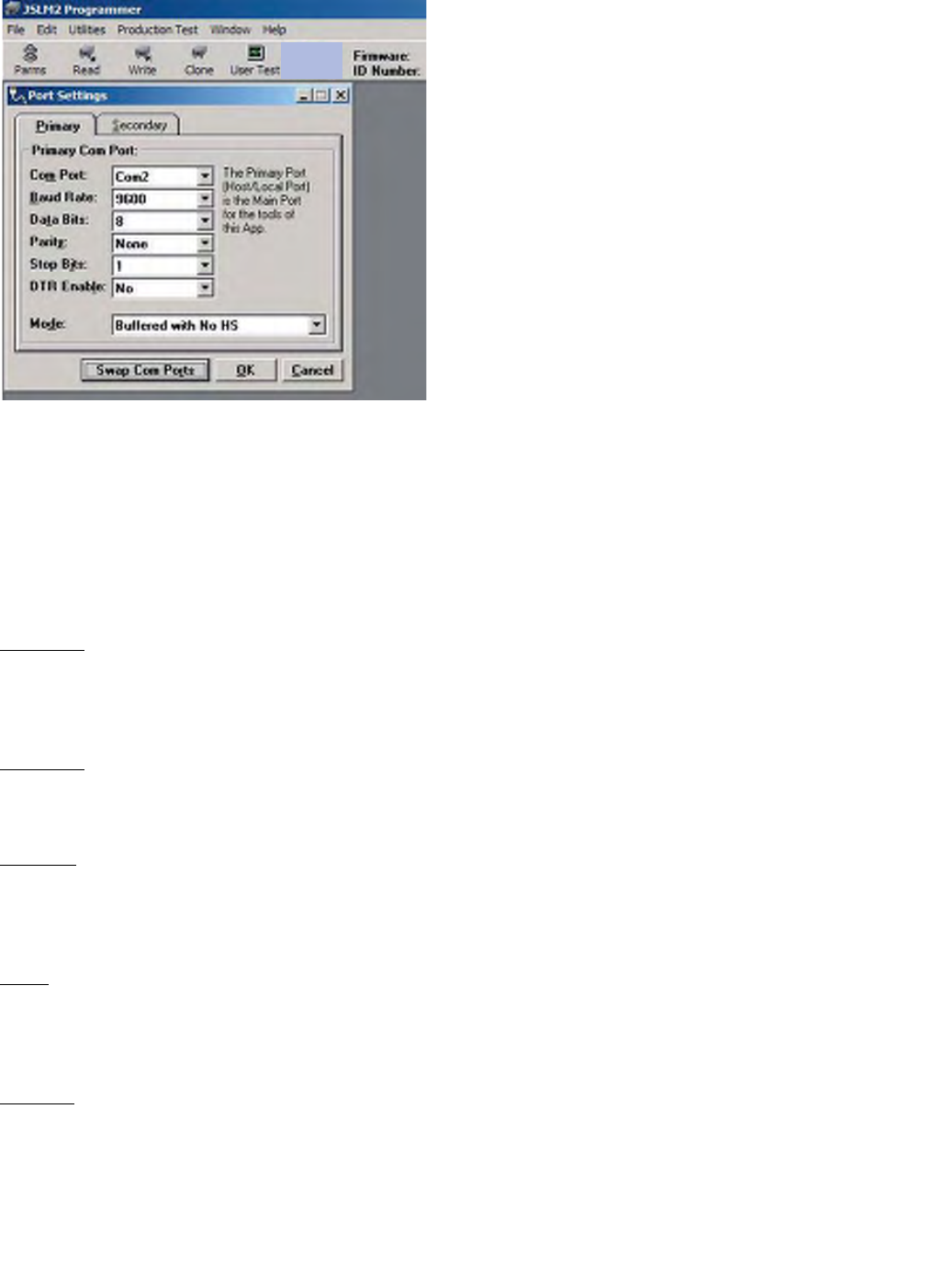
Figure 3-7 Serial PC Port Settings Screens
3.2.5 PORT SETTINGS
Port Settings are used to configure the user PC’s serial COM ports (Primary and Secondary). Port Settings can be
used to test data links using the ASCII and HEX terminals (available in the Utilities menu). The JSLM2 Field
Programming Software will override these settings when using any other screen to communicate with the JSLM2.
NOTE: A modem is required to transmit serial data using this program. The JSLM2 is an analog signal device.
COM Port
The COM Port field allows the user to select the COM port number (1-4) for the Primary and Secondary COM
port.
Baud Rate
The Baud Rate field allows the user to select the communication speed for the Primary and Secondary COM ports.
Data Bits
The Data Bits field allows the user to select the number of Data Bits (4 - 8) to transmit or receive over the Primary
and Secondary COM ports.
Parity
The Parity field permits the user to select Parity Bits (None/Odd/Even) to transmit or receive for the Primary and
Secondary COM ports.
Stop Bits
The Stop Bits field permits the user to select the number of Stop Bits (1 or 2) to transmit or receive for the Primary
and Secondary COM Ports.

3-9
Part No. 001-2100-101
DTR Enable
The DTR field allows the user to select whether the DTR (Data Terminal Ready) line of the RS-232 port is
asserted when the port is open for the Primary and Secondary COM ports.
Mode
Mode allows the user to select the communications mode for the Primary and Secondary COM ports. See Table 3-
2 for available modes.
Sync/Esc Framing
A typical Sync/Esc frame resembles the following character stream:
SYNC ML Data0 --- DataN Chksum
8 bits 8 bits 8 bits --- 8 bits 8 bits
with the following definitions made:
Sync (8 bits) - marks the start of a frame when not preceded by an ESC character. When using a Sync/Esc
(Framing) Mode, the Field Programming Software will stuff this character automatically.
ML (8 bits) - the length of the frame. ML is the number of characters left to be received including the checksum
but excluding any ESC characters added as part of the protocol. When using a Sync/Esc (Framing) Mode, the Field
Programming Software will stuff this character automatically based on the number of Data Characters.
Data 0 - N(8 bits each) - frame information
Chksum (8 bits) - the 8 bit 2s complement of the sum of the frame less the SYNC character and any additional
ESC added characters ignoring the carryout of the high order bits. When using a Sync/Esc (Framing) Mode, the
Field Programming Software will stuff this character automatically.
Table 3-2 Communications Modes
Mode Description
Sync/Esc with No HS Send data using the Sync/Esc byte-stuffing protocol with no handshaking
Buffered with No HS Send buffered data without handshaking
Sync/Esc with RTS/CTS HS Send data using the Sync/Esc byte-stuffing protocol with RTS/CTS
hardware handshaking
Buffered with RTS/CTS HS Send buffered data with RTS/CTS hardware handshaking
Sync/Esc with Flow Control HS Send data using the Sync/Esc byte-stuffing protocol with flow control
handshaking
Buffered with Flow Control HS Send buffered data with flow control hardware handshaking
3-10
Part No. 001-2100-101
Swap COM Ports
Swap COM Ports allows the user to swap the Primary and Secondary COM ports. For example, if the Primary is
COM1 and the Secondary is COM2, the Primary becomes COM2 and the Secondary becomes COM1 after a Swap
COM Ports is issued. This utility is useful when more than one JSLM2 is connected to a PC since the programming
screens all use the Primary COM port. By issuing a Swap COM Ports, the JSLM2 connected to the second COM
port can be programmed without switching cables.
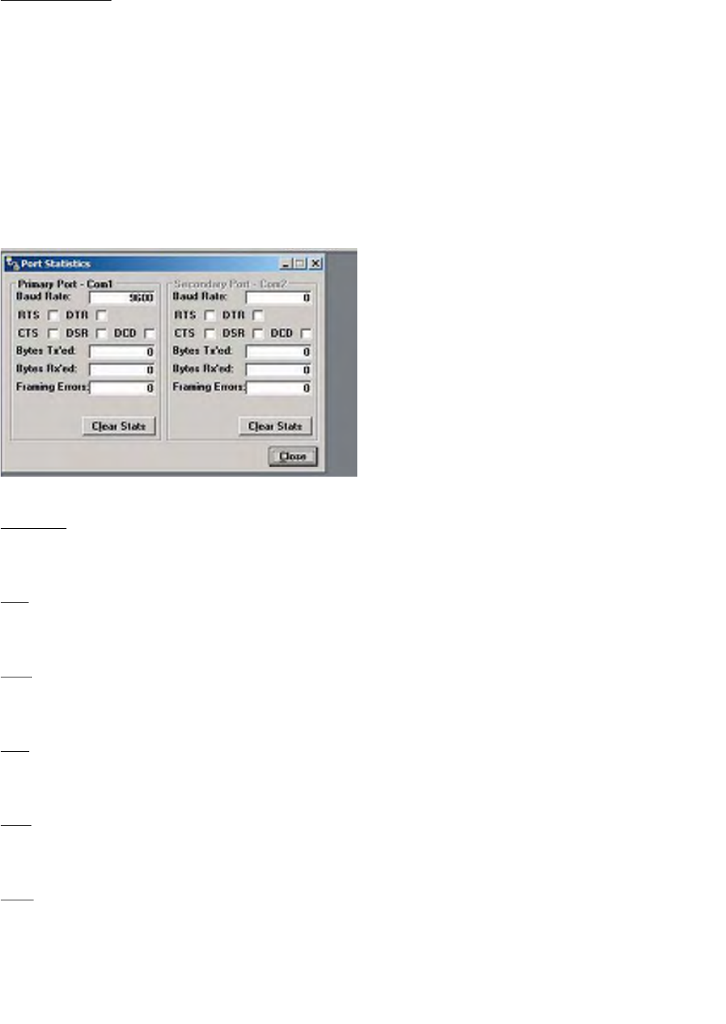
3.2.6 PORT STATISTICS
The Port Statistics utility shows some of the statistics of the PC’s serial COM ports (Primary and Secondary). (A
check in the check box indicates an active state).No entry is allowed in these fields.
Figure 3-8 Serial PC Port Statistics Screen
Baud Rate
Baud Rate displays the baud rate of the transmitter.
RTS
The RTS field shows the current state of the RTS (request-to-send) line. RTS is an output from the PC.
DTR
The DTR field shows the current state of the DTR (data-terminal-ready) line. DTR is an output from the PC.
CTS
The CTS field shows the current state of the CTS (clear-to-send) line. CTS in an input to the PC.
DSR
The DSR field shows the current state of the DSR (data-set-ready) line. DSR is an input to the PC.
DCD
The DCD field shows the current state of the DCD (data-carrier-detect) line. DCD in an input to the PC.
3-11
Part No. 001-2100-101
Bytes Tx’ed
The Bytes Tx’ed field shows the number of bytes (characters) transmitted since the port was last opened.
Bytes Rx’ed
The Bytes Rx’ed field shows the number of bytes (characters) received since the port was last opened.
Framing Errors
The Framing Errors field shows the number of Framing Errors received since the port was last opened.
Dribble Bytes
The Dribble Bytes field shows the number of extra (not expected) bytes (characters) received since the port was
last opened.
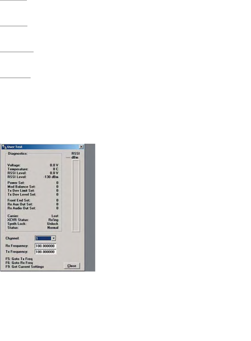
3.2.7. USER TEST
The User Test Utility allows the user to test the functionality of the JSLM2. This utility makes diagnostic
information available and gives the user the ability to change channels and transmit or receive a modulated signal.
Figure 3-9 JSLM2 User Test Screen

3-12
Part No. 001-2100-101
Diagnostic parameters include:
Voltage - Supply voltage (in volts)
Temperature - Internal case temperature (in Celsius)
RSSI Level - Received Signal Strength indicator (in volts)
RSSI Level - Received Signal Strength indicator (in dBm)
Power Set: Transmitter power digipot setting
Mod Balance Set: Transmitter modulation balance digipot setting
Tx Dev Limit Set: Transmitter devation limit digipot setting
Tx Dev Level Set: Transmitter deviation level digipot setting
Front End Set: Displays receive front end digipot setting (VHF module only)
Rx Out Set: Receive auxiliary output digipot setting
Rx Audio Out Set: Receive audio output digipot setting
Carrier: Indicates lost or found Recieve Carrier
XCVR Status - State of transceiver (receiving or transmitting)
Synth Lock - Indicates VCO/Synthesizer “lock” or “unlock”
Status: Indicates Over Voltage, Over Temp or Voltage/Temp (if both conditions exceeded)
RSSI
The RSSI panel shows the current RSSI (received signal strength indicator) level (in dBm) while the local unit is
receiving.
Channel
The Channel field allows the user to select one of the 8 programmed channels for the unit’s use.
Rx/Tx Frequency
The Rx and Tx Frequency fields display the current receive and transmit frequencies.
F5
Pressing the F5 key causes the unit to transmit on the programmed transmit frequency.
F6
Pressing the F6 key causes the unit to go to receive on the programmed receive frequency.
F9
Pressing the F9 key causes the programmer to read the current settings from the module.
3-13
Part No. 001-2100-101
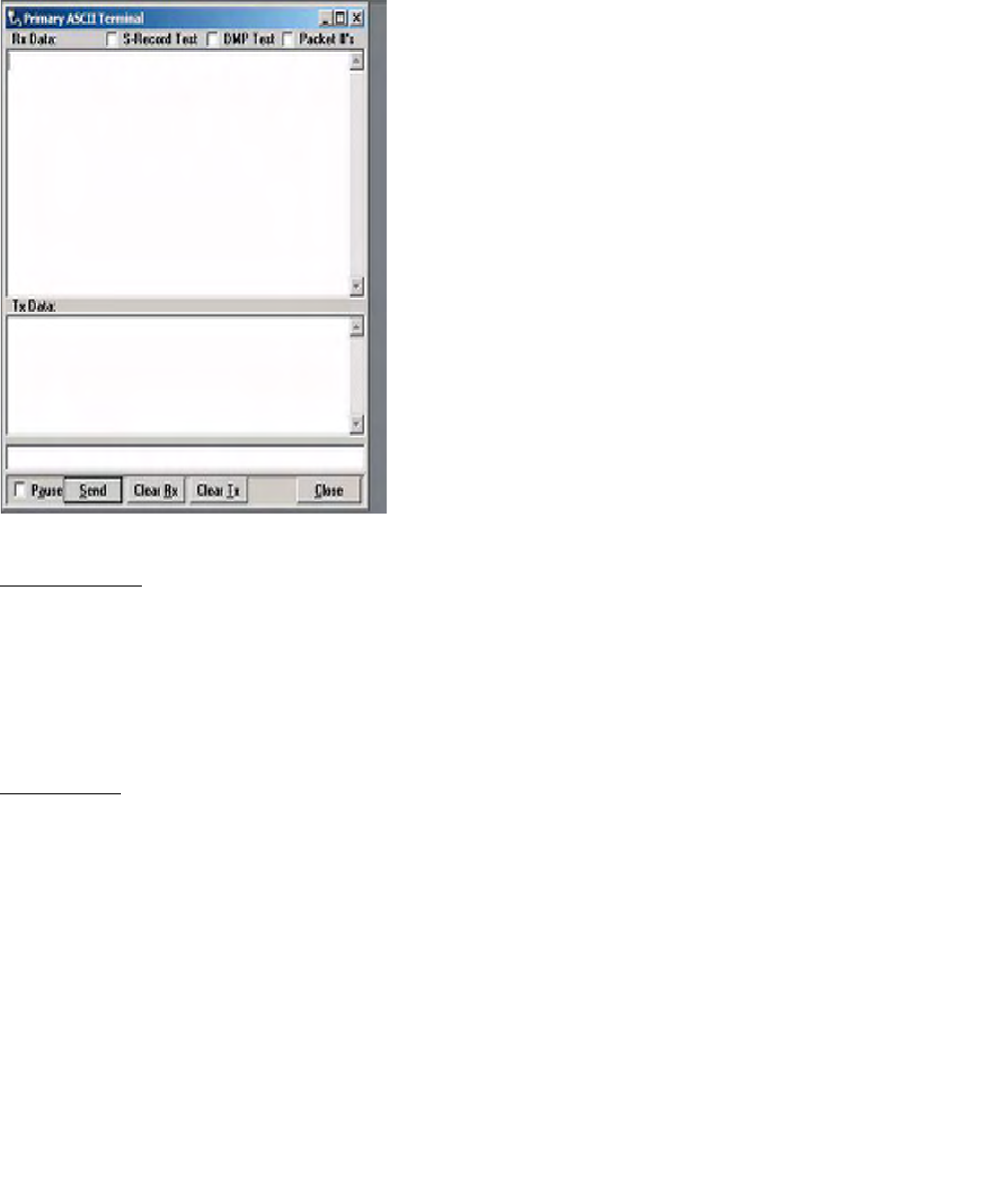
3.2.8. ASCII / HEX TERMINAL
The Terminal Screens allow the user to select an ASCII or Hexadecimal Terminal Screen for the Primary and
Secondary COM ports that were configured in the Port Settings screen. The data is sent according to the port
configuration (setup in the Port Settings screen). NOTE: A modem is required to utilize this feature.
Figure 3-10 ASCII Terminal Screen
ASCII Terminal
Primary - selects an ASCII Terminal screen to send and receive ASCII data on the Primary COM port (setup the
Port Settings).
Secondary - selects an ASCII Terminal screen to send and receive ASCII data on the Secondary COM port (setup
in Port settings).
Hex Terminal
Primary - selects a Hexadecimal Terminal screen to send and receive Hexadecimal data on the Primary COM port
(setup the Port Settings).
Secondary - selects a Hexadecimal Terminal screen to send and receive Hexadecimal data on the Secondary COM
port (setup in Port settings).
3.3 JSLM2 FIELD PROGRAMMING SOFTWARE HELP FILES
JSLM Field Programming Software’s online help files are accessed by the menu bar at the top of the Field
Programming Software window.

SECTION 4
ALIGNMENT AND TROUBLESHOOTING
4-1
Part No. 001-2100-101
4.1 GENERAL
4.1.1 PERIODIC CHECKS
This module should be put on a regular maintenance schedule and an accurate performance record maintained.
Important checks are receiver sensitivity, transmitter frequency, modulation, and power output. It is recommended
that module performance be checked annually even though periodic checks are not required by the FCC. Section 4
outlines these tests.
4.1.2 SERVICING
The majority of the components used on the printed circuit boards are surface mount devices. JSLM2 module
component level field repair is not recommended. Specialized training and equipment are required to service board
level components. Equipment should be returned to the factory for repair.
4.2 PERFORMANCE CHECKS
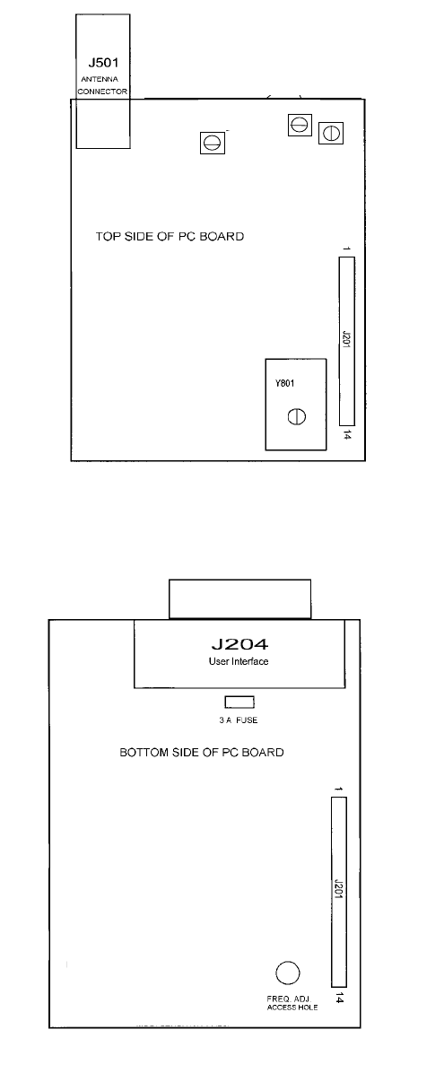
4.2.1 CHANNEL FREQUENCY
The module frequency is controlled by a temperature compensated crystal oscillator (DCXO) which has a
frequency stability of ± 1.5 parts per million over a temperature range of -30 to + 60° C. When transmitting (for
example) at 450 MHz, the output frequency should be 450 MHz ± 675 Hz over temperature. The operating
frequency may be adjusted through the case of the JSLM2. Connect the User Interface Cable included in the
JSLM2 Field Programming Kit (part number: 250-2100-001). Connect the antenna port to a frequency counter or
other frequency measurement instrument. Locate the Frequency Adjust Access Hole on the bottom side of the
Loader Board (see Figure 4-2). Enable the transmitter PTT Line and use a small screwdriver to adjust the DCXO
for the desired transmit frequency.
Caution: An RF attentuator may be required depending on the power handling capability of the measuring
instrument.
4.2.2 RF OUTPUT POWER
The RF output power may be verified with an accurate power meter connected with a short 50 ohm cable to the
Antenna Connector. See Section 1, General Specifications for module specifications. Transmitter alignment is
performed in the factory and is not a recommended field adjustment.

4-2
Part No. 001-2100-101
4.2.3 TRANSMIT DEVIATION
Transmit deviation is preset at the factory. It is adjustable utilizing the JSLM2 Field Programming Software. Select
Parameters Settings/Transmit Deviation Level. The value is changed by:
1. Un-check the Default box
2. Highlight the value
3. Change the value
a. Increment by 1 using the Arrow Up/Arrow Down keys
b. Increment by 10 using the Page Up/Page Down keys
After changing the Transmit Deviation Level, a Write must be performed to the JSLM2 transmitter. To return to the
factory default level, check the Default box and perform a Write to the JSLM2 transmitter.
4.2.4 TRANSMIT DEVIATION LIMITING
Transmit Deviation Limiting is preset at the factory to 2.20 +.10 kHz and is not field programmable. Deviation
Limiting may be checked by injecting a 1000 Hz tone at 1.0 Vrms to the Aux Input or Mic Input.
4.2.5 RECEIVE AUX OUT AND AUDIO OUT LEVELS
Receive Aux Out and Audio Out levels are preset by the factory. Refer to General Information, Section 1, for
specifications and levels. These levels are adjustable utilizing the JSLM2 Field Programming Software. Select
Parameters Settings/Rx Aux Level or Rx Audio Level. Values are changed by:
1. Un-check the Default box
2. Highlight the value
3. Change the value
c. Increment by 1 using the Arrow Up/Arrow Down keys
d. Increment by 10 using the Page Up/Page Down keys
After changing the Receive Aux Out or Audio Out Level, a Write must be performed to the JSLM2 transmitter. To
return to the factory default level, check the Default box and perform a Write to the JSLM2 transmitter.
4.3 TROUBLESHOOTING
PROBLEM
Radio Inoperative
CHECK
zVerify the DC power source is properly connected.
zVerify DC power source is set at the correct voltage.
zCheck the fuse on the Loader Board (see Figure 4-2).
4-3
Part No. 001-2100-101
PROBLEM
No/Poor Transmit
CHECK
zVerify power supply voltage.
zVerify power supply voltage can source 2000 mA minimum.
zVerify proper programming including frequency and time-out-timer.
zCheck system VSWR, feedline loss, connectors, and antenna.
zCheck radio output power with wattmeter.
PROBLEM
No/Poor Receive
CHECK
zVerify Power Supply voltage.
zVerify proper receive frequency programming.
zCheck feedline loss, connectors and antenna.
zApply -100 dBm RF signal at antenna connector and check RSSI indicator in User Test utility.
zVerify that the channel is unoccupied.
4-4
Part No. 001-2100-101
C554, C527 Transmit Tuners
DCXO
Figure 4-1 JSLM2 RF Board Adjustment Points
Figure 4-2 JSLM2 Loader Board Frequency Adjustment Access
Appendix A
Technical Support Application Note
A-1
001-2100-101
Technical Support Application Note
#0600003
Dataradio COR Ltd.
USA 800-992-7774; International 507-833-8819
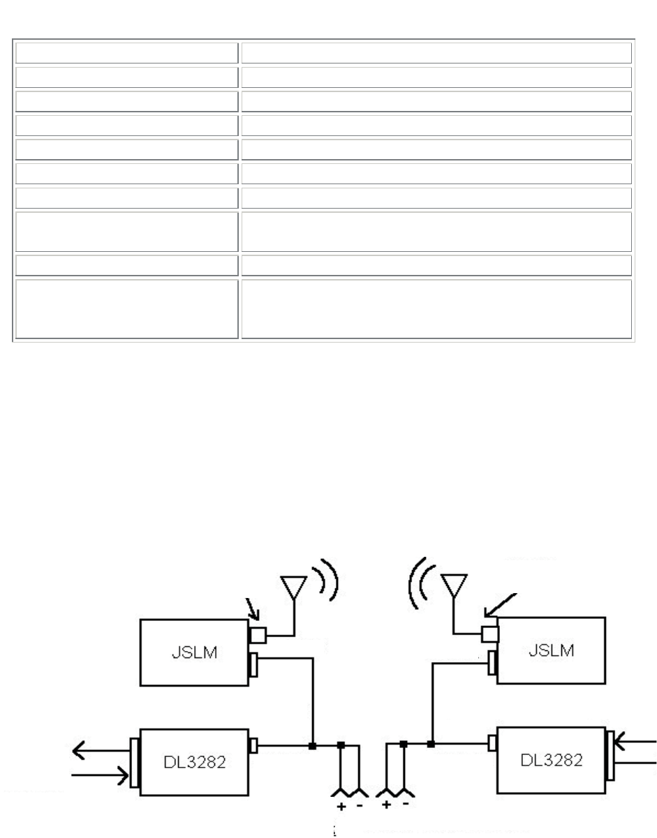
Product: JSLM2 module – DL-3282 Bell 103, Bell 202 Modem Configuration
Application:
To provide technical information for connecting a JSLM2 analog module with a DL-3282 RS-232
Modem. The JSLM2 module family is designated as part number 242-2040-XXX for UHF models.
The DL-3282 Modem is part number 250-3282-002 and is available as Bell 202 or Bell 103 format.
Combined with an interface cable (part number 697-3414-003), the module and modem will provide a
reliable 300 baud or 1200 baud RS-232 serial Dataradio system.
Setup:
DL-3282 Modem: The DL-3282 modem does not require special programming for normal Bell 202 or
Bell 103 format. All data parameters are set using an eight-position DIP switch located inside the
modem.
Programming:
JSLM2 Module – The JSLM2 module is computer programmable using the Windows® based
programming kit (part number 250-2100-001). (The Field Programming Software requires Win-
dows® 95 or better.) This kit includes the programming software (on CD-ROM) and the program-
ming cable. Software upgrades are available on our website at http://www.dataradio.com/
download_form.shtml.
Table 1: DL-3282 Dip Switch Functions
Position Function Factory Default
1. Normal/Loop Normal operation/loopback test mode Off-normal
2. Conventional Normal operation of interfacing to
trunking radio system Off - conventional
3. Bell 202/103 Selects modem format Off – Bell 202
4. Squelch Invert Carrier Detect inversion Off – Active high
5. Half/Full Duplex Duplex mode determination Off – Half
6. Option 1 Self-test mode Off – Self test off
7. and 8.
RTS/CTS Delay
Set RTS/CTS Delay Timer On, On – 240 msec
delay
A-2
001-2100-101
Power to the module is applied through the programming cable using the Red (B+) and Black
(ground) wires. Supply voltage is specified from +6.0VDC to +15 VDC. Nominal operating voltage is
+7.2 VDC or +12.5 VDC.
Dataradio recommends storing the programming software on the hard drive of the computer. When
the program is loaded, click on the “Read” button to read the unit’s current programming. Click on
“Parms” and select the appropriate tab (Settings, Radio or Frequencies) to make settings as required.
NOTE: If your application requires one frequency pair, Dataradio recommends all channel locations
be programmed with the same frequencies.
A-3
001-2100-101
Clicking OK will close the Settings (or Radio, Frequencies) window and save current settings to local
memory. A Write must be performed to program settings to the JSLM2.
Connections:
Connection between the JSLM2 and DL-3282 is made with the interface cable (697-3414-003).
Table 2: Recommended JSLM
2
Programming Settings (for interfacing with
DL-3282 Modem)
CD – Carrier Detect Active high (Settings tab)
RS – Ready to Send Active high (Settings tab)
PTT – Push to Talk Active low (Settings tab)
Mic Mute On (Settings tab)
Squelch Disable Off (Settings tab)
Rx De-emphasis Off (Settings tab)
Tx Pre-emphasis Off (Settings tab)
RNET Xtal Compatibility
Mode Off (Settings tab)
PTT Watchdog Optional (Radio tab Revs A - I)
Carrier Detect On: -110 dBm; Off: -115 dBm Carrier Detect
settings are selected to optimize the system
based on Receive Signal Strength. (Radio tab)
Figure 1 Typical JSLM
–
Modem Configuration and Connection
DA15-F DA15-F
Input +7.2 to +12.5 VDC
BNC-F
RF In/Out BNC-F
RF In/Out
697-3282-012 cable 697-3282-012 cable
DE-15-F DE-15-F
RS-232
DB25-F
B+- Red
Gnd- Black
2
2
2

RF Exposure Compliance Requirements
A-1
001-2100-101
JSLM2 VHF Analog Telemetry Module
FCC Rule: 1.1307, 1.1310, 2.1091 (b) (d), 2.1093
IC Rule: RSS-119 Section 9, RSS-102 Section 2.2
Description of Compliance:
The JSLM2 will be professionally installed in the SCADA (Supervisory Control And Data Acquisition) market and
will be mounted with a fixed RTU (Remote Terminal Unit). A typical installation would use a maximum gain
antenna of 10 dBi mounted on a tower. A minimum separation distance of more than 141 cm must be maintained
between the radiating structure and any person to classify as a mobile under FCC MPE regulations. Note: It is the
responsibility of the user to guarantee compliance with the FCC MPE regulations when operating this device
in a way other than described above.
The calculation for the more stringent specification, a General Population/Uncontrolled Mobile device according to
section 2.1091(b) and section 1.1310 Note 2 is shown below:
Limits for General Population/Uncontrolled Exposure:
Frequency
Range (MHz) Electric Field
Strength (V/m) Magnetic Field
Strength (A/m) Power Density (mW/cm2) Averaging
Time (mins)
0.3-1.34 614 1.63 *(100) 30
1.34-30 824/f 2.19/f *(180/f2) 30
30-300 27.5 0.073 0.2 30
300-1500 --- --- f (MHz)/1500 (MHz) 30
1500-100000 --- --- 1.0 30
Environmental Specification: 0.2 mW/cm2
S = (PG)/(4πR2) (OET Bulletin 65)
Where:
S = Power Density (mW/cm2)
P = Power input to the antenna (mW)
G = Power Gain of the antenna in the direction of interest relative to an isotropic radiator
R = Distance to the center of radiation of the antenna (cm)
Distance Calculation:
R = √((PG)/(4πS))
Typical Antenna Gain: 10.0 dBi 10(10.0 dBi/10) = 10.0
Power input to the Antenna: 37dBm = 10(37dBm/10) = 5000 mW
R = √((5000mW*10.0)/(4π*0.2 mW/cm2)) = 141 cm (Minimum Distance)

A-2
001-2100-101
JSLM2 UHF Analog Telemetry Module
FCC Rule: 1.1307, 1.1310, 2.1091 (b) (d), 2.1093
IC Rule: RSS 119 Section 9, RSS-102 Section 2.2
Description of Compliance:
The JSLM2 will be professionally installed in the SCADA (Supervisory Control And Data Acquisition) market and will
be mounted with a fixed RTU (Remote Terminal Unit). A typical installation would use a maximum gain antenna of 10
dBi mounted on a tower. A minimum separation distance of more than 121 cm must be maintained between the
radiating structure and any person to classify as a mobile under FCC MPE regulations. Note: It is the responsibility
of the user to guarantee compliance with the FCC MPE regulations when operating this device in a way other
than described above.
The calculation for the more stringent specification, a General Population/Uncontrolled Mobile device according to
section 2.1091(b) and section 1.1310 Note 2 is shown below:
Limits for General Population/Uncontrolled Exposure:
Frequency Range
(MHz) Electric Field
Strength (V/m) Magnetic Field
Strength (A/m) Power Density (mW/cm2) Averaging
Time (mins)
0.3-1.34 614 1.63 *(100) 30
1.34-30 824/f 2.19/f *(180/f2) 30
30-300 27.5 0.073 0.2 30
300-1500 --- --- f (MHz)/1500 (MHz) 30
1500-100000 --- --- 1.0 30
Environmental Specification: f(MHz)/(1500 mW/cm2)
406 MHz/(1500 MHz mW/cm2) = 0.27 mW/cm2 (worst case)
S = (PG)/(4πR2) (OET Bulletin 65)
Where:
S = Power Density (mW/cm2)
P = Power input to the antenna (mW)
G = Power Gain of the antenna in the direction of interest relative to an isotropic radiator
R = Distance to the center of radiation of the antenna (cm)
Distance Calculation:
R = √((PG)/(4πS))
Typical Antenna Gain: 10.0 dBi 10(10.0 dBi/10) = 10.0
Power input to the Antenna: 37dBm = 10(37dBm/10) = 5000 mW
R = √((5000mW*10.0)/(4π*0.27 mW/cm2)) = 121 cm (Minimum Distance)

DATA TELEMETRY PRODUCT WARRANTY
Dataradio COR Ltd. ("DRL") warrants to the original purchaser for use
("Buyer") that data telemetry products manufactured by DRL
("Products") are free from defects in material and workmanship and
will conform to DRL's published technical specifications for a period of,
except as noted below, two (2) years from the date of shipment to
Buyer. DRL makes no warranty with respect to any equipment not
manufactured by DRL, and any such equipment shall carry the original
equipment manufacturer's warranty only. DRL further makes no
warranty as to and specifically disclaims liability for, availability, range,
coverage, grade of service or operation of the repeater system
provided by the carrier or repeater operator. Any return shipping
charges for third party equipment to their respective repair facilities
are chargeable and will be passed on to the Buyer.
If any Product fails to meet the warranty set forth above during the
applicable warranty period and is returned to a location designated by
DRL. DRL, at its option, shall either repair or replace such defective
Product, directly or through an authorized service agent, within thirty
(30) days of receipt of same. No Products may be returned without
prior authorization from DRL. Any repaired or replaced Products shall
be warranted for the remainder of the original warranty period. Buyer
shall pay all shipping charges, handling charges, fees and duties for
returning defective Products to DRL or DRL's authorized service agent.
DRL will pay the return shipping charges if the Product is repaired or
replaced under warranty, exclusive of fees and duties. Repair or
replacement of defective Products as set forth in this paragraph fulfills
any and all warranty obligations on the part of DRL.
This warranty is void and DRL shall not be obligated to replace or
repair any Products if (i) the Product has been used in other than its
normal and customary manner; (ii) the Product has been subject to
misuse, accident, neglect or damage or has been used other than with
DRL approved accessories and equipment; (iii) unauthorized alteration
or repairs have been made or unapproved parts have been used in or
with the Product; or (iv) Buyer failed to notify DRL or DRL's authorized
service agent of the defect during the applicable warranty period. DRL
is the final arbiter of such claims.
THE AFORESAID WARRANTIES ARE IN LIEU OF ALL OTHER
WARRANTIES, EXPRESSED AND IMPLIED, INCLUDING BUT NOT
LIMITED TO, ANY IMPLIED WARRANTY OF MERCHANTABILITY OR
FITNESS FOR A PARTICULAR PURPOSE. DRL AND BUYER AGREE
THAT BUYER'S EXCLUSIVE REMEDY FOR ANY BREACH OF ANY OF
SAID WARRANTIES IT AS SET FORTH ABOVE. BUYER AGREES THAT
IN NO EVENT SHALL DRL BE LIABLE FOR INCIDENTAL,
CONSEQUENTIAL, SPECIAL, INDIRECT OR EXEMPLARY DAMAGES
WHETHER ON THE BASIS OF NEGLIGENCE, STRICT LIABILITY OR
OTHERWISE. The purpose of the exclusive remedies set forth above
shall be to provide Buyer with repair or replacement of non-complying
Products in the manner provided above. These exclusive remedies
shall not be deemed to have failed of their essential purpose so long
as DRL is willing and able to repair or replace non-complying Products
in the manner set forth above.
This warranty applies to all Products sold worldwide.
Some states do not allow limitations on implied warranties so the
above limitations may not be applicable. You may also have other
rights which vary from state to state.
EEXXCCEEPPTTIIOONNSS
OONNEE YYEEAARR: Labor to replace defective parts in repeaters or
base stations
TTHHIIRRTTYY DDAAYY: Tuning and adjustment of telemetry radios
NNOO WWAARRRRAANNTTYY: Fuses, lamps and other expendable parts
Effective 01/2004
WIRELESS DATA
Dataradio COR Ltd. 299 Johnson Avenue, Suite 110, Waseca, MN 56093-0833: Tel: (507) 833-8819 or (800) 992-7774; Fax: (507) 833-6748 Visit us on the web at www.dataradio.com