CalAmp Wireless Networks 2422240510 TSLM UHF WIRELESS MODEM User Manual cover
CalAmp Wireless Networks Corporation TSLM UHF WIRELESS MODEM cover
Manual
Synthesized TSLM
Hi-Spec Integrated
Wireless Modem
Synthesized TSLM
Hi Spec Wireless Modem
Installation Manual
December 2005 001-2200-101 Revision 0 © 2005 by Dataradio COR Ltd.
About Dataradio
Dataradio is the leading designer and manufacturer of trusted wireless products and systems for
critical infrastructure applications. Our products have been found at the heart of mobile and
SCADA data networks around the world for over 20 years. Dataradio products include mobile
data products and systems, telemetry devices, integrated wireless modems for fixed point-to-point
and point to multi-point applications and OEM solutions. Our product line is one of the broadest
and most trusted in the industry.
Product Warranty
The manufacturer's warranty statement for this product is available in our manuals or by
contacting COR Ltd. 299 Johnson Avenue, P.O. Box 1733, Waseca, MN 56093-0833. Phone
(507) 833-8819.
www.dataradio.com
Dataradio provides product brochures, case studies software downloads and product information
on our website.
Every effort is taken to provide accurate, timely product information in this technical manual.
Product updates may result in differences between the information provided herein and the
product shipped. The information in this document is subject to change without notice.
Dataradio is a registered trademark of Dataradio, Inc.
SECTION 1 GENERAL INFORMATION
1.1 INTRODUCTION
1.1.1 GENERAL
This installation manual provides information for selecting, installing, operating, and
maintaining the Dataradio TSLM wireless modem.
1.2 FEATURES
The TSLM is a transparent real-time wireless modem designed primarily for SCADA
(Supervisory Control and Data Acquisition) and telemetry use. Features of the TSLM include:
• Data speeds of 4800 to 9600 b/s maximum in half-channels using a standard RS-232
interface
• Built-in 8 channel synthesized radio transceiver for VHF and UHF Power output of 0.10
W to 5 W (software controlled)
• Half duplex or simplex operation
• Transmit control via RTS
• Online diagnostics monitoring
• Offline local and remote diagnostics
• Compatible with Dataradio T-Base for base station or repeater use
• Compatible with any Dataradio Interoperability Standard (DI-OS) equipment including
the T-96S for data rates of 4800 and 9600 b/s.
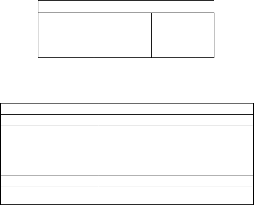
1.3 TSLM PART NUMBER BREAKDOWN
The following table shows the breakdown of the TSLM part number.
Table 1-1 TSLM Part Number Breakdown
242-22W0-XYZ
W X Y Z
1 VHF 6 150-174 MHz
7 137-162 MHz 1
1 12.5 kHz
12.5 kHz 0
0
4 UHF 2 403-422 MHz
2 414-430 MHz
5 450-470 MHz
1
1
1
12.5 kHz
12.5 kHz
12.5 kHz
0
1
0
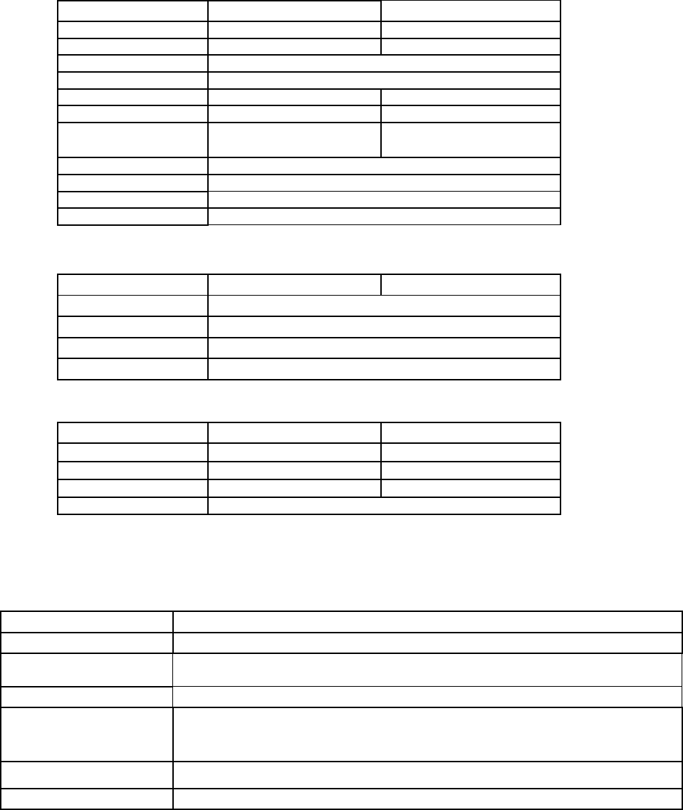
1.4 ACCESSORIES
Table 1-2 TSLM Accessories
Accessory DRL Part Number
Unterminated Power Cable 023-3276-007
DE-15 to DB-9 Power and Data Cable 697-0000-001
Field Programming Kit 250-2200-001
Factory Mutual NI Kit 023-1000-100
Installation Manual for TSLM 001-2200-102 (CD ROM version)
001-2200-101 (Hard Copy version)
DIN Rail Mount 250-4800-406
Switching Power Converter 250-0300-075 (7.5 VDC VOut, 3 Amp)
250-0300-133 (12.5 VDC V Out, 3 Amp)
For information about sales and accessories, contact your sales representative. In the
U.S. phone 1-800-992-7774 or 1-507-833-8819.
1.5 TRANSCEIVER IDENTIFICATION
The transceiver identification number is printed on a label that is affixed to the PC board. The
following information is contained in that number:
Model Revision Manufacturer Warranty
Letter Date Plant Number
22W0 2 A 455 A 12345
Ninth Digit Month Year
of PN
Figure 1-3 Transceiver Identification Nomenclature
1.6 PRODUCT WARRANTY
Dataradio warranties are available in Appendix B and are included in .pdf format on CD
versions of Dataradio manuals.
1.7 FACTORY TECHNICAL SERVICE
The Technical Service Department of Dataradio COR Ltd. (DRL) provides customer assistance
on technical problems and serves as an interface with factory repair facilities. They can be
reached by mail, phone, and email at:
Dataradio COR Ltd. Technical Service Department 299 Johnson Avenue, P.O. Box 1733 Waseca,
MN 56093-0833
1-800-992-7774 or 1-507-833-8819 Fax: 507-833-6748
Email address: support@dataradio-cor.com
Technical Service hours: Monday through Friday 7:30 A.M. to 4:30 P.M. Central Time
1.8 REPLACEMENT PARTS
This product is not field serviceable, except by the replacement of complete units. Specialized
equipment and training is required to repair logic boards and radio modules.
1.9 IF A PROBLEM ARISES...
Component level repair is not recommended on the TSLM. DRL’s factory is best equipped
to diagnose problems and make component level repairs. Contact Technical Service before
returning equipment. A service technician may suggest a solution eliminating the need to
return equipment.
1.9.1 FACTORY REPAIR
Dataradio products are designed for long life and failure-free operation. If a problem arises,
factory service is available. Contact the Technical Service Department before returning
equipment.
A Return Material Authorization (RMA) is required when returning equipment to Dataradio for
repair. Contact the Technical Service Department at 1-800-992-7774 or 1-507-833-8819
(extension 6707) to request an RMA number. RMA’s are available through our website at
www.dataradio.com/ products_tech_adv.html. Be prepared to give the equipment model and
serial number, your account number (if known), and billing and shipping addresses.
Include the RMA number, a complete description of the problem, and the name and phone
number of a contact person with the returned units. This information is important. The
technician may have questions that need to be answered to identify the problem and repair the
equipment. The RMA number helps locate your equipment in the repair lab if there is a need to
contact Dataradio concerning the equipment.
Units sent in for repair will be returned to the customer re-tuned to the current Dataradio Test
and Tune Procedure and will conform to all specifications noted in this section
Customers are responsible for shipping charges (to Dataradio) for returned units in warranty.
Units in warranty are repaired free of charge unless there is evidence of abuse or damage
beyond the terms of the warranty. Dataradio covers return shipping costs for equipment
repaired while under warranty.
Units out of warranty are subject to repair service charges. Customers are responsible for
shipping charges (to and from Dataradio) on units out of warranty. Return shipping instructions
are the responsibility of the customer.
1.10 EQUIPMENT DESCRIPTION
1.10.1 PHYSICAL DESCRIPTION
The TSLM consists of a logic printed circuit board (PCB) (which includes the modem circuitry)
and a separate radio module. The two boards plug directly together, attach to a front panel and
slide into a sheet metal case. The front panel includes a DE-15 data connector, a BNC antenna
connector and two LED indicators. Power connections are made through the DE-15 data
connector. The unit is not hermetically sealed and should be mounted in a suitable enclosure
where dust and/or a corrosive atmosphere are anticipated. There are no external switches or
adjustments. Operating parameters are set using software.
TSLM General Specifications
The following general specifications are subject to change without notice.
GENERAL
VHF UHF
Frequency 137 - 174 MHz 406.2 - 470 MHz
Channel bandwidth 12.5 kHz 12.5 kHz
Operating temperature -30°C to +60°C
Supply voltage 6.00 – 15.0 VDC (applied through the interface connector)
RX Current at 12.5 VDC 180 mA 180 mA
TX Current at 12.5 VDC 2.0 A 2.0 A
RX/TX bandwidth 25 MHz (137 - 162)
24 MHz (150 - 174) 24 MHz (406 - 430)
20 MHz (450 - 470)
Nominal Dimensions 1.02” (H) x 2.45” (W) x 3.63” (L)
Shipping Weight 0.50 lbs (0.23 Kg)
RF connector BNC-F
Interface connector DE-15F high density D-subminiature
RECEIVER*
VHF UHF
Selectivity (12.5 kHz) 60 dB minimum
Intermodulation 70 dB minimum
Spurious rejection 70 dB minimum
Conducted spurious < -57 dBm maximum
TRANSMITTER
VHF UHF
Power output 0.10 - 5 watts 0.10 - 5 watts
Spurious and harmonics -57dBc (-20 dBm) max -57dBc (-20 dBm) max
Frequency stability 1.0 ppm 1.0 ppm
Duty cycle 50% at full power, 30 seconds maximum transmit time
* per TIA 603 with psophometrically weighted filter
MODEM OPERATION
Interface EIA RS-232C
Operation Simplex/half duplex
Data rates 12.5 KHz Channels 4800, 9600 bps
Modulation type DRCMSK
RTS/CTS delay
(Online
diagnostics
OFF)
30 ms
Bit error rate better than 1 x 10 –5 at 1.0 µV at 9600 b/s half channel
Protocol Transparent to the user

PROGRAMMABLE FEATURES
30 second timeout timer enable, bit rate, word length, parity, compatibility modes,
frequency, channel, diagnostics on/off.
FCC / IC CERTIFICATIONS
FCC IC (DOC)
VHF
2422210-001 (9K30F1D)
2984195430A (9K30F1D)
(11K0F1D)
UHF
2422240-001 (9K30F1D)
2984195432A (9K30F1D)
(11K0F1D)
SECTION 2 OPERATION AND CONNECTION
2.1 INTRODUCTION
2.1.1 GENERAL
This section outlines the operation and connections of the TSLM.
2.2 FRONT PANEL
2.2.1 INTRODUCTION
The front panel includes one BNC female antenna connector, two LED indicators and one DE-
15F interface (includes power connections).
2.3 DTE PORT INTERFACE
2.3.1 RS-232 INTERFACE SIGNAL LEVELS
Table 2-2 RS-232 Signal Levels
Term Alternates Signal level
ON asserted, spacing +3 to +15 V
OFF dropped, marking -3 to -15 V
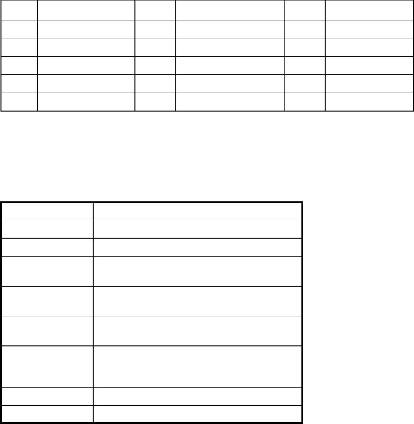
Table 2-3 Modem DE15F Interface Connector Pin Outs
Pin Name Pin Name Pin Name
1 Ground 6 Ground 11 CS 0
2 Rx Data 7 CTS 12 CS 1
3 Tx Data 8 RTS 13 CS 2
4 Test Audio 9 DCD 14 RSSI
5 B+ Power 10 B+ Power 15 DTR_PGM
Note: Table 2-3 is for use with the 023-3276-007 (one end unterminated) if channel
selection control is desired. If not, use 697-0000-001 cable.
2.3.3 INTERFACE SIGNAL DESCRIPTION
Table 2-4 Signal Description
B+ Power (input) 6.00 – 15.0 VDC (12.5V nominal) maximum 2.0A
Rx Data Received Data from TSLM to DTE
Tx Data Transmit Data from DTE to TSLM
CTS Clear to Send. Asserted when the TSLM is ready
to accept Tx data
RTS Request to Send. Causes the TSLM to transmit
when asserted by the DTE.
DCD Data Carrier Detect. Asserted by the TSLM when
a data signal is being received
DTR Data Terminal Ready. Asserted by the Field
Programming Software to select setup mode. Do
not connect to this pin for user applications.
Test Audio Output signal used during adjustment and testing
RSSI Output signal used during testing
In the table, “gnd” indicates that the pin should be connected to ground (Pins 1 or 6)

2.4 CHANNEL SELECTION
Channel frequencies for 8 channels are programmed using the TSLM Field Programming
Software (FPS). Once programmed, the current operating channel may be selected either by:
1.Utilizing hardware jumpers By strapping connections on the Data Port Connector. There is a
10k ohm pull up resistor on each line (CS0 to CS2) (refer to Table 2-5) or making changes with
the TSLM Field Programming Software:
2.By selecting the channel from the TSLM FPS Offline Diagnostics feature.
Table 2-5 Channel Selection
Channel CS2 CS1 CS0
1 gnd gnd gnd
2 gnd gnd open
3 gnd open gnd
4 gnd open open
5 open gnd gnd
6 open gnd open
7 open open gnd
8 open open open
2.5 TSLM FIELD PROGRAMMING SOFTWARE
The TSLM Field Programming Software provides programming and diagnostics for the
Dataradio TSLM wireless modem. The Field Programming Software allows the user to edit and
program user programmable settings, interactively tune modem and RF parameters, and monitor
diagnostic data from the TSLM.
The PTT Watchdog allows the user to set the maximum transmit time. This is used to protect
against a ‘stuck’ transmitter. The time is selected by a slider bar. The range is 0 to 120 seconds
with a default of 30 seconds.

2.6 FCC MPE Compliance Reports - VHF and UHF
RF Exposure Compliance Requirements
TSLM VHF Wireless Modem
FCC Rule: 1.1307, 1.1310, 2.1091 (b) (d), 2.1093
Description of Compliance:
The TSLM will be professionally installed in the SCADA (Supervisory Control And Data
Acquisition) market and will be mounted with a fixed RTU (Remote Terminal Unit). A
typical installation would use a maximum gain antenna of 10 dBi mounted on a tower. A
minimum separation distance of more than 141 cm must be maintained between the
radiating structure and any person to classify as a mobile under FCC MPE regulations.
Note: It is the responsibility of the user to guarantee compliance with the FCC
MPE regulations when operating this device in a way other than described above.
The calculation for the more stringent specification, a General Population/Uncontrolled
Mobile device according to section 2.1091(b) and section 1.1310 Note 2 is shown below:
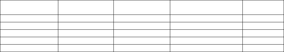
Limits for General Population/Uncontrolled Exposure:
Frequency Range
(MHz) Electric Field
Strength (V/m) Magnetic Field
Strength (A/m) Power Density (mW/cm2) Averaging
Time (mins)
0.3-1.34 614 1.63 *(100) 30
1.34-30 824/f 2.19/f *(180/f2) 30
30-300 27.5 0.073 0.2 30
300-1500 --- --- f (MHz)/1500 (MHz) 30
1500-100000 --- --- 1.0 30
Environmental Specification: 0.2 mW/cm2
S = (PG)/(4πR2) (OET Bulletin 65)
Where:
S = Power Density (mW/cm2)
P = Power input to the antenna (mW)
G = Power Gain of the antenna in the direction of interest relative to an isotropic radiator
R = Distance to the center of radiation of the antenna (cm)
Distance Calculation:
R = √((PG)/(4πS))
Typical Antenna Gain: 10.0 dBi 10(10.0 dBi/10) = 10.0
Power input to the Antenna: 37dBm = 10(37dBm/10) = 5000 mW
R = √((5000mW*10.0)/(4π*0.2 mW/cm2)) = 141 cm (Minimum Distance)
RF Exposure Compliance Requirements
TSLM UHF Wireless Modem
FCC Rule: 1.1307, 1.1310, 2.1091 (b) (d), 2.1093
Description of Compliance:
The TSLM will be professionally installed in the SCADA (Supervisory Control And Data
Acquisition) market and will be mounted with a fixed RTU (Remote Terminal Unit). A
typical installation would use a maximum gain antenna of 10 dBi mounted on a tower. A
minimum separation distance of more than 121 cm must be maintained between the
radiating structure and any person to classify as a mobile under FCC MPE regulations.
Note: It is the responsibility of the user to guarantee compliance with the FCC
MPE regulations when operating this device in a way other than described above.
The calculation for the more stringent specification, a General Population/Uncontrolled
Mobile device according to section 2.1091(b) and section 1.1310 Note 2 is shown below:
Limits for General Population/Uncontrolled Exposure:
Frequency Range
(MHz) Electric Field
Strength (V/m) Magnetic Field
Strength (A/m) Power Density (mW/cm2) Averaging
Time (mins)
0.3-1.34 614 1.63 *(100) 30
1.34-30 824/f 2.19/f *(180/f2) 30
30-300 27.5 0.073 0.2 30
300-1500 --- --- f (MHz)/1500 (MHz) 30
1500-100000 --- --- 1.0 30
Environmental Specification: f(MHz)/(1500 mW/cm2)
406 MHz/(1500 MHz mW/cm2) = 0.27 mW/cm2 (worst case)
S = (PG)/(4πR2) (OET Bulletin 65)
Where:
S = Power Density (mW/cm2)
P = Power input to the antenna (mW)
G = Power Gain of the antenna in the direction of interest relative to an isotropic radiator
R = Distance to the center of radiation of the antenna (cm)
Distance Calculation:
R = √((PG)/(4πS))
Typical Antenna Gain: 10.0 dBi 10(10.0 dBi/10) = 10.0
Power input to the Antenna: 37dBm = 10(37dBm/10) = 5000 mW
R = √((5000mW*10.0)/(4π*0.27 mW/cm2)) = 121 cm (Minimum Distance)
2.6 IC MPE Compliance Reports - VHF and UHF
RF Exposure Compliance Requirements
TSLM VHF Wireless Modem
IC Rule: RSS-119 Section 9, RSS-102 Section 4.2
Description of Compliance:
The TSLM will be professionally installed in the SCADA (Supervisory Control And Data
Acquisition) market and will be mounted with a fixed RTU (Remote Terminal Unit). A
typical installation would use a maximum gain antenna of 10 dBi mounted on a tower. A
minimum separation distance of more than 1.41 meters must be maintained between the
radiating structure and any person to classify as a mobile under IC MPE regulations.
Note: It is the responsibility of the user to guarantee compliance with the FCC
MPE regulations when operating this device in a way other than described above.
The calculation for the more stringent specification, a General Population/Uncontrolled
Mobile device according to RSS 102 Section 4.2 is shown below:
RF Limits for Devices used by the General Public
Frequency
Range (MHz) Electric Field
(V/M rms) Magnetic Field
(A/m rms) Power Density
(W/m2) Time Average (min)
0.003-1 280 2.19 - 6
1-10 280 / ƒ 2.19 / ƒ - 6
10-30 28 2.19 / ƒ - 6
30-300 28 0.073 2* 6
300-1 500 1.585 ƒ 0.5 0.0042 ƒ 0.5 ƒ / 150 6
1 500-15 000 61.4 0.163 10 6
15 000-150 000 61.4 0.163 10 616 000 / ƒ 1.2
150 000-300 000 0.158 ƒ 0.5 4.21 x 10⁻⁴ƒ 0.5 6.67 x 10⁻⁵ƒ 616 000 / ƒ 1.2
Environmental Specification: 2.00 W/m2
S = (PG)/(4πR2)
Where:
S = Power Density (W/m2)
P = Power input to the antenna (W)
G = Power Gain of the antenna in the direction of interest relative to an isotropic radiator
R = Distance to the center of radiation of the antenna (m)
Distance Calculation:
R = √((PG)/(4πS))
Typical Antenna Gain: 10.0 dBi 10(10.0 dBi/10) = 10.0
Power input to the Antenna: 37dBm = 10(37dBm/10) = 5.00 W
R = √((5.00 W*10.0)/(4π*2.00 W/m2)) = 1.41 meters (Minimum Distance)
RF Exposure Compliance Requirements
TSLM UHF Wireless Modem
IC Rule: RSS 119 Section 9, RSS-102 Section 4.2
Description of Compliance:
The TSLM will be professionally installed in the SCADA (Supervisory Control And Data
Acquisition) market and will be mounted with a fixed RTU (Remote Terminal Unit). A
typical installation would use a maximum gain antenna of 10 dBi mounted on a tower. A
minimum separation distance of more than 1.21 meters must be maintained between the
radiating structure and any person to classify as a mobile under IC MPE regulations.
Note: It is the responsibility of the user to guarantee compliance with the FCC
MPE regulations when operating this device in a way other than described above.
The calculation for the more stringent specification, a General Population/Uncontrolled
Mobile device according to RSS 102 Section 4.2 is shown below:
RF Limits for Devices used by the General Public
Frequency
Range (MHz) Electric Field
(V/M rms) Magnetic Field
(A/m rms) Power Density
(W/m2) Time Average (min)
0.003-1 280 2.19 - 6
1-10 280 / ƒ 2.19 / ƒ - 6
10-30 28 2.19 / ƒ - 6
30-300 28 0.073 2* 6
300-1 500 1.585 ƒ 0.5 0.0042 ƒ 0.5 ƒ / 150 6
1 500-15 000 61.4 0.163 10 6
15 000-150 000 61.4 0.163 10 616 000 / ƒ 1.2
150 000-300 000 0.158 ƒ 0.5 4.21 x 10⁻⁴ƒ 0.5 6.67 x 10⁻⁵ƒ 616 000 / ƒ 1.2
Environmental Specification: f(MHz)/(150 W/cm2)
406 MHz/(150 MHz mW/cm2) = 2.71 W/m2 (worst case)
S = (PG)/(4πR2)
Where:
S = Power Density (W/m2)
P = Power input to the antenna (W)
G = Power Gain of the antenna in the direction of interest relative to an isotropic radiator
R = Distance to the center of radiation of the antenna (meters)
Distance Calculation:
R = √((PG)/(4πS))
Typical Antenna Gain: 10.0 dBi 10(10.0 dBi/10) = 10.0
Power input to the Antenna: 37dBm = 10(37dBm/10) = 5.00 W
R = √((5.00 W*10.0)/(4π*2.71 W/m2)) = 1.21 meters (Minimum Distance)