CalAmp Wireless Networks 4018450 Integra VHF Wireless Radio Modem User Manual
CalAmp Wireless Networks Corporation Integra VHF Wireless Radio Modem
User Manual
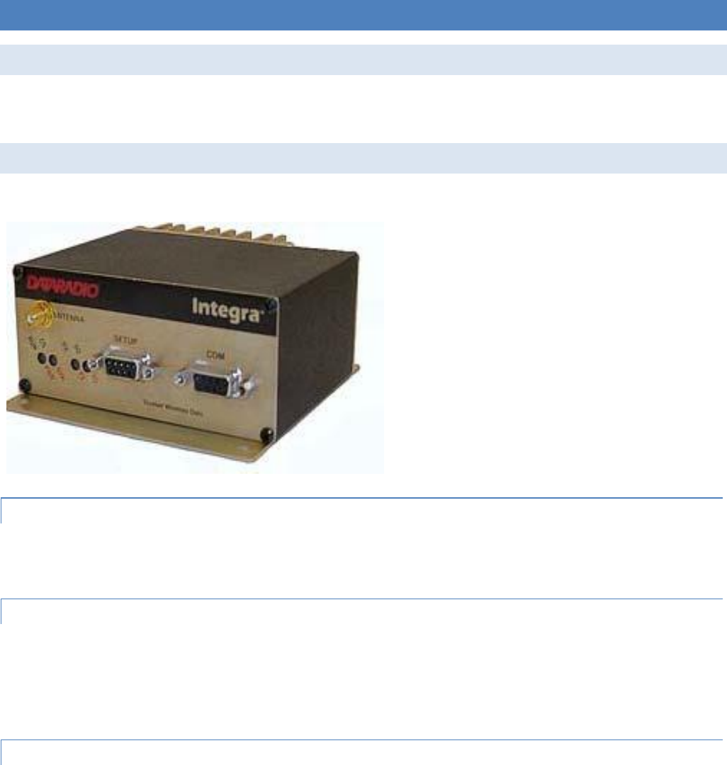
INTEGRA-TR™
WIRELESS MODEM FOR LICENSED SPECTRUM
USER MANUAL
PN 001-4008-000 REV 16
Revised December 2010

REVISION HISTORY
REV
DATE
DESCRIPTION
REV 0
Feb 2000
Initial Release as 001-4008-000.
REV 1
Mar 2000
Updated manual format.
REV 2
Jul 2000
Corrected FCC/IC numbers and added FM approval information.
REV 3
Sep 2000
Updated Channel information in General Specifications - Section 1.
REV 4
Nov 2000
Updated Typical Deviation in Section 4.
REV 5
Jan 2001
Added CE information to Section 1.
REV 6
Mar 2001
Updated Duty Cycle information in General Specifications - Section 1.
REV 7
Jul 2001
Updated manual to reflect Windows-based Field Programming Software to Section 2.
Added Part Number breakdown to Section 1.
REV 8
Oct 2001
Added CSMA and CWID information to Section 2. Moved CD certificates to Appendix A.
REV 9
Nov 2001
Added Extended ID information to Section 2.
REV 10
Nov 2002
Added Splinter Channel, Digital I/O and note to LED table (1) to Section 2.
REV 11
Sep 2003
Added Packet Test and Array Test information to Section 2. Added product warranty
statements in Appendix B. Updated General Specifications.
REV 12
Apr 2004
Removed references to Sleep and Suspend Mode in Section 1, 2 & 3. Removed
International Warranty from Appendix B-replaced with revised warranty.
REV 13
Mar 2005
Added multi-channel information, replaced references to Sleep and Suspend Mode.
Updated Accessories table.
REV 14
Jul 2006
Moved Revision level to 15 to sync with all formats.
REV 15
Jul 2006
Added pdf and hard copy part numbers for customer reference. Revised references to Band
1 UHF versions, frequencies were listed as 380-403 MHz.
REV 16
Dec 2010
Important Notice
Because of the nature of wireless communication, transmission and reception of data can never be guaranteed. Data may
be delayed, corrupted (i.e., have errors), or be totally lost. Significant delays or losses of data are rare when wireless devices
such as the Integra-TR are used in a normal manner with a well-constructed network. Integra-TR should not be used in
situations where failure to transmit or receive data could result in damage of any kind to the user or any other party,
including but not limited to personal injury, death, or loss of property. CalAmp accepts no responsibility for damages of any
kind resulting from delays or errors in data transmitted or received using Integra-TR, or for the failure of Integra-TR to
transmit or receive such data.
Copyright Notice
© 2010 CalAmp. All rights reserved.
Products offered may contain software proprietary to CalAmp. The offer of supply of these products and services does not
include or infer any transfer of ownership. No part of the documentation or information supplied may be divulged to any
third party without the express written consent of CalAmp. CalAmp reserves the right to update its products, software, or
documentation without obligation to notify any individual or entity. Product updates may result in differences between the
information provided in this manual and the product shipped.
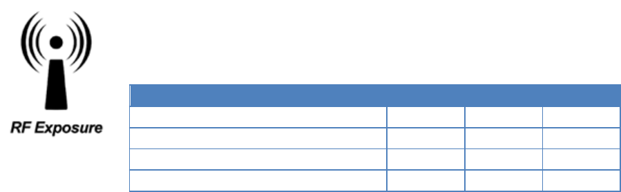
RF Exposure Compliance Requirements
The Integra-TR radio is intended for use in the Industrial Monitoring and Control and SCADA markets.
The Integra-TR unit must be professionally installed and must ensure a minimum separation distance
listed in the table below between the radiating structure and any person. An antenna mounted on a
pole or tower is the typical installation and in rare instances, a 1/2-wave whip antenna is used.
Antenna Gain
Min Safety Distance (cm @max power)
5 dBi
10 dBi
15 dBi
VHF
79.3 cm
141.0 cm
250.8 cm
UHF
68.2 cm
121.4 cm
215.8 cm
900 MHz
45.0 cm
80.1 cm
142.5 cm
It is the responsibility of the user to guarantee compliance with the FCC MPE regulations when operating this device in a way
other than described above.
Integra-TR uses a low power radio frequency transmitter. The concentrated energy from an antenna may pose a health
hazard. People should not be in front of the antenna when the transmitter is operating.
The installer of this equipment must ensure the antenna is located or pointed such that it does not emit an RF field in
excess of Health Canada limits for the general population. Recommended safety guidelines for the human exposure to radio
frequency electromagnetic energy are contained in the Canadian Safety Code 6 (available from Health Canada) and the
Federal Communications Commission (FCC) Bulletin 65.
Any changes or modifications not expressly approved by the party responsible for compliance (in the country where used)
could void the user's authority to operate the equipment.

1 TABLE OF CONTENTS
1.1 Figures ........................................................................................................................................................................ 6
1.2 Tables .......................................................................................................................................................................... 7
2 PRODUCT OVERVIEW .................................................................................................................................................... 8
2.1 Scope of Manual ......................................................................................................................................................... 8
2.2 General Description ................................................................................................................................................... 8
2.2.1 Characteristics ...................................................................................................................................................... 8
2.3 Part Number Breakdown .......................................................................................................................................... 9
2.3.1 Transceiver Identification .................................................................................................................................... 9
2.3.2 Accessories and Options ...................................................................................................................................... 9
2.3.3 Factory Mutual NI Kit ....................................................................................................................................... 10
2.3.4 Configuration ..................................................................................................................................................... 12
2.4 Factory Repair ......................................................................................................................................................... 12
2.5 Physical Description................................................................................................................................................. 12
2.6 Diagnostics ................................................................................................................................................................ 12
2.7 Firmware Updates ................................................................................................................................................... 13
2.8 Network Application ................................................................................................................................................ 13
2.8.1 RF Path and Communications Range ................................................................................................................ 13
2.8.2 Basic Connections .............................................................................................................................................. 13
2.8.3 Common Characteristics .................................................................................................................................... 14
2.8.4 Point-to-Point System ........................................................................................................................................ 14
2.8.5 Point-to-Multipoint System................................................................................................................................ 14
2.8.6 Extending a Landline (Tail Circuit) ................................................................................................................... 15
2.9 Specifications ............................................................................................................................................................ 17
3 FEATURES AND OPERATION ..................................................................................................................................... 20
3.1 Overview ................................................................................................................................................................... 20
3.2 Front Panel ............................................................................................................................................................... 20
3.2.1 Antenna Connector ............................................................................................................................................ 20
3.2.2 Connection to DTE ............................................................................................................................................ 20
3.2.3 LED Indicators ................................................................................................................................................... 20
3.2.4 COM Port ........................................................................................................................................................... 21
3.2.5 Setup Port ........................................................................................................................................................... 22
3.3 Rear Panel ................................................................................................................................................................ 23
3.3.1 Heat Sink............................................................................................................................................................ 23
3.3.2 Power ................................................................................................................................................................. 23
3.3.3 Power – I/O Connector ...................................................................................................................................... 23
3.4 Integra-TR Field Programming Software ............................................................................................................. 24
3.4.1 Introduction ........................................................................................................................................................ 24
3.4.2 Setup Modem/Radio Parameters ........................................................................................................................ 25
3.4.3 Version Request ................................................................................................................................................. 38
3.4.4 List Information ................................................................................................................................................. 39
3.4.5 Apply Integra Reset ........................................................................................................................................... 39
3.4.6 Program Comment/ID ........................................................................................................................................ 39
3.4.7 Program Parameters ........................................................................................................................................... 40
3.4.8 Read Parameters................................................................................................................................................. 41
3.4.9 Copy Parameters ................................................................................................................................................ 41

3.4.10 COM Port Settings ............................................................................................................................................. 41
3.4.11 Swap COM Ports ............................................................................................................................................... 44
3.4.12 Port Statistics ..................................................................................................................................................... 45
3.4.13 Offline Link Test................................................................................................................................................ 46
3.4.14 Offline Diagnostics ............................................................................................................................................ 48
3.4.15 Online Diagnostics ............................................................................................................................................. 50
3.4.16 Diagnostic IDs and Alarms ................................................................................................................................ 52
3.4.17 User Test ............................................................................................................................................................ 54
3.4.18 Packet Test ......................................................................................................................................................... 56
3.4.19 Array Test .......................................................................................................................................................... 58
3.4.20 Ping Test ............................................................................................................................................................ 60
3.4.21 ASCII / Hex Terminal ........................................................................................................................................ 63
3.4.22 Program Code Menu .......................................................................................................................................... 64
3.5 Integra-TR Help Files .............................................................................................................................................. 65
3.6 Optimizing Your System ......................................................................................................................................... 65
4 CONFIGURABLE PARAMETERS ................................................................................................................................ 67
4.1 Parameter Overview ................................................................................................................................................ 67
5 DEFINITIONS ................................................................................................................................................................. 69
1.1 FIGURES
Figure 1- FM Approved External Connections ......................................................................................................................... 10
Figure 2- Installation Dimensions ............................................................................................................................................. 11
Figure 3 - Basic Required Connections .................................................................................................................................... 13
Figure 4 - Point-to-Point System .............................................................................................................................................. 14
Figure 5 - Point-to-Multipoint System (simplex or half-duplex) .............................................................................................. 14
Figure 6 - Point-to-Multipoint System (full-duplex)................................................................................................................. 15
Figure 7 - Point-to-Multipoint System (full-duplex repeater) ................................................................................................... 15
Figure 8 - Landline (Tail Circuit) ............................................................................................................................................. 15
Figure 9 - DCE Crossover Cable for RTS-CTS Mode .............................................................................................................. 16
Figure 10 - DCE Crossover Cable for DOX Mode ................................................................................................................... 16
Figure 11 - COM and Setup Port Connectors Pin Locations .................................................................................................... 22
Figure 12 - 3-wire Interface ...................................................................................................................................................... 22
Figure 13 - Integra-TR Rear Panel ............................................................................................................................................ 23
Figure 14 - I/O Connector ......................................................................................................................................................... 23
Figure 15 - Integra-TR Field Programming Software Startup Screen ...................................................................................... 24
Figure 16 - Setup Modem/Radio Parameters Screen ................................................................................................................ 25
Figure 17 - Suspend Mode Timing ........................................................................................................................................... 29
Figure 18 - COM/Analog Setup Parameters Screen ................................................................................................................. 29
Figure 19 - Integra-TR Control Signal Timing ......................................................................................................................... 30
Figure 20 - Digital I/O Circuit Diagram ................................................................................................................................... 32
Figure 21 - Integra Power I/O Cable ......................................................................................................................................... 32
Figure 22 - Integra Field Programming Software Digital I/O Screens ..................................................................................... 34
Figure 23 - Radio Setup Parameters Screen .............................................................................................................................. 35
Figure 24 - Frequencies Tab ..................................................................................................................................................... 37
Figure 25 - Version Request Screen ......................................................................................................................................... 39
Figure 26 - List Request Screen ................................................................................................................................................ 39
Figure 27 - Reset Screen ........................................................................................................................................................... 39
Figure 28 - Program Comment/ID Screen ................................................................................................................................ 40
Figure 29 - Program Parameters ............................................................................................................................................... 40
Figure 30 - Port Settings Screen ............................................................................................................................................... 41

Figure 31 - Port Statistics Screen .............................................................................................................................................. 45
Figure 32 - Offline Link Test Screen ........................................................................................................................................ 46
Figure 33 - Offline Diagnostics Screen ..................................................................................................................................... 48
Figure 34 - Online Diagnostics ................................................................................................................................................. 51
Figure 35 - Diagnostic IDs and Alarms Screen......................................................................................................................... 52
Figure 36 - User Test Screen .................................................................................................................................................... 54
Figure 37 - Packet Test Screen ................................................................................................................................................. 56
Figure 38 - Array Test Screen ................................................................................................................................................... 58
Figure 39 - Ping Test Screen ..................................................................................................................................................... 60
Figure 40 - ASCII Terminal Screen .......................................................................................................................................... 63
Figure 41 - Select Firmware File Window (for reference only) ................................................................................................ 64
Figure 42 - Integra-TR Online Help Introductory Screen ......................................................................................................... 65
1.2 TABLES
Table 1- Integra-TR Part Number Breakdown ............................................................................................................................ 9
Table 2 - Accessories .................................................................................................................................................................. 9
Table 3 - LEDs Color Functions*** ......................................................................................................................................... 21
Table 4 - COM Port Signals ...................................................................................................................................................... 21
Table 5 - Setup Port Signals ...................................................................................................................................................... 22
Table 6 - Diagnostics Information ............................................................................................................................................ 27
Table 7 - 4 Channel Select Mode .............................................................................................................................................. 35
Table 8 - Communications Mode .............................................................................................................................................. 43
Table 9 - Y-Cable Connections ................................................................................................................................................. 57
Table 10 - SWR / Rev Pwr Interpretation ................................................................................................................................. 66
Table 11 - Normal Factory Settings (Units) .............................................................................................................................. 67
Table 12 - Normal Factory Settings (Bases) ............................................................................................................................. 68

Integra-TR User Manual Page | 8
2 PRODUCT OVERVIEW
2.1 SCOPE OF MANUAL
This document provides the information required for the operation and preventive maintenance of the Integra-TR
integrated wireless modem. This manual is intended for system designers, installers and maintenance technicians.
2.2 GENERAL DESCRIPTION
Integra-TR is a high-speed transparent integrated wireless modem. It is FCC refarming compliant and designed specifically
to fit the needs of SCADA, telemetry and control applications. Integra-TR provides the communication links to data
equipment for installations where wired communication is impractical.
Integra-TR works with most makes and models of remote terminal units (RTU) and programmable logic controllers (PLC)
and their protocols. Configuration settings allow tailoring for a variety of applications. Integra-TR supports:
1. Point to point Master-Remote or Peer-to-Peer configurations in simplex or half-duplex modes.
2. Point to multipoint Master-Remote configuration in simplex or half-duplex modes and offers full-duplex in dual-
unit configuration. These configurations are available as I-Base products. Contact your CalAmp Representative for
details.
2.2.1 CHARACTERISTICS
Integra-TR has the following characteristics:
Selectable network speeds of 2400 and 4800 b/s for quarter channel units, 4800 and 9600 b/s for half channel
units as well as 4800, 9600 and 19200 b/s for full channel units
Backward compatible with the Integra-T for bit rate of 4800 and 9600 b/s (full channel units only)
One COM port for connection to DTE. Speed of 1200 - 19200 baud
One Setup port for configuration and diagnostics (speed fixed to 9600 baud, 8 bit, no parity, 1 stop bit)
Built-in 5-watt transceiver (adjustable 1-5 watts), operating in the VHF, UHF or 900 MHz communications bands.
Half-duplex or simplex operation
Fully transparent operation with error-free data delivery
Allows transmission of “break” characters
DOX (Data Operated Transmit) or RTS mode
Stations may be set as “master” or “remote” to prevent remote stations from hearing each other in a simplex RF
configuration
Full local and remote diagnostics
Two configurable I/O lines programmable as either 8-bit analog inputs or digital outputs
“12 VDC, negative ground” device
CWID provides the ability to program the unit to periodically identify itself on the air by sending the FCC Station ID
in Morse code
Disable Tx w/Carrier Present configures the unit to prevent transmission when the radio channel is busy
Low power consumption modes: “sleep” and “suspend” modes (< 20 mA)
Multi-channel capability under system PLC control provides advanced network monitoring

Integra-TR User Manual Page | 9
2.3 PART NUMBER BREAKDOWN
The following table provides a breakdown of the Integra-TR part number.
Table 1- Integra-TR Part Number Breakdown
242-40W8-XYZ*
W
X
Y
Z (UHF Units)
1 VHF
0 406.1-422 MHz
0 6.25 kHz
0 406.1-422 MHz,
or Dual Band
4 UHF
1 380-400 MHz
1 12.5 kHz
1 414-430 MHz
9 900 MHz
2 403-419 MHz
3 25 kHz
3 419-435 MHz (UHF), 406.1-440 MHz (UHF Dual Band)
5 Dual Band
12.5 & 25 kHz
4 132-150 MHz (VHF), 435-451 MHz (UHF)
5 450-470 MHz (UHF), 440-476 MHz (UHF Dual Band),
928-960 MHz (900 MHz)
6 150-174 MHz (VHF), 464-480 MHz (UHF)
7 480-496 MHz
8 496-512 MHz
*An F should follow any part number to designate an Integra-TR with the cooling fan option.
2.3.1 TRANSCEIVER IDENTIFICATION
The transceiver identification is a random, unique serial number (SN) printed on the box label and model label
on the side of the Integra-TR unit.
2.3.2 ACCESSORIES AND OPTIONS
Table 2 - Accessories
Accessory
DRL Part Number
Integra-TR Field Programming Kit includes software, technical manual on CD ROM with
programming cable (DRL part number 697-4008-408)
250-4008-001
SMA to Type N-Male Adapter Cable
697-5000-101
Integra-TR Start-Up Disc includes Field Programming Software, Manual and Quick Start
Guide
002-4008-100
*Cooling fan - factory option (For extended duty-cycle transmit applications)
Catalog number plus “F” suffix.
Power cable
697-4008-001
Factory Mutual NI Kit
023-1000-200
Switching Power Converter (SPC)
250-0300-133
Demo Power Kit
250-0300-175
Data Interface Kit
250-0045-103
Data Diagnostic Kit
250-0005-105
Integra-TR User Manual Page | 10
Integra-TR DIN-rail Mounting Kit
250-5800-408
*Full-duplex base station
Contact Technical Service
VHF Antenna Kit
Contact Sales Representative
*For extended-transmit applications, the “TX Time out” timer must be turned off (set to “disable”) via the Field Pro-
gramming Software.
For information on accessories and options, contact your sales representative. In the United States phone 1-800-9927774
or 1-507-833-8819, for International inquiries phone 507-833-8819.
2.3.3 FACTORY MUTUAL NI KIT
The Integra-TR with the Factory Mutual NI Kit (DRL part number 023-1000-200) is approved as non-incendive for Class I,
Groups ABCD, Division 2, hazardous locations by Factory Mutual Research Corporation. This option includes approval for
International Electrotechnical Commission (IEC) Class I, Zone 2.
Approved models are labeled with this rating. Only units with the Factory Mutual approved label carry the nonincendive
rating. Installation, service, and repair of the FM approved units must be in accordance with the instructions found in this
manual and the National Electrical Code (ANSI-NFPA 70) Division 2: Hazardous (classified) Location Incendive Wiring
Techniques. Mount the unit in an enclosure or assembly. Route all interconnecting cables (DC power and coaxial) through
conduit as specified in the National Electrical Code document referenced above. For further guidance on installation, see
ANSI\ISA-RPI2.6: Installation of Intrinsically Safe Systems for Hazardous (Classified) locations.
Figure 1- FM Approved External Connections
Integra-TR User Manual Page | 11
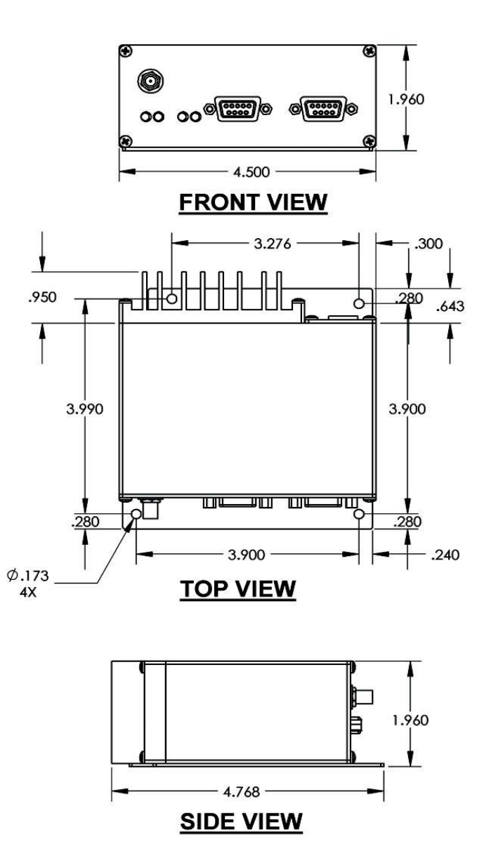
Figure 2- Installation Dimensions

Integra-TR User Manual Page | 12
2.3.4 CONFIGURATION
Operating characteristics of the Integra-TR are configured by means of Integra-TR's Field Programming Software. The Field
Programming Software is Windows based and requires a Windows® 98 or later operating system running the Integra-TR
Field Programming Software for both configuration and adjustment.
2.4 FACTORY REPAIR
CalAmp guarantees that every Integra-TR module will be free from physical defects in material and workmanship for two (2)
years from the date of purchase when used within the limits set forth in the Specifications section of this manual. The
manufacturer's warranty statement for this product is available in Appendix 1. If the product proves defective during this
warranty period, call CalAmp Customer Service to obtain a Return Material Authorization (RMA). BE SURE TO HAVE THE
EQUIPMENT MODEL AND SERIAL NUMBER, AND BILLING AND SHIPPING ADDRESSES ON HAND WHEN CALLING. You may
also request an RMA online at www.calamp.com.
When returning a product, mark the RMA clearly on the outside of the package. Include a complete description of the
problem and the name and telephone number of a contact person. RETURN REQUESTS WILL NOT BE PROCESSED WITHOUT
THIS INFORMATION.
For units in warranty, customers are responsible for shipping charges to CalAmp. For units returned out of warranty,
customers are responsible for all shipping charges. Return shipping instructions are the responsibility of the customer.
CalAmp reserves the right to update its products, software, or documentation without obligation to notify any individual or
entity. Please direct all inquiries to:
CalAmp, 299 Johnson Ave., Ste 110, Waseca, MN 56093 Telephone 507.833.8819 or Toll Free 800.992.7774
2.5 PHYSICAL DESCRIPTION
Integra-TR consists of a logic PCB (which includes modem circuitry) and a radio module. Each logic PCB and radio module
are matched together and characterized in the factory to optimize performance as an intelligent unit. The two boards then
slide into the rails of an extruded aluminum case.
DTE connection is made via a front panel connector. Power is applied through a rear panel 4-pin connector which includes
two programmable analog connections usable as inputs or outputs.
The unit is not hermetically sealed and should be mounted in a suitable enclosure when dust and/or a corrosive
atmosphere are anticipated. Physically, there are no external switches or adjustments. All operating parameters are set
using the Field Programming Software.
2.6 DIAGNOSTICS
Integra-TR has sophisticated built-in diagnostics that may be transmitted automatically without interfering with normal
network operation. In addition, commands to generate test transmissions, etc., may be issued either locally or remotely.
Diagnostic information takes one of two forms:
Online Diagnostics - Information is automatically sent by each unit at the beginning of every data transmission.
Integra-TR User Manual Page | 13
Offline Diagnostics - Information is sent by a specific unit in response to an inquiry made locally or from another station.
2.7 FIRMWARE UPDATES
The Integra-TR firmware resides in flash EPROM and is designed to allow field updates.
Updates are done using a PC connected to the Integra-TR but do not require opening the unit. Updates will be coordinated
by DRL’s Technical Service.
2.8 NETWORK APPLICATION
Integra-TR is suited to a variety of network applications. Its primary design goal was to satisfy the needs of SCADA systems
using RTUs or PLCs in either point-to-point or point-to-multipoint service.
This section gives an overview of some common configurations. Selection of “master” or “remote” as well as data delivery
conditions is done using the Integra-TR Field Programming Software.
2.8.1 RF PATH AND COMMUNICATIONS RANGE
Integra-TR is designed for use over distances up to 30 miles + (50 km) depending on terrain and antenna system. To assure
reliable communications, the RF (radio frequency) path between stations should be studied by a competent professional
who can determine what antennas are required and whether or not a repeater is needed. Your CalAmp Sales
Representative can assist you.
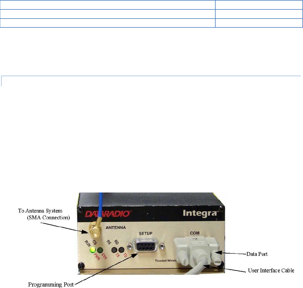
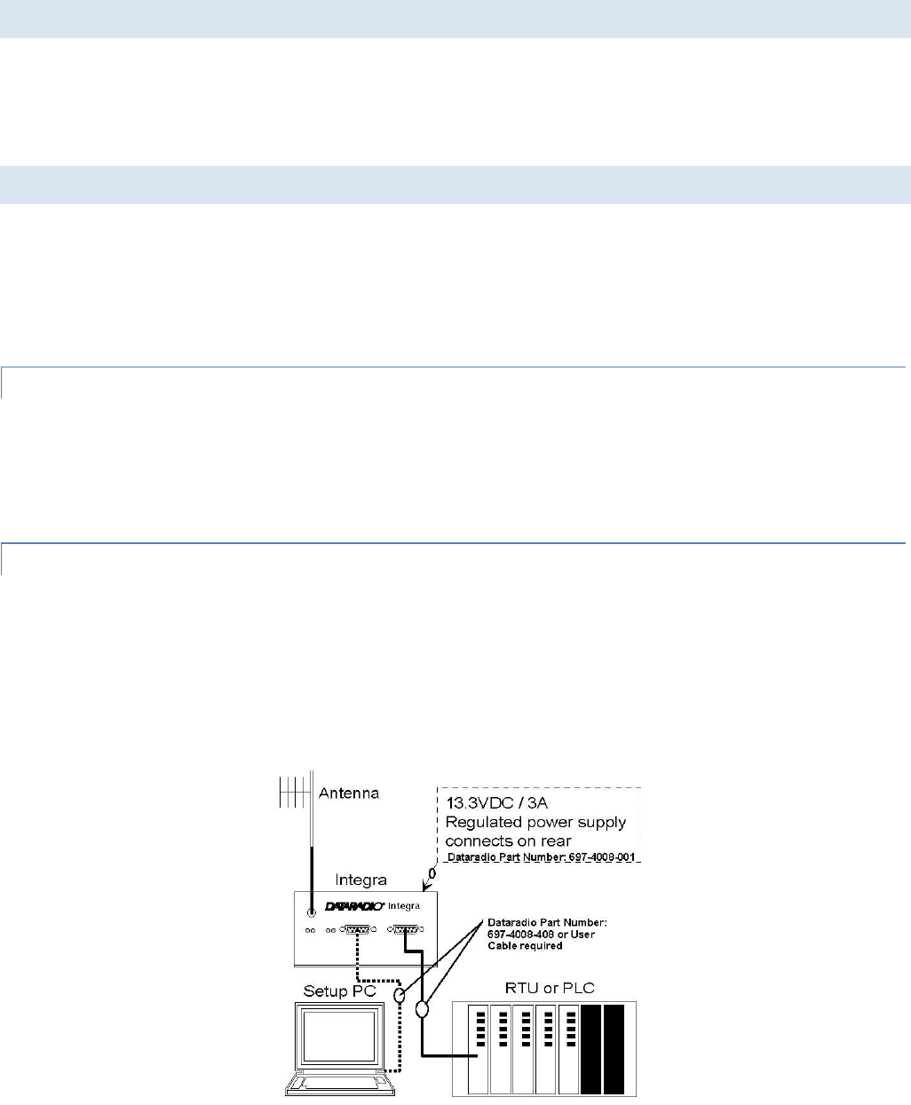
2.8.2 BASIC CONNECTIONS
The connections required are shown in Figure 3.
While an RTU or PLC is shown in the diagram, master stations often use a PC running an application designed to
communicate with remote RTUs or PLCs. The Setup PC is used for both configuration and local and remote diagnostics. It
may be left connected at all times but is not required for normal operation once the unit has been configured.
Figure 3 - Basic Required Connections
Integra-TR User Manual Page | 14
2.8.3 COMMON CHARACTERISTICS
The networks described in this section share common characteristics:
1. The DTE (data terminal equipment) network speed (1200, 2400, 4800, 9600 and 19,200 b/s) must be the same for all
stations in a network.
2. Transmission of online diagnostics may be enabled or disabled at any station or stations without affecting their ability
to communicate with other stations.
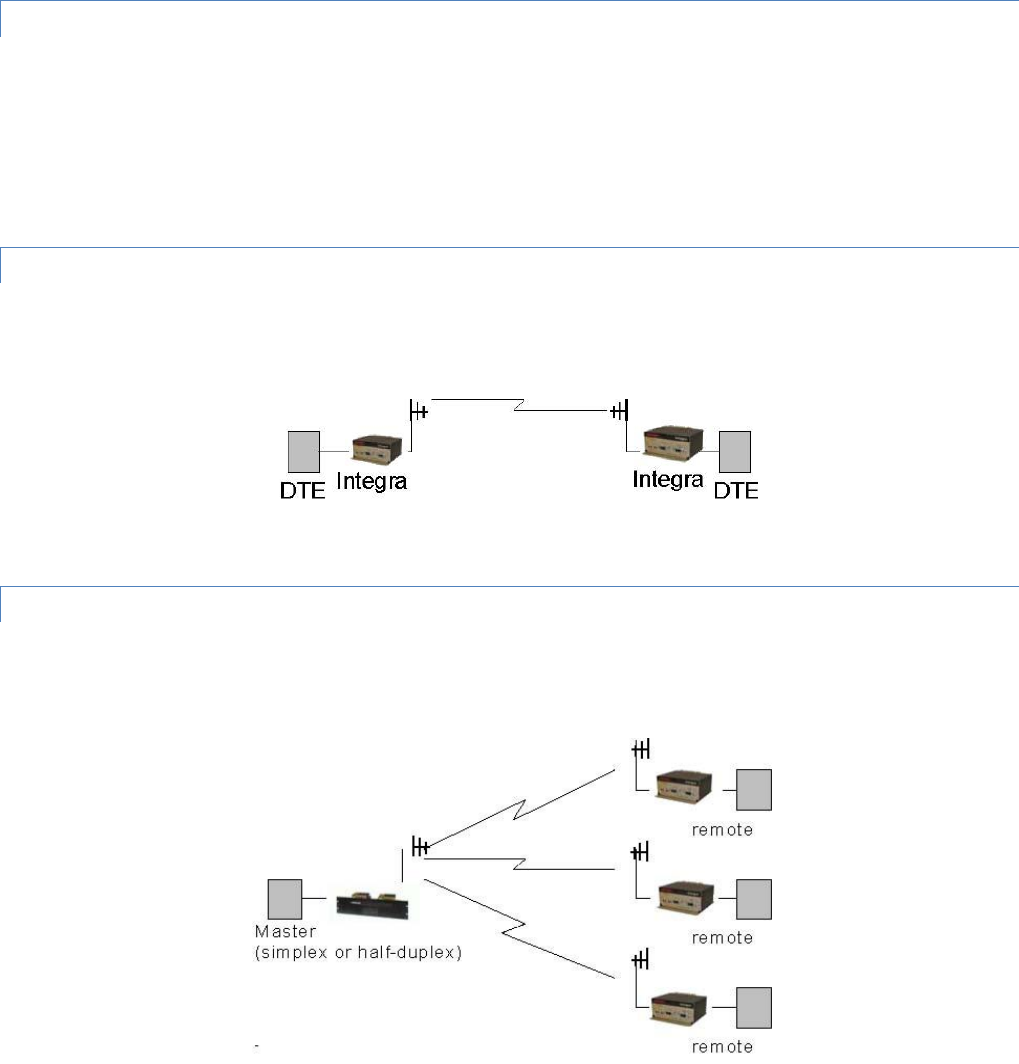
2.8.4 POINT-TO-POINT SYSTEM
Simple point-to-point connection is shown in Figure 4.
Figure 4 - Point-to-Point System
In this system, the user's equipment (DTE) may be set up in either a peer-to-peer or a Master-Remote configuration.
2.8.5 POINT-TO-MULTIPOINT SYSTEM
Basic point-to-multipoint systems are shown in Figure 5.
Figure 5 - Point-to-Multipoint System (simplex or half-duplex)
If a half-duplex radio network is used (i.e. two frequencies with the master station transmitting and receiving on the reverse
pair from the remotes), the master station can be either full duplex or half-duplex.
If a simplex radio network is used (i.e. a single frequency for all stations), we recommend that the master Integra-TR be set
to “master”, the remotes to “remote” and all units to “selective” data delivery. This will prevent remote stations from
hearing each other's responses. For full duplex configuration, set the receiving unit Rx/Tx Mode to Rx Only (using the Field
Programming Software). Set the transmitting unit mode to Tx Only.
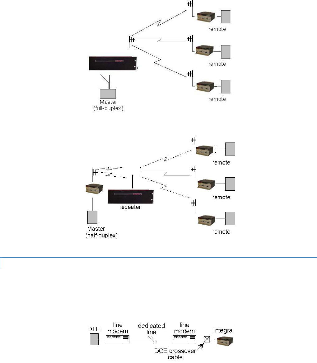
Integra-TR User Manual Page | 15
Figure 6 - Point-to-Multipoint System (full-duplex)
Figure 7 - Point-to-Multipoint System (full-duplex repeater)
2.8.6 EXTENDING A LANDLINE (TAIL CIRCUIT)
Integra-TR may be used to extend a landline circuit (giving access to difficult locations, etc.). This type of connection is
called a “tail circuit” and is shown in Figure 8. The tail circuit assembly may be used in any of the network types described in
the preceding sections.
Figure 8 - Landline (Tail Circuit)
Note: The line modems should be full-duplex units.

Integra-TR User Manual Page | 17
2.9 SPECIFICATIONS
These specifications are subject to change without notice. RF specifications are measured per TIA/EIA-603 with a
psophometric baseband filter.
General
VHF
UHF
900 MHz
Frequency
132-174 MHz
380-400 MHz*, 403-512 MHz,
406.1-476 MHz Dual Band
928-960 MHz
Channels
Multi-channel capability under system PLC control
Channel Bandwidth
6.25, 12.5 or 25 kHz models
Operating Temperature
-30° to + 60° C
Supply Voltage
10 - 16 VDC maximum (nominal 13.3) Fuse protected against reverse voltage
(internal surface mount 3A fuse: not field replaceable)
RX Current Drain at 13.3 VDC
<220 mA (with a terminal connected to Integra-TR COM port)
TX Current Drain at 13.3 VDC
<2.6 A
Power Saving Mode Current Drain
<20 mA
Cold Start1
4 sec (typical)
Warm Start Rx2
45 to 60 ms (depending on radio model and temperature)
Warm Start Tx3
55 to 70 ms (depending on radio model and temperature)
Tx Turn On Time4
15 ms (typical)
RX/TX Bandwidth (without tuning)
18 MHz (132-150)
24 MHz (150-174)
16 MHz except
20 MHz (380-400, 450-470)
34 MHz (406.1-440 Dual)
36 MHz (440-476 Dual)
32 MHz
*380 to 400 MHz frequency band is not FCC or IC type approved
+Includes 102 cm power cable
Receiver
VHF
UHF
900 MHz
Sensitivity
0.35 µV for 12 dB SINAD
Selectivity (25 kHz)
>70 dB minimum
>65 dB Minimum UHF Dual Band
> 65 dB minimum
Selectivity (12.5 kHz)
>60 dB minimum
>55 dB Minimum UHF Dual Band
>60 dB minimum
Intermodulation
>70 dB minimum
> 70 dB minimum
Spurious Rejection
>70 dB minimum
>70 dB minimum
FM Hum and Noise
<-45 dB max (25 kHz)
<-40 dB max (25 kHz)
Conducted Spurious
< -57 dBm

Integra-TR User Manual Page | 18
1 Cold Start: Time from DC power applied until unit is fully ready to receive or transmit data
2 Warm Start Rx: In power saving modes (sleep or suspend), wake-up time for full receiver recovery
3 Warm Start Tx: In power saving modes (sleep or suspend), wake-up time for full transceiver operation
4 Tx Turn On Time: Typical Rx to Tx switching time for stable transmission
Transmitter
VHF
UHF
900 MHz
RF Power Output
1 to 5 Watts, software adjustable
Spurious and Harmonics
<-57 dBc (-20 dBm)
Frequency Tolerance
1.5 PPM
FM Hum and Noise
<-45 dB (25 kHz)
<-40 dB (25 kHz)
Tx Duty Cycle
50%, max. Tx time 30 seconds, extended Tx time with the cooling fan option
Modem / Logic
Operation
Simplex / half duplex
Data Bit Rates
25 kHz channel: 4800 b/s, 9600 b/s, 19200 b/s
12.5 kHz channel: 4800 b/s, 9600 b/s
6.25 kHz channel: 2400 b/s, 4800 b/s
Modulation Type
DRCMSK (Differential Raise-Cosine Minimum Shift Keying)
RTS/CTS Delay (RTS mode)
4 ms
Addressing
10 bit station address, 1 bit station type (master / remote)
Bit Error Rate (BER)
12.5 kHz @ 9.6 kbps: -104 dBm, 1x10⁻⁶ @ 1.4 µV
25 kHz @ 4.8 or 9.6 kbps: -107 dBm, 1x10⁻⁶ @ 1.0 µV
25 kHz @ 19.2 kbps: -100 dBm, 1x10⁻⁶ @ 2.3 µV
COM Port
Interface
EIA RS-232C
Data Rate
1200 - 19200 b/s
Protocol
Transparent, 7 or 8 data bits, 1 or 2 stop bits, even, odd or no parity
Transmit Control
RTS or DOX (data operated transmit)
Setup / Diag Port
Data Format
Proprietary binary for setup, ASCII for diagnostics
Data Rate
9600 b/s, 8 bit, no parity, 1 stop bit
Analog Inputs
Interface
Two inputs, 0-10 VDC, 8 bits. May be read only via Offline Diagnostics. Absolute
maximum input voltage < 20 Vdc. Inputs are reverse-voltage protected.
Digital Outputs

Integra-TR User Manual Page | 19
Interface
Two outputs, requires external pull-up to 2 to 10 Vdc. Set via Offline Diagnostics
Display
4 Bi-color status LEDs
RUN/PWR/ CS/SYN, RX/TX, RD/TD
Connectors
RF
SMA Female
COM
DE-9F
SETUP/DIAG
DE-9F
Power - I/O
Snap & Lock 4-Pin DC Power Jack
Diagnostics
Online
Short ID, temperature, B+ voltage, local RSSI, remote RSSI, fwd and rev power, Rx
Quality
Offline
As for Online plus: Demodulated Signal Voltage, Analog Input Levels, Digital
Outputs
Certifications
FCC (6.25 kHz)
FCC (12.5 & 25 kHz)
IC (DOC)
VHF
NP4MCUA5Q
6K00F1D
EOTMCUA5R
9K30F1D, 15K3F1D
773195562A
9K30F1D, 15K3F1D
UHF
NP4MCUB5Q
6K00F1D
EOTMCUB5R
9K30F1D, 15K3F1D
773195561A
9K30F1D, 15K3F1D
UHF Dual Band
NP44048350
9K30F1D, 15K3F1D
773B-4048350
9K30F1D, 15K3F1D
900 MHz
NA
EOTMCUC5R
9K30F1D, 15K3F1D
7731955611A
9K30F1D, 15K3F1D
Integra-TR User Manual Page | 20
3 FEATURES AND OPERATION
3.1 OVERVIEW
This chapter describes the connections, indicators, and operating characteristics of the Integra-TR. This chapter is intended
for system application and installation personnel.
3.2 FRONT PANEL
The various front panel elements are described in the following sections.
3.2.1 ANTENNA CONNECTOR
Antenna connector is a female 50-ohm SMA- type. Units operated with a “rubber duck” antenna connected directly to the
antenna connector may exhibit unusual operating characteristics and high levels of reverse power.
3.2.2 CONNECTION TO DTE
Integra-TR is configured as DCE. Most DTE devices should be connected using a nine-conductor pin-to-pin “straight” cable
(CalAmp part number 697-4008-408). Some RTUs or PLCs may require a special cable to route the signals correctly. See the
documentation for your data equipment for further information. Contact CalAmp for DTE interface information or review
CalAmp’s Technical Services Application Notes available on our website at www.calamp.com.
3.2.3 LED INDICATORS
Integra-TR has four two-color LED indicators. Their functions are shown in Table 3.

Integra-TR User Manual Page | 21
Table 3 - LEDs Color Functions***
RUN/PWR
Green
Normal operation
Flash Yellow and Green
Setup mode or loading new application or
new bootloader
Flash Red
Firmware error*
Red
CPU or PROM failure*
CS/SYN
Off
No RF RX carrier
Green
Receive carrier present
Red
(Reserved)
RX/TX
Off
No RF RX carrier
Green
Receiving network data
Yellow
Synthesizer unlocked
Red
Transmitter is on
RD/TD
Off
Idle
Green
RX data outgoing from RS-232 port
Red
TX data incoming at RS-232 port**
* Contact Technical Support
**or buffered in CSMA mode
***LED indicators may be different during startup
3.2.4 COM PORT
DTE baud rates from 1200 to 19200 are supported. Integra-TR's are factory set (default) for 2400 b/s (6.25 kHz) or 9600 b/s
(12.5 & 25 kHz), 8 bits, no parity, and 1 stop bit. Unless required by your operating protocol, we advise restricting port
speed to be equal to or less than the RF network speed.
Table 4 - COM Port Signals
Pin
Name
Function
1
DCD
Output: Always asserted or asserted when receive RF carrier present (selectable via Field
Programming Software)
2
RXD
Output: Data from Integra-TR to DTE
3
TXD
Input: Data from DTE to Integra-TR
4
DTR
Input: Ignored
5
GND
Signal and chassis ground
6
DSR
Output: always positive
7
RTS
Input: Used as a “begin transmission” signal in RTS mode
8
CTS
Output: Used for handshaking in RTS mode and used for flow control in DOX mode RTS mode: RTS
Integra-TR User Manual Page | 22
to CTS delay in 4 ms DOX mode: CTS always asserted except when data overflow is detected
9
RI
Not internally connected, reserved
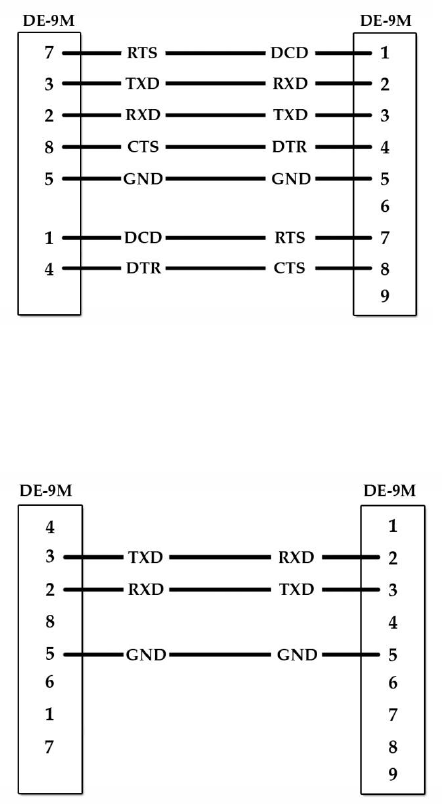
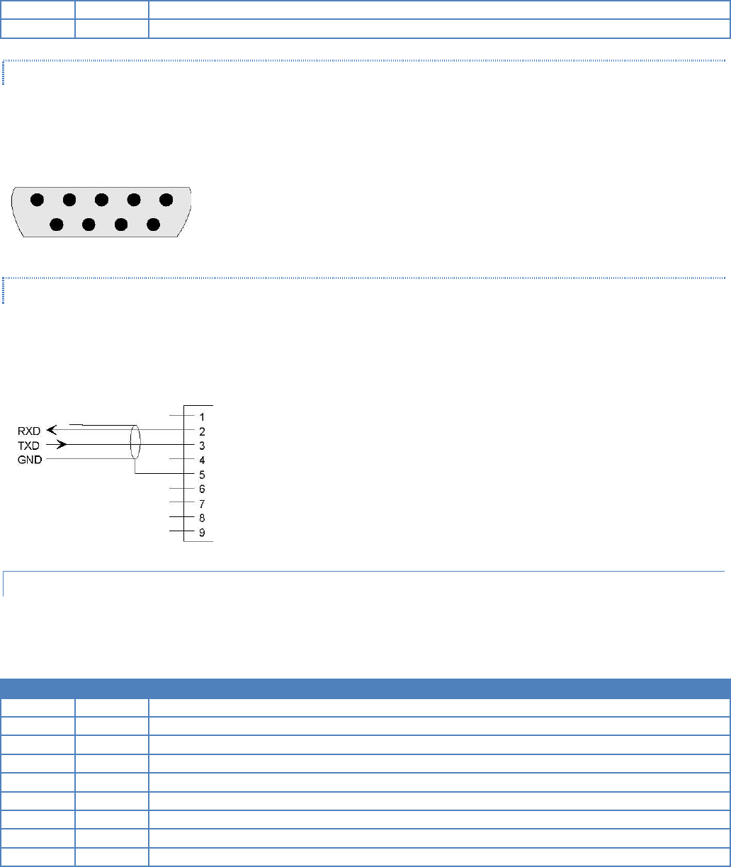
3.2.4.1 CONNECTOR PIN OUT
The DE-9F pin out is shown in Figure 11 for reference.
Figure 11 - COM and Setup Port Connectors Pin Locations
3.2.4.2 WIRE CONNECTION (DOX)
For DTE that lack RTS control, Integra-TR can operate in DOX mode (Data Operated Transmit) with only Transmit Data,
Receive Data and Ground (“3-wire interface”).
Figure 12 - 3-wire Interface
3.2.5 SETUP PORT
The Setup port uses a DE-9 female connector configured as DCE. Signals are described in Table 5.
Table 5 - Setup Port Signals
Pin
Name
Function
1
DCD
Tied directly to DTR
2
RXD
Data from Integra-TR to setup PC
3
TXD
Data from setup PC to Integra-TR
4
DTR
Tied directly to DCD
5
GND
Signal and chassis ground
6
DSR
Output: always positive (asserted)
7
RTS
Tied to CTS
8
CTS
Tied to RTS
9
RI
Not internally connected, reserved
5 4 3 2 1
9 8 7 6
Integra-TR User Manual Page | 23
The Setup port uses a proprietary communications protocol designed to work with the Integra-TR Field Programming
Software program. It is also designed to provide alpha numeric (ASCII) diagnostics information when connected to a PC
terminal emulator.
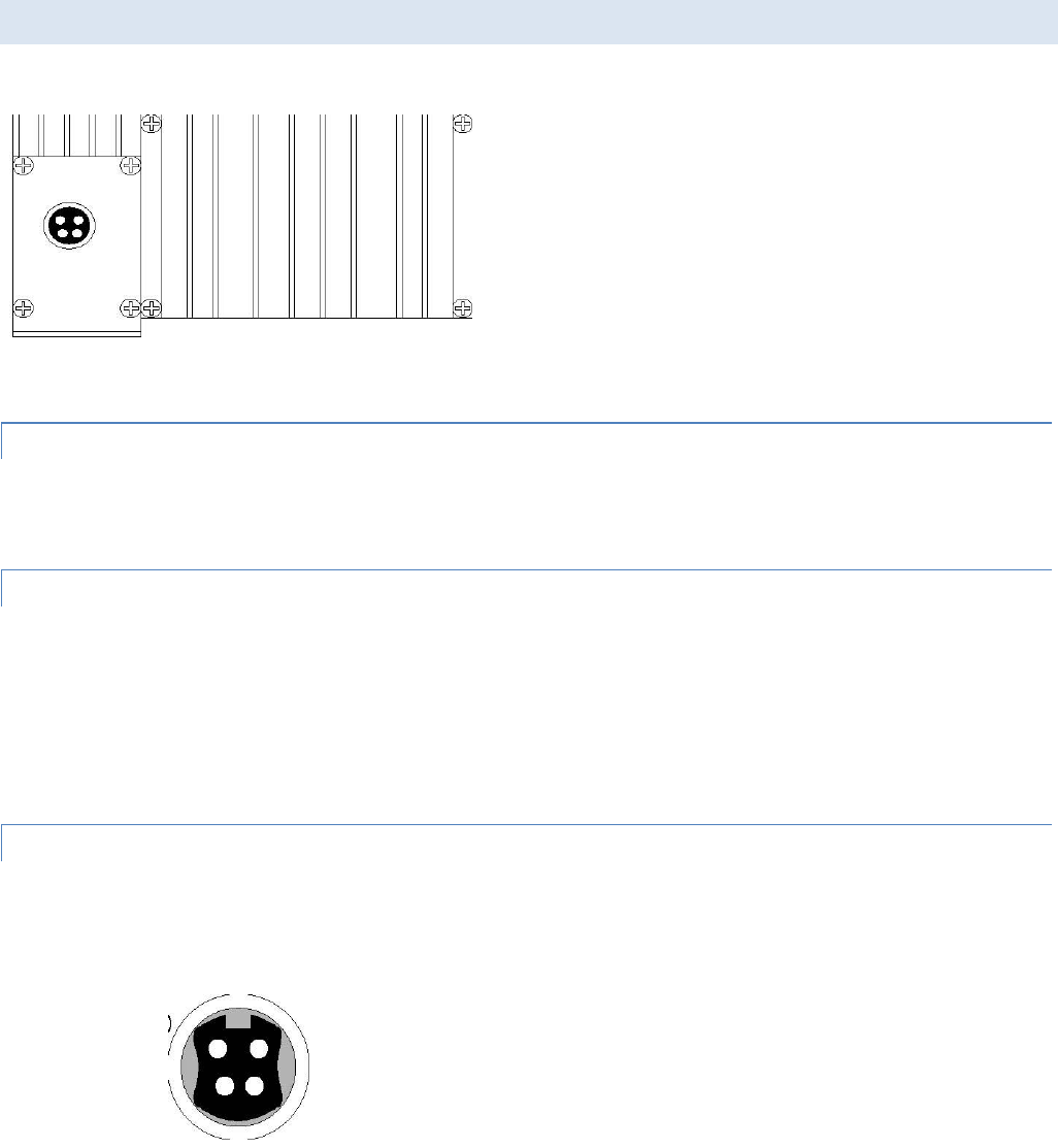
3.3 REAR PANEL
Figure 13 - Integra-TR Rear Panel
The various elements are described in the following sections.
3.3.1 HEAT SINK
The rear panel heat sink is essential for proper operation of the Integra-TR transmitter. The unit must be mounted in a
location that permits free air circulation past the heat sink. Cooling will be best if the fins are vertical.
3.3.2 POWER
The Integra-TR power requires a regulated power source of 13.3 VDC nominal (10 - 16 VDC max.) negative ground with a
3.0 A rating. An internal surface-mount 3A fuse (not field-replaceable) and a crowbar diode protect the main RF power
components from reverse polarity. Application of more than 16 VDC will damage the unit and is not covered by the
warranty.
WARNING: Do not exceed 16 VDC.
3.3.3 POWER – I/O CONNECTOR
The 4-pin power/analog connector pin out is shown in Figure 14.
Figure 14 - I/O Connector
+13.3 VDC (1)
(red)
(2) GND
(black)
(4) I/O 2 / RXTP
(white)
I/O 1 (3)
(red)
Integra-TR User Manual Page | 24
Note: The color of the power I/O cable wires are shown in parenthesis. If the I/O connections are not used the green and
white wires should be cut back and/or taped to prevent contact (power I/O cable part number 697-4008001 see Table 2).
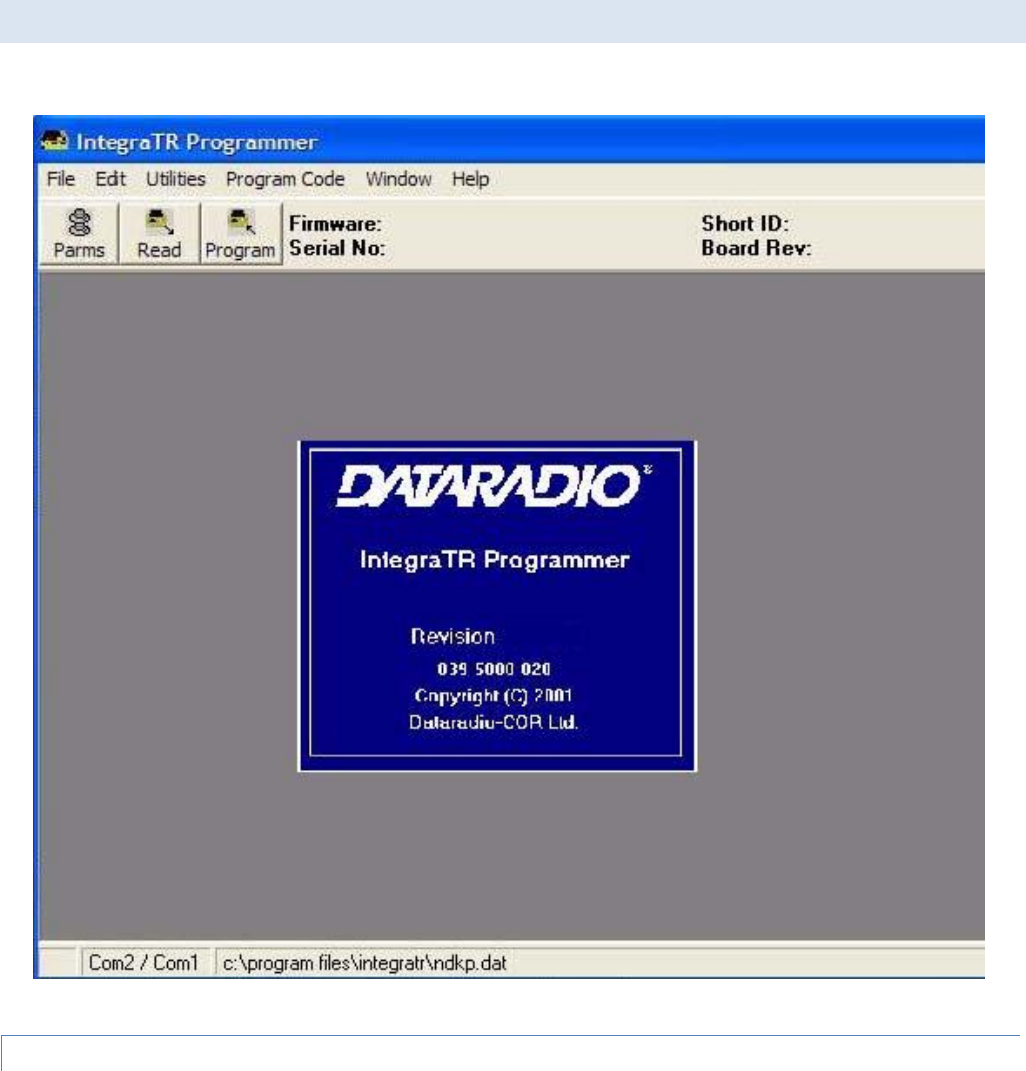
3.4 INTEGRA-TR FIELD PROGRAMMING SOFTWARE
Figure 15 - Integra-TR Field Programming Software Startup Screen
3.4.1 INTRODUCTION
Integra-TR User Manual Page | 25
The Integra-TR Field Programming Software is the programming and diagnostics software for the Integra-TR wireless
modem. The Field Programming Software allows the user to edit and program user programmable settings, interactively
tune modem and RF parameters, and monitor diagnostic data from the Integra-TR. See Figure 15 for the Integra-TR Field
Programming Software startup screen.
This manual assumes the Field Programming Software has been installed on the user’s PC with at least one operational
serial COM Port available.
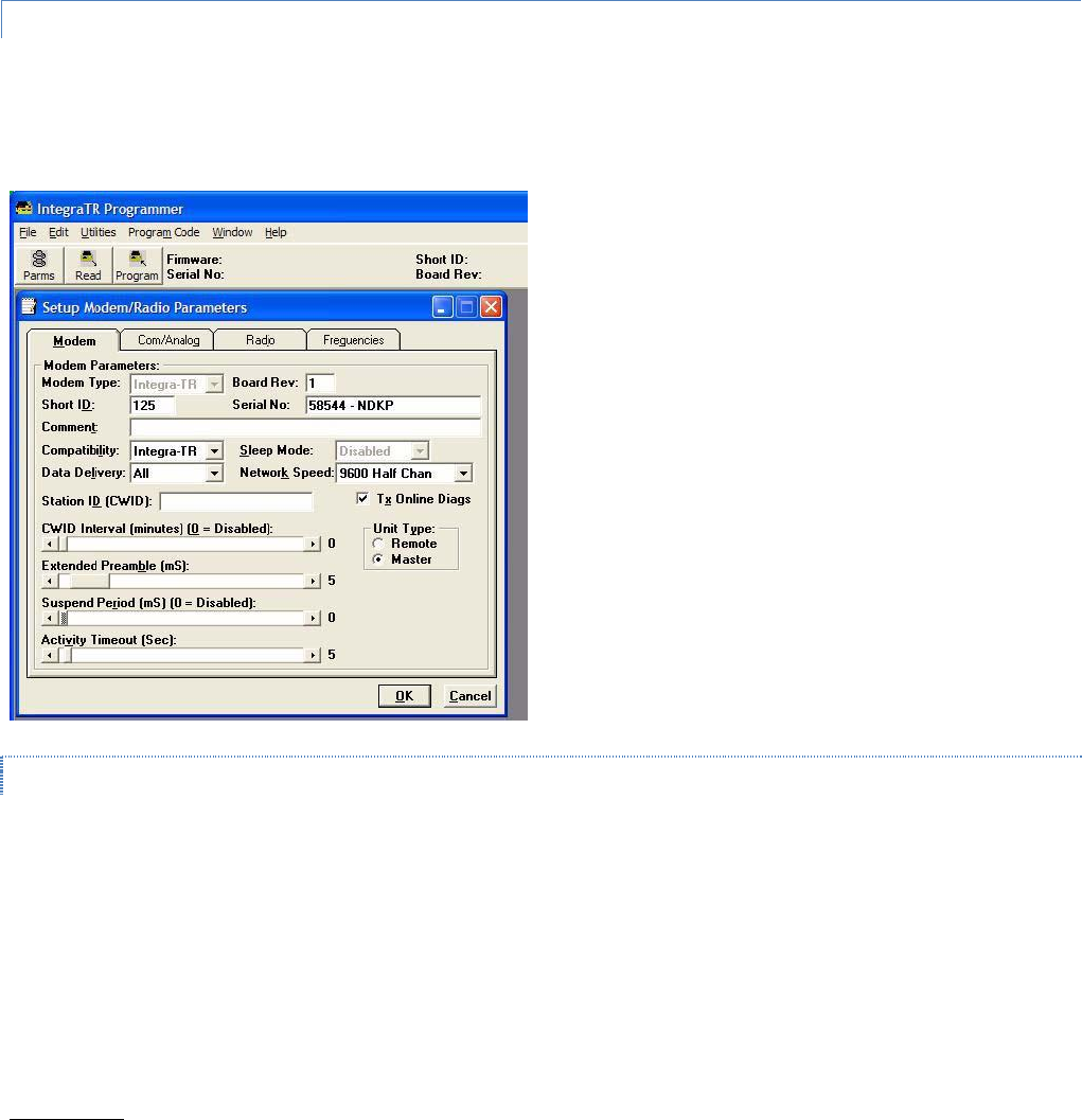
3.4.2 SETUP MODEM/RADIO PARAMETERS
The Setup Modem/Radio Parameters screen is accessed from the Edit menu pull-down or from the Parms icon when the
tool bar is visible.
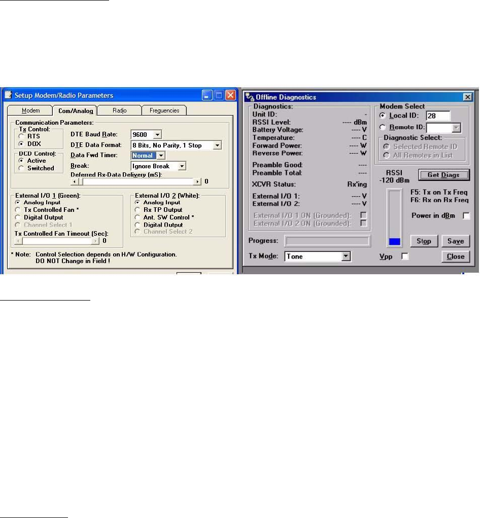
Figure 16 - Setup Modem/Radio Parameters Screen
3.4.2.1 MODEM OPERATING PARAMETERS
Setup Modem/Radio Parameters allows the user to view and edit Integra-TR’s programmable parameters. Programming
parameters can be stored in a data file with the .DAT file extension. Programmable parameters are used by the
Read/Program Parameters screen for programming into nonvolatile memory (see Figure 16). Parameter settings are
modified from four screen tabs: the Modem tab, Com/Analog tab, Radio tab and Frequencies tab. When desired
parameters in each tab window have been adjusted, select the OK button to store the parameter information into local PC
memory and exit the parameter screen. Clicking the Default Parms button sets certain parameters back to factory default
settings. Clicking Cancel exits the parameter screen without modifying any parameters currently stored in local PC memory.
Modem operating parameters include:
Modem Type

Integra-TR User Manual Page | 26
Modem type displays the type of modem (Integra-TR or Integra OIP). Modem type is a non-programmable parameter.
Board Rev
Board Rev displays the hardware revision of the modem board. Board rev is a non-programmable parameter.
Short ID
A user-defined number (from 1 to 254, 256 to 1023 - 255 is reserved) that identifies an individual unit in a network. Note:
Firmware versions 2.10 and earlier only allow short IDs of (from) 1-254.
Serial No.
Serial No. displays the serial number for the modem board. Serial No. is a non-programmable parameter.
Comment
Integra-TR Field Programming Software supplies this field for user-convenient description(s): customer name, location.
technical info...). Comments can be text up to 24 characters in length, including spaces.
Compatibility
This field selects the compatibility mode (for use with previous versions of Integras).
Integra-TR - used for networks made up of Integra-TR wireless modems.
Integra-T/TR - used for “on-air” backward compatibility with the Integra-T for bit rates of 4800 and 9600 b/s (full
channel units only).
The Integra-TR is capable of selectable network speeds of 2400 & 4800 b/s for quarter-channel units (6.25 kHz), 4800 and
9600 b/s for half-channel units (12.5 kHz) or 4800, 9600, 19200 b/s for full-channel units (25 kHz). Use the Integra-TR mode
whenever feasible.
Sleep Mode
One of the Integra-TR’s two low power modes of operation, along with and "Suspend Mode". When Sleep Mode is enabled,
the unit is in low power consumption (approximately 15 mA). In Sleep Mode, the Integra-TR cannot detect the presence of
a carrier. Only asserting RTS on the COM or Setup ports will wake the unit. It is ready to receive and decode data within 45
to 65 mS (dependent on Integra model and temperature) after wake-up.
Data Delivery
This field determines if data should be delivered to the COM port. Designating a unit as Master or Remote sets a flag in the
header identifying the Unit Type of the originating station:
All - this option causes the unit to accept (on the receive side) all data transmissions.
Selective - this option causes the unit to accept (on the receive side) data only if it originates from a unit of the
opposite Unit Type (i.e., a Master will only accept data from a Remote and a Remote will only accept data from a
Master).

Integra-TR User Manual Page | 27
Network Speed
Network Speed selects the bit rate of the RF link between units. This can be different from the COM Port baud rate. This
setting must be the same for all units in a network.
2400 b/s - selectable for quarter channel models Integra-TR only.
4800 b/s - selectable for quarter, half- and full-channel models of the Integra-TR and for full-channel models of the
Integra-T.
9600 b/s - selectable for half- and full-channel models of the Integra-TR and for full-channel models of the Integra-
T.
19200 b/s - selectable for full-channel models of Integra-TR only.
Tx Online Diags
Transmission of online diagnostics may be enabled or disabled for any unit without affecting its ability to communicate with
other units in a network. At the beginning of each data transmission from a unit, diagnostics are delivered locally to the
unit’s Setup Port regardless of the Tx Online Diags setting. Where continuous data transmissions are required from a
Master unit, diagnostics are delivered at 20 second intervals.
Online Diagnostic String Format
In ASCII output mode, the setup port will output a one line diagnostic string each time the unit receives a transmission from
another unit. No other data will be output. The string consists of a number of comma-delimited fields terminated by a
carriage return. Each field within itself is a constant length, but the fields are not all uniform in length. Field definitions are
shown in Table 6.
A typical diagnostic string (0003,+28,13.1,-093,-088,4.7,1,015,015) would be interpreted as: Remote station # 3 reports
that:
Its internal case temperature is +28°C
Supply voltage is 13.1 VDC
It is receiving a signal of -93 dBm from the master
The master is receiving a signal of -88 dBm from station 003
The forward power is 4.7 watts
The reverse power is good
15 of the last 15 data blocks were received correctly
Table 6 - Diagnostics Information
Name
Length (in bytes)
Description
Short ID
4
1 -1023 (a number from 1 to 254, 256 to 1023)
Temperature
3
Signed value
B+
4
From 6.0 to 18.8 V
Remote RSSI
4
Signal strength received by remote station in dBm
Local RSSI
4
Signal strength for this remote as received by local station in dBm
FWD Power
4
From 0 to 7 watts
Rev Power
1
0 = good 1 = poor
Rx Quality
3
Number of good data blocks received in the last 15
3
Number of total data blocks detected, maximum 15

Integra-TR User Manual Page | 28
Using an External Program for Online Diagnostics
The Setup port communicates with the field programming software using a proprietary protocol. However, if a terminal, or
PC running terminal software is connected to the Setup port, online diagnostic information will be delivered in plain ASCII
format.
Initialization
When powered on, the Integra will attempt to establish a link with the field programming software. If RTS is not exerted on
the setup port, Integra-TR will immediately switch to ASCII mode.
Unit Type
This radio button selects unit type:
Remote - Select this option to designate the unit as a Remote station
Master - Select this option to designate the unit as a Master station
Station ID (CWID)
Station ID is used to set the Station ID (CWID) or FCC Call Sign for the system. It is sent out as Morse Code at predetermined
intervals. Station ID is a combination of letters (upper-case) and numbers (0 - 9) up to 9 characters in length.
CWID Interval
CWID Interval is used to set the interval of time the unit will transmit the Station ID (CWID) or FCC Call Sign. The range is 1
to 255 minutes in 1 minute intervals, with 0 being disabled. To enable the transmissions of the Station ID (CWID) or FCC Call
Sign, a non-zero value must be set for the CWID Interval. Only one unit in a system should be programmed to transmit the
Station ID (CWID), typically the Master.
Extended Preamble
This field extends transmitted synchronization time when the unit is used in a network with repeaters. The default is 5 mS
and the range is 0 to 100 mS in 5 mS intervals. Add 10 mS for each Repeater an Integra-TR communicates through in a
network (dependent on user’s protocol).
Note: Units supplied or updated prior to November of 2001 use a default value of 0 mS for Extended Preamble. Extensive
testing has shown 5 mS to be the most robust setting. If timing is critical in your application, this value can be set back to 0
mS.
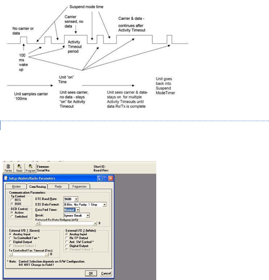
Suspend Period
Suspend Period allows the user to set the length of time the Integra-TR goes to cycled lower power mode. The range for
Suspend Period is from 50 to 12,000 mS in 50 mS intervals. Setting this range to a value of 0 disables Suspend Period.
Activity Timeout
Activity Timeout is used to set the minimum length of time the unit will remain awake in the presence of a carrier - range is
1 to 255 seconds in 1 second intervals. This field is active only if Suspend Period is enabled. A non-zero value must be set to
enable Suspend Period. The same Activity Timeout and Suspend Period values must be set for both Master and Remote
units. See Figure 17 for a Suspend Mode Timing graphic.
Integra-TR User Manual Page | 30
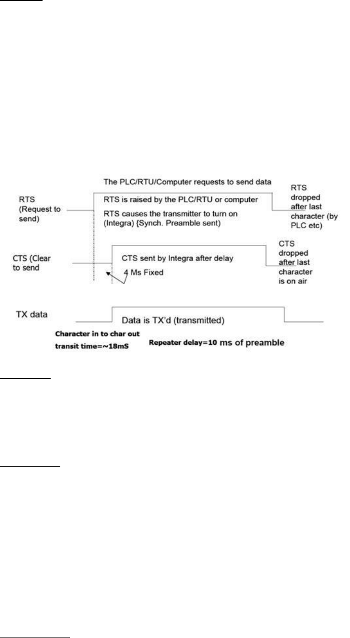
Tx Control
This radio button selects the unit’s mode at the beginning of a transmission
RTS – Request to Send
DOX – Data Operated Transmit
The Transmit Control default mode is DOX in which the unit begins a transmission as soon as data is presented to the COM
Port. The optional mode is RTS in which the unit begins transmission only when the RS-232 RTS input pin of the COM Port is
raised and continues transmitting until the RTS is dropped. Selecting RTS also activates the switched option in DCD control
(see Figure 18).
Figure 19 - Integra-TR Control Signal Timing
DCD Control
This field selects the mode of the RS-232 DCD (Data Carrier Detect)
Active - always asserted
Switched -follows the radio carrier and data sent to DTE
DTE Baud Rate
This field selects the port speed of the COM Port (independent of RF Network Speed)
1200
2400
4800
9600
19200
For best results, CalAmp recommends using the same rates for both the COM Port and RF Network Speeds. Always have RF
network speed equal to or greater than COM Port speed.
DTE Data Format

Integra-TR User Manual Page | 31
8 bits, no parity, 1 stop (default)
7 bits, no parity, 1 stop
8 bits, no parity, 2 stop
7 bits, no parity, 2 stop
8 bits, odd parity, 1 stop
7 bits, odd parity, 1 stop
8 bits, odd parity, 2 stop
7 bits, odd parity, 2 stop
8 bits, even parity, 1 stop
7 bits, even parity, 1 stop
8 bits, even parity, 2 stop
7 bits, even parity, 2 stop
Data Fwd Timer
This field selects the timing between data blocks in a transmission to accommodate some RTU’s special timing
requirements:
Normal - 15 ms option (default)
Fast - 5 ms option (do not use for baud rates below 2400 b/s)
Break
This field selects the unit’s response to break signals (protocol dependent) on the COM Port:
Ignore break - unit does not transmit or receive break signals
Transmit break - unit transmits and receives break signals
Deferred Rx-Data Delivery
This field sets the period of time the unit waits until delivering received data to the COM Port. Range is 0 to 255 ms in 1 ms
intervals (keeps delays minimum for protocols susceptible to inter-character delays).
External I/O 1 (Green)
These radio buttons select configuration of Pin 3 on the Power - I/O Connector (green wire):
Analog Input - Analog input is an option on units not equipped with the cooling fan option - can be used to monitor
an external voltage (0 to 10 volts). Monitoring is from the Offline Diagnostics screen
Tx Controlled Fan - Selecting this option will cause the unit to turn the fan ON at the start of a transmission and
OFF after a predetermined timeout (TX Controlled Fan Timeout) at the completion of a transmission. The length of
time the fan is on is the length of the transmission plus the timeout time. This option is displayed for versions of
firmware that support fan control output based on transmissions (Ver 2.04 and later).
Digital Output - Digital Output is an option for units not equipped with the cooling fan option. This connection can
be used to control the open-collector transistor on the connector. The open-collector output can sink a maximum
current of 100 mA when the modem board rev is 0 or 1. The output is controlled from the Offline Diagnostics
screen. Figure 22 shows the Field Programming Software interface for Digital I/O.
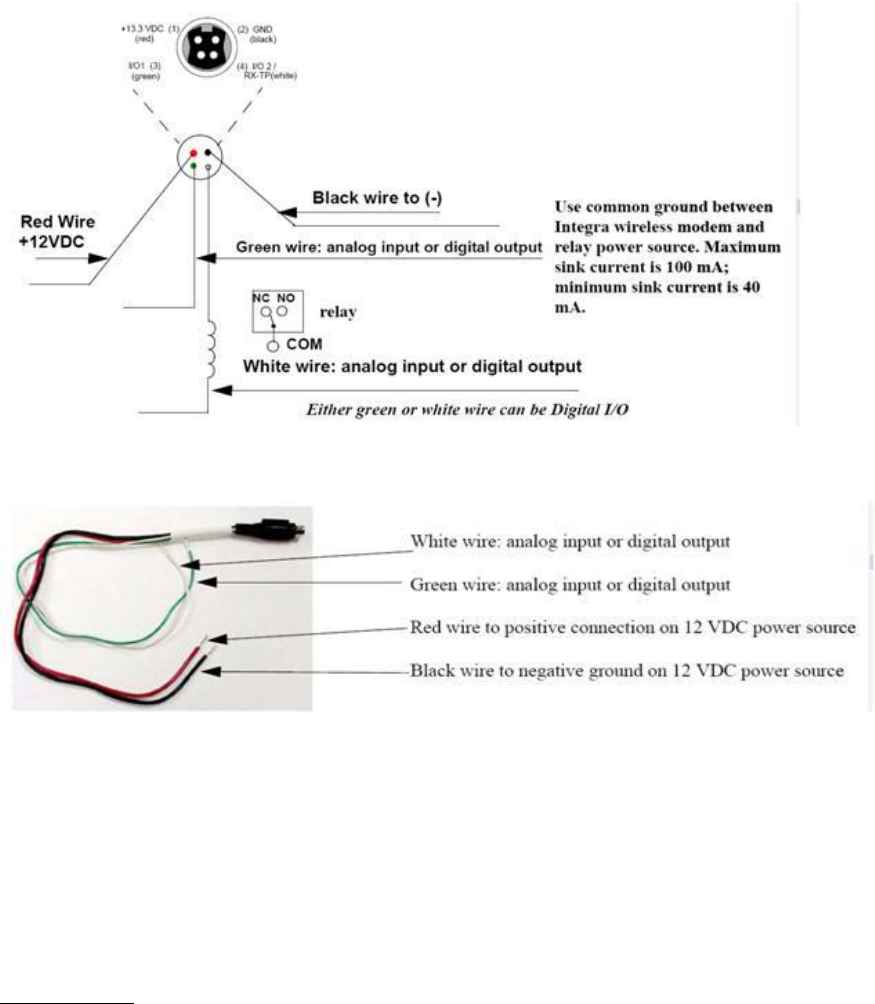
Digital Output Circuit and Interface Parameters
Hardware setup for the Integra-TR utilizing Digital I/O should be completed following the circuit diagram in Figure 20 and
the wire diagram in Figure 21.
Integra-TR User Manual Page | 32
Figure 20 - Digital I/O Circuit Diagram
Figure 21 - Integra Power I/O Cable
From COM/Analog Operating Parameters screen (see Figure 18 and Figure 22), select Digital Output for the External I/O to
be interfaced with user application. Figure 21 shows External I/O 2 (white wire) as chosen Digital Output. If desired,
External I/O 1 (green wire) is utilized by choosing External I/O 1. Select Utilities from tool bar and select Offline Diagnostics.
The Offline Diagnostics screen provides the interface to select the Modem ID for the desired Remote Unit. Figure 22 shows
28 as an example. Click Get Diags button. External I/O 1 diagnostics shows the output’s status. Figure 22 shows External I/O
1 operating at 0.1 volt with External I/O 2 ON (grounded). The External I/O status changes as the selection box is checked.
Selection boxes will show and affect changes to selected unit it Modem Select when Get Diags is clicked. If Local ID is
selected, Get Diags will return the status of the local Integra.
Channel Select 1
Integra-TR User Manual Page | 33
For use in Integras not equipped with the cooling option - setting this option will configure the connection to be an analog
input for 2 or 4 Channel Select Mode. If Channel Select 2 is NOT selected, this input and Channel Select 2 input selects
between Channels 1, 2, 3 and 4. A low level (logic 0) is a voltage less than the Channel Select Voltage and a high level (logic
1) is a voltage greater than the Channel Select Voltage. The Channel Select Voltage is selected on the Radio Tab. For 2
Channel Select Mode, see Table 7 "4 Channel Select Mode".
Note: If configured as a Digital Output, the open-collector transistor requires an external pull-up (i.e., resistor) to a voltage
of 2 to 10 volts.
Integra-TR User Manual Page | 34
Note: Multi-Channel operation is available in modem firmware 2.20 or later.
Tx Controlled Fan Timeout
Tx Controlled Fan Timeout is used to set the interval of time the unit will keep the fan turned ON after a transmission is
completed. The range is 5 to 255 seconds in 1 second intervals.
Figure 22 - Integra Field Programming Software Digital I/O Screens
External I/O 2 (White)
These radio buttons select configuration of Pin 4 of the Power - I/O Connector (white wire):
Analog Input - for use on units not equipped with the cooling option - can be used to monitor an external
voltage (0 to 10 volts).
Rx TP Output - performs as the demodulated signal level test point. The Rx TP level is half of the internal Rx
Test Point.
Ant. SW Control - supports the use of a redundant base station. Ant. SW Control configuration is dependent on
hardware configuration and should not be changed in the field.
Digital Output - This connection can be used to control the open-collector transistor on the connector. The
open-collector output can sink a maximum current of 40 mA when the modem board rev is 0 and 100 mA
when the modem board rev is 1. The output is controlled from the Offline Diagnostics screen NOTE: When
configured as a Digital Output, the open-collector transistor requires an external pull-up (i.e., resistor) to a
voltage of 2 to 10 volts.
Channel Select 2
Selecting the Channel Select 2 option will configure the connection to be an analog input for 2 or 4 Channel Select Mode. If
Channel Select 1 IS NOT selected, this input selects between Channels 1 and 2. If Channel Select 1 IS selected, this input and
Channel Select 2 input selects between Channels 1,2,3 and 4. A low level input and Channel Select 2 input selects between
channels 1,2,3 and 4. A low level (logic 0) is a voltage less than the Channel Select Voltage and a high level (logic 1) is a
Integra-TR User Manual Page | 35
voltage greater than the Channel Select Voltage. Channel Select Voltage is selected on the Radio Tab. For 2 Channel Select
Mode, a low level input will select channel 1 and a high level will select Channel 2. For 4 Channel Select Mode, see Table 7.
Note: When configured as a Digital Output, the open collector transistor requires an external pull-up (i.e., resistor) to a
voltage of 2 to 10 volts.
Note: Multi-Channel operation is available in modem firmware version 2.20 and later.
Table 7 - 4 Channel Select Mode
Channel Select 2
Channel Select 1
Channel 1
low
low
Channel 2
low
high
Channel 3
high
low
Channel 4
high
high
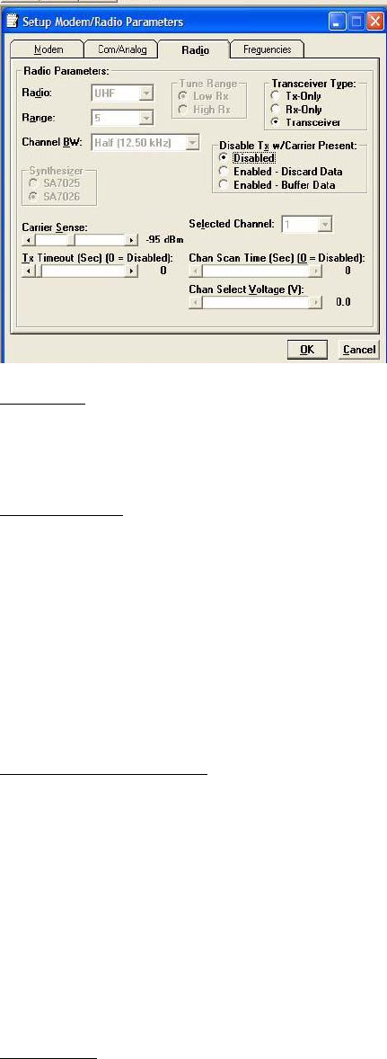
3.4.2.3 RADIO OPERATING PARAMETERS
The Radio tab allows user programming of various radio operating parameters.
Radio
This field designates the radio model.
Range
This field designates radio frequency range.
Channel Bandwidth
This field specifies whether the unit is half-channel (12.5 kHz) or full-channel (25 kHz).
Synthesizer
Synthesizer displays the type of synthesizer used on the RF circuit board (SA7025 or SA706).
Figure 23 - Radio Setup Parameters Screen
Integra-TR User Manual Page | 36
Tune Range
For UHF Range 0 25 kHz units only: Tune Range allows setting of the Integra-TR to the low or high end of the frequency
(242-4048-030: 406.1-422 MHz Low Rx, 242-4048-031: 414-430 MHz High Rx).
Transceiver Type
These radio buttons configure the transmitting and receiving characteristics of the unit according to the type of network
application:
Tx Only - For use in a full-duplex application to disable receptions on the unit used as the transmitter. Tx Only
designation pre-loads the synthesizer and allows faster attack time to speed up transmission response.
Rx Only - For use in a full-duplex application to disable transmissions on the unit used as the receiver. Rx Only
designation prevents accidental transmissions.
Transceiver - For use in all other applications.
Disable Tx w/Carrier Present
The Disable Tx w/Carrier Present provides the following options to configure unit reaction to an RF carrier presence when a
transmission is to begin:
Disabled - Select this option to instruct the unit to allow a transmission when a carrier is present.
Enabled (Discard data) - Select this option to instruct the unit not to allow a transmission if a carrier is present. Any
user data the unit receives on the COM Port while a carrier is present, is ignored and discarded.
Enabled (Buffer data) - Select this option to instruct the unit not to allow a transmission if a carrier is present. Any
user data the unit receives on the COM Port while a carrier is present is buffered and sent when the carrier is no
longer present.
Carrier Sense
Denotes the RSSI level when the unit senses a carrier. Carrier Sense is used for data recovery, in the interpretation of
diagnostics, and to turn on the front panel CS LED. The threshold may be raised to prevent false Carrier Sense operation in

Integra-TR User Manual Page | 37
the presence of noise, inter-modulation, or other sources of interference (i.e. for ambient noise at -100 dBm, set the Carrier
Sense for -95 dBm).
Tx Timeout
Tx Timeout is used to set maximum period of time the unit will allow in a transmission. The range is 0 to 120 seconds in 1
second intervals (0 being disabled). Tx Timeout is used to protect both the unit and the network in case a transmitter
becomes stuck on the air. For Integra-TRs equipped with the cooling option for extended transmit applications, the Tx
Timeout must be disabled. Warning: Disabling the timer may disrupt the network or damage the unit should it become
stuck in transmit due to excessive user data received on the COM port or the if the RTS signal remains active.
Selected Channel
This field allows the user to choose a selected channel pair for receiving and transmitting. Allowable entries are 1 to 16. The
selected channel will be used if Channel Select 1 and Channel Select 2 are NOT selected. (COM/Analog Tab). Note: This
feature is disabled when a Channel Select Line is enabled (green or white wire).
Chan Scan Time
Channel Scan Time allows the user to configure the modem to switch (increment from the Selected Channel) to a new
channel if it has not received a valid data packet for this programmable time. This is programmable in steps of 20 seconds
(60 to 5000 seconds, or 1 to 83 minutes). Setting Chan Scan Time to zero disables channel scan operation and the modem
remains on the selected channel. Note: This feature is disabled when Sleep/Suspend Period is enabled, when Master Mode
is enabled or when a Channel Select Line is enabled (green or white wire).
Chan Select Voltage
Chan Select Voltage allows the user to determine voltage thresholds for Channel Select 1 (green) and Channel Select 2
(white) inputs (if programmed). A low level (logic 0) is a voltage less than the set voltage threshold and a high level (logic 1)
is a voltage greater than the set voltage threshold. Note: Multi-Channel operation is available in modem firmware version
2.20 and later.
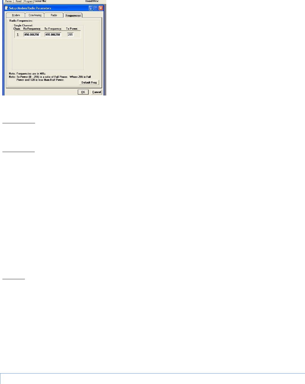
3.4.2.4 SETUP MODEM/RADIO PARAMETERS: FREQUENCIES TAB
Figure 24 - Frequencies Tab
Integra-TR User Manual Page | 38
The Frequencies Tab allows the user to program the radio channels (Frequency Pairs).
Rx Frequency
Rx Frequency designates channel receive frequency.
Tx Frequency
Tx Frequency designates channel transmit frequency. There are 6 VHF splinter channels available for quarter-channel VHF
(6.25 kHz) Integras. The frequencies for these splinter channels are:
154.456250 MHz
154.463750 MHz
154.471250 MHz
154.478750 MHz
173.203750 MHz
173.396250 MHz
Caution: If an Integra-TR is programmed on a splinter channel, care must be taken not to perform a Read and a Program
with Field Programming Software Version 2.05 or earlier. Users with splinter frequencies should confirm that they are using
Version 2.06 or later. To download the newest version, visit our website at www.calamp.com.
Tx Power
This field designates the channel pair Power Output Adjust value. The default value is 255 (5 watts). This value should be
left at the default value unless lower power is required to meet regulatory requirements, to increase the allowable transmit
duty cycle or to reduce transmit power. As the output is adjusted downward (less RF output power) the overall current
requirements of the Integra are lessened. When optimizing a system for operational parameters such as RF coverage and
over all power (current) usage, the correct amount of RF power needed for coverage may actually be less than full (5 watts)
output. This in turn can lower overall power (current) needs of the wireless modem.
NOTE: Power does not vary linearly with this parameter so some experimentation may be required to determine the
correct power setting.
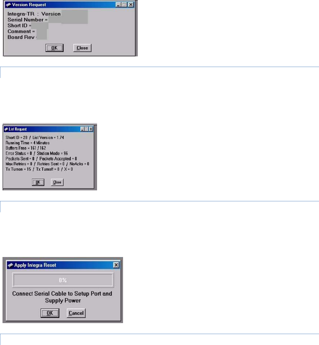
3.4.3 VERSION REQUEST
Integra-TR User Manual Page | 39
The Select Version Reset utility is accessed from the Edit pull-down menu. Selecting Version Request causes the Integra-TR
Field Programming Software to display information about the version of the Integra-TR hardware and firmware (see Figure
25).
Figure 25 - Version Request Screen
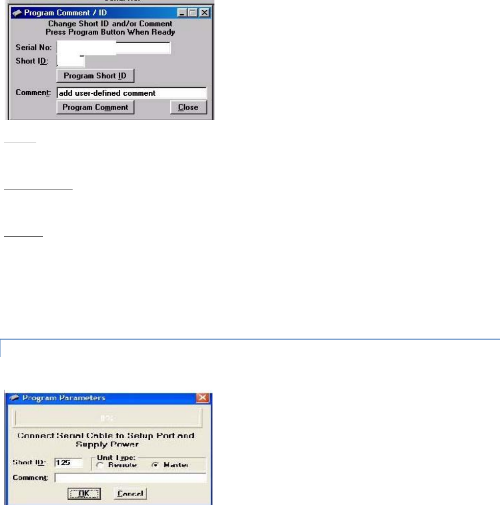
3.4.4 LIST INFORMATION
The List Information utility is accessed from the Edit pull-down menu. List Request is a diagnostic tool for the modem’s
firmware. The information is used if interfacing with Technical Services is necessary (See Figure 26).
Figure 26 - List Request Screen
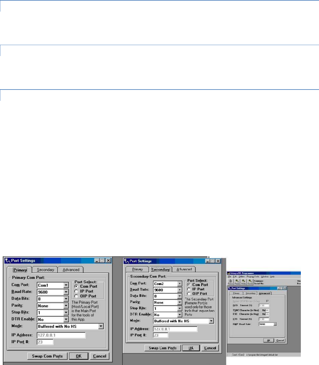
3.4.5 APPLY INTEGRA RESET
The Apply Integra Reset utility is accessed from the Edit pull-down menu. Integra Reset tells the Integra-TR to perform a
software reset. Performing a Station Reset reacts the same as cycling power to the unit (see Figure 27).
Figure 27 - Reset Screen
3.4.6 PROGRAM COMMENT/ID
Integra-TR User Manual Page | 40
The Program Comment/ID utility is accessed from the Edit pull-down menu. The Program Comment/ID field allows the user
to program a Short ID and/or Comment. This function is used if the Integra-TR to be programmed was cloned from another
unit (See Figure 28).
Figure 28 - Program Comment/ID Screen
Short ID
A number (from 1 to 254 and 256 to 1023 - 255 is reserved) that identifies an individual unit in a network.
Program Short ID
Clicking this button programs the new Short ID.
Comment
This field allows the user to give each unit a unique description (s), or add customer name, location, technical information,
or other user desired information. Comments must be text and are limited to 24 characters, including spaces.
3.4.7 PROGRAM PARAMETERS
Figure 29 - Program Parameters
Program Parameters allows the user to program the currently loaded programmable parameters to the Integra-TR (the ID
Number, Comment and Remote/Master settings are extracted from the fields on the screen). This option can be used for
programming the same Data File (.DAT) into multiple modems (if .dat file is imported into the parameters field, the Short
Integra-TR User Manual Page | 41
ID, Comment and Remote/Master settings will be changed - verify correct ID, Comment and Remote/Master BEFORE
clicking OK). At the completion of programming, the ID Number will automatically be incremented.
3.4.8 READ PARAMETERS
The Read Parameters function allows the user to view the programmable parameters that are currently programmed in the
Integra-TR.
3.4.9 COPY PARAMETERS
The Copy Parameters function allows the user to write the currently loaded programmable parameters to the Integra-TR
(including the ID Number, Comment and Remote/Master Settings).
3.4.10 COM PORT SETTINGS
Integra-TR programming is done through the PC’s Primary COM Port. Primary and secondary COM ports are configured with
the Field Programming Software. The programming cable (included in the Programming Kit - DRL part number 250-4008-
001) is connected from the Setup Port on the Integra-TR to the PC’s COM port configured as the Primary Port. The Port
Settings screen of the Field Programming Software is accessed via the Utilities pull-down menu (see Figure 30). The Port
Settings screens are used to configure the PC’s serial COM Ports. COM Port parameters are defined in 2.4.2.1. COM Port
assignments are displayed in the bottom status bar of the Integra-TR Field Programming Software screen.
Figure 30 - Port Settings Screen

Integra-TR User Manual Page | 42
3.4.10.1 PRIMARY COM PORT PARAMETERS
COM Port
Selects COM Port number (COM 1-4) for the Primary and Secondary COM ports (see Figure 30).
Baud Rate
Selects the communication speed for Primary and Secondary COM Ports.
Data Bits
Selects the number of data bits (7 or 8) transmitted or received for the Primary and Secondary COM Ports.
Parity
Selects transmission or reception of any Parity Bits for the Primary and Secondary COM Ports.
Stop Bits
Selects number of Stop Bits (1 or 2) transmitted or received for the Primary and Secondary COM Ports.
DTR Enable
Used to assert DTR (Data Terminal Ready) line of the RS232 Port when the port is open for the Primary and Secondary COM
Ports.
Mode
See Section 3.4.2.2.
IP Address
IP Address allows selection of an IP Address when IP Port is selected.. The Ethernet-to-RS-232 converter with this IP Address
must have a TCP (Telnet) server enabled.
IP Port #
IP Port Number allows the user to select the IP Port number used if the Port Select has IP Port selected. This is the Port
Number that will be used to make a TCP (Telnet) connection.
Port Select
Port Select allows the user to choose data transmissions and receptions on a specified RS-232 COM port or an Ethernet
adapter via TCP (Telnet).
Com Port - System data will be transmitted and received using the specified RS-232 COM port.
IP Port - System data will be transmitted and received over the Ethernet to a specified IP address and port number using
the TCP (Telnet) protocol. Select this option if an Ethernet to RS232 converter is implemented for the unit under test.
OIP Port - Feature not accessible with standard Integra-TR.
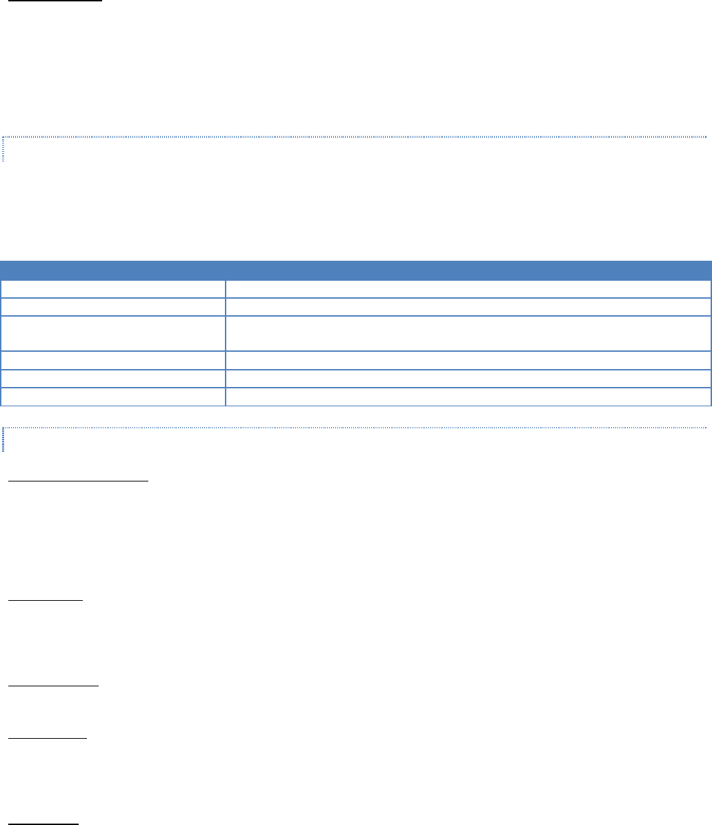
Integra-TR User Manual Page | 43
Swap COM Ports
Selecting the Swap Com Ports button moves the Secondary COM Port settings to the Primary COM Port (and moves the
Primary COM Port to the Secondary settings). Since Integra-TR programming is done through the Primary COM Port, this is
useful when two units are connected to the Primary and Secondary COM Ports. A Swap COM Ports allows the second unit
to be programmed without switching programming cables. Swap COM Ports is also selectable from the Utilities drop-down
menu.
3.4.10.2 PRIMARY AND SECONDARY PORT SETTINGS COMMUNICATIONS MODES
The Utilities drop down menu provides the tool to configure the communications mode for the Primary and Secondary PC
Port. See Table 8 for Communication Mode configurations.
Table 8 - Communications Mode
Mode
Description
Sync/ESC with No HS
Sends data using Sync/byte-stuffing protocol without handshaking.
Buffered with No HS
Sends buffered data without handshaking (this mode required for DOX operation.)
Sync/Esc with RTS/CTS HS
Sends data using the Sync/Esc byte-stuffing protocol with RTS/CTS hardware
handshaking.
Buffered with RTS/CTS HS
Sends buffered data with RTS/CTS hardware handshaking.
Sync/Esc with Flow Control HS
Sends data using the Sync/Esc byte-stuffing protocol with flow control handshaking.
Buffered with Flow Control HS
Sends buffered data with flow control hardware handshaking.
3.4.10.3 ADVANCED PORT SETTINGS
Ignore DCD Before Tx’ing
Ignore DCD before Tx’ing allows the user to check for an inactive DCD before transmitting. If selected, no data is sent until
DCD becomes active.
DCD Timeout
If Ignore DCD Before Tx’ing is selected, DCD Timeout determines the length of time to wait for DCD to become inactive
before data is sent. If the DCD does not become inactive during this time, the data is not sent.
SYNC Character SYNC Character allows the user to select the SYNC character when utilizing a Sync/Esc (Framing) Mode. The
Sync Character is the first character of a frame to be sent. This character is a HEX character.
ESC Character
ESC Character allows the user to select the ESC character when utilizing a Sync/Esc (Framing) Mode. The ESC Character
precedes any embedded SYNC or ESC characters that follow the initial SYNC character. This character is a HEX character.
CTS Timeout
CTS Timeout selects the RTS to CTS timeout when using an RTS/CTS hardware handshaking mode. This is the amount of
time (in 50mS increments) the software will allow for the CTS line to become active after asserting the RTS line.

Integra-TR User Manual Page | 44
TCP/IP Response
The TCP/IP Response allows the user to select the Response Time (in seconds) to allow for the Unit to respond to
Programming Commands over a TCP/IP Connection. The value of this may require the use of the About Utility. By pinging
the destination IP Address, the utility will give back Minimum / Maximum / Average Times it takes to send and receive a
packet over the TCP/IP Connection. A safe value will be to use the Maximum Time (in seconds).
DMP Baud Rate
DMP Baud Rate selects the communication speed for the Primary and Secondary COM Ports when using the DMP protocol.
This protocol is used to talk to the Integra modems through the Setup Port.
SYNC/ESC Framing
A typical SYNC/ESC frame will look like the following character stream.
SYNC ML Data0 ------ DataN Chksum
8 bits 8 bits 8 bits ------ 8 bits 8 bits
And the following definitions are made:
SYNC (8 bits)
Marks the start of a frame when not preceded by and ESC character. When using a Sync/Esc (Framing) Mode, the software
will stuff this character automatically.
ML (8 bits)
The length of frame is given by ML. ML is the number of characters left to be received including the checksum but excluding
any ESC characters added as part of the protocol. When using a SYNC/ESC (Framing) Mode, the software will stuff this
character automatically (based on the number of data characters).
Data 0 - N (8 bits each)
Frame information.
Chksum (8 bits)
This is the 8 bit 2s complement of the sum of the frame less the SYNC character and any additional ESC characters added
(ignoring the carry out of the high order bits. When using a SYNC/ESC (Framing) Mode, the software will stuff this character
automatically.
3.4.11 SWAP COM PORTS
Selecting Swap Com Ports from the Utilities drop-down menu moves the Secondary COM Port settings to the Primary COM
Port (and moves the Primary COM Port to the Secondary settings). Since Integra-TR programming is done through the
Primary COM Port, this is useful when two units are connected to the Primary and Secondary COM Ports. A Swap COM
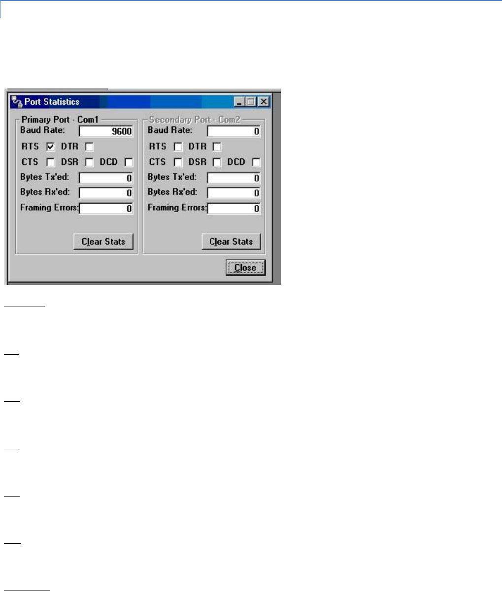
Integra-TR User Manual Page | 45
Ports allows the second unit to be programmed without switching programming cables. Swap COM Ports is also selectable
from the Port Settings Primary and Secondary Port screens.
3.4.12 PORT STATISTICS
Port Statistics are accessed from the Utilities pull-down menu and show the current parameters of the PC’s Primary and
Secondary COM ports.
Figure 31 - Port Statistics Screen
Baud Rate
Baud Rate shows the current setting for the utilized COM port.
RTS
RTS shows the current state of the RTS (request to send) line. RTS is an output from the PC.
DTR
DTR shows the current state of the DTR (data terminal ready) line. DTR is an output from the PC.
CTS
CTS shows the current state of the CTS (clear to send) line. CTS is an input to the PC.
DSR
DSR shows the current state of the DSR (data set ready) line. DSR is an input to the PC.
DCD
DCD shows the current state of the DCD (data carrier detect) line. DCD is an input to the PC.
Bytes Tx’ed

Integra-TR User Manual Page | 46
Bytes Transmitted shows the number of bytes (characters) transmitted since the port was last opened.
Bytes Rx’ed
Bytes Received shows the number of bytes (characters) received since the port was last opened.
Framing Errors
Framing Errors shows the number of Framing Errors received since the port was last opened.
3.4.13 OFFLINE LINK TEST
The Offline Link Test utility is accessed from the Utilities pull-down menu. The Offline Link Test is used to test the link
between two units: the local unit interfaced to the computer and a remote unit. Blocks of data are transmitted to the
remote unit and the remote unit decodes and returns them. The transmitted and received blocks of data are compared and
the ratio of the results is calculated. NOTE: An Offline Link Test requires suspension of user network operation.
Local ID
The Local ID is the Short ID of the unit connected to the computer.
Remote ID
The Remote ID combo box allows selection of the unit (by choosing its Remote ID) from which the Link Test information is
gathered. Remote IDs are set up in the Diagnostic IDs and Alarms Screen.
Figure 32 - Offline Link Test Screen

Integra-TR User Manual Page | 47
An Offline Link Test returns the following statistics:
Blocks Tx’ed to Remote
Blocks Tx’ed to Remote displays the number of data blocks transmitted to the remote unit.
Responses from Remote
Responses from Remote displays the number of responses heard from the remote unit.
Blocks Rx’ed from Remote
Blocks Rx’ed from Remote displays the number of data blocks received from the remote unit.
Link Quality to Remote
Link Quality to Remote displays the receive quality of the remote unit; the number of correctly decoded transmissions
received by the remote divided by the number of total transmissions detected by the remote (in %).
Link Quality from Remote
Link Quality from Remote displays the ratio of data blocks received to data blocks transmitted (in %).
Overall Link Quality
Overall Link Quality displays the overall link quality by combining the Link Quality to Remote ratio with the Link Quality from
Remote ratio (in %).
# of Blocks to Send
# of Blocks to Send allows the user to determine the number of blocks to send before stopping (with 0 being disabled).
Block Delay (s)
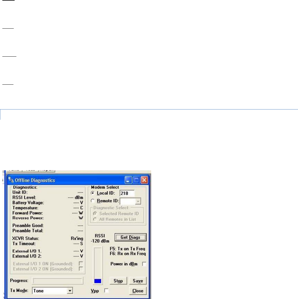
Integra-TR User Manual Page | 48
Block Delay (s) allows the user to determine the delay between the transmission of data blocks in 0.25 second intervals
(0.00 to 10.00 seconds).
Clear
Clear allows the user to clear the display (blocks transmitted, responses received, blocks received and link quality).
Start
Start is used to begin the test.
Pause
Pause is used to pause the test and allows the user to resume the test at a later time.
Save
The Save button allows the user to save the current Offline Link Test results to a file.
3.4.14 OFFLINE DIAGNOSTICS
Offline Diagnostics are accessed from the Utilities pull-down menu. Offline Diagnostics are returned from a local or remote
unit in response to a Get Diags request (see Figure 33). An Offline Diagnostics request requires suspension of user network
operation.
Figure 33 - Offline Diagnostics Screen
Offline Diagnostics parameters include the following:

Integra-TR User Manual Page | 49
Unit ID: the Short ID of the unit sending diagnostics.
RSSI Level: Received Signal Strength Indication (in dBm).
Battery Voltage: supply voltage.
Temperature: internal case temperature (in Celsius).
Forward Power: Forward Power (in watts or dBm).
Reverse Power: Reverse Power (in watts or dBm).
Preamble Good: the number of correctly decoded transmissions received in the last 15. Used with Preamble Total,
this serves as an indication of how well the unit is receiving data.
Preamble Total: the number of total transmissions detected, maximum is 15. Used with Preamble Good, this
serves as an indication of how well the unit is receiving data.
XCVR Status: displays the status of the transceiver.
Tx Timeout: A request for a remote unit to transmit causes the unti to transmit on the programmed transmit
frequency until the Tx Timeout Timer expires. Program the Tx Timeout Timer in the Setup Modem/Radio
Parameters/Radio Tab.
Progress: The Progress panel shows the progress of the Get Diags request.
Tx Mode: The Tx Mode combo box allows the user to select different transmit modes when the unit is told to
transmit:
o Tone: the unit will transmit a 1200 Hz tone.
o Mod Balance: the unit will transmit a 100 Hz square wave.
o Random Data: the unit will transmit random data.
o No Modulation: the unit will transmit with no modulation.
External I/O 1 (Pin 3 - Green Wire): When the I/O 1 connection of the Power - I/O Connector is configured as a
Digital Output, External I/O displays the state of the open-collector transistor (ON-Grounded/OFF-Open). If
configured as an Analog Input, External I/O displays the voltage on the connector (in volts). Programming of
External I/O 1 is performed in the Setup Modem/Radio Parameters screen.
External I/O 2 (Pin 4 - White Wire): When the I/O 2 connection of the Power - I/O Connector is configured as a
Digital Output, this displays the state of the open-collector transistor (ON - Grounded / OFF - Open). If configured
as Analog Input, External I/O 2 displays the voltage on the connector (in volts). Programming of the External I/O 2
is performed in the Setup Modem/Radio Parameters screen.
External I/O 1 ON (Grounded): When the I/O 1 connection of the Power - I/O Connector is configured as a Digital
Output, this checkbox is enabled to allow for the change of state of the open-collector output of Pin 3. Clicking on
this check box causes immediate action to change the state of the output. This is true for local or a selected
remote ID.
External I/O 2 ON (Grounded): When the I/O 2 connection of the Power - I/O Connector is configured as a Digital
Output, this checkbox is enabled to allow for the change of state of the open-collector output on Pin 4. Clicking on
this check box causes immediate action to change the state of the output. This is true for local or a selected
remote ID.
Modem Select
Local ID
The Local ID button allows the user to send commands to the local unit (the unit interfaced to the computer). The Short ID
for this unit is shown.
Remote ID

Integra-TR User Manual Page | 50
The Remote ID button allows the user to send diagnostic commands to any specific remote unit and obtain its diagnostic
information. The Remote ID is selected from the list of Remote IDs set up in the Diagnostic IDs and Alarms screen.
Diagnostic Select / Selected Remote ID
This button allows the user to gather Offline Diagnostics from the selected Remote ID only.
Diagnostic Select / Remote ID List
This button allows the user to gather Offline Diagnostics from all the IDs in the list of Remote IDs (including the local unit).
Get Diags
The Get Diags button allows the user to send the command for Offline Diagnostics. The command is sent to the unit
connected to the computer if the Local ID button is selected. The command is sent to the selected Remote ID if the Remote
ID and Selected Remote ID buttons are selected. The command is sent to the list of Remote IDs if the Remote ID and
Remote ID List buttons are selected.
Stop
The Stop button allows the user to stop any commands for Offline Diagnostics from being sent.
Save
The Save button allows the user to save the current Offline Diagnostics to a text file.
RSSI/Pwr
The RSSI/Pwr panel shows the current RSSI level (in dBm) while the local unit is receiving and the current Power Level (in
watts or dBm) while the local unit is transmitting.
Rev Pwr
The Rev Pwr check box allows the user to view the reverse power instead of forward power while the local unit is
transmitting.
F5
Pressing the F5 key will cause the unit to transmit on the programmed transmit frequency.
F6
Pressing the F6 key will cause the unit to go to receive on the programmed receive frequency.
Note: Commanding a remote unit to transmit will cause the unit to transmit on the programmed transmit frequency until
the Tx Timeout Timer expires. Be sure to program the Tx Timeout Timer in the Setup Modem/Radio Parameters Screen (see
Figure 16).
3.4.15 ONLINE DIAGNOSTICS
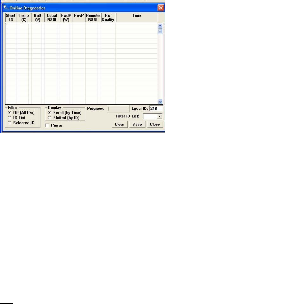
Integra-TR User Manual Page | 51
Online Diagnostics are accessed from the Utilities pull-down menu. Online Diagnostics are transmitted by each unit in a
network before the user’s data is transmitted. All units must be programmed with the Online Diagnostics parameter found
on the Setup Modem/Radio Parameters screen to receive Diagnostics from a system. The unit that the computer is
interfaced with will output Online Diagnostics as they are received. Using Online Diagnostics does not require suspension of
network operation.
Online Diagnostics are subject to alarm conditions defined in the Diagnostic IDs and Alarms screen (see Figure 34). When
Online Diagnostics are received and a diagnostic field falls outside the alarm limits, a “<“ character will designate a value
less than the low alarm and a “>” character will designate a value greater than the high alarm.
Figure 34 - Online Diagnostics
The following Online Diagnostics are gathered:
Short ID: The Short ID displays the Short ID of the unit transmitting the diagnostics.
Temp: Temp displays the internal case temperature (in Celsius) of the unit transmitting the diagnostics.
Batt: Batt displays the supply voltage (in volts) of the unit transmitting the diagnostics.
Local RSSI: If these are the diagnostics from a Remote Station, Local RSSI indicates the RSSI level of the Local
Station obtained by the Remote Station transmitting these diagnostics. If these are the diagnostics from the Local
Station, Local RSSI indicates the RSSI level of the Local Station from the last transmission of a Remote Station.
FwdP: FwdP displays the forward power (in watts) of the unit transmitting the diagnostics.
RevP: RevP displays the approximate measure of reverse (reflected) power of the unit transmitting the diagnostics.
This is represented as “Good” if the reverse power is within acceptable limits and is represented as “Bad” if the
reverse power is too high. The threshold is set to approximately 1/4 the forward power.
Remote RSSI: If these are the diagnostics from a Remote Station, Remote RSSI indicates the RSSI level of the
Remote Station from the last received transmission. If these are diagnostics from the Local Station, Remote RSSI
indicates the RSSI level of the Remote Station last received at the local Station.
Rx Quality: Rx Quality displays the receive quality (in %) of the remote unit. This is the number of correctly
decoded transmissions received (in the last 15) divided by the number of total transmissions detected.
Time

Integra-TR User Manual Page | 52
Time is the time stamp when the diagnostics were received.
Filter
Filter allows the user to filter Short IDs. The following options are available:
Off (All IDs): no IDs are filtered out.
ID List: only the IDs in the Filter ID List are shown.
Selected ID: only the selected ID in the Filter ID List is shown.
Display
Display allows the user to format on screen data. The following options are available:
Scroll (by time): displays the diagnostics as they are received.
Slotted (by ID): sorts the diagnostics by Short ID. Using this option, each Short ID will have one row of diagnostics,
showing the most recent.
Progress
The Progress panel shows the sorting progress of the diagnostics if a filter was changed.
Local ID
The Local ID is the Short ID of the unit interfaced with the PC.
Filter ID List
Filter ID List is a listing of Remote IDs setup in the Diagnostic IDs and Alarms Screen. This list is used for selecting a filter.
Pause
The Pause button allows the user to pause the reception of the diagnostics for scrolling through the grid.
Clear
The Clear button allows the user to clear the display and current Online Diagnostics.
Save
The Save button allows the user to save the current Online Diagnostics to a file. A maximum of 4096 lines of data can be
saved.
3.4.16 DIAGNOSTIC IDS AND ALARMS
The Diagnostics IDs and Alarms utility is accessed from the Utilities pull-down menu. The Diagnostics IDs and Alarms screen
allows the user to set up the ID List for use with the Offline Link Test, and Offline and Online Diagnostics as well as Alarms
for use with Online Diagnostics.
Figure 35 - Diagnostic IDs and Alarms Screen
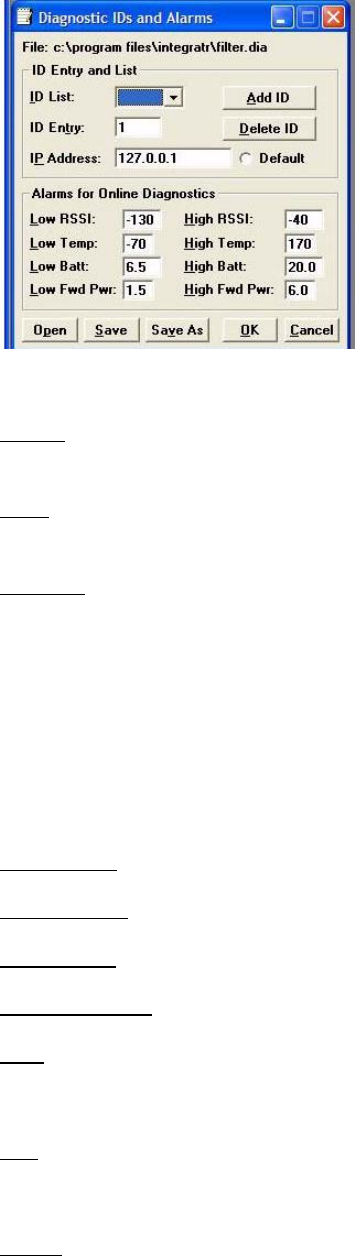
Integra-TR User Manual Page | 53
ID Entry and List
ID Entry: Allows the user to add Short IDs to the ID List. The range of this field is 1 to 1023 (ID 255 is reserved). A Short ID is
added to the ID list by hitting Enter or by pressing the Add ID button.
ID List: Allows the user to select a Short ID from the list to delete. A Short ID is deleted from the list by pressing the Delete
ID button.
IP Address:
IP Address allows the user to receive diagnostics through a serial to Ethernet converter with this IP Address. Default allows
the user to select a default unit for the diagnostics when received through a serial to Ethernet converter.
Alarms for Online Diagnostics
Alarm indications are available with Online Diagnostics. When Online Diagnostics are received and a diagnostic field falls
outside the Alarm limits, a “<“ character will designate a value less than the low Alarm and a “>” character will designate a
value greater than the High Alarm (See Figure 35).
Low/High RSSI: Low/High RSSI represent the low and high limits for the RSSI diagnostics (in dBm).
Low/High Temp: The Low/High Temp represents the low and high limits for the temperature diagnostics (in degrees C).
Low/High Batt: Low/High Batt represents the low and high limits for the battery voltage diagnostics (in volts).
Low/High Fwd Pwr: Low/High Pwr represents the low and high limits for the forward power diagnostics (in watts).
Open
The Open button allows the user to load Diagnostic IDs and Alarms from a previously saved file.
Save
The Save button allows the user to save the current Diagnostic IDs and Alarms to the current file.
Save As
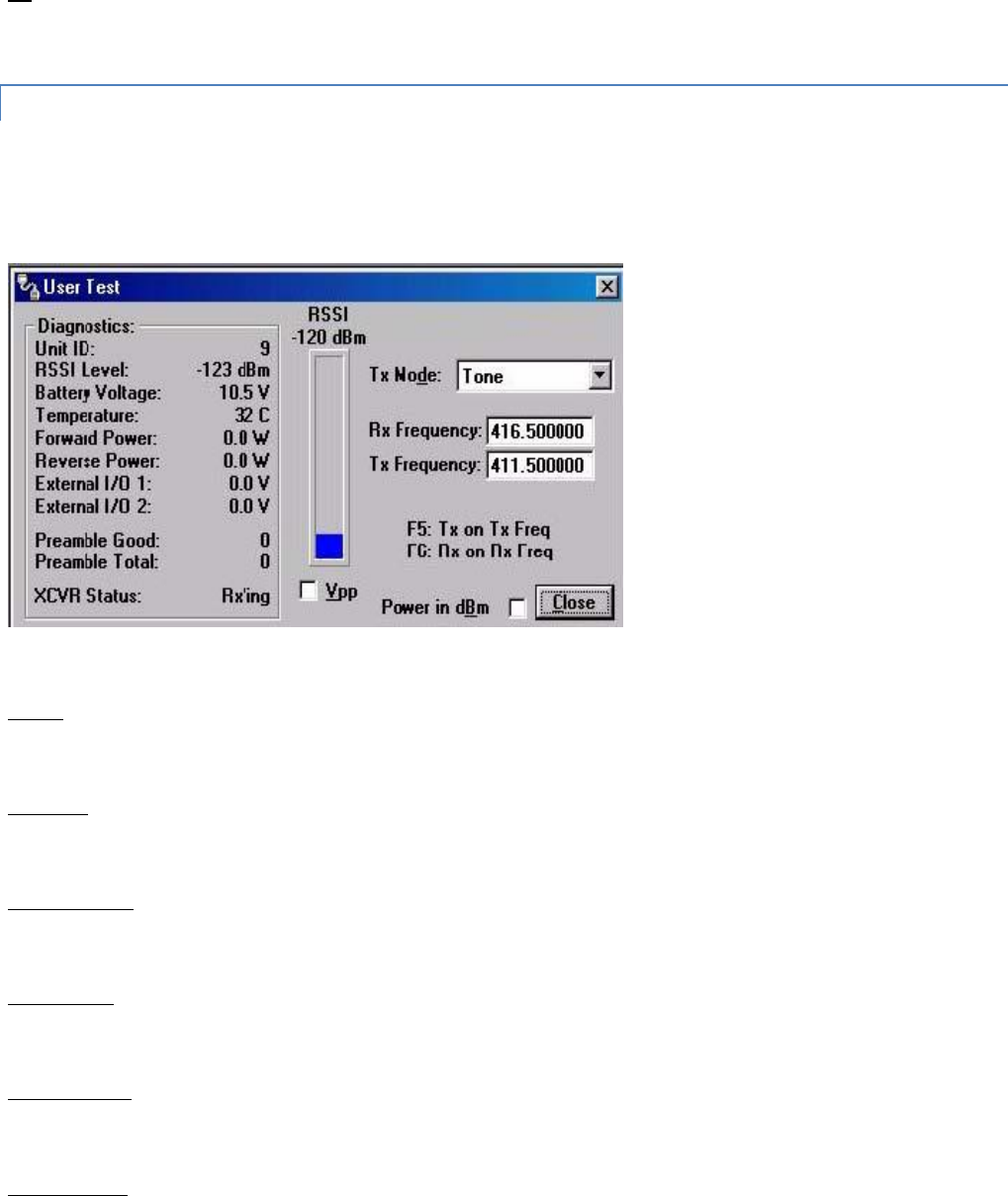
Integra-TR User Manual Page | 54
The Save As button allows the user to save the current Diagnostic IDs and Alarms to a name different than the current file.
OK
Selecting OK closes the Diagnostic IDs and Alarms window.
3.4.17 USER TEST
The User Test Utility is accessed from the Utilities pull-down menu. The User Test utility is an Offline function and requires
suspension of network operation.
Figure 36 - User Test Screen
A User Test’s diagnostic parameters include:
Unit ID
The Unit ID is the Short ID of the unit from which the diagnostics were received.
RSSI Level
Received Signal Strength Indication (in dBm).
Battery Voltage
Supply voltage (in volts).
Temperature
Internal temperature (in degrees Celsius).
Forward Power
Forward power (in watts or dBm).
Reverse Power

Integra-TR User Manual Page | 55
Reverse power (in watts or dBm).
External I/O 1
Voltage on the External I/O 1 Input from the Power - I/O Connector (in volts).
External I/O 2
Voltage on the External I/O Input from the Power - I/O Connector (in volts).
Preamble Good
The number of correctly decoded transmissions received in the last 15. Used with Preamble Total, this serves as an
indication of how well the unit is receiving data.
Preamble Total
The number of total transmissions detected, maximum is 15. Used with Preamble Good, this serves as an indication of how
well the unit is receiving data.
RSSI /Pwr
This panel shows the current RSSI level (in dBm) while the local unit is receiving and the current power level (in watts or
dBm) while the local unit is transmitting.
Rev Pwr
This check box changes forward power to reverse power on the Power Panel from while the local unit is transmitting.
Power in dBm
This check box allows the user to view Fwd/Rev Power in dBm (instead of watts).
Tx Mode
This box allows the user to select different transmit modes when the unit is told to transmit.
Tone - the unit transmits a 1200 Hz tone
Mod Balance - the unit transmits a 100 Hz square wave
Random Data - the unit transmits random data
No Modulation - the unit transmits a carrier with no modulation
Rx / Tx Frequency
Rx / Tx Frequency shows the current transmit frequencies.
F5
Pressing the F5 key will cause the unit to transmit on the programmed transmit frequency.
F6
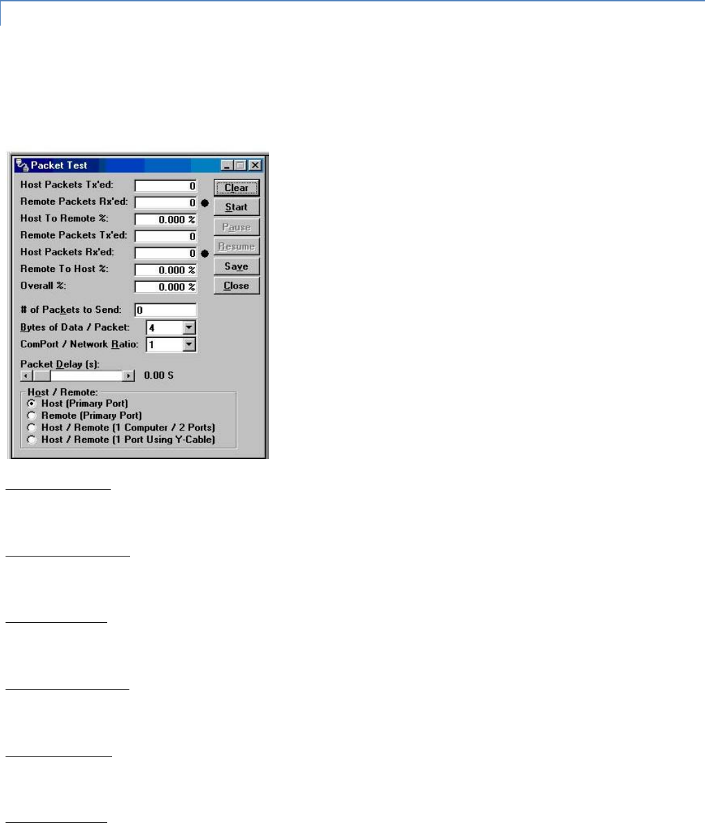
Integra-TR User Manual Page | 56
Pressing the F6 key will cause the unit to go to receive on the programmed receive frequency.
3.4.18 PACKET TEST
The Packet Test allows the user to simulate a Host/Remote polling environment. The Host will send out a packet to the
Remote and the Remote will reply to the Master with the same packet information. This test is useful for testing the
modem link.
Figure 37 - Packet Test Screen
Host Packets Tx’ed
Host Packets Tx’ed shows the number of data packet the Host device sent to the Remote.
Remote Packets Rx’ed
Remote Packets Rx’ed shows the number of data packets the Remote device successfully received from the Host.
Host to Remote %
Host to Remote % shows the number of data packets the Remote device has successfully sent to the Remote.
Remote Packets Tx’ed
Remote Packets Tx’ed shows the number of data packets the Remote device sent back to the Host.
Host Packets Rx’ed
Host Packets Rx’ed shows the number of data packets the Host device successfully received from the Remote.
Remote to Host %

Integra-TR User Manual Page | 57
Remote to Host % shows the percentage of data packets the Remote device successfully sent to the Host.
Overall %
Overall % shows the percentage of Host received packets versus Host transmitted packets.
# of Packets to Send
# of Packets to Send is a programmable number to tell the Host how many data packets to send to the Remote. After the
programmed number of data packets are sent, the transmission will automatically stop.
Bytes of Data/Packet
Bytes of Data/Packet is a programmable number to tell the Host the number of data bytes to send in each packet. The
Remote will respond with the same number of data bytes received.
COM Port/ Network Radio
Com Port/Network Radio is the ratio of COM Port baud rate to network (over-the-air) baud rate of the modem. This is used
if the network baud rate is slower than the COM Port baud rate. If the COM Port baud rate is 9600 and the network baud
rate is 4800, set the ratio to 2. If the COM Port baud rate and the Network Baud Rate are the same, set the Ratio to 1.
Packet Delay (s)
Packet Delay (s) tells the Host the number of seconds to delay between sending each data packet (range is from 0.00 to
10.00 seconds in 0.25 second intervals).
Host/Remote
Host/Remote allows the user to choose the COM Port configuration.
Host (Primary Port) - Configure the Primary COM Port as the Host device (the device initiating packets to the Remote
device).
Remote (Primary Port) - Configure the Primary COM Port as the Remote device (the device responding to the packets from
the Host device.
Host/Remote (1 computer / 2 ports) - Configure the Primary COM Port as the Host device and the Secondary COM Port as
the Remote device. A computer with 2 COM Ports is required for this option.
Host/Remote (1 Port using a Y-cable) - A computer with 1 COM Port is typical for this option (See Table 9). Configure the
Primary COM Port as the Host and Remote device. A Y-cable is required for this option (where Tx connections are split out
to the transmitting device and the Rx connections are split out to the receiving device).
Table 9 - Y-Cable Connections
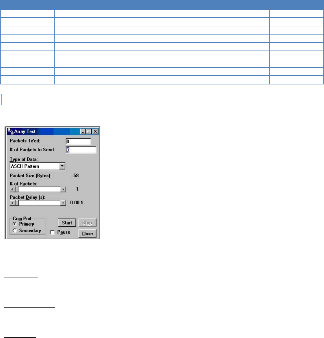
Integra-TR User Manual Page | 58
Pin Name
DB-9
DB-25
Computer
Rx
Tx
DCD
1
8
X
X
-
RxD
2
3
X
X
-
TxD
3
2
X
-
X
DTR
4
20
-
-
-
GND
5
7
X
X
X
DSR
6
6
-
-
-
RTS
7
4
X
-
X
CTS
8
5
X
-
X
RI
9
22
-
-
-
3.4.19 ARRAY TEST
Figure 38 - Array Test Screen
The Array Test utility is used to send programmable length test packets. The packets are built using one of four possible
patterns.
Packets Tx’ed
Packets Tx’ed shows the total number of data packets transmitted.
# of Packets to Send
# of Packets to Send shows the number of data packets to send before stopping (the range is 0 to unlimited).
Type of Data
Type of Data identifies the data pattern for each data packet. The size and format for each pattern is shown in the pattern
descriptions.
Pattern Descriptions -
Integra-TR User Manual Page | 59
ASCII Pattern
The ASCII Pattern Packet are 58 characters in length and have a sequence number at the beginning of each string, starting
at 000, incrementing to 999 and wrapping around to 000 again. The pattern used to build the packets should have the
following format (in ASCII):
000 ABCDEFGHIJKLMNOPQRSTUVWXYZabcdefghijklmnopqrstuvwxyz
001 ABCDEFGHIJKLMNOPQRSTUVWXYZabcdefghijklmnopqrstuvwxyz
- - -
998 ABCDEFGHIJKLMNOPQRSTUVWXYZabcdefghijklmnopqrstuvwxyz
999 ABCDEFGHIJKLMNOPQRSTUVWXYZabcdefghijklmnopqrstuvwxyz
000 ABCDEFGHIJKLMNOPQRSTUVWXYZabcdefghijklmnopqrstuvwxyz
001 ABCDEFGHIJKLMNOPQRSTUVWXYZabcdefghijklmnopqrstuvwxyz
ASCII Number Pattern
The ASCII Number Pattern are 54 characters in length and have a sequence number at the beginning of each
string, starting at 000, incrementing to 999 and wrapping around to 000 again. The pattern used to build the
packets should have the following format (in ASCII):
000 00 11 22 33 44 55 66 77 88 99 AA BB CC DD EE FF
001 00 11 22 33 44 55 66 77 88 99 AA BB CC DD EE FF
- - -
998 00 11 22 33 44 55 66 77 88 99 AA BB CC DD EE FF
999 00 11 22 33 44 55 66 77 88 99 AA BB CC DD EE FF
000 00 11 22 33 44 55 66 77 88 99 AA BB CC DD EE FF
001 00 11 22 33 44 55 66 77 88 99 AA BB CC DD EE FF
Binary Pattern
Binary Pattern packets are 16 characters in length and have a sequence number every 16 characters, starting at
0x00, incrementing to 0xFF and wrapping around to 0x00 again. The pattern used to build the packets should have the
following format (in Hex):
00 11 22 33 44 55 66 77 88 99 AA BB CC DD EE FF
01 11 22 33 44 55 66 77 88 99 AA BB CC DD EE FF
02 11 22 33 44 55 66 77 88 99 AA BB CC DD EE FF
-- 11 22 33 44 55 66 77 88 99 AA BB CC DD EE FF
FE 11 22 33 44 55 66 77 88 99 AA BB CC DD EE FF
FF 11 22 33 44 55 66 77 88 99 AA BB CC DD EE FF
00 11 22 33 44 55 66 77 88 99 AA BB CC DD EE FF
01 11 22 33 44 55 66 77 88 99 AA BB CC DD EE FF
02 11 22 33 44 55 66 77 88 99 AA BB CC DD EE FF
-- 11 22 33 44 55 66 77 88 99 AA BB CC DD EE FF
Random Binary Pattern
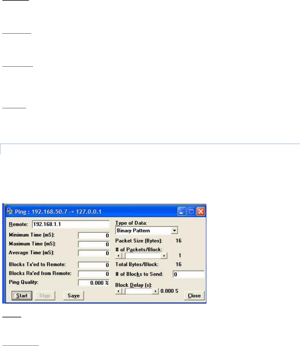
Integra-TR User Manual Page | 60
Random Binary Pattern is 16 characters in length and contain random binary data.
Packet Size
Packet Size shows the number of data bytes in each packet (described in Pattern Descriptions above).
# of Packets
# of Packets shows the number of packets in each transmission.
Packet Delay
Packet Delay shows the amount of time (in seconds) to delay between each packet transmission (range is from
0.00 to 30.00 seconds in 0.25 second intervals).
COM Port
COM Port allows the user to select which COM port (Primary or Secondary) is used for transmitting data.
3.4.20 PING TEST
For user convenience, the PING Test was added to the Integra FPS as a utility and is used to simulate a Host/Remote polling
environment. The Master sends out a packet to the Remote and the Remote replies to the Master with the same packet
information. This utility is useful for testing Ethernet and modem links.
Figure 39 - Ping Test Screen
Remote
Remote displays the IP Address of the device under test.
Minimum Time

Integra-TR User Manual Page | 61
Minimum Time displays the minimum amount of time taken for the Ping Packet to echo back from the Remote
device (in milliseconds).
Maximum Time
Maximum Time displays the maximum amount of time taken for the Ping Packet to echo back from the Remote device (in
milliseconds).
Average Time
Average Time displays the average amount of time taken for the Ping Packet to echo back from the Remote device
(in milliseconds).
Blocks Tx’ed to Remote
Blocks Tx’ed to Remote displays the number of data packets sent to the Remote device.
Blocks Rx’ed from Remote
Blocks Rx’ed from Remote displays the number of data packets received from the Remote device.
Ping Quality
Ping Quality displays the overall percentage of data packets sent vs. data packets received during the Ping Test.
Type of Data
Type of Data displays the type of Data Pattern to be used for each packet. The size for each Data Pattern is shown below in
Packet Size. The following lists the formats of the Data Patterns:
ASCII Pattern
The packets will be 52 characters in length. The pattern used to build the packets will have the following format (in
ASCII):
ABCDEFGHIJKLMNOPQRSTUVWXYZabcdefghijklmnopqrstuvwxyz
ABCDEFGHIJKLMNOPQRSTUVWXYZabcdefghijklmnopqrstuvwxyz
---
ABCDEFGHIJKLMNOPQRSTUVWXYZabcdefghijklmnopqrstuvwxyz
ASCII Number Pattern
The packets will be 48 characters in length. The pattern used to build the packets will have the following format (in
ASCII):
00 11 22 33 44 55 66 77 88 99 AA BB CC DD EE FF
00 11 22 33 44 55 66 77 88 99 AA BB CC DD EE FF
---
00 11 22 33 44 55 66 77 88 99 AA BB CC DD EE FF
Binary Pattern

Integra-TR User Manual Page | 62
The packets will be 16 characters in length. The pattern used to build the packets will have the following format (in
Hex):
00 11 22 33 44 55 66 77 88 99 AA BB CC DD EE FF
00 11 22 33 44 55 66 77 88 99 AA BB CC DD EE FF
---
00 11 22 33 44 55 66 77 88 99 AA BB CC DD EE FF
Random Binary Pattern
The packets will be 16 characters in length and contain random binary data.
Packet Size
Packet Size displays the number of bytes in each packet (described in Type of Data).
# of Packets/Block
# of Packets/Block displays the number of packets in each transmission block (described in Type of Data).
Total Bytes/Block
Total Bytes/Block displays the total number of blocks in each transmission block.
# of Blocks to Send
# of Blocks to Send displays the number of blocks to be sent to the Remote device (after selected number has been sent,
transmission automatically stops).
Block Delay
Block Delay displays the amount of time (in seconds) of delay between each block transmission (range is from
0.000 to 5.000 seconds in 0.125 second intervals). Block Delay is user programmable.
Start
The Start button begins the Ping Test.
Stop
The Stop button stops the Ping Test.
Save
The Save button offers the user the option to save the information received from the test.
Close
The Close button closes the Ping Test window.
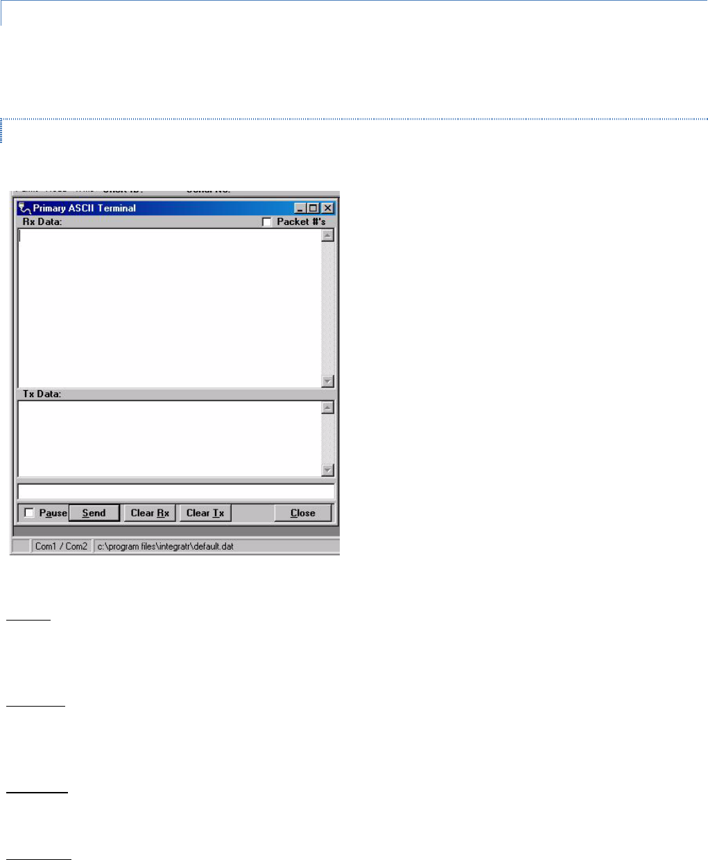
Integra-TR User Manual Page | 63
3.4.21 ASCII / HEX TERMINAL
The ASCII Terminal Screens are accessed from the Utilities pull-down menu and allow the user to select an ASCII,
Hexadecimal TCP Socket or UDP Socket Terminal Screen for the Primary and Secondary COM Ports (configured in the Port
Settings screen - see Section 3.4.10) Data is sent according to the port configuration set up in the Port Settings screen.
3.4.21.1 ASCII TERMINAL
Figure 40 - ASCII Terminal Screen
ASCII Terminal (see Figure 40) configurations include:
Primary
The Primary ASCII Terminal screen allows the user to send and receive ASCII data on the Primary COM Port (setup in the
Port Settings screen).
Secondary
The Secondary ASCII Terminal screen allows the user to send and receive ASCII data on the Secondary COM Port (set up in
the Port Settings screen).
TCP Socket
The TCP Socket Terminal screen allows the user to send and receive ASCII data over a TCP connection.
UDP Socket
The UDP Socket Terminal screen allows the user to send and receive ASCII data over a UDP connection.
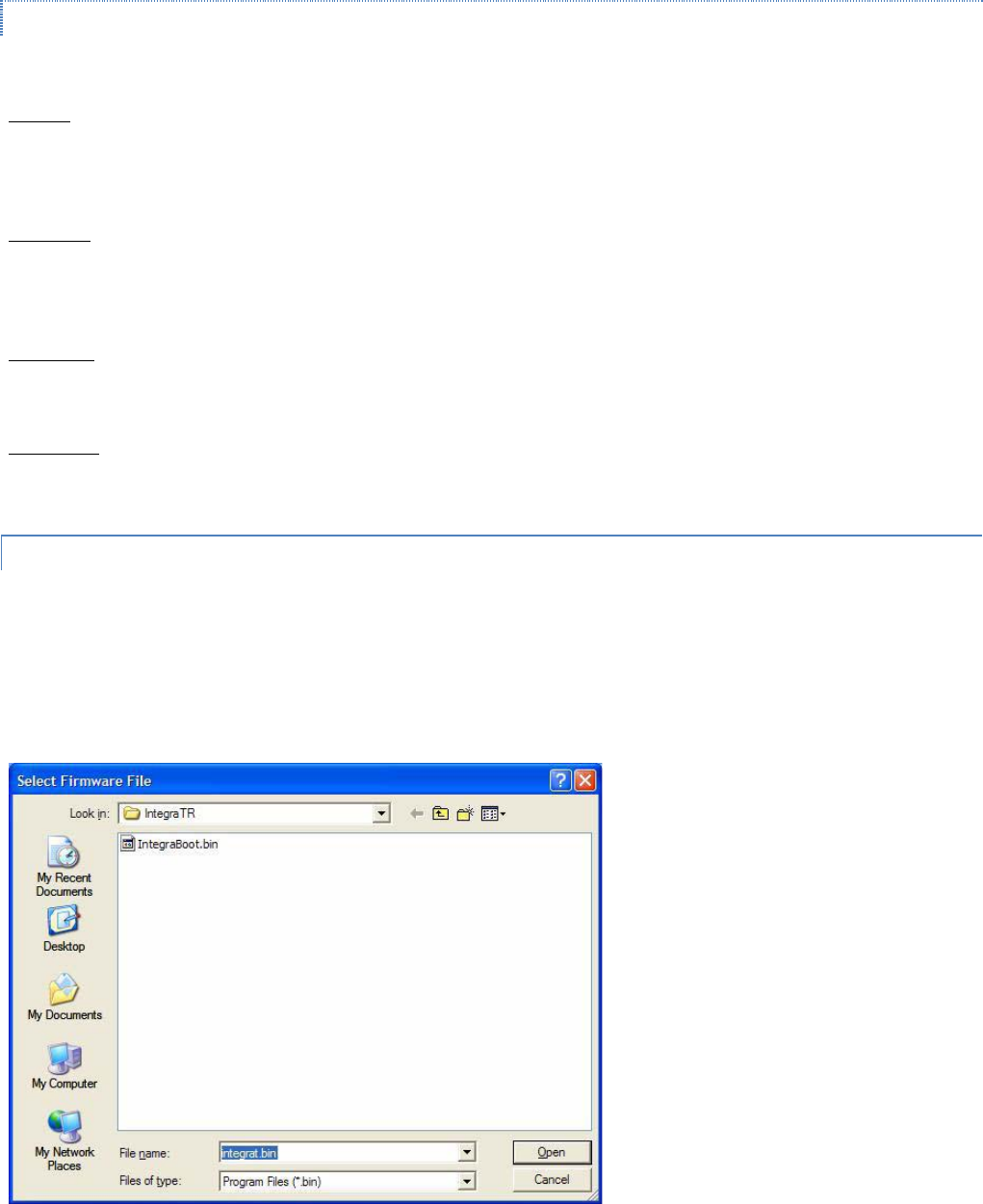
Integra-TR User Manual Page | 64
3.4.21.2 HEX TERMINAL
Hex Terminal configurations include:
Primary
The Primary Hex Terminal screen selects a Hexadecimal Terminal screen to send and receive Hexadecimal data on the
Primary COM Port (set up in the Port Settings screen).
Secondary
The Secondary Hex Terminal screen selects a Hexadecimal Terminal screen to send and receive Hexadecimal data on the
Secondary COM Port (set up in the Port Settings screen).
TCP Socket
The TCP Socket Terminal screen allows the user to send and receive Hexadecimal data over a TCP connection.
UDP Socket
The UDP Socket Terminal screen allows the user to send and receive Hexadecimal data over a UDP connection.
3.4.22 PROGRAM CODE MENU
The Program Code pull-down menu allows the user to update the Integra-TR firmware (*.bin) with the Program Firmware
option, read Boot Code version, select Firmware File (allows the user to select the file to program the firmware in the
Integra-TR) or upgrade the Boot Code file. Selecting one of these options opens a standard navigation window to select the
desired file.
Figure 41 - Select Firmware File Window (for reference only)
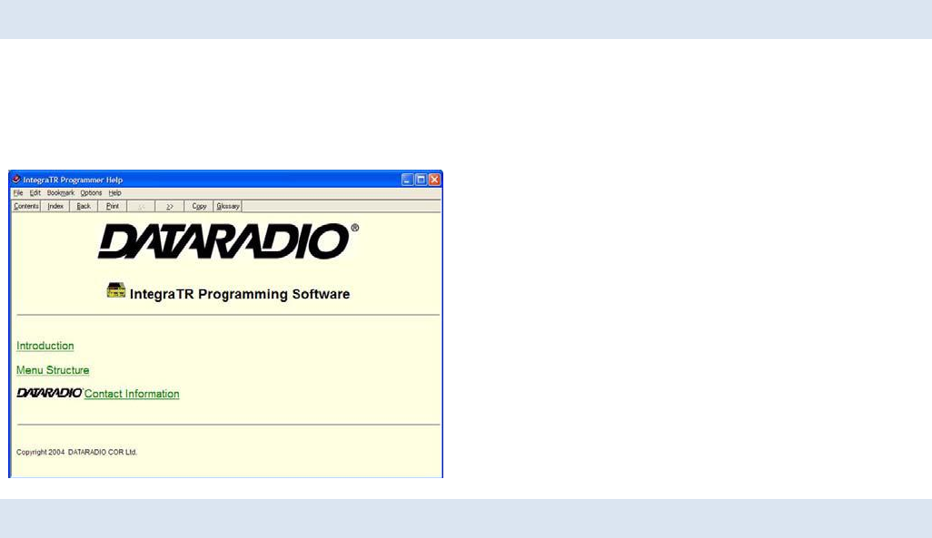
Integra-TR User Manual Page | 65
3.5 INTEGRA-TR HELP FILES
Integra-TR Field Programming Software’s online help files are accessed by the menu bar at the top of the Field
Programming window.
Figure 42 - Integra-TR Online Help Introductory Screen
3.6 OPTIMIZING YOUR SYSTEM
Detailed system engineering is beyond the scope of this manual. However, there are some simple tips that can be used to
optimize performance of a radio based SCADA or telemetry system.
Choose the best protocol Some SCADA devices allow a choice of more than one operating protocol. In some cases,
performance can be improved by selecting a different protocol. Contact Technical Service for assistance.
Check timer settings Polling protocols issue a poll and wait a certain time for a response. Integra-TR adds a short amount of
delay to each poll and response (typically in the order of 60 to 70 ms). Timer settings that are too short may cause
erroneous indication of missed polls, in which case the application may retry or continue to cycle, ignoring the missed
station. In this case, the response may collide with the next poll, further increasing errors. Setting an adequate timer margin
will avoid problems and maximize performance.
Avoid flow control Set the COM port baud rate to a value less than or equal to the radio network speed (2400, 4800, 9600
or 19200 b/s). In a polling system, this will prevent buffer overflow with possible missed transmissions. If the port baud rate
must be set higher than the radio network speed, you may have to limit message length to prevent possible buffer
overflow. Integra-TR will exert a flow control signal (CTS dropped) if buffers are almost full, but not all DTE honor such
signals.
Use the highest suitable port baud rate (without exceeding the radio network speed) Operating an RTU at 1200 b/s on a
9600 b/s network will increase data transmission delays and reduce system performance.
Evaluate the need for online diagnostics Enabling online diagnostics increases delays by 2.5 to 20 ms (depending on
speed). In critical applications, this extra delay can be eliminated by disabling online diagnostics. Offline Diagnostics
(diagnostics on request) remain available.

Integra-TR User Manual Page | 66
Interpreting RSSI Readings
Typical values of RSSI will be in the range of -110 to -60 dBm (depending on network speed), with higher values (i.e. less
negative values) indicating a stronger signal.
Reliability of data reception depends largely on signal strength. Good design practice calls for a minimum 30 dB “fade
margin”, based on a threshold reception level of -107 dBm (1 uV) at speed of 9600 b/s. Experience indicates that this will
give about 99.5% reliability.
Some representative performance values for 9600 b/s operation are given below. These values assume that the units are
correctly aligned and installed in a quiet location. Environments with high electrical or RF noise levels will require an
increase (less negative) in the numbers shown to achieve a given level of reliability.
-100 dBm Approximately 50% reliability. Fading may cause frequent data loss.
-90 dBm Approximately 90% reliability. Fading will cause occasional data loss.
-80 dBm Approximately 99% reliability. Reasonable tolerance to most fading.
-70 dBm Approximately 99.9% reliability with high tolerance to fading.
If RSSI values drops seasonally the most likely cause is tree foliage which can interfere with radio transmissions during the
spring and summer.
Interpreting Power Readings
The values returned are approximate and should not be regarded as an absolute indicator of performance. For example, a
unit that shows a forward power of 4.5 watts may actually measure at 5.0 watts on a lab quality wattmeter. For this reason,
these values should not be used to indicate that a unit is out of spec or to compare one unit to another.
However, the values returned should be consistent for any given unit. If statistics are kept on a unit per unit basis, changes
in forward or reflected power are significant. The following conditions are worthy of investigation.
1. Forward power output (in watts) drops or rises by more than 10% from its established value. Reflected power
remains low. This indicates that the transmitter may need alignment or that a component may be in need of
replacement.
2. Forward power output drops by more than 10% from its established value or reflected power shows an increase.
This indicates a possible antenna or feedline problem that affects SWR (Standing Wave Ratio).
Reverse Power and SWR
A reverse power reading above zero is an indication that the antenna, feedline or connectors are damaged, corroded or
improperly tuned. This creates standing waves that are reported as a Standing Wave Ratio (SWR). Table 10 is based on a
forward power of 5 watts (it may be scaled for lower power settings) and gives guidelines to interpreting these figures:
Table 10 - SWR / Rev Pwr Interpretation
SWR
Rev Pwr
Significance
1:1
0
Ideal situation
1.5:1
0.2
Normal operation
2:1
0.6
Should be investigated
3:1 or greater
1.25 or greater
Defective antenna, feedline, or connectors
Should values returned by the built-in diagnostics seem to indicate a problem, verify using proper radio shop equipment.

Integra-TR User Manual Page | 67
4 CONFIGURABLE PARAMETERS
4.1 PARAMETER OVERVIEW
The parameters used to configure the Integra-TR units are described in the Field Programming Software help file. Section 4
summarizes the Integra-TR parameter settings and their variations when used within a network.
Table 11 - Normal Factory Settings (Units)
Fields
Integra-TR with other Integra-TR
Integra-T / TR
Integra-T
Network Settings
Compatibility Mode
Integra-TR
Integra-T / TR
(N/A)
Tx/Rx Mode
Both Tx and Rx
(N/A)
Extended Preamble (ms)
5 mS
0 mS
0 mS
Network Speed
19200 Full Channel
9600 Half Channel
2400 Quarter Channel
9600 Full Channel
Tx Online Diagnostics
Yes
Unit Type
Master
Data Delivery
All
Suspend Period (ms)
0
Activity Time-out (sec)
5
Sleep Mode
Disable (N/A)
COM Port
Device Baud
19200
9600
Data fwd timer
Normal
Parity
8 bit, no parity, 1 stop bit
Break
Ignore break
Xmit Control
DOX
DCD Control
Switched
External I/O Connector
I/O 1
Input or Fan Control (units with cooling fan option) Digital Output
(units not equipped with cooling fan option when Modem Board
Rev is 0 or 1)
Input
I/O 2
Input Digital Output to control open-collector transistor (when Modem Board Rev is 0 or
1)
Frequency
Transmit
User choice
Receive
User choice
Adjustments
Carrier Sense (-dBm)
105 (116 for quarter-channel)
110
Tx Time Out
30 sec ON
Disable Tx w/ Carrier Present
Disabled (OFF)
Power Out
255 (indicates 5 Watts nominal)
Transceiver Type
Transceiver
Refer to help files (See section 3.5) for descriptions of the above fields.

Integra-TR User Manual Page | 68
Table 12 - Normal Factory Settings (Bases)
Fields
Full Duplex Base Integra-TR with other
Integra-TR
Redundant Integra-TR Full Duplex
Base with Integra-TR/Integra-T
RX Unit
TX Unit
RX Units
TX Units
Network Settings
Station ID (CWID)
Disabled (OFF)
Compatibility Mode
Integra-TR
Integra-T / TR
Extended Preamble (ms)
5 mS
0 mS
Network Speed
19200 Full Channel 9600 Half Channel
2400 Quarter Channel
9600 Full Channel
Tx Online Diagnostics
Yes
Unit Type
Master
Data Delivery
All
Activity Time-out (sec)
5
COM Port
Device Baud
19200 / 9600 / 2400
9600
Data fwd timer
Normal
Parity
8 bit, no parity, 1 stop bit
Break
Ignore break
Xmit Control
DOX
DCD Control
Switched
External I/O Connector
I/O 1
Input Output
Fan Control
Input Output
Fan Control
I/O 2
RxTp
Input
RxTp
Ant. SW Control
Frequency
Transmit
User Choice
Receive
User Choice
Adjustments
Carrier Sense (-dBm)
105 (116 for
quarter-channel)
(N/A)
110
(N/A)
Tx Time Out
Disabled
Disable Tx w/Carrier Present
Disabled (OFF)
Tx Power
255 (indicates 5 watts nominal)
Transceiver Type
Rx Only
Tx Only
Rx Only
Tx Only
Refer to help files (See section 3.5) for descriptions of the above fields.

Integra-TR User Manual Page | 69
5 DEFINITIONS
Bit dribble Extraneous bits delivered at the end of a data transmission. Equivalent to a “squelch tail” in voice
systems. Integra-TR does not have bit dribble.
COM Port The Communications Port of Integra-TR. This port is configured as DCE and is designed to connect
directly to DTE.
CTS Clear to Send. An RS-232 output signal from Integra-TR indicating that it is ready to accept data (used
in RTS mode).
DCE Data Communications Equipment. This designation is applied to equipment such as modems. DCE is
designed to connect to DTE.
DOX Data Operated Transmit. A mode of operation in which Integra-TR begins a transmission as soon as
data is presented to the RS-232 port.
DTE Data Terminal Equipment. This designation is applied to equipment such as terminals, PCs, RTUs, PLCs,
etc. DTE is designed to connect to DCE.
Field Programming
Software This software allows configuration and testing of Integra-TR
Full Channel Radio channel bandwidth equal to 25kHz.
Half Channel Radio channel bandwidth equal to 12.5kHz.
Multi-Channel The Integra-TR has multi-channel capability under system PLC control for advanced network
monitoring .
Network speed This is the bit rate on the RF link between units. Could be different from COM port baud rate.
PLC Programmable Logic Controller. An intelligent device that can make decisions, gather and report
information, and control other devices.
Refarming Strategy for using the radio spectrum more efficiently to meet future communications requirements
and the FCC's minimum bit rate requirements with speeds up to 19200 in Full Channel and 9600 in
Half Channel.
RTS Request to Send. RS-232 input signal to Integra-TR indicating that the DTE has data to send. RTS may
optionally be used as a transmit switch for Integra-TR.
RTS mode A mode of operation in which Integra-TR begins a transmission when RTS is raised and continues
transmitting until RTS is dropped.
RTU Remote Terminal Unit. A SCADA device used to gather information or control other devices.
SCADA Supervisory Control And Data Acquisition. A general term referring to systems that gather data and/or
perform control operations.
Setup Port The configuration / diagnostic port of Integra-TR. This port is designed to be connected to a PC
running the Integra Field Programming Software.
Transparent A transparent unit transmits all data without regard to special characters, etc.

Integra-TR User Manual Page | 70
ABOUT CALAMP
CalAmp is a leading provider of wireless communications products that enable anytime/anywhere access to critical
information, data and entertainment content. With comprehensive capabilities ranging from product design and
development through volume production, CalAmp delivers cost-effective high quality solutions to a broad array of
customers and end markets. CalAmp is the leading supplier of Direct Broadcast Satellite (DBS) outdoor customer premise
equipment to the U.S. satellite television market. The Company also provides wireless data communication solutions for the
