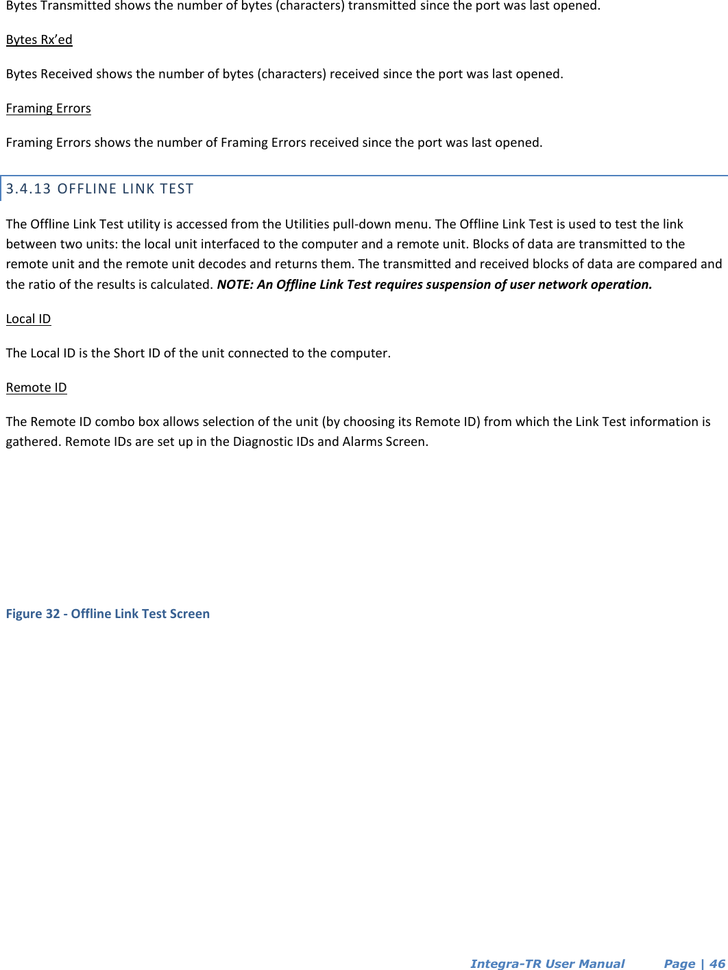
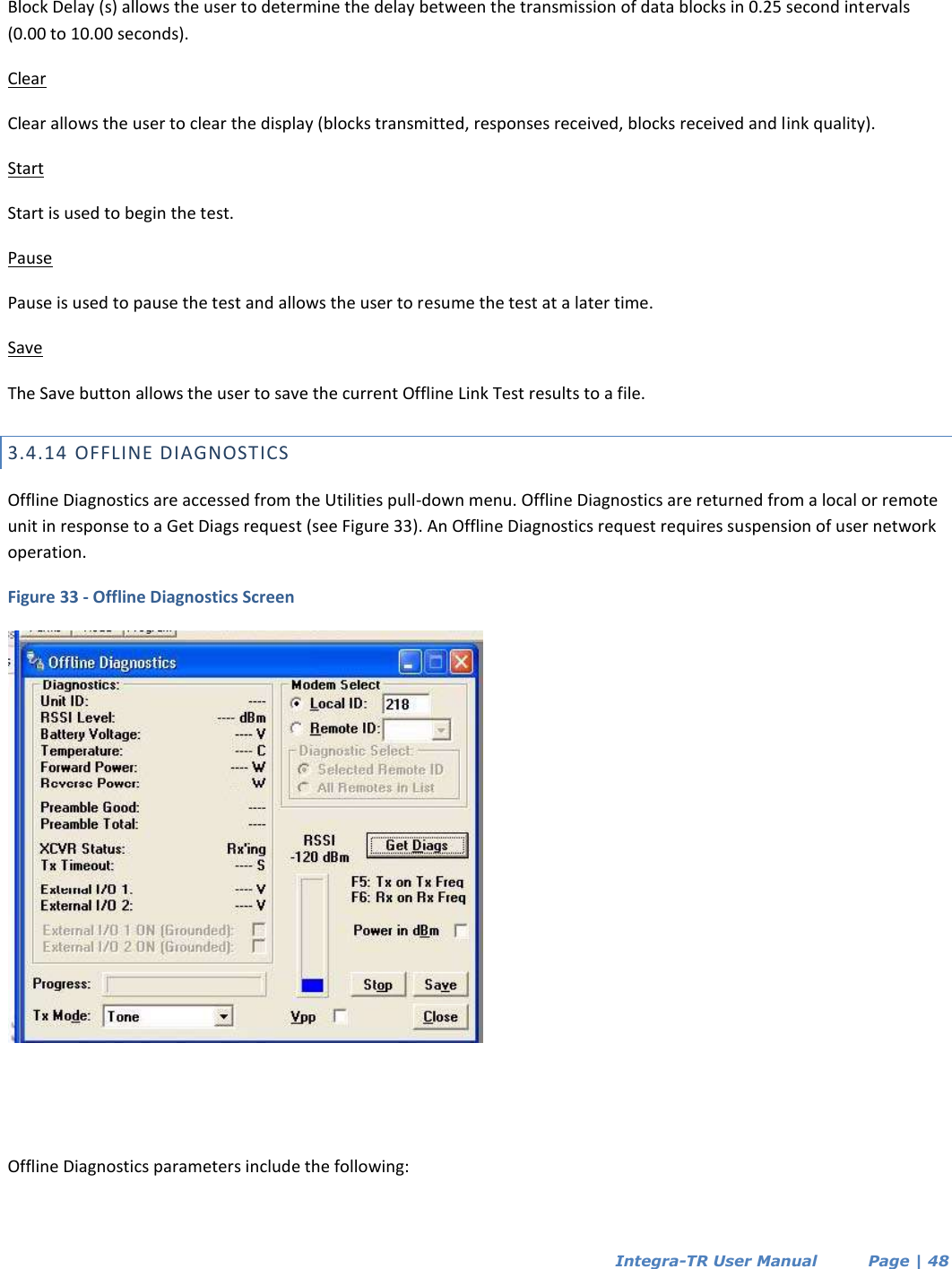
CalAmp Wireless Networks 4048350 Integra UHF Wireless Radio Modem User Manual Manual
CalAmp Wireless Networks Corporation Integra UHF Wireless Radio Modem Manual
UserManual.wiki
>
CalAmp Wireless Networks
>
4048350 User Manual
Manual
Navigation menu
Upload a User Manual
Namespaces
Wiki Guide
HTML
PDF
Info
Views
User Manual
Discussion / Help
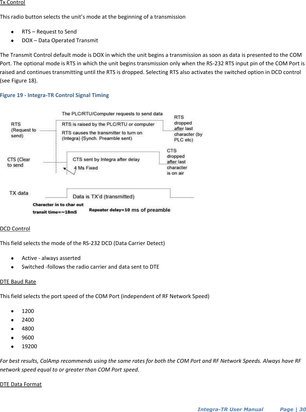
Navigation