CalAmp Wireless Networks 5026-500 Guardian 200 Wireless Radio Modem User Manual
CalAmp Wireless Networks Corporation Guardian 200 Wireless Radio Modem
User Manual
GUARDIAN™
HIGHSPECRADIOMODEM
UserManual
PN001‐5006‐000Rev0
RevisedFebruary2010

REVISION HISTORY
REVDATEREVISIONDETAILS
0February25,2010InitialReleaseas001‐5006‐000.

IMPORTANTNOTICE
Becauseofthenatureofwirelesscommunication,transmissionandreceptionofdatacanneverbeguaranteed.Data
maybedelayed,corrupted(i.e.,haveerrors),orbetotallylost.Significantdelaysorlossesofdataarerarewhen
wirelessdevicessuchastheGuardianareusedinanormalmannerwithawell‐constructednetwork.Guardianshould
notbeusedinsituationswherefailuretotransmitorreceivedatacouldresultindamageofanykindtotheuserorany
otherparty,includingbutnotlimitedtopersonalinjury,death,orlossofproperty.CalAmpacceptsnoresponsibilityfor
damagesofanykindresultingfromdelaysorerrorsindatatransmittedorreceivedusingGuardian,orforthefailureof
Guardiantotransmitorreceivesuchdata.
COPYRIGHTNOTICE
©Copyright2007CalAmp.
ProductsofferedmaycontainsoftwareproprietarytoCalAmp.Theofferofsupplyoftheseproductsandservicesdoes
notincludeorinferanytransferofownership.Nopartofthedocumentationorinformationsuppliedmaybedivulged
toanythirdpartywithouttheexpresswrittenconsentofCalAmp.
RF EXPOSURE COMPLIANCE REQUIREMENTS
TheGuardianradioisintendedforuseintheIndustrialMonitoringandControlandSCADAmarkets.TheGuardianunit
mustbeprofessionallyinstalledandmustensureaminimumseparationdistancelistedinthetablebelowbetweenthe
radiatingstructureandanyperson.Anantennamountedonapoleortoweristhetypicalinstallationandinrare
instances,a1/2‐wavewhipantennaisused.
Antenna Gain
5 dBi 10 dBi 15 dBi
Min Safety Distance
(VHF @ max Power) 123cm 218.8cm 389cm
Min Safety Distance
(UHF @ max Power) 105.7cm 188cm 334.4cm
Min Safety Distance
(900 MHz @ max power) 63.8cm 115 cm 201.7 cm
Note:ItistheresponsibilityoftheusertoguaranteecompliancewiththeFCCMPEregulationswhenoperatingthis
deviceinawayotherthandescribedabove.
TheGuardianradiousesalowpowerradiofrequencytransmitter.Theconcentratedenergyfromanantennamaypose
ahealthhazard.Peopleshouldnotbeinfrontoftheantennawhenthetransmitterisoperating.
TheinstallerofthisequipmentmustensuretheantennaislocatedorpointedsuchthatitdoesnotemitanRFfieldin
excessofHealthCanadalimitsforthegeneralpopulation.Recommendedsafetyguidelinesforthehumanexposureto
radiofrequencyelectromagneticenergyarecontainedintheCanadianSafetyCode6(availablefromHealthCanada)
andtheFederalCommunicationsCommission(FCC)Bulletin65.
Anychangesormodificationsnotexpresslyapprovedbythepartyresponsibleforcompliance(inthecountrywhere
used)couldvoidtheuser'sauthoritytooperatetheequipment.
RF E

REGULATORYCERTIFICATIONS
TheGuardianradioisavailableinseveraldifferentmodelseachwithuniquefrequencybands.EachmodelofGuardian
mayhavedifferentregulatoryapprovalasshowninthetablebelow.
ULCertification
AllmodelsULapprovedwhenpoweredwithalistedClass2source.
DECLARATION OF CONFORMITY FOR MODEL # 140-5046-400
Thisdevice(Guardianmodel#140‐5046‐400)isadatatransceiverintendedforcommercialandindustrialuseinallEU
andEFTAmemberstates.
Česky [Czech] CalAmptímtoprohlašuje,žetentorádio
j
eveshoděsezákladnímipožadavkyadalšími
příslušnýmiustanovenímisměrnice1999/5/ES.
Dansk [Danish] UndertegnedeCalAmp erklærerherved,atfølgendeudstyrradiooverholderde
væsentligekravogøvrigerelevantekravidirektiv1999/5/EF.
Deutsch [German] HiermiterklärtCalAmp,dasssichdasGerätradioinÜbereinstimmungmitden
grundlegendenAnforderungenunddenübrigeneinschlägigenBestimmungender
Richtlinie1999/5/EGbefindet.
Eesti [Estonian] KäesolevagakinnitabCalAmp seadme raadio vastavustdirektiivi1999/5/EÜpõhinõuetele
janimetatuddirektiivisttulenevateleteisteleasjakohastelesätetele.
English Hereby,CalAmp, declaresthatthisradio isincompliancewiththeessentialrequirements
andotherrelevantprovisionsofDirective1999/5/EC.
Español [Spanish] PormediodelapresenteCalAmp declaraqueelradio cumpleconlosrequisitos
esencialesycualesquieraotrasdisposicionesaplicablesoexigiblesdelaDirectiva
1999/5/CE.
Ελληνική [Greek] ΜΕΤΗΝΠΑΡΟΥΣΑ CalAmp ΔΗΛΩΝΕΙΟΤΙΡΑΔΙΌΦΩΝΟ ΣΥΜΜΟΡΦΩΝΕΤΑΙΠΡΟΣΤΙΣ
ΟΥΣΙΩΔΕΙΣΑΠΑΙΤΗΣΕΙΣΚΑΙΤΙΣΛΟΙΠΕΣΣΧΕΤΙΚΕΣΔΙΑΤΑΞΕΙΣΤΗΣΟΔΗΓΙΑΣ1999/5/ΕΚ.
Français [French] ParlaprésenteCalAmp déclarequel'appareilradio estconformeauxexigences
essentiellesetauxautresdispositionspertinentesdeladirective1999/5/CE.
Italiano [Italian] ConlapresenteCalAmp dichiarachequestoradio èconformeairequisitiessenzialiedalle
altredisposizionipertinentistabilitedalladirettiva1999/5/CE.
Latviski [Latvian] AršoCalAmp deklarē,karadio atbilstDirektīvas1999/5/EKbūtiskajāmprasībāmuncitiem
artosaistītajiemnoteikumiem.
Lietuvių ŠiuoCalAmp deklaruoja,kadšis radijo atitinkaesminiusreikalavimusirkitas1999/5/EB
Certifications
Model Number Frequency Range FCC IC(DOC)EuropeanUnion
EN300113
Australia/NewZealand
140-5016-500 136 – 174 MHz NP4-5016-500 773B-5016500
140-5016-501 136 – 174 MHz NP4-5016-500 773B-5016500
140-5026-500 216 – 222 MHz NP4-5026-500 773B-5026500
140-5026-501 216 – 222 MHz NP4-5026-500 773B-5026500
140-5046-300 406 - 470 MHz NP4-5046-500 773B-5046500
140-5046-301 406 - 470 MHz NP4-5046-500 773B-5046500
140-5046-500 450 - 512 MHz NP4-5046-500 773B-5046500
140-5046-501 450 - 512 MHz NP4-5046-500 773B-5046500
140-5096-500 928 - 960 MHz NP4-5096-500 773B-5096500
140-5096-501 928 - 960 MHz NP4-5096-500 773B-5096500

[Lithuanian] Direktyvosnuostatas.
Nederlands
[Dutch]
HierbijverklaartCalAmp dathettoestel radio inovereenstemmingismetdeessentiële
eisenendeandererelevantebepalingenvanrichtlijn1999/5/EG.
Malti [Maltese] Hawnhekk,CalAmp ,
j
iddikjaralidantar‐radju
j
ikkonformamal‐
ħ
tiġijietessenzjaliuma
provvedimentioħrajnrelevantilihemmfid‐Dirrettiva1999/5/EC.
Magyar
[Hungarian]
Alulírott,CalAmp nyilatkozom,hogyarádió megfelelavonatkozóalapvetõ
követelményeknekésaz1999/5/ECirányelvegyébelõírásainak.
Polski [Polish] NiniejszymCalAmp oświadcza,żeradio
j
estzgodnyzzasadniczymiwymogamioraz
pozostałymistosownymipostanowieniamiDyrektywy1999/5/EC.
Português
[Portuguese]
CalAmpdeclaraqueesterádio estáconformecomosrequisitosessenciaiseoutras
disposiçõesdaDirectiva1999/5/CE.
Slovensko
[Slovenian]
CalAmpizjavlja,dajetaradio vskladuzbistvenimizahtevamiinostalimirelevantnimi
določilidirektive1999/5/ES.
Slovensky
[Slovak]
CalAmptýmtovyhlasuje,žerádiospĺňazákladnépožiadavkyavšetkypríslušné
ustanoveniaSmernice1999/5/ES.
Suomi [Finnish] CalAmpvakuuttaatätenettäradio tyyppinenlaiteondirektiivin1999/5/EYoleellisten
vaatimustenjasitäkoskeviendirektiivinmuidenehtojenmukainen.
Svenska
[Swedish]
HärmedintygarCalAmp attdennaradio stårIöverensstämmelsemeddeväsentliga
egenskapskravochövrigarelevantabestämmelsersomframgåravdirektiv1999/5/EG.
Íslenska [Icelandic] HérmeðlýsirCalAmp yfirþvíað útvarp erísamræmiviðgrunnkröfurogaðrarkröfur,sem
gerðareruítilskipun1999/5/EC.
Norsk
[Norwegian]
CalAmperklærerhervedatutstyretradio erisamsvarmeddegrunnleggendekravog
øvrigerelevantekravidirektiv1999/5/EF.
TABLE OF CONTENTS
1
1GUARDIAN OVERVIEW ........................................................................................................................................... 9
1.1General Description ............................................................................................................................................ 9
1.2Operational Characteristics ............................................................................................................................... 9
1.3Physical Description ......................................................................................................................................... 10
1.3.1Front Panel .................................................................................................................................................. 10
1.3.2LED Panel ................................................................................................................................................... 11
1.3.3User Interface Port ...................................................................................................................................... 11
1.3.4SETUP and COM Ports .............................................................................................................................. 11
1.3.5Power Connector ........................................................................................................................................ 12
1.3.6Antenna Connector ..................................................................................................................................... 13
1.3.7Chassis Dimensions .................................................................................................................................... 13
1.4Part Numbers and Availability ........................................................................................................................ 14
1.4.1Guardian Radio ........................................................................................................................................... 14
1.4.2Accessories and Options ............................................................................................................................. 14
1.5Product Warranty ............................................................................................................................................ 15
1.6RMA Request .................................................................................................................................................... 16
1.7Documentation and Downloads ....................................................................................................................... 16
2SYSTEM ARCHITECTURE AND NETWORK PLANNING ................................................................................. 17
2.1Single Coverage Area ....................................................................................................................................... 17
2.2Network Architecture ....................................................................................................................................... 17
2.2.1Point-to-Point .............................................................................................................................................. 17
2.2.2Point-to-Multipoint ..................................................................................................................................... 18
2.2.3Multiple Point-to-Point ............................................................................................................................... 18
2.2.4Peer-to-Peer ................................................................................................................................................ 18
2.2.5Store and Forward ....................................................................................................................................... 18
2.2.6Network Using a T-Base ............................................................................................................................. 19
2.2.7Network Using a T-Base Repeater ............................................................................................................. 19
2.2.8Network Using a Guardian for Online Diagnostics .................................................................................... 19
2.3Extending the Coverage Area with a Relay Point .......................................................................................... 20
2.3.1Understanding RF Path Requirements ........................................................................................................ 20
2.4Site Selection and Site Survey .......................................................................................................................... 21
2.4.1Site Selection .............................................................................................................................................. 21
2.4.2Site Survey .................................................................................................................................................. 21
2.5Selecting Antenna and Feedline ....................................................................................................................... 21
2.5.1Antenna Gain .............................................................................................................................................. 21
2.5.2Omni Directional Antenna .......................................................................................................................... 22
2.5.3Yagi Antenna .............................................................................................................................................. 22
2.5.4Vertical Dipoles .......................................................................................................................................... 22
2.5.5Feedline ...................................................................................................................................................... 23
2.5.6RF Exposure Compliance Requirements .................................................................................................... 23
2.6Terrain and Signal Strength ............................................................................................................................ 24
2.7Radio Interference ............................................................................................................................................ 24
3SETUP AND CONFIGURATION ............................................................................................................................ 26
3.1Install the Antenna ........................................................................................................................................... 26
3.2Measure and Connect Primary Power ............................................................................................................ 26
3.3Connect Guardian to Programming PC ......................................................................................................... 26
3.4Guardian Field Programming Software ......................................................................................................... 26
4UNIT STATUS ........................................................................................................................................................... 27
4.1Unit Identification and Status .......................................................................................................................... 27
4.2Diagnostics ......................................................................................................................................................... 27
4.2.1Online Diagnostics ...................................................................................................................................... 27
4.2.2Offline Diagnostics ..................................................................................................................................... 28
4.2.3Remote Commands ..................................................................................................................................... 28
5GUARDIAN FIELD PROGRAMMING SOFTWARE ............................................................................................ 29
5.1Introduction ...................................................................................................................................................... 29
5.1.1COM Port Settings ...................................................................................................................................... 29
5.1.2COM Port Parameters ................................................................................................................................. 29
5.1.3Port Statistics .............................................................................................................................................. 31
5.1.4Setup Modem/Radio Parameters ................................................................................................................. 32
5.1.5Version Request .......................................................................................................................................... 41
5.1.6Writing/Reading Guardian Parameters ....................................................................................................... 41
5.1.7Clone Programmable Parameters ................................................................................................................ 41
5.1.8Diagnostic IDs and Alarms ......................................................................................................................... 42
5.1.9Offline Link Test ........................................................................................................................................ 43
5.1.10Offline Diagnostics ..................................................................................................................................... 45
5.1.11Online Diagnostics ...................................................................................................................................... 48
5.1.12User Test ..................................................................................................................................................... 51
5.1.13Packet Test .................................................................................................................................................. 52
5.1.14Array Test ................................................................................................................................................... 54
5.1.15ASCII / HEX Terminal ............................................................................................................................... 57
5.1.16Program Code ............................................................................................................................................. 58
5.1.17End to End Test .......................................................................................................................................... 58
6GUARDIAN SPECIFICATIONS ............................................................................................................................. 62
7PRODUCT WARRANTY .......................................................................................................................................... 66

GuardianManual001‐5006‐000Rev09|Page
1
1
GUARDIANOVERVIEW
ThisdocumentprovidesinformationrequiredfortheoperationandverificationoftheCalAmpGuardian
NarrowbandModem.
1.1 GENERALDESCRIPTION
ThisDSP‐basedradiowasdesignedforSCADA,telemetryandindustrialapplicationsinthe136‐174MHz,215‐240
MHzVHF,406.1‐512MHzUHF,and928‐960MHzfrequencyranges.
GuardiansupportsserialRemoteTerminalUnits(RTU)andprogrammablelogiccontrollers(PLC).TheGuardianis
compatiblewithanyDataradioInteroperabilityStandard(DI‐OS)equipmentandBell202/212interface.
1.2 OPERATIONALCHARACTERISTICS
TheGuardianproducthasthefollowingoperationalcharacteristics:
Frequencyrangeof136‐174MHz,215‐240MHz,406.1‐470MHz,450‐512MHz,or928‐960MHz.
User‐selectabledatarates
Built‐intransceiveradjustablefrom1to10watts(8wattsmaxfor900MHz)
Wideinputpowerrangeof10to30voltsDC
OnlineandOfflineDiagnostics
Supportsupto8differentfrequencychannelpairs(selectablethroughuserinterfaceport).
Industrialoperatingtemperaturerangeof‐30to+60C
Ruggeddie‐castaluminumandsteelcase

GuardianManual001‐5006‐000Rev010|Page
Thesefeaturesprovidesystembenefitsthatgiveusers:
RuggedPackaging.Guardianishousedinacompactandruggedcastaluminumcase.Builtforindustrial
applicationsinavarietyofenvironments,Guardianoperatesoveranextendedtemperaturerangeandprovides
worry‐freeoperationintheroughestenvironments.
SimpleInstallation.Basicinstallationtypicallyutilizesanomni‐directionalantennaatthemasterstationorRelay
PointandadirectionalantennaateachremotesitenotaRelayPoint.SeeSection2forinformationonSiteand
AntennaSelection.Forbasicservice,justhookupanantenna,applyprimarypower,checkandsetafewoperating
parametersandyouaredone.
FlexibleManagement.Configuration,commissioning,maintenanceandtroubleshootingcanbedonelocallyor
remotely.Therearenophysicalswitchesoradjustments.TheDual‐PortGuardianprovidesareceiveantenna
connectorallowingforuniquecustomerapplicationsrequiringadditionalreceivefiltering,externalPA(s),and
otheroptions.
LongRange.Narrowbandconfigurationsallowbettercoverageoverharshterrain.
1.3 PHYSICALDESCRIPTION
GuardianconsistsoftwologicPCBs,onethatincludesthemodemcircuitryandtheothertheradiomodule.Both
areinstalledinacastaluminumcase.Theunitisnothermeticallysealedandshouldbemountedinasuitable
enclosurewhendust,moisture,and/oracorrosiveatmosphereareanticipated.
TheGuardianisdesignedforeasyinstallationandconfiguration;theGuardianfeaturesnoexternalorinternal
switchesoradjustments.Alloperatingparametersaresetviathesetupport.
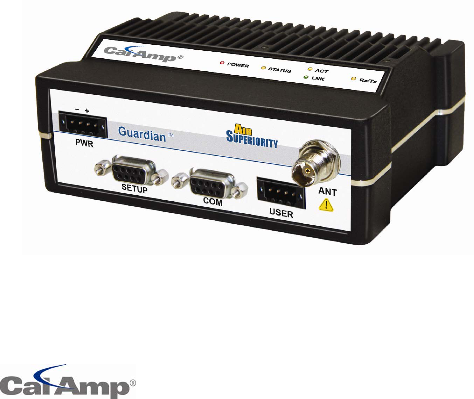
1.3.1 FRONTPANEL
Thefrontpanelhasthefollowingconnections:
(1)8‐Pinuserinterfaceblockconnector
(1)50‐ohmTNCfemaleAntennaconnector
(1)50‐ohmSMAfemalereceiveantennaconnector(Dual‐Portmodelsonly)
(1)Right‐anglepowerconnector(10‐30VDC)
(2)DE‐9FRS‐232ports
ForDual‐portGuardianconnections,seeSection1.3.6.

GuardianManual001‐5006‐000Rev011|Page
1.3.2 LEDPANEL
TheLEDpanelhasfiveTri‐ColorLEDs.ThefunctionalityofeachLEDisshowninTable1.1.
Table1.1GuardianLEDFunctionality
LEDColorDefinition
PowerGreen
Amber(SolidorBlinking)
Red
Guardian ready,normaloperations
GuardianisProgramming
Guardianhardwarefault
StatusGreen
Red
Amber(SolidorBlinking)
Guardian nofaults,normaloperations
Guardianhasafaultcondition,checkunitstatus
Guardiandetectshighbackgroundnoise
Rx
Green
Off
Receivingdata
TxRed
BlinkingAmber
Off
Transmittingdata
Theunitwantstotransmit,butisinhibited.
Rd/TdGreen
Red
Receive data isbeingsentoutoftheport
Transmitdataisbeingreceivedbytheport
1.3.3 USERINTERFACEPORT
Theuserinterfaceportisan8pinblockreceptacle,programmabletoworkwith1.8Vto5Vlevels.Table1.2shows
pin‐outdescriptionsfortheRJ‐45port.
Table1.2Pin‐outforUserInterfacePortContacts
Contact10Base‐TSignal
1TxAudioIn
2RxAudioOut
3PTT
4RSSIOut
5Ground
6ChannelSelect1
7ChannelSelect2
8ChannelSelect3
1.3.4 SETUPANDCOMPORTS
TheSETUPandCOMserialconnectionsareDE‐9FRS‐232ports.
Serialportconsiderations:

GuardianManual001‐5006‐000Rev012|Page
• GuardianradiomodemSETUPandCOMportsareDataCommunicationEquipment(DCE)devices
• Ingeneral,equipmentconnectedtotheGuardian’sSETUP/COMserialportisDataTerminalEquipment
(DTE)andastraight‐throughcableisrecommended.
Note:IfaDCEdeviceisconnectedtotheGuardianSETUP/COMport,anullmodemcable/adapteris
required.
Thepin‐outfortheSETUPandCOMportsareshowninTable1.3.
Table1.3Pin‐outforDCESETUPandCOMport,9ContactDE‐9Connector
ContactEIA‐232FFunction SignalDirection
1DCD(1) DTE←DCE
2RXD DTE←DCE
3TXD DTE→DCE
4DTR DTE→DCE
5GND DTE‐‐‐DCE
6DSR(2) DTE←DCE
7RTS(1) DTE→DCE
8CTS(1) DTE←DCE
9RING(3) DTE ‐‐‐ DCE
(1)Programmable.
(2)Alwaysasserted
(3)Forfutureuse
TheDCD,DTR,RTSandCTScontrollinesareprogrammable.Refertosection6.4forserialportcontrolline
configurations.
1.3.5 POWERCONNECTOR
TheGuardianissuppliedwitharight‐anglepowerconnector(10‐30VDC).Table1.4showsthepin‐outofthe
powerconnector.
Table1.4Pin‐outofthepowerconnector
Contact#
(LefttoRight)
Color Description
4FanPowerOutput(5V)
3Black Ground
2Red Positive(10‐30)VDC
1White Enable
Note:TheWhiteEnablelinemustbetiedtotheredpositiveleadoftheconnectorfortheGuardiantofunction.
GuardianManual001‐5006‐000Rev013|Page
1.3.6 ANTENNACONNECTOR
ThestandardGuardianhasa50‐ohmTNCfemaleantennaconnector.Thisconnectionfunctionsforbothtransmit
andreceive.
TheDual‐PortGuardianhasa50‐ohmTNCfemaleantennaconnectorfunctioningfortransmit(only)anda50‐ohm
SMAfemaleantennaconnectorfunctioningforreceive(only).Theseparatereceiveantennaconnectorallowsfor
uniquecustomerapplicationsthatrequireadditionalreceivefiltering,externalPA(s)andotheroptions.
Warning:ThetransmitantennaportmustnotbeconnecteddirectlytothereceiveantennaportoftheDual‐Port
Guardian.Excessivepowerintothereceiveantennaportwilldamagetheradio.Inputpowertothereceiver
shouldnotexceed17dBm(50mW).
Toreducepotentialinterference,theantennatypeanditsgainshouldbechosentoensuretheeffectiveisotropic
radiatedpower(EIRP)isnotmorethanrequiredforsuccessfulcommunication.
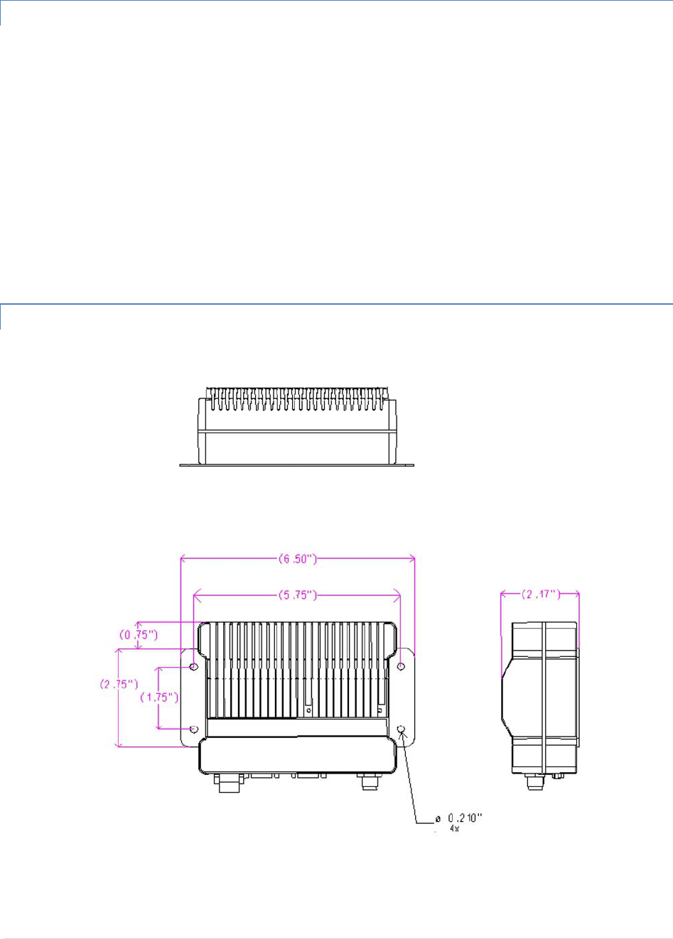
1.3.7 CHASSISDIMENSIONS
Figure1.2showsthedimensionsoftheGuardianChassisandmountingplate.

GuardianManual001‐5006‐000Rev014|Page
1.4 PARTNUMBERSANDAVAILABILITY
1.4.1 GUARDIANRADIO
Table1.5providesabreakdownoftheGuardianpartnumber140‐50X6‐Y0Z.
Table1.5‐PartNumberBreakdown
ModelNumberDescription FrequencyRange
140‐5016‐500StandardVHFGuardian 136‐ 174MHz
140‐5026‐502StandardVHFGuardian‐200 215‐ 240MHz
140‐5046‐300StandardUHFGuardian Range3406.1‐470MHz
140‐5046‐500StandardUHFGuardian Range5450‐ 512MHz
140‐5096‐500Standard900MHzGuardian 928‐ 960MHz
140‐5016‐501DualPortVHFGuardian 136‐ 174MHz
140‐5026‐503DualPortVHFGuardian‐200 215‐ 240MHz
140‐5046‐301DualPortUHFGuardian Range3406.1‐470MHz
140‐5046‐501DualPortUHFGuardian Range5450‐ 512MHz
140‐5096‐501DualPort900MHzGuardian 928‐ 960MHz
1.4.2 ACCESSORIESANDOPTIONS
Tables1.6‐1.8liststandardaccessories(includingantenna,feedline,andconnectors)testedandapprovedforuse
withtheGuardian.
Table1.6‐Accessories
ITEMPARTNUMBER
GuardianPowerCable897‐5008‐010
GuardianDemoKit*
–
VHF‐136‐174MHz 250‐5016‐500
GuardianDemoKit*
–
VHF200‐215‐240MHz 250‐5026‐502
GuardianDemoKit*
–
UHF‐406‐470MHz 250‐5046‐300
GuardianDemoKit*
–
UHF‐450‐512MHz 250‐5046‐500
GuardianDemoKit*
–
900‐928‐960MHz 250‐5096‐500
FactoryInstalledGuardianFanKit150‐5008‐001
FieldInstalledGuardianFanKit**150‐5008‐002
TNC‐MaletoN‐Male18”250‐0697‐103
TNC-Male to N-Male 48” 250‐0697‐104
TNC‐MaletoN‐Male72”250‐0697‐105
TNC‐MaletoN‐Female18”250‐0697‐106
*TheGuardianDemoKitincludestwoofeachofthefollowing:Guardian,rubberduckantennas,adapters,attenuators,powercables,and
powersupplies.
**ThefieldinstallFanKitisavailableforallVHF200/UHF/900Guardians(140‐5026‐XXX/140‐5046‐xxx/140‐5096‐xxx)butisonlyavailablefor
VHFmodels‐(140‐5016‐xxx)withRFrevision0.3orgreater(shippingFall2008).ContactCalAmpTechnicalSupportformoreinformation.

GuardianManual001‐5006‐000Rev015|Page
Table1.7AntennaKits
ITEMPARTNUMBER
AntennaKit*:138‐143MHz6.5dBd250‐0211‐007
AntennaKit*:138‐143MHz9.5dBd250‐0211‐010
AntennaKit*:143‐148MHz6.5dBd250‐0211‐107
AntennaKit*:143‐138MHz9.5dBd250‐0211‐110
AntennaKit*:148‐152MHz6.5dBd250‐0211‐207
AntennaKit*:148‐152MHz9.5dBd250‐0211‐210
AntennaKit*:152‐157MHz6.5dBd250‐0211‐307
AntennaKit*:152‐157MHz9.5dBd250‐0211‐310
AntennaKit*:157‐163MHz6.5dBd250‐0211‐407
AntennaKit*:157‐163MHz9.5dBd250‐0211‐410
AntennaKit*:163‐169MHz6.5dBd250‐0211‐507
AntennaKit*:163‐169MHz9.5dBd250‐0211‐510
AntennaKit*:169‐174MHz6.5dBd250‐0211‐607
AntennaKit*:169‐174MHz9.5dBd250‐0211‐610
AntennaKit*:216‐222MHz6.5dBd250‐0221‐007
AntennaKit*:216‐222MHz9.5dBd250‐0221‐010
AntennaKit*:450‐470MHz,7dBd250‐0241‐507
AntennaKit*:450‐470MHz,10dBd 250‐0241‐510
AntennaKit*:890‐960MHz,6.4dBd250‐5099‐011
AntennaKit*:890‐960MHz,10dBd250‐5099‐021
*Kitsincludepremiumantenna,mountingbracket,surgeprotector,groundingkit,cableties,18”TNCmaletoN‐malejumpercableandweather
kit.UHF/900kitsinclude25feetofLMR400antennafeedline.FeedlineisavailableforVHFkitsin25or50feetlengths.
Table1.8‐FeedlineandConnectors
ITEMPARTNUMBER
25feetantennafeedline(LMR400),N‐Male 250‐0200‐025
50feetantennafeedline(LMR400),N‐Male 250‐0200‐055
BarrelConnector,RF1Ntype,Female 250‐0200‐100
1.5 PRODUCTWARRANTY
ItisourguaranteethateveryGuardianRadiomodemwillbefreefromphysicaldefectsinmaterialand
workmanshipforTWOYEARSfromthedateofpurchasewhenusedwithinthelimitssetforthinAppendixA:
Specifications.
Themanufacturer'swarrantystatementisavailableinAppendixB.Iftheproductprovesdefectiveduringthe
warrantyperiod,contactourCustomerServiceDepartmenttoobtainaReturnMaterialAuthorization(RMA).BE
SURETOHAVETHEEQUIPMENTMODEL,SERIALNUMBER,ANDBILLING&SHIPPINGADDRESSESAVAILABLEWHEN
CALLING.YoumayalsorequestanRMAonlineatwww.calamp.com/component/option,com_rma/

GuardianManual001‐5006‐000Rev016|Page
FACTORYANDTECHNICALSUPPORT
M‐F7:30‐4:30CST
CalAmpWirelessDataCom
299JohnsonAve.,Ste110,Waseca,MN56093
Tel507.833.8819;Fax507.833.6758
Emailimcsupport@calamp.com
1.6 RMAREQUEST
Whenreturningaproduct,marktheRMAclearlyontheoutsideofthepackage.Includeacompletedescriptionof
theproblemandthenameandtelephonenumberofacontactperson.RETURNREQUESTSWILLNOTBE
PROCESSEDWITHOUTTHISINFORMATION.
ContactCustomerService:
299JohnsonAve.,Ste110
Waseca,MN56093
Tel1.507.833.8819
BESURETOHAVETHEEQUIPMENTMODELANDSERIALNUMBER,ANDBILLINGANDSHIPPINGADDRESSESON
HANDWHENCALLING.
Forunitsinwarranty,customersareresponsibleforshippingchargestoCalAmpWirelessDataCom.Forunits
returnedoutofwarranty,customersareresponsibleforallshippingcharges.Returnshippinginstructionsarethe
responsibilityofthecustomer.
1.7 DOCUMENTATIONANDDOWNLOADS
CalAmpreservestherighttoupdateitsproducts,software,ordocumentationwithoutobligationtonotifyany
individualorentity.Productupdatesmayresultindifferencesbetweentheinformationprovidedinthismanual
andtheproductshipped.Foraccesstothemostcurrentproductdocumentationandapplicationnotes,visit
www.calamp.com/home/download_library.html
GuardianManual001‐5006‐000Rev017|Page
2 SYSTEMARCHITECTUREANDNETWORKPLANNING
This section briefly discusses network architecture (including basic network types),
interfacing modems and DTE, data protocols for efficient channel operation, addressing, and
repeaters.
GuardianisdesignedtoreplacewirelinesinSCADA,telemetryandcontrolapplications.TheRS‐232serialport
allowsdirectconnectiontoProgrammableLogicControllers(PLCs)orRemoteTerminalUnits(RTUs).ASCADA
systemisdefinedasoneormorecentralizedcontrolsitesusedtomonitorandcontrolremotefielddevicesover
wideareas.Forexample,aregionalutilitymaymonitorandcontrolnetworksoveranentiremetropolitanarea.
IndustrysectorswithSCADAsystemsincludeenergyutilities,waterandwastewaterutilities,andenvironmental
groups.
TheGuardianisintendedforuseintheIndustrialMonitoringandSCADAmarket.TherangeoftheGuardianis
dependentonterrain,RF(radiofrequency)pathobstacles,andantennasystemdesign.Thissectionprovidestips
forselectinganappropriatesite,choosinganantennasystem,andreducingthechanceofharmfulinterference.
2.1 SINGLECOVERAGEAREA
Inanetworktopologywithonlyasinglecoveragearea(allunitscantalktooneanotherdirectly),thereareseveral
commonsystemconfigurations.
Themostcommonisforoneunittobedesignatedasamasterandtherestdesignatedasremotes.Another
systemconfigurationisReport‐by‐Exception.
2.2 NETWORKARCHITECTURE
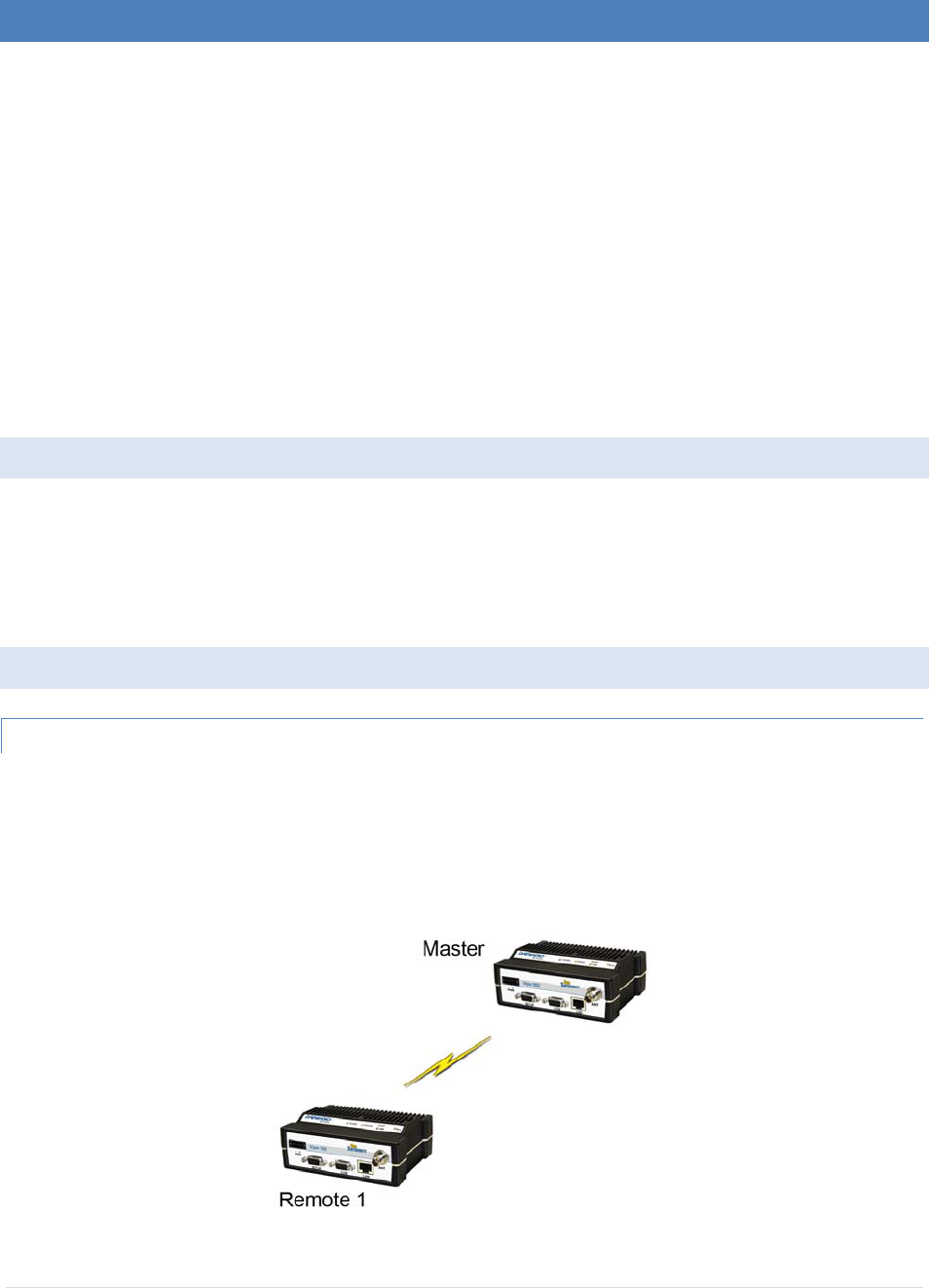
2.2.1 POINT‐TO‐POINT
Apoint‐to‐pointnetworkisthemostsimpleofallnetworks,andmaybeusedforconnectingapairofPC's,ahost
computerandaterminal,aSCADApollingmasterandoneremote,mobileapplications(likein‐vehicleGPS
receiversandbasestations)orawidevarietyofothernetworkingapplications.
Figure2.1–Point‐to‐PointNetwork
GuardianManual001‐5006‐000Rev018|Page
2.2.2 POINT‐TO‐MULTIPOINT
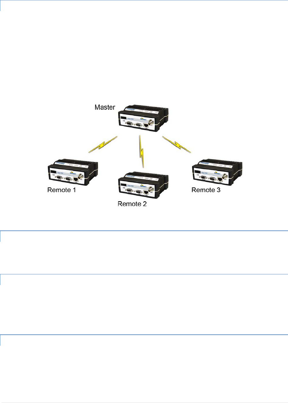
APoint‐to‐MultipointnetworkisacommonnetworktypeusedinSCADAorotherpollingsystems.Thesingle
pollingmasterstationcommunicateswithanynumberofremotesandcontrolsthenetworkbyissuingpollsand
waitingforremoteresponses.IndividualPLC/RTUremotesmanageaddressingandrespondwhentheirindividual
addressesarequeried.PLC/RTUunitaddressesaremaintainedinascanningliststoredinthehostprogramor
masterterminaldeviceattheSCADAhostsite.Communicationsequipmentistransparentanddoesnotinteract
withspecificremotes;alldataiscoupledtothehostonasingledataline(suchanetworkiscommonlyusedwith
synchronousradiomodemsandasynchronousradiomodems).
Figure2.2–PointtoMultipointNetwork
2.2.3 MULTIPLEPOINT‐TO‐POINT
Amultiplepoint‐to‐pointissimilartothepoint‐to‐multipointsystemexcepttheSCADAhosthasmultipleserial
portsthataredirectedtodifferentgeographicareasintheSCADAsystem.
2.2.4 PEER‐TO‐PEER
APeer‐to‐Peernetworkisgenerallyusedfordevicetodevicecommunicationsamonganumberofstations.This
networkrequiresfulladdressingcapabilityonthepartofthedataequipment(DTE).Ifthedistancesinvolvedfor
anylinkorlinksaretoogreatforasingleradiohop,theycanbeextendedbymeansofrepeaterswithoutaffecting
thebasicnetworkdesign.
2.2.5 STOREANDFORWARD
StoreandForwardisacommontechniquewhereadatatransmissionissentfromonedevicetoareceivingdevice
butfirstpassesthrougharelayingdevice.ThedeviceistypicallyanRTUorPLCusedbythemessageserviceto
storethereceivedmessagethenittransmitsthemessagetotheintendedrecipient.

GuardianManual001‐5006‐000Rev019|Page
2.2.6 NETWORKUSINGAT‐BASE
TheNetworkUsingaT‐Baseconfigurationhasthefollowingcharacteristics:
Masterstationmaybefullduplex(duplexerrequired),halfduplex,orsimplex
OnlinediagnosticsareavailableusingtheOnlineDiagnosticsutilitywithoutdisruptingnetworkactivity
Remote/localdiagnosticsandstatistics/controlareavailableusingtheGuardianOfflineDiagnosticsutility
whenconnectedtotheTxmodule(notDiagPortofT‐Base)
TheT‐BaseprovidesoutputofOnlineDiagnosticinformationwhichcanbeprocessedbytheGuardianOnline
Diagnosticsutilityorbyauser‐suppliednetworkmanagementprogram.Contactyoursalesrepresentativefor
furtherinformation.
2.2.7 NETWORKUSINGAT‐BASEREPEATER
TheNetworkUsingaT‐BaseRepeaterhasthefollowingcharacteristics:
Masterstationandallremotesmustbehalfduplex
NetworksdescribedinSection1.10.2,1.10.3,or1.10.5maybeusedwithaT‐Baserepeater
TheRTS/CTSdelaysforeachGUARDIANinthesystemmustbeextendedasshowninTable2‐6,RTS/CTS
Delays
2.2.8 NETWORKUSINGAGUARDIANFORONLINEDIAGNOSTICS
TheNetworkUsingaGuardianforOnlineDiagnosticsconfigurationhasthefollowingcharacteristics:
Masterstationmaybehalfduplexorsimplex
Accumulatedonlinediagnosticsforamaximumof15stationsareavailableatamonitoringsite(monitoring
sitemustbeinrangeofallremotes)
OnlineDiagnosticsareavailableinrealtimeatthemonitoringsite
RemoteOfflineDiagnostics,statistics,andcontrolareavailablefromthemonitoringsitebytemporarily
disablingnetworkactivity(bestifusingaMasterStationAntennaSystem)
OnlineDiagnosticsareaccumulatedinthemonitoringGuardianforthelast15stationsheard.Thisinformation
maybeviewedusingtheOnlineDiagnosticsutility.Forlargernetworks,theGuardiancanoutputrawdiagnostic
dataonlywhichmaybeinterpretedfornetworkmanagementbytheCalampFieldProgrammingSoftwareOnline
Diagnosticsutilityorbyauser‐suppliedsoftwareprogram.Contactyoursalesrepresentativesformore
information.
GuardianManual001‐5006‐000Rev020|Page
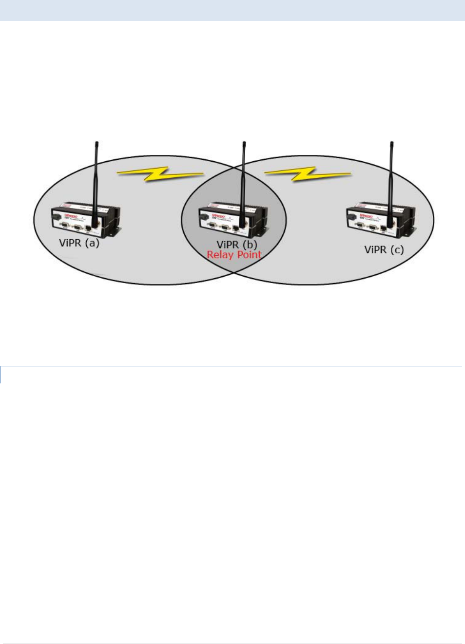
2.3 EXTENDINGTHECOVERAGEAREAWITHARELAYPOINT
TheGuardianhasaRelayPointfeaturethatallowsaunittorelaydatafromoneRFcoverageareatoanotherRF
coveragearea.Whenunitsarespreadovertwoormorecoverageareas,theusermustidentifythedevicesforming
thebackbonebetweencoverageareassoanyunitcantalktoanyotherregardlessoftheirlocations.Therecanbe
multipleRelayPointsinthesystemextendingthecoverageoverseveralhops.
Figure2.3‐TwoCoverageAreas
Theunitformingthebackbonebetweenthecoverageareasmustbeconfiguredtorepeatallnecessary
informationfromonecoverageareatothenext.ThisunitmusthavetheRelayPointparameterenabled(See
Section6.1).
2.3.1 UNDERSTANDINGRFPATHREQUIREMENTS
Radiowavesarepropagatedwhenelectricalenergyproducedbyaradiotransmitterisconvertedintomagnetic
energybyanantenna.Magneticwavestravelthroughspace.Thereceivingantennainterceptsaverysmall
amountofthismagneticenergyandconvertsitbackintoelectricalenergythatisamplifiedbytheradioreceiver.
TheenergyreceivedbythereceiveriscalledtheReceivedSignalStrengthIndication(RSSI)andismeasuredin
dBm.
AradiomodemrequiresaminimumamountofreceivedRFsignaltooperatereliablyandprovideadequatedata
throughput.Thisistheradio’sreceiversensitivity.Inmostcases,spectrumregulatorswilldefineorlimitthe
amountofsignalthatcanbetransmittedanditwillbenotedontheFCClicense.Thisistheeffectiveisotropic
radiatedpower(EIRP). Transmittedpowerdecayswithdistanceandotherfactorsasitmovesawayfromthe
transmittingantenna.

GuardianManual001‐5006‐000Rev021|Page
2.4 SITESELECTIONANDSITESURVEY
2.4.1 SITESELECTION
Forasuccessfulinstallation,carefulthoughtmustbegiventoselectingthesiteforeachradio.Suitablesitesshould
providethefollowing:
Protectionfromdirectweatherexposure
Asourceofadequateandstableprimarypower
Suitableentrancesforantenna,interface,orothercabling
Antennalocationwithanunobstructedtransmissionpathtoallremoteradiosinthesystem
Theserequirementscanbequicklydeterminedinmostcases.
2.4.2 SITESURVEY
ASiteSurveyisanRFpropagationstudyoftheRFpathbetweentwopointsorbetweenonepointandmultiple
points.UHFradiosignalstravelprimarilybylineofsightandobstructionsbetweenthesendingandreceiving
stationswillaffectsystemperformance.Signalpropagationisalsoaffectedbyattenuationfromobstructionssuch
asterrain,foliage,orbuildingsinthetransmissionpath.ASiteSurveyisrecommendedformostprojectsto
determinetheoptimalRFpathsforeachlink.ThisisespeciallytruewhenmorethanoneRFcoverageareais
required.ASiteSurveywilldeterminethebestunitlocationfortheRelayPoints.
2.5 SELECTINGANTENNAANDFEEDLINE
TheGuardiancanbeusedwithavarietyofantennatypes.Theexactstyleuseddependsonthephysicalsizeand
layoutofasystem.TheGuardiandevicehasbeentestedandapprovedwithantennashavingamaximumgainof
10dBi.
2.5.1 ANTENNAGAIN
Antennagainisusuallymeasuredincomparisontoadipole.Adipoleactsmuchlikethefilamentofaflashlight
bulb:itradiatesenergyinalmostalldirections.Onebulblikethiswouldprovideverydimroomlighting.Adda
reflectorcapableofconcentratingalltheenergyintoanarrowangleofradiationandyouhaveaflashlight.Within
thatbrightspotonthewall,thelightmightbeathousandtimesgreaterthanitwouldbewithoutthereflector.
Theresultingbulb‐reflectorcombinationhasagainof1000,or30dB,comparedtothebulbalone.Gaincanbe
achievedbyconcentratingtheenergybothverticallyandhorizontally,asinthecaseoftheflashlightandYagi
antenna.Gaincanbealsobeachievedbyreducingtheverticalangleofradiation,leavingthehorizontalalone.In
thiscase,theantennawillradiateequallyinallhorizontaldirections,butwilltakeenergythatotherwisewould
havegoneskywardsanduseittoincreasethehorizontalradiation.
GuardianManual001‐5006‐000Rev022|Page
Therequiredantennaimpedanceis50ohms.Toreducepotentialradiointerference,theantennatypeanditsgain
shouldbechosentoensuretheeffectiveisotropicradiatedpower(EIRP)isnotmorethanrequiredforsuccessful
communication.
SeeTable1.7foralistoftestedantennarecommendations.TheseantennasareFCCapprovedforusewiththe
Guardian.Similarantennatypesfromothermanufacturersareequallyacceptable.Itisimportanttofollowthe
manufacturer’srecommendedinstallationproceduresandinstructionswhenmountinganyantenna.
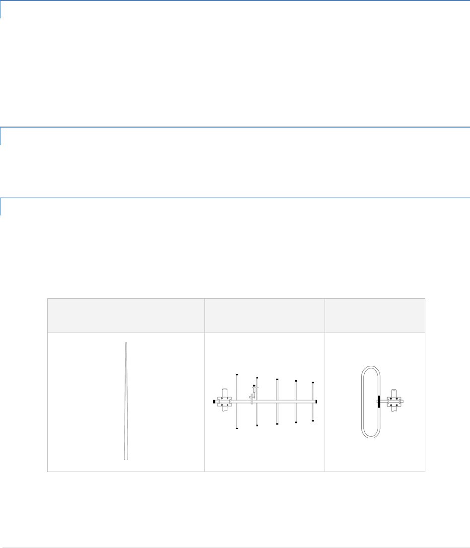
2.5.2 OMNIDIRECTIONALANTENNA
Ingeneral,anomnidirectionalantennashouldbeusedatamasterstationandRelayPoints.Thisallowsequal
coveragetoalloftheremotelocations.OmnidirectionalantennasaredesignedtoradiatetheRFsignalina360‐
degreepatternaroundtheantenna.Shortrangeantennassuchasfoldeddipolesandgroundindependentwhips
areusedtoradiatethesignalinaballshapedpatternwhilehighgainomniantennas,suchasacollinearantenna,
compresstheRFradiationsphereintothehorizontalplanetoprovidearelativelyflatdiscshapedpatternthat
travelsfurtherbecausemoreoftheenergyisradiatedinthehorizontalplane.
2.5.3 YAGIANTENNA
Atremotelocations(notusedasaRelayPoint),adirectionalYagiisgenerallyrecommendedtominimize
interferencetoandfromotherusers.
2.5.4 VERTICALDIPOLES
Verticaldipolesareveryoftenmountedinpairs,orsometimesgroupsof3or4,toachieveevencoverageandto
increasegain.Theverticalcollinearantennausuallyconsistsofseveralelementsstackedoneabovetheotherto
achievesimilarresults.
Figure2.4‐AntennaTypes
Omni(VerticalCollinear)YagiVerticalDipole
GuardianManual001‐5006‐000Rev023|Page
2.5.5 FEEDLINE
Thechoiceoffeedlineshouldbecarefullyconsidered.Poorqualitycoaxialcablesshouldbeavoided,astheywill
degradesystemperformanceforbothtransmissionandreception.Thecableshouldbekeptasshortaspossibleto
minimizesignalloss.SeeTable2.1foralistoffeedlinerecommendations.
Table2.1‐TransmissionLoss(per100Feet)
FrequencyRange
CableTypeVHF UHF 900MHz
LMR‐4001.5dB 2.7dB 3.9dB
1/2”Heliax0.68dB 1.51dB 2.09dB
7/8”Heliax0.37dB 0.83dB 1.18dB
15/8”Heliax0.22dB 0.51dB 0.69dB
Outsidecableconnectionsshouldhaveaweatherkitappliedtoeachconnectiontopreventmoisture.Feedline
connectionsshouldberoutinelyinspectedtominimizesignallossthroughtheconnection.A3dBlossinsignal
strengthduetocablelossand/orbadconnectionsrepresentsa50%reductioninsignalstrength.
2.5.6 RFEXPOSURECOMPLIANCEREQUIREMENTS
TheGuardianradioisintendedforuseintheIndustrialMonitoringandControlandSCADAmarkets.TheGuardian
unitmustbeprofessionallyinstalledandmustensureaminimumseparationdistancelistedinthetablebelow
betweentheradiatingstructureandanyperson.Anantennamountedonapoleortoweristhetypicalinstallation
andinrareinstances,a1/2‐wavewhipantennaisused.
Table2.2–RFExposureComplianceMinimumSafetyDistances
Antenna Gain
5 dBi 10 dBi 15 dBi
Min Safety Distance
(VHF @ max power) 123cm 218.8cm 389cm
Min Safety Distance
(UHF @ max power) 105.7cm 188cm 334.4cm
Min Safety Distance
(900 MHz @ max power) 63.8cm 115 cm 201.7 cm
Note:ItistheresponsibilityoftheusertoguaranteecompliancewiththeFCCMPEregulationswhenoperating
thisdeviceinawayotherthandescribedabove.
TheGuardianradiousesalowpowerradiofrequencytransmitter.Theconcentratedenergyfromanantennamay
poseahealthhazard.Peopleshouldnotbeinfrontoftheantennawhenthetransmitteris
operating.
RF E

GuardianManual001‐5006‐000Rev024|Page
TheinstallerofthisequipmentmustensuretheantennaislocatedorpointedsuchthatitdoesnotemitanRFfield
inexcessofHealthCanadalimitsforthegeneralpopulation.Recommendedsafetyguidelinesforthehuman
exposuretoradiofrequencyelectromagneticenergyarecontainedintheCanadianSafetyCode6(availablefrom
HealthCanada)andtheFederalCommunicationsCommission(FCC)Bulletin65.
Anychangesormodificationsnotexpresslyapprovedbythepartyresponsibleforcompliance(inthecountry
whereused)couldvoidtheuser'sauthoritytooperatetheequipment.
2.6 TERRAINANDSIGNALSTRENGTH
Alineofsightpathbetweenstationsishighlydesirableandprovidesthemostreliablecommunicationslinkinall
cases.Alineofsightpathcanoftenbeachievedbymountingeachstationantennaonatowerorotherelevated
structurethatraisesithighenoughtoclearsurroundingterrainandotherobstructions.
Therequirementforacleartransmissionpathdependsonthedistancetobecoveredbythesystem.Ifthesystem
istocoveralimiteddistance,say3‐5miles,thensomeobstructionsinthetransmissionpathmaybetolerable.For
longer‐rangesystems,anyobstructioncouldcompromisetheperformanceofthesystem,orblocktransmission
entirely.
Thesignalstrength(RSSI)atthereceivermustexceedthereceiversensitivitybyanamountknownasthefade
margintoprovidereliableoperationundervariousconditions.Fademargin(expressedindB)isthemaximum
tolerablereductioninreceivedsignalstrength,whichstillprovidesanacceptablesignalquality.Thiscompensates
forreducedsignalstrengthduetomulti‐path,slightantennamovementorchangingatmosphericlosses.CalAmp
recommendsa30dBfademarginformostprojects.
Table2.3showstheRSSIversusReliability.Table2.3RSSIReliability
RSSIReliability
‐100dBmApproximately 50% reliability. Fading may cause frequent data loss.
‐90dBmApproximately90%reliability.Fadingwillcauseoccasionaldataloss.
‐80dBmApproximately99%reliability.Reasonabletolerancetomostfading.
‐70dBmApproximately99.9%reliabilitywithhightolerancetofading.
2.7 RADIOINTERFERENCE
Interferenceispossibleinanyradiosystem.However,sincetheGuardianisdesignedforuseinalicensedsystem,
interferenceislesslikelybecausegeographiclocationandexistingoperatingfrequenciesarenormallytakeninto
accountwhenallocatingfrequencies.
Theriskofinterferencecanbefurtherreducedthroughprudentsystemdesignandconfiguration.Allowadequate
separationbetweenfrequenciesandradiosystems.Keepthefollowingpointsinmindwhensettingupyourradio
system.
a. Systemsinstalledinlightlypopulatedareasareleastlikelytoencounterinterference,whilethoseinurban
andsuburbanareasaremorelikelytobeaffectedbyotherdevices.

GuardianManual001‐5006‐000Rev025|Page
b. Directionalantennasshouldbeusedattheremoteendofthelink.Theyconfinethetransmissionand
receptionpatterntoacomparativelynarrowbeam,whichminimizesinterferencetoandfromstations
locatedoutsidethepattern.
c. Ifinterferenceissuspectedfromanothersystem,itmaybehelpfultouseantennapolarizationopposite
totheinterferingsystem’santennas.Anadditional20dB(ormore)ofattenuationtointerferencecanbe
achievedbyusingoppositeantennapolarization.
d. CheckwithyourCalAmpsalesrepresentativeorCalAmpTechnicalServicesforadditionaloptions.The
TechnicalServicesgrouphasqualifiedpersonneltohelpresolveyourRFissues.
GuardianManual001‐5006‐000Rev026|Page
3 SETUPANDCONFIGURATION
ItiseasytosetupaGuardiannetworktoverifybasicunitoperationandexperimentwithnetworkdesignsand
configurations.
3.1 INSTALLTHEANTENNA
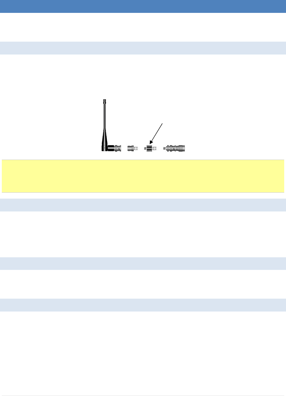
AnRX/TXantennaisrequiredforbasicoperation.Fordemounitsonly,connecttheantennaasshowninFigure3.1
toprovidestableradiocommunicationsbetweendemodevices.
Figure3.1‐DemoAntennaAssembly
Note:
Itisimportanttouseattenuationbetweenalldemounitsinthetestnetworktoreducetheamountofsignal
strengthinthetestenvironment.
3.2 MEASUREANDCONNECTPRIMARYPOWER
PrimarypowerfortheGuardianmustbewithin10‐30VDCandbecapableofprovidingaminimumof10watt
supplyforTx@1W,40wattsupplyforTx@5W,or60wattsupplyforTx@10W.(InGuardianDemoKits,a
powerconnectorwithscrew‐terminalsisprovidedwitheachunit.)Observeproperpolaritywhenconnectingthe
cablestothePowerSupply.(Whitewiremustbeconnectedtoredwire.)
3.3 CONNECTGUARDIANTOPROGRAMMINGPC
ConnectiontoaGuardianisestablishedthroughanRS‐232cableconnectedtothesetupportoftheGuardianand
theCOMportofthePC
3.4 GUARDIANFIELDPROGRAMMINGSOFTWARE
OperatingcharacteristicsoftheGuardianareconfiguredbytheFieldProgrammingSoftware.OfflineDiagnostics
andOnlineDiagnosticsgiveaccesstoOfflineDiagnosticsandcommands(localandremote)andonlinediagnostics
monitoring(withorwithoutaT‐Base/R).ProgrammingsoftwareisWindows®basedandrequiresaWindows95or
betteroperatingsystem.Contextsensitivehelpandprintablehelpfilesareprovidedwiththisprogram.
TheGUARDIANrequirestheuseoftheFieldProgrammingSoftwareforconfiguration,adjustmentand
diagnostics.
20 dB, 5watt max, attenuator

GuardianManual001‐5006‐000Rev027|Page
4 UNITSTATUS
TheUnitStatuswindowsdisplaydeviceGeneralandDiagnosticinformation.
4.1 UNITIDENTIFICATIONANDSTATUS
EachGuardianhasaddressingcapabilitywhichisusedfordiagnosticsandremotecommandsonly.
4.1.1.1 IDNUMBER
Thisvalue(maximum1023)isassignedatthefactorybutmaybemodifiedusingtheFieldProgrammingSoftware.
TheIDNumberisusedtouniquelyidentifytheGuardianforremotecommandsandOfflineDiagnostics.TheID
Numbermayhavevalueswithintherangeof1to4294967295butmultiplesof1024shouldnotbeused
4.1.1.2 SHORTID
Thisvalue(maximum1023)istheloworder10bitsoftheIDNumber.Itisusedtoidentifyonlinediagnosticsonly.
ItmaynotbemodifieddirectlyusingtheFieldProgrammingSoftware;itisalwaysderivedfromtheIDNumber.All
unitswithinanetworkshouldhaveuniqueShortIDnumberstoavoidambiguityinOnlineDiagnosticsreports.
TheGuardianFieldProgrammingSoftwaremaybeusedtocheckthevalueoftheShortID.Whensettingupa
network,werecommendcheckingeachunittomakesurethereisnoduplicationofShortIDnumbers.
DuplicationsmayberesolvedbychangingtheShortIDNumber.
IfIDNumbersaresetwithintherangeof1to1023,theIDNumberandtheShortIDwillalwayshavethesame
value(seeTable1‐4).
4.2 DIAGNOSTICS
Guardianunitscontinuallymonitorandreportontheirenvironmentalandoperatingconditions.
4.2.1 ONLINEDIAGNOSTICS
Informationisautomaticallysentbyeachunitatthebeginningofeverytransmission.
MaybedisabledforbackcompatibilitywithDataradioT‐Modem96orMotorolaRNet9600.OnlineDiagnostics
(statistics)requiretheuseofanetworkconfigurationsuchasthatspecifiedinthe“NetworkUsingT‐Base”or
“NetworkUsingGUARDIANforOnlineDiagnostics”sections.Onlinediagnosticsdonotinterferewithnormal
networkoperation.Onlinediagnosticsprovidefourtypesofinformation:
DCInputVoltage
TransceiverTemperature
PAForwardPower
PAReversePower

GuardianManual001‐5006‐000Rev028|Page
4.2.2 OFFLINEDIAGNOSTICS
Offlinediagnosticsarestatisticsreturnedinresponsetoaspecificrequesttoaparticularstation.Theuseofthis
featurerequirestemporarysuspensionofusernetworkoperation.Offlinediagnosticsprovideinformationthatis
displayedviatheOfflineDiagnosticsutility.OfflineDiagnosticsgatheranddisplaysfivetypesofinformation:
SupplyVoltage
Analogsupplyvoltage
Internaltemperature
Receivedsignalstrength(indBm)
Forwardandreversepowerinwatts
Preamblegood&total
PreambleDCD
4.2.3 REMOTECOMMANDS
RemotecommandsthatmaybesentusingtheOfflineDiagnosticsutilityinclude:
Getparameters(configuration)fromremoteunit
Samplenetworkstatistics(monitoringonlinediagnostics)
Getstatistics(diagnostics)

GuardianManual001‐5006‐000Rev029|Page
5 GUARDIANFIELDPROGRAMMINGSOFTWARE
5.1 INTRODUCTION
TheGuardianFieldProgrammingSoftwareprovidesprogramminganddiagnosticsfortheGuardianwireless
modem.TheFieldProgrammingSoftwareallowstheusertoeditandprogramuserprogrammablesettings,
interactivelytunemodemandRFparameters,andmonitordiagnosticdatafromtheGuardian.SeeFigure5‐1for
theGuardianFieldProgrammingSoftwarestartupscreen.
Figure5.1‐GuardianFieldProgrammingSoftwarestartupscreen
ThismanualassumestheFieldProgrammingSoftwarehasbeeninstalledontheuser’sPCwithatleastone
operationalserialCOMPortavailable.
5.1.1 COMPORTSETTINGS
GuardianprogrammingisdonethroughthePC’sPrimaryCOMPort.PrimaryandsecondaryCOMportsare
configuredwiththeFieldProgrammingSoftware.Theprogrammingcable(includedintheProgrammingKit‐DRL
partnumber250‐4006‐001)isconnectedfromtheSetupPortontheGuardiantothePC’sCOMportconfiguredas
thePrimaryPort.
ThePortSettingsscreenoftheFieldProgrammingSoftwareisaccessedviatheUtilitiespull‐downmenu(see
Figure2‐7).ThePortSettingsscreensareusedtoconfigurethePC’sserialCOMPorts.COMPortparametersare
definedin2.5.2.1.COMPortassignmentsaredisplayedinthebottomstatusbaroftheGuardianField
ProgrammingSoftwarescreen.
5.1.2 COMPORTPARAMETERS
COMPort
SelectsCOMPortnumber(COM1‐4)forPrimaryandSecondaryCOMPorts(seeFigure2‐6).
BaudRate
SelectsthecommunicationspeedforPrimaryandSecondaryCOMPorts.
DataBits
Selectsthenumberofdatabits(4‐8)transmittedorreceivedforthePrimaryandSecondaryCOMPorts.
Parity
SelectstransmissionorreceptionofanyParityBitsforthePrimaryandSecondaryCOMPorts.
StopBits
SelectsnumberofStopBits(1or2)transmittedorreceivedforthePrimaryandSecondaryCOMPorts.

GuardianManual001‐5006‐000Rev030|Page
DTREnable
UsedtoassertDTR(DataTerminalReady)lineoftheRS232PortwhentheportisopenforthePrimaryand
SecondaryCOMPorts.
SwapCOMPorts
SelectingtheSwapComPortsbuttonmovestheSecondaryCOMPortsettingstothePrimaryCOMPort(and
movesthePrimaryCOMPorttotheSecondarysettings).SinceGuardianprogrammingisdonethroughthePrimary
COMPort,thisisusefulwhentwounitsareconnectedtothePrimaryandSecondaryCOMPorts.ASwapCOM
Portsallowsthesecondunittobeprogrammedwithoutswitchingprogrammingcables.
5.1.2.1 PRIMARYANDSECONDARYPORTSETTINGSCOMMUNICATIONSMODES
TheModedropdownmenuconfiguresthecommunicationsmodeforthePrimaryandSecondaryPCPort.See
Table2‐6forCommunicationModesconfigurations.
Table5.1‐CommunicationModes
Mode Description
Sync/ESCwithNoHSSendsdatausingSync/byte‐stuffingprotocolwithouthandshaking.
BufferedwithNoHSSendsbuffereddatawithouthandshaking(thismoderequiredforDOX
operation.)
Sync/EscwithRTS/CTSHSSendsdatausingtheSync/Escbyte‐stuffingprotocolwithRTS/CTShardware
handshaking.
BufferedwithRTS/CTSHSSendsbuffereddatawithRTS/CTShardwarehandshaking.
Sync/EscwithFlowControlHSSendsdatausingtheSync/Escbyte‐stuffingprotocolwithflowcontrol
handshaking.
BufferedwithFlowControlHSSendsbuffereddatawithflowcontrolhardwarehandshaking.
GuardianManual001‐5006‐000Rev031|Page
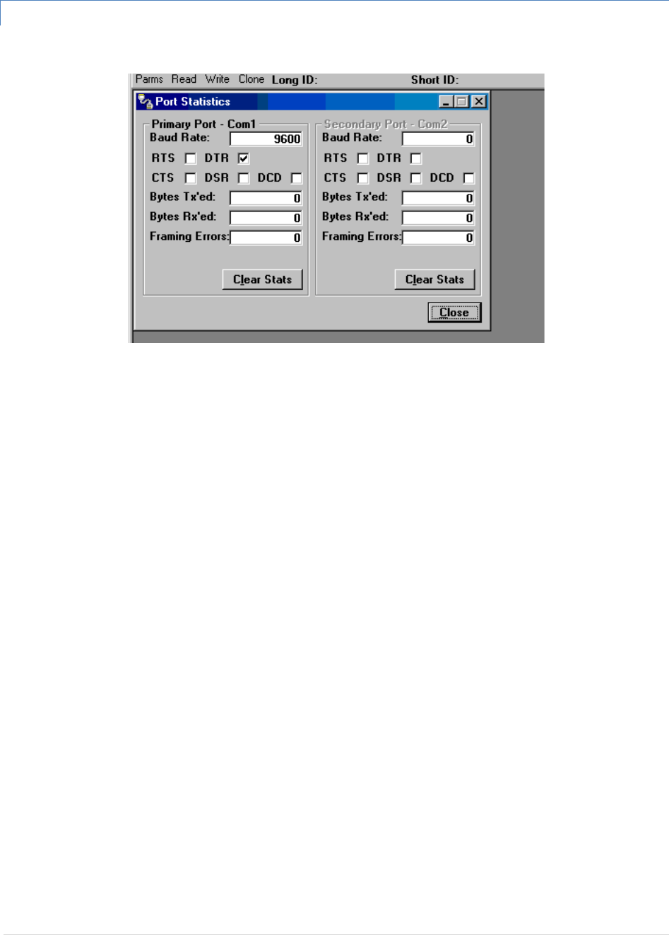
5.1.3 PORTSTATISTICS
Figure5.1PortStatisticsScreen
PortStatisticsshowcurrentparametersofthePC’sPrimaryandSecondaryCOMPorts.
BaudRate
BaudRateshowsthecurrentbaudratesettingforthePrimaryandSecondaryCOMports.
RTS
RTSshowsthecurrentstateoftheRTS(requesttosend)line.RTSisanoutputfromthePC.
DTR
DTRshowsthecurrentstateoftheDTR(dataterminalready)line.DTRisanoutputfromthePC.
CTS
CTSshowsthecurrentstateoftheCTS(cleartosend)line.CTSisaninputtothePC.
DSR
DSRshowsthecurrentstateoftheDSR(datasetready)line.DSRisaninputtothePC.
DCD
DCDshowsthecurrentstateoftheDCD(datacarrierdetect)line.DCDisaninputtothePC.
BytesTx’ed
BytesTransmittedshowsthenumberofbytes(characters)transmittedsincetheportwaslastopenedorcleared.
BytesRx’ed
BytesReceivedshowsthenumberofbytes(characters)receivedsincetheportwaslastopenedorcleared.
FramingErrors
FramingErrorsshowsthenumberofFramingErrorsreceivedsincetheportwaslastopenedorcleared.
GuardianManual001‐5006‐000Rev032|Page
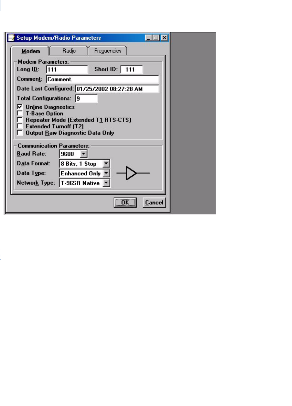
5.1.4 SETUPMODEM/RADIOPARAMETERS
Figure5.2SetupModem/RadioScreen
TheSetupModem/RadioParametersscreenisaccessedfromtheEditmenupull‐downorfromtheParmsicon
whenthetoolbarisvisible.
5.1.4.1 MODEMOPERATINGPARAMETERS
TheSetupModem/RadioParametersallowstheusertoviewandeditGUARDIAN’sprogrammableparameters.
Programmingparameterscanbestoredinadatafilewiththe.DATfileextension.Programmableparametersare
usedbytheRead/WriteParametersscreenforprogrammingintononvolatilememory.
Parametersettingsaremodifiedfromthreescreentabs:theModemtab,COM/Analogtab,andRadiotab.
Whendesiredparametersineachtabwindowhavebeenadjusted,selecttheOKbuttontostoretheparameter
informationintolocalPCmemoryandexittheparameterscreen.ClickingtheDefaultParmsbuttonsetscertain
parametersbacktofactorydefaultsettings.ClickingCancelexitstheparameterscreenwithoutmodifyingany
parameterscurrentlystoredinlocalPCmemory.

GuardianManual001‐5006‐000Rev033|Page
Modemoperatingparametersinclude:
LongID
TheelectronicIDNumberisauniquenumberassignedatthefactory.Thisnumbermaybechangedinthecaseofa
duplication.TheIDNumberisusedbytheprogrammerforremoteaddressinganddiagnostics.
Therangeofthisfieldis1to4294967295butmultiplesof1024shouldnotbeused.Amultipleof1024resultsina
ShortIDof0.IftheIDNumberiswithintherangeof1to1023,theShortIDwillbethesame.
NOTE:ThisIDisnotthesameastheprintedserialnumber.Usetheprintedserialnumbertoverifyiftheunitis
underwarranty.
ShortID
TheShortIDisderivedfromthelongerIDNumber.Itisusedtoidentifyunitsandminimizesthetimerequiredto
transmitOnlineDiagnostics.TheShortIDofeachunitinanetworkmustbeuniqueifOnlineor
OfflineDiagnosticswillbeused.SincetheShortIDisderivedfromtheIDNumber,noentryisallowedinthisfield.
TherangeoftheShortIDis1to1023.
Comment
TheCommentfieldcanbeusedasanotepad(i.e.,customername,location,technicalinfo...etccanbeenteredin
thisfield).Commentsaretextupto39charactersincludingspaces.
DateLastConfigured
TheDateLastConfiguredfieldshowsthedatetheunitwaslastprogrammed.Thedateistakenfromtheoperating
program.Noentryisallowedinthisfield.
TotalConfigurations
TheTotalConfigurationsfieldshowsthenumberoftimesaunithasbeenprogrammed.Noentryisallowedinthis
field.
OnlineDiagnostics
Ifenabled,diagnosticsinformationissentatthebeginningofeachtransmission.Diagnosticsinformationis
invisibletouserdataexceptfortheincreaseinRTS/CTSdelayof11ms(at9600b/s).Thedefaultvalueis“Enabled”
(checked).
Allunitsinanetworkmustusethesamesetting.Diagnosticsfromthelast15stationsheardarestoredineach
unit.ThesevaluesarereadusingtheOfflineorOnlineDiagnosticsscreen.
Transmittedinformationincludes:
• ShortID
• SupplyVoltage(inVolts)

GuardianManual001‐5006‐000Rev034|Page
• InternalTemperature(inCelsius)
• ForwardandReversePower(inWatts)
• ReceivedSignalStrength(indBm)
T‐BaseOption
AvailablewhenconnectedtoaGUARDIANWirelessModem,the“T‐BaseOption”makesthenecessarycircuit
changestoallowusingthemodemasaspecialdiagnosticunitintheT‐Base/R.Thedefaultvalueis“Disabled”
(unchecked).
RepeaterMode(ExtendedT1RTS‐CTSrefertoTable2‐8,page2‐13)
TheRepeaterModeoptionextendstransmitterturn‐ontimetoallowuseinarepeaternetwork.Thedefaultvalue
is“Disabled”(unchecked).
ExtendedTurn‐off(T2)
TheExtendedTurn‐offoptionextendstransmitterturn‐offtimetoenforceaquietperiodattheendofeach
transmission.Select“Enabled”ifdataequipmentdoesnotclearlyterminateeachdataframeandissusceptibleto
extraneousbits(dribblebits)attheendofdatatransmission.Thedefaultvalueis“Disabled”(unchecked).
Valuesare:4800b/s=16ms;9600b/s=8ms;19200b/s=4ms
Anend‐of‐transmissionquietperiodapproximately8characterslongcanbeinvokedontheGUARDIANbyholding
itstransmitteronbrieflyafterRTSisdropped.Thisquietperiod(whichoccursbetweenthelastvaliddata
characterandanypossibleextraneous“noise”bits)maybeofbenefittosomeDTEthatwouldotherwisebe
adverselyaffectedbytheextraneousbits.
OutputRawDiagnosticDataOnly
TheOutputRawDiagnosticDataOnlyoptioninstructsthemodemtoreceivediagnosticinformationreceivedfrom
othermodemsonly.Enablingthisoptiondisablesuserdatadelivery.Thisfunctionisprovidedtousewiththe
DiagnosticUnitincorporatedinaT‐BaseorT‐Base/R.Thedefaultvalueforthisoptionis“Disabled”(unchecked).
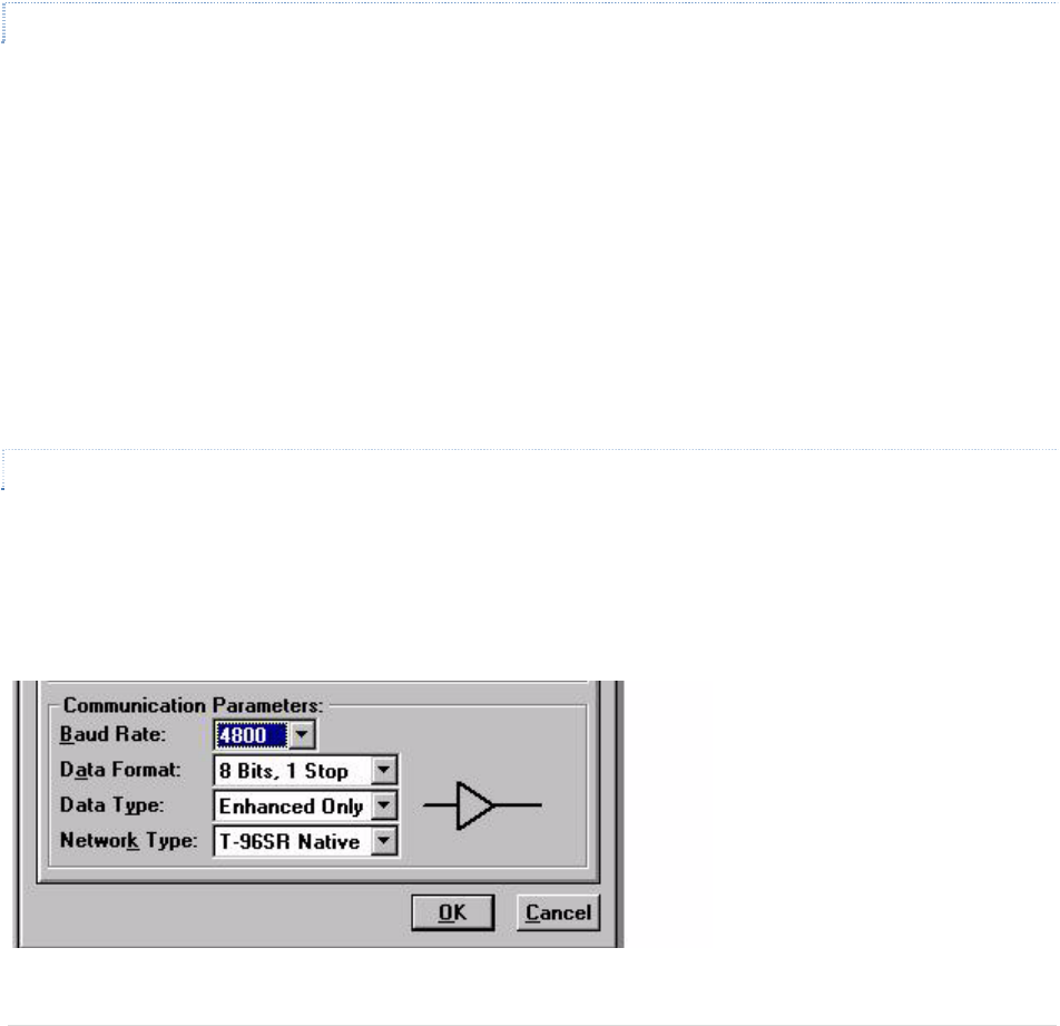
BaudRate
ThisfieldselectstheRS‐232InterfaceandNetwork(overtheair)baudrates.Table5.3listsprogramming
possibilitiesforthisfield.
Table5.2RTS/CTSDelays
DataFormat
TheDataFormatfieldselectsthewordlengthandnumberofstopbitsforthedatastream.Thefollowingoptions
areavailable*:
a.8DataBits,1StopBit
b.8DataBits,2StopBits

GuardianManual001‐5006‐000Rev035|Page
c.9DataBits,1StopBit
d.9DataBits,2StopBits
Table2‐8showssupporteduserformatsandmodemprogramming.
Note:AYesintheParitycolumnindicatesEven/OddorMark/SpaceParity.ANointheParitycolumnindicates
none.N/Ameansthecombinationisnotavailable.
Table5.3RS‐232InterfaceandNetworkBaudRates
ConfigurationBaudRates
Full‐ChannelGUARDIANin“GUARDIANNative”networktype4800,9600,19200
Half‐ChannelGUARDIANin“GUARDIANNative”networktype4800,9600
Full‐ChannelGUARDIANin“T‐96S/DL3276”networktype4800,9600
Half‐ChannelGUARDIANin“T‐96S/DL3276”networktype4800
Full‐ChannelT‐96S1200,2400,4800,9600
Table5.4SupportedUserFormatsandModemProgramming
DataBitsParityStopBitsModem*
7No1N/A
7Yes1a
7No2a
7Yes2b
8No1a
8Yes1borc
8No2borc
8Yes2d
9No1c
9Yes1d
9No2d
9Yes2N/A
RTS/CTSdelay(normal)RTS/CTSdelay(extended)
GuardianManual001‐5006‐000Rev036|Page
ProductMode
Speeddiag.offdiag.ondiag.offdiag.on
T‐96S4800b/s30ms54ms60ms85ms
T‐96S9600b/s30ms41ms60ms75ms
GUARDIAN9600b/s20ms32ms40ms55ms
GUARDIAN19200b/s20ms28ms40ms50ms
Note:If9DataBits,2StopBitsisselected,RemoteDiagnosticsorCommandsarenotsupportedandOnline
Diagnosticsmustbedisabledforpropernetworkdataoperation.Important:Allunitsinanetworkmustusethe
sameDataFormatsetting.
5.1.4.2 DATATYPE
DataTypebehaviorisdependentonthemodemconnectedtotheuserPC.
• ConnectedtoaGUARDIANModemoperatingin“GUARDIANNative”networktype:EnhancedOnlyData
Type
• ConnectedtoaGUARDIANModemoperatingin“T‐96S/DL3276”(orCrystal)networktype:Enhancedor
CompatibleDataType
Note:Choose“Compatible”ifthemodemistobeusedwithRNet9600S(crystal)orT‐Modem96(crystal)units
withserialnumbersbelow103500.Thebuffericontotherightofhisoptionwillturntoaninvertingbufferwhen
“Compatible”isselected.Choose“Enhanced”forotherapplicationstoachievebetterperformance.Important:All
unitsinanetworkmustusethesameDataFormatsetting.
5.1.4.3 NETWORKTYPE
InterdependentwithBaudRateandDataType,NetworkTypeallowsover‐the‐aircompatibilityandvaries
accordingtotheproductsusedinthenetwork.NetworkTypeisdependentonthemodemconnectedtotheuser
PC.
Figure5.3NetworkTypeConnectedtoaGUARDIANModem

GuardianManual001‐5006‐000Rev037|Page
Figure5.4NetworkTypeConnectedtoT‐96S/DL3276
ConnectedtoaGUARDIANModem,NetworkTypesinclude:
1. GUARDIANNative:availableBaudRateoptionsinclude4800/9600/19200forfull‐channelunitsor
4800/9600forahalf‐channelunits.DataTypeisEnhancedOnly
2. T‐96S/DL3276:availableBaudRateoptionsinclude4800/9600forfull‐channelunitsor4800forhalf‐
channelunits.DataTypeofferstwooptions:EnhancedandCompatible.Compatiblecausesthebuffericon
tochangetoaninvertingbuffer
3. Crystal:availableBaudRateoptionsinclude4800/9600forfull‐channelunitsor4800forhalf‐channel
units.DataTypeoffertwooptions:EnhancedandCompatible.Compatiblecausesthebuffericonto
changetoaninvertingbuffer.SelectingthisNetworkTypeextendsallRTS/CTSdelaysby5mSfor
compatibilitywithcrystalunits.
ConnectedtoaT‐96S/DL3276Modem,NetworkTypesinclude:
1. T‐96S/DL3276:availableBaudRateoptionsinclude1200/2400/4800/9600forfull‐channelunitsor
1200/2400/4800forhalf‐channelunits.DataTypesoffertwooptions:EnhancedandCompatible.
Compatiblecausesthebuffericontochangetoaninvertingbuffer
2. Crystal:availableBaudRateoptionsinclude1200/2400/4800/9600forfull‐channelunitsor4800forhalf‐
channelunits.DataTypeoffertwooptions:EnhancedandCompatible.Compatiblecausesthebuffericon
tochangetoaninvertingbuffer.SelectingthisNetworkTypeextendsallRTS/CTSdelaysby5msfor
compatibilitywithcrystalunits.
Caution: The 9600 Baud Rate (full-channel) in GUARDIAN Native Network Type has faster modem timing and
a higher deviation than the 9600 Baud Rate in the T-96S/DL3276 Network Type. The two are not
interchangeable.
GuardianManual001‐5006‐000Rev038|Page
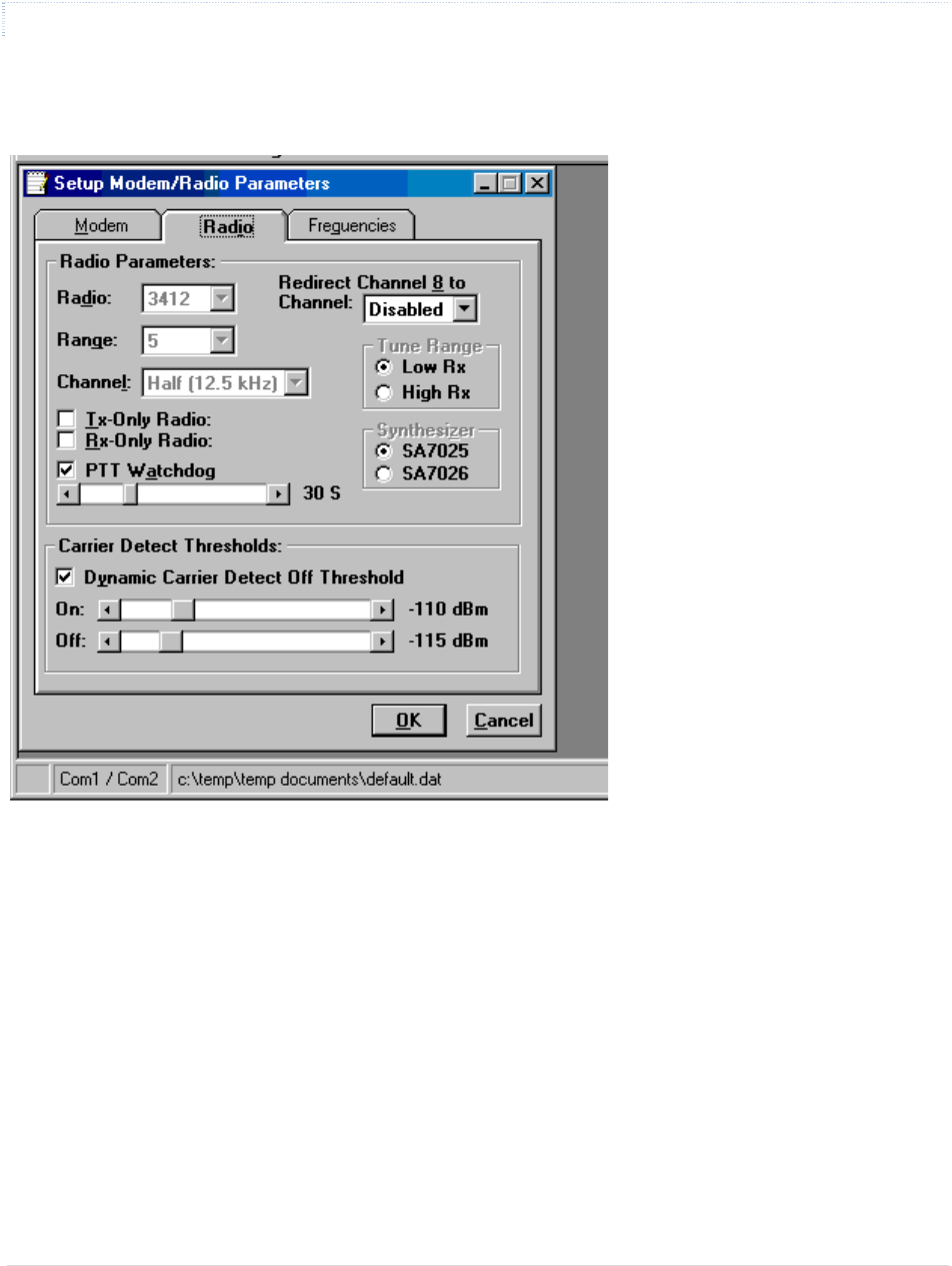
5.1.4.4 RADIOSETUPPARAMETERS
The Radio tab provides the interface for programming various radio operating parameters.
Figure5.5RadioSetupParametersScreen
Radio
Thisfielddesignatestheradiomodel.
Range
Thisfielddesignatesradiofrequencyrange.
Channel
Thisfieldspecifieswhethertheunitisfull‐orhalf‐channel(12.5or25kHz).
RedirectChannel8
TheRedirectChannel8fieldallowsChannel8tobedirectedtoanotherprogrammedchannel.Theunits’DIP
switchesmustbesettotheChannel8selectionforchannelredirectiontofunction.

GuardianManual001‐5006‐000Rev039|Page
TxOnlyRadio
TheTxOnlyRadiooptiondisablestheradio’sreceiverandanyabilityforthemodemtoreceivedata.Thisfunction
isprovidedforusewiththeTxunitincorporatedintoaT‐BaseorT‐Base/R.
RxOnlyRadio
TheRxOnlyRadiooptiondisablestheradio’stransmitterandanyabilityforthemodemtotransmitdata.This
functionisprovidedforusewiththeRxunitincorporatedintoaT‐BaseorT‐Base/R.
PTTWatchdog
ThePTTWatchdogallowstheusertosetthemaximumtransmittime.Thisisusedtoprotectagainsta‘stuck’
transmitter.Thetimeisselectedbyasliderbar.Therangeis0to120secondswithadefaultof30seconds.
Warning:Transmissionslongerthan30secondsmayexceedthedutycycleratingofthetransmitterandleadto
shortenedlifeortransmitterfailure.Afactory‐installedcoolingfanisavailableforextendeddutyoperations.For
continuous‐transmitapplications,thePTTWatchdogfeaturecanbedisabled(unchecked).
Synthesizer
Thisfieldliststhesynthesizermodelused.Thisfieldisnon‐selectableandforreferenceonly.
DynamicCarrierDetectOffThreshold
TheDynamicCarrierDetectOffThresholdallowsthemodemtoautomaticallyadjusttheCarrierDetectOff
ThresholdbasedontheRSSIwhilereceivingdata.Ifselected,theCarrierDetectOfflevelwillautomaticallyadjust
toapproximately15dBbelowtheactualsignalstrength.Thisprovidesrapiddetectionofloss‐of‐carrierand
minimizesoreliminates‘bitdribble’attheendoftransmissions.
Recommendation:KeepDynamicCarrierDetectOffThresholdenabled(checked)unlessinterferenceorvariable
signalstrength(i.e.,fadinginamovingvehicle)causesproblems.
CarrierDetectOnThreshold
CarrierDetectOnThresholdindicatesRSSIlevelwhenacarrierisfound.ThislevelshouldbemorethantheCarrier
DetectOffThreshold.
CarrierDetectOffThreshold
CarrierDetectOffThresholdindicatestheRSSIlevelwhenacarrierislost.ThislevelshouldbelessthantheCarrier
DetectOn.
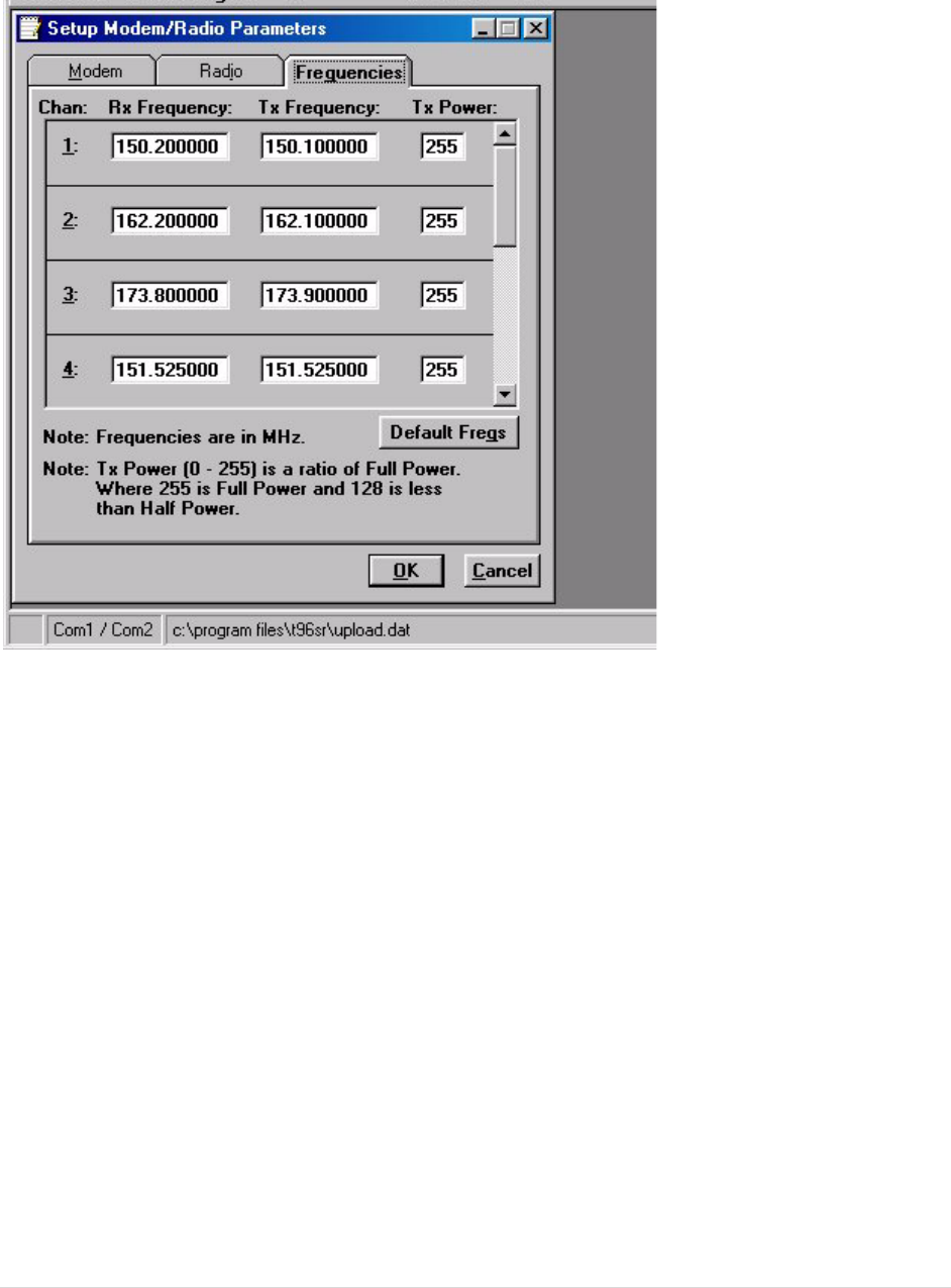
5.1.4.5 SETUPRADIO/MODEMFREQUENCIES
TheFrequenciestabprovidestheinterfacetoprogramfrequencypairsandtheircorrespondingpowersettings.
GuardianManual001‐5006‐000Rev040|Page
Figure5.6SetupRadio/ModemFrequenciesParameters
Chan
Chandisplaysthefrequencychannelpair.
RxFrequency
RxFrequencydisplaysthereceivefrequencyforthechannelpair.
TxFrequency
TxFrequencydisplaysthetransmitfrequencyforthechannelpair.
Power
PowerdisplaysthePowerOutputAdjustvalueforthechannelpair.Thedefaultvalueis255(5watts).Thisvalue
shouldbeleftatthedefaultvalueunless:
• alowerpowerisrequiredtomeetregulatoryrequirementsor
• theuser’sapplicationrequiresanincreaseinthetransmitdutycycle
DefaultFreqs
TheDefaultFreqsbuttonforcestheRxandTxFrequenciestotheirdefaultvalues,basedonradiotypeandrange.
GuardianManual001‐5006‐000Rev041|Page
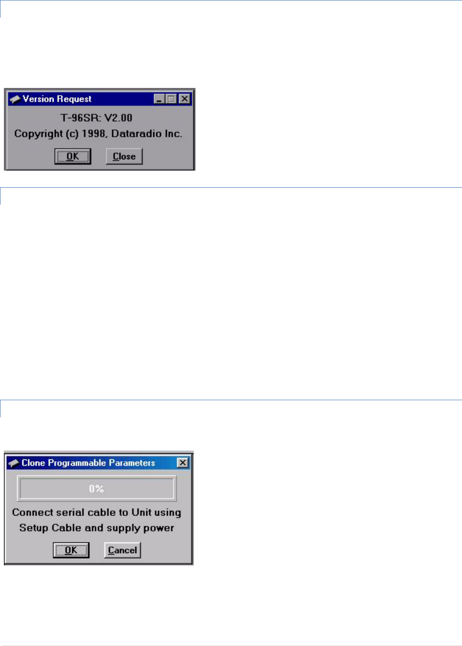
5.1.5 VERSIONREQUEST
SelectingVersionRequestcausestheGUARDIANFieldProgrammingSoftwaretodisplayinformationaboutthe
versionoftheGUARDIANhardwareandfirmware.
Figure5.7VersionRequestScreen
5.1.6 WRITING/READINGGUARDIANPARAMETERS
Afterallradioparametersaresetup,selecttheOKbuttontostoretheinformationintothePC’smemory.Toload
parametersintotheGUARDIAN,initiateaWriteProgrammableSettingsfromtheEditmenuorselecttheWrite
iconfromtheToolBar.AftertheprogrammableparametersareloadedintotheGUARDIAN,savetheparameter
informationusingtheSaveDataAsoptionintheFilepull‐downmenu.Thenameandlocationofthefile(*.dat
extension)willappearonthestatusbaratthebottomofthescreen.
TheReadProgrammableSettingscommandwillreadparametersfromthecurrentGUARDIANandstorethe
informationinlocalmemory.Theparameterscanbeviewedand/oreditedwiththeSetupModem/Radio
Parametersscreens.
Note:DataradiorecommendsaReadbedoneanytimeaninitialconnectionismadetotheGUARDIANSetupPort
beforeaccessingtheSetupModem/RadioParametersscreen.Thiswillhelpavoidwritingerroneousparametersto
theconnectedunit.
5.1.7 CLONEPROGRAMMABLEPARAMETERS
Figure5.8CloneProgrammableParametersScreen
TheCloneProgrammableSettingswritesthecurrentlyloadedsettings(excepttheIDNumber,Comment,and
NumberofWrites)totheEEPROMoftheGUARDIAN.ThisoptionisusedforprogrammingthesameDataFile(.dat)
intomultiplemodems.

GuardianManual001‐5006‐000Rev042|Page
5.1.8 DIAGNOSTICIDSANDALARMS
TheDiagnosticsIDsandAlarmsscreenallowstheusertosetuptheIDListforusewiththeOfflineLinkTestand
OfflineandOnlineDiagnosticsaswellastheAlarmsforusewithOnlineDiagnostics.
Figure5.9DiagnosticIDsandAlarmsScreen
IDEntryandList
IDEntryallowstheentryofaLongIDtobeaddedtotheIDList.Therangeofthisfieldis1to4294967295but
multiplesof1024shouldnotbeused.Amultipleof1024resultsinaShortIDof0.IftheLongIDiswithintherange
of1to1023,theShortIDwillbethesameortheresultingShortIDwillbesmallerthantheLongIDandwillbe
representedbya‘+’characterinfrontoftheID.ALongIDisaddedtotheIDListbyan‘Enter’orbypressingthe
AddIDbutton.
IDList:AllowstheusertoselectaLongIDfromthelisttodelete.ALongIDisdeletedfromthelistbypressingthe
DeleteIDbutton.
ShortID:ShowstheconvertedShortIDfromtheselectedLongIDoftheIDList.
AlarmsandFilters
AlarmsandFiltersareusedwithOnlineDiagnostics.WhenOnlineDiagnosticsarereceivedandadiagnosticfield
fallsoutsidetheAlarmlimits,a“<“characterwilldesignateavaluelessthanthelowAlarmanda“>”characterwill
designateavaluegreaterthantheHighAlarm.
WhenOnlineDiagnosticsarereceivedandadiagnosticfieldfallsoutsidetheFilterLimits,thediagnostic
informationisconsideredinvalidandisnotdisplayed.

GuardianManual001‐5006‐000Rev043|Page
Low/HighRSSI:Low/HighRSSIrepresentthelowandhighlimitsfortheRSSIdiagnostics(indBm).
Low/HighTemp:TheLow/HighTemprepresentsthelowandhighlimitsforthetemperaturediagnostics(in
degreesC).
Low/HighBatt:Low/HighBattrepresentsthelowandhighlimitsforthebatteryvoltagediagnostics(involts).
Low/HighFwdPwr:Low/HighFwdPwrrepresentsthelowandhighlimitsfortheforwardpowerdiagnostics(in
watts).
Low/HighRevPwr:Low/HighRevPwrrepresentsthelowandhighlimitsfortheReversePowerdiagnostics(in
watts).
Open
TheOpenbuttonallowstheusertorestoreDiagnosticIDsandAlarmsfromapreviouslysavedfile.
Save
TheSavebuttonallowstheusertosavethecurrentDiagnosticIDsandAlarmstothecurrentfile.
SaveAs
TheSaveAsbuttonallowstheusertosavethecurrentDiagnosticIDsandAlarmstoanamedifferentthanthe
currentfile.
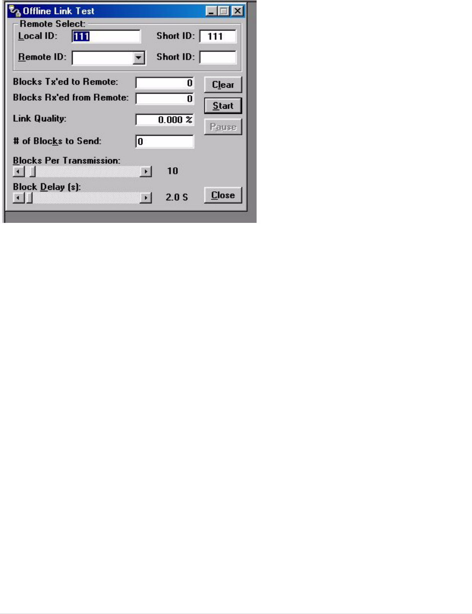
5.1.9 OFFLINELINKTEST
TheOfflineLinkTestisusedtotestthelinkbetweentwounits:thelocalunitinterfacedtothecomputeranda
remoteunit.Blocksofdataaretransmittedtotheremoteunitandtheremoteunitdecodesandreturnsthem.The
transmittedandreceivedblocksofdataarecomparedandtheratiooftheresultsarecalculated.
NOTE:AnOfflineLinkTestrequiressuspensionofusernetworkoperation.
RemoteSelect
LocalID
TheLocalIDistheLongIDoftheunitconnectedtothecomputer.TheShortIDisdisplayed.
RemoteID
TheRemoteIDcomboboxallowsselectionoftheunit(bychoosingitsRemoteID)fromwhichtheLinkTest
informationisgathered.RemoteIDsaresetupintheDiagnosticIDsandAlarmsScreen.TheShortIDisdisplayed.
AnOfflineLinkTestreturnsthefollowingstatistics:
GuardianManual001‐5006‐000Rev044|Page
Figure5.10OfflineLinkTestScreen
BlocksTx’edtoRemote
BlocksTx’edtoRemotedisplaysthenumberofdatablockstransmittedtotheremoteunit.
BlocksRx’edfromRemote
BlocksRx’edfromRemotedisplaysthenumberofdatablocksreceivedfromtheremoteunit.
LinkQuality
LinkQualitydisplaystheratioofdatablocksreceivedtodatablockstransmitted(in%).
#ofBlockstoSend
#ofBlockstoSendallowstheusertodeterminethenumberofblockstosendbeforestopping(with0being
disabled).
BlocksPerTransmission
Allowstheselectionofthenumberofblockspertransmission(1to200blocks).
BlockDelay(s)
BlockDelay(s)allowstheusertodeterminethedelaybetweenthetransmissionofdatablocksin0.05second
intervals(0.00to120.00seconds).
Clear
Clearallowstheusertoclearthedisplay(blockstransmitted,blocksreceivedandlinkquality).

GuardianManual001‐5006‐000Rev045|Page
Start
Startisusedtobeginthetest.
Pause
Pauseisusedtopausethetestandallowstheusertoresumethetestatalatertime.
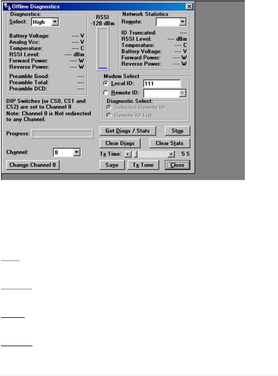
5.1.10 OFFLINEDIAGNOSTICS
OfflineDiagnosticsarereturnedfromalocalorremoteunitinresponsetoaGetDiagsrequest(seeFigure2‐18).
AnOfflineDiagnosticsrequestrequiressuspensionofusernetworkoperation.
Diagnostics
Select
SelectallowstheusertochooseCurrent,LoworHighDiagnostics.Currentshowsthevalueofthelastrequested
parameters.LoworHighdisplaysthelowestorhighestvalueoftheparameterssincethelastClearwasperformed
orthelasttimepowerwasremoved.
OfflineDiagnosticsparametersincludethefollowing:
• BatteryVoltage:supplyvoltage
• AnalogVcc:AnalogCircuitsRegulated5Vline
• Temperature:internalcasetemperature(inCelsius)listcontinuedonnextpage
• RSSILevel:ReceivedSignalStrengthIndication(indBm)
• ForwardPower:ForwardPower(inwatts)
• ReversePower:ReversePower(inwatts)
• PreambleGood:thenumberofcorrectlydecodedtransmissionsreceivedinthelast15.Usedwith
PreambleTotal,thisservesasanindicationofhowwelltheunitisreceivingdata
• PreambleTotal:thenumberoftotaltransmissionsdetected,maximumis15.UsedwithPreambleGood,
thisservesasanindicationofhowwelltheunitisreceivingdata
• PreambleDCD:thisnumbershowsacountofallreceivedCarrierDetects
GuardianManual001‐5006‐000Rev046|Page
Figure5.11OfflineDiagnosticsScreen
NetworkStatistics
OfflineNetworkStatisticsareonlyavailablewhenthe‘OnlineDiagnostics’optionisenabledforthenetwork.
OnlineDiagnosticsarelocatedontheSetupModem/RadioParametersscreen.Whenenabled,diagnostic
informationisinsertedatthebeginningofeachtransmissionfromeachunitinthenetwork.Whilethenetwork
mayremainonline,themonitoringunitisin‘Setup’mode(flashinggreenLED).
NetworkStatisticsinclude:
Remote
TheRemotedropdownallowstheusertoselect(fromthelistRemotes)whichnetworkstatisticstodisplay.
IDTruncated
IDTruncatedshowstheusertheLongandShortIDarenotthesame.
RSSILevel
TheRSSIlevelshowsthecurrentRSSIlevel(indBm)whiletheLocalunitisreceiving.
Temperature
Temperatureshowstheinternalcasetemperature(inCelsius).

GuardianManual001‐5006‐000Rev047|Page
BatteryVoltage
BatteryVoltageshowsthesupplyvoltage(inVolts).
ForwardPower
ForwardPowershowsforwardpower(inWatts).
ReversePower
ReversePowershowsreversepower(inWatts).
RSSIPanel
TheRSSIpanelshowsthecurrentRSSIlevel(indBm)whilethelocalunitisreceiving.
ModemSelect
LocalID
TheLocalIDbuttonallowstheusertosendcommandstothelocalunit(theunitinterfacedtothecomputer).The
ShortIDforthisunitisshown.
RemoteID
TheRemoteIDbuttonallowstheusertosenddiagnosticcommandstoanyspecificremoteunitandobtainits
diagnosticinformation.TheRemoteIDisselectedfromthelistofRemoteIDssetupintheDiagnosticIDsand
Alarmsscreen.
DiagnosticSelect/SelectedRemoteID
ThisbuttonallowstheusertogatherOfflineDiagnosticsfromtheselectedRemoteIDonly.
DiagnosticSelect/RemoteIDList
ThisbuttonallowstheusertogatherOfflineDiagnosticsfromalltheIDsinthelistofRemoteIDs(includingthe
localunit).
Progress
TheProgresspaneldisplaystheprogressofobtainingRemoteDiagnostics.
Channel
Channelallowstheusertoselecttheprogrammedchannelofoperation.Thereare8programmedchannels.
ChangeChannel8
ChangeChannel8allowstheusertoredirectChannel8toanotherprogrammedchannel.Theunit’sDIPswitches
mustbesettotheChannel8selectionforchannelre‐directiontofunction.

GuardianManual001‐5006‐000Rev048|Page
GetDiags/Stats
TheGetDiagsbuttonallowstheusertosendthecommandforOfflineDiagnostics.Thecommandissenttothe
unitconnectedtothecomputeriftheLocalIDbuttonisselected.ThecommandissenttotheselectedRemoteID
iftheRemoteIDandSelectedRemoteIDbuttonsareselected.ThecommandissenttothelistofRemoteIDsifthe
RemoteIDandRemoteIDListbuttonsareselected.
Stop
TheStopbuttonallowstheusertostopanycommandsforOfflineDiagnosticsfrombeingsent.
ClearDiags
ClearDiagsclearstheunit’sonlinenetworkstatistics.
TxTime
TxTimeallowstheusertoselectthelengthoftimetheunitwilltransmitatone(inseconds)whentheTxTone
buttonispressed(1to60seconds).
Save
TheSavebuttonallowstheusertosavethecurrentOfflineDiagnosticstoafile.
TxTone
TheTxTonebuttoninstructstheunittotransmitatoneformodulationontheprogrammedtransmitfrequencyfor
adurationofTxTime.
5.1.11 ONLINEDIAGNOSTICS
OnlineDiagnosticsaretransmittedbyeachunitinanetworkbeforetheuser’sdataistransmitted.Allunitsmust
beprogrammedwiththeOnlineDiagnosticsparameterfoundontheSetupModem/RadioParametersscreento
receiveDiagnosticsfromasystem.TheunitthatthecomputerisinterfacedwithwilloutputOnlineDiagnosticsas
theyarereceived.ThisunitmusthavetheOutputRawDiagnosticDataOnlyparameterprogrammed(foundonthe
SetupModem/RadioParametersScreen).UsingOnlineDiagnosticsdoesnotrequiresuspensionofnetwork
operation.
OnlineDiagnosticsaresubjecttoalarmandfilterconditionsdefinedintheDiagnosticIDs,AlarmsandFiltersscreen
(seeFigure2‐15).WhenOnlineDiagnosticsarereceivedandadiagnosticfieldfallsoutsidethealarmlimits,a“<“
characterwilldesignateavaluelessthanthelowalarmanda“>”characterwilldesignateavaluegreaterthanthe
highalarm.IfOnlineDiagnosticsarereceivedandadiagnosticfieldfallsoutsidethefilterlimits,thediagnostic
informationwillbeconsideredinvalidandwillnotbedisplayed.
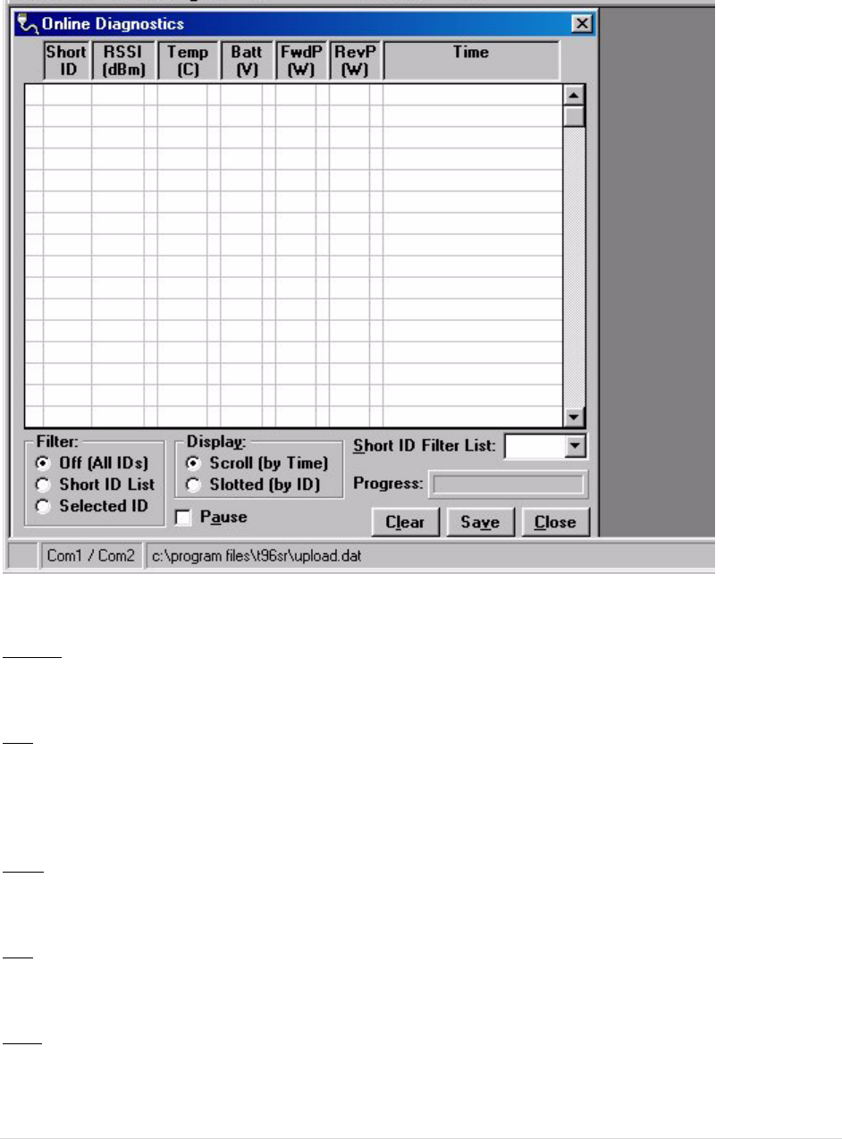
GuardianManual001‐5006‐000Rev049|Page
Figure5.12OnlineDiagnostics
ThefollowingOnlineDiagnosticsaregathered:
ShortID
TheShortIDdisplaystheShortIDoftheunittransmittingthediagnostics.
RSSI
RSSI(ReceivedSignalStrengthIndicator)displaystheRSSI(indBm)IDoftheunittransmittingthe
diagnostics.ThisistheRSSIsampledduringthelasttransmissionreceived.
Temp
Tempdisplaystheinternalcasetemperature(inCelsius)oftheunittransmittingthediagnostics.
Batt
Battdisplaysthesupplyvoltage(involts)oftheunittransmittingthediagnostics.
FwdP
FwdPdisplaystheforwardpower(inwatts)oftheunittransmittingthediagnostics.

GuardianManual001‐5006‐000Rev050|Page
RevP
RevPdisplaysthereverse(reflected)power(inwatts)oftheunittransmittingthediagnostics.
Time
Timeisthetimestampwhenthediagnosticswerereceived.
Filter
FilterallowstheusertofilterShortIDs.Thefollowingoptionsareavailable:
• Off(AllIDs):noIDsarefilteredout
• IDList:onlytheIDsintheFilterIDListareshown
• SelectedID:onlytheselectedIDintheFilterIDListisshown
Display
Displayallowstheusertoformatonscreendata.Thefollowingoptionsareavailable:
• Scroll(bytime):displaysthediagnosticsastheyarereceived
• Slotted(byID):sortsthediagnosticsbyShortID.Usingthisoption,eachShortIDwillhaveonerowof
diagnostics,showingthemostrecent
ShortIDFilterList
FilterIDListisalistingofRemoteIDssetupintheDiagnosticIDsandAlarmsScreen.Thislistisusedforselectinga
filter.
Progress
TheProgresspanelshowsthesortingprogressofthediagnosticsifafilterwaschanged.
Pause
ThePausecheckboxallowstheusertopausethereceptionofthediagnosticsforscrollingthroughthegrid.
Clear
TheClearbuttonallowstheusertoclearthedisplayandcurrentOnlineDiagnostics.
Save
TheSavebuttonallowstheusertosavethecurrentOnlineDiagnosticstoafile.Amaximumof4096linesofdata
canbesaved.
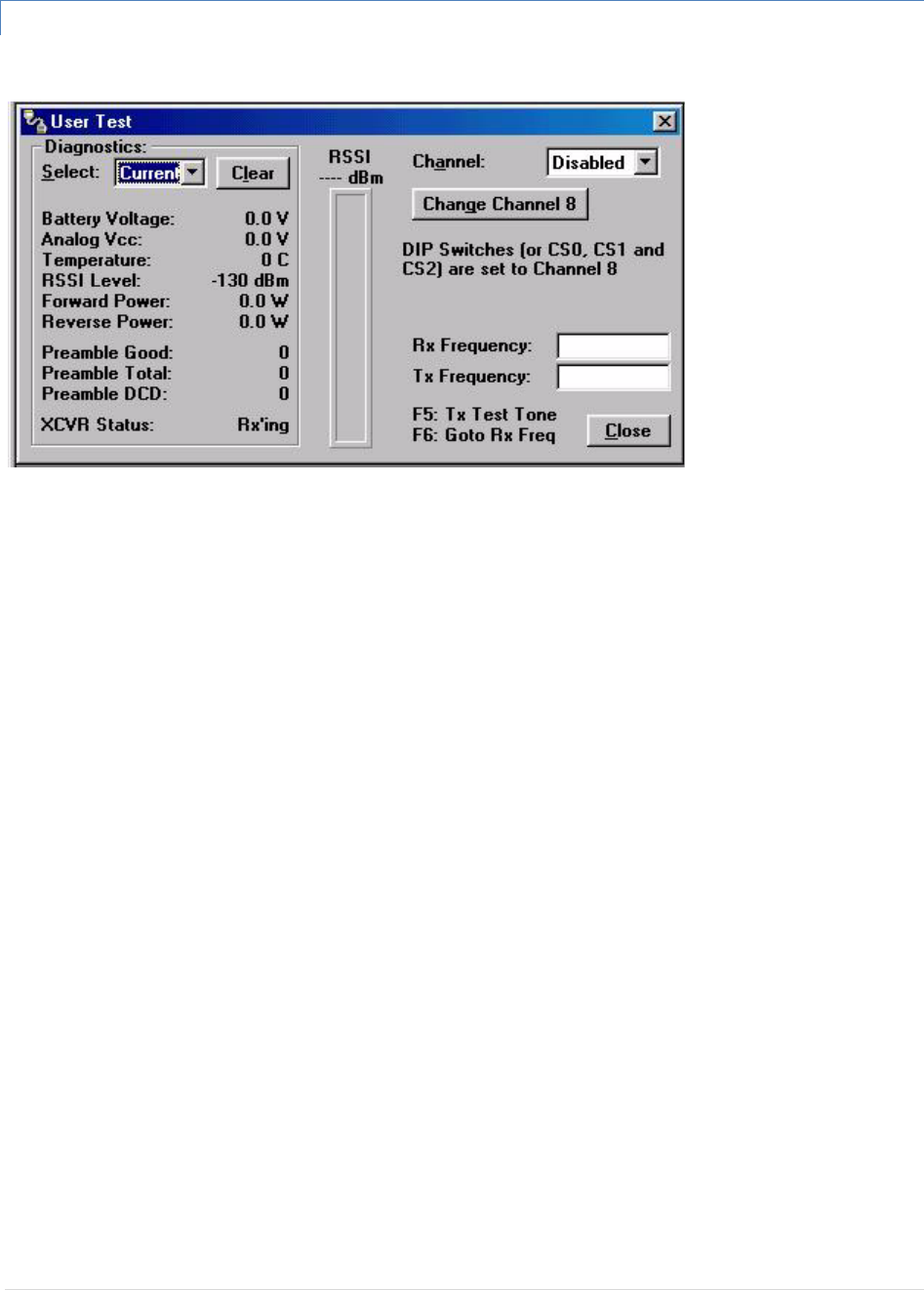
GuardianManual001‐5006‐000Rev051|Page
5.1.12 USERTEST
Figure5.13UserTestScreen
TheUserTestutilityisanOfflinefunctionandrequiressuspensionofnetworkoperation.AUserTest’sdiagnostic
parametersinclude:
RSSILevel
ReceivedSignalStrengthIndication(indBm)
BatteryVoltage
Supplyvoltage(involts)
Temperature
Internaltemperature(indegreesCelsius)
ForwardPower
Forwardpower(inwatts)
ReversePower
Reversepower(inwatts)
PreambleGood
Thenumberofcorrectlydecodedtransmissionsreceivedinthelast15.UsedwithPreambleTotal,thisservesasan
indicationofhowwelltheunitisreceivingdata.
PreambleTotal
Thenumberoftotaltransmissionsdetected,maximumis15.UsedwithPreambleGood,thisservesasan
indicationofhowwelltheunitisreceivingdata.
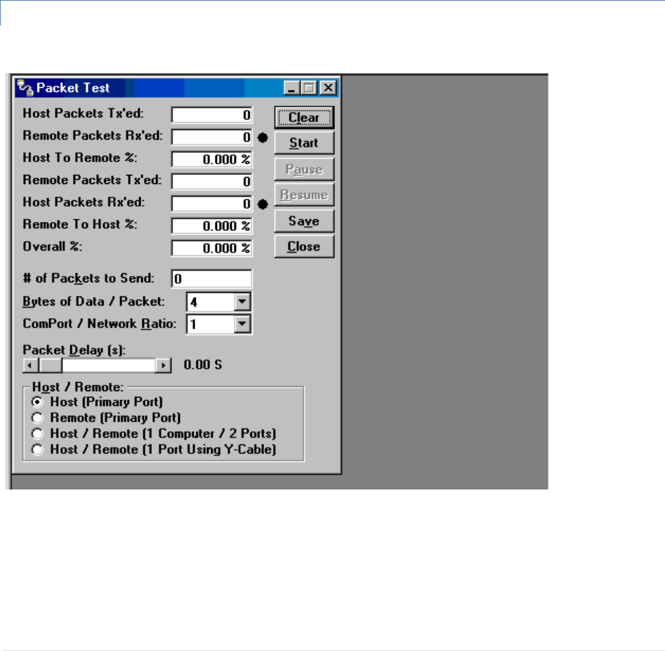
GuardianManual001‐5006‐000Rev052|Page
RSSI
ThispanelshowsthecurrentRSSIlevel(indBm)whilethelocalunitisreceiving.
Rx/TxFrequency
Rx/TxFrequencyshowsthecurrentreceiveandtransmitfrequencies.
F5
PressingtheF5keywillcausetheunittotransmitontheprogrammedtransmitfrequency.
F6
PressingtheF6keywillcausetheunittogotoreceiveontheprogrammedreceivefrequency
5.1.13 PACKETTEST
Figure2‐20PacketTestScreen
ThePacketTestscreenisusedtosimulateaHost/Remotepollingenvironment.TheMasterunitwillsendouta
packettotheRemoteandtheRemotewillreplytotheMasterwiththesamepacketinformation.Thisisauseful
utilityfortestingmodemcommunication.
HostPacketsTx’ed
HostPacketstransmittedshowsthenumberofdatapacketstheMasterhassenttotheRemote.

GuardianManual001‐5006‐000Rev053|Page
RemotePacketsRx’ed
HostPacketsreceivedshowsthenumberofdatapacketstheRemotedevicehasreceivedfromtheMaster.
HosttoRemote%
HosttoRemotepercentageshowsthepercentageofpacketstheHostdevicehassuccessfullysenttotheRemote.
RemotePacketsTx’ed
RemotePacketstransmittedshowsthenumberofdatapacketsthattheRemotedevicehasreturnedtotheHost.
HostPacketsRx’ed
HostPacketsreceivedshowsthenumberofdatapacketstheHostdevicehasreceivedfromtheRemote.
RemotetoHost%
RemotetoHostpercentageshowsthenumberofpacketstheRemotedevicesuccessfullysenttotheHost.
Overall%
OverallpercentageshowsthepercentageofHostreceivedpacketsversusHosttransmittedpackets.
#ofPacketstoSend
NumberofPacketstoSendprogramsthenumberofpacketstheHostshouldsendtotheRemotebeforestopping.
BytesofData/Packet
BytesofData/PacketistheprogrammablenumberofdatabytesineachpackettheHostsends.TheRemotewill
respondwiththesamenumberofpackets.
COMPort/NetworkRatio
COMPort/NetworkRatioistheratiooftheCOMportbaudratetonetwork(overtheair)baudrateofamodem.
ThisisusedifthenetworkbaudrateisslowerthantheCOMportbaudrate.IftheCOMportbaudrateis9600and
thenetworkbaudrateis4800,settheratioto2.Ifthetwoarethesame,setthisfieldto1.
PacketDelay(s)
PacketDelay(s)isthenumberofsecondsfortheHosttodelaybetweensendingeachpacket.Thisfieldranges
from0.00to10.00seconds(in0.25secondintervals).
Host/Remote
Host/RemoteisusedtoconfigureCOMportoptions.
• Host(PrimaryPort)‐ConfigurestheprimaryCOMportastheHostdevice(thedeviceinitiatingpacketsto
theRemotedevice.
• Remote(PrimaryPort)‐ConfigurestheprimaryCOMportastheRemotedevice(thedevicerespondingto
thepacketsfromtheHostdevice).

GuardianManual001‐5006‐000Rev054|Page
• Host/Remote(1computer/2ports)‐ConfigurestheprimaryCOMportastheHostdeviceandthe
secondaryCOMportastheRemotedevice.Thisoptionrequiresacomputerwith2COMports.
Host/Remote(1PortusingaY‐cable)‐ConfigurestheprimaryCOMportastheHostandRemotedevice.
AY‐cableisrequiredforthisoption(withtransmitconnectionssplittothetransmittingdeviceandreceive
connectionssplittothereceivingdevice).Acomputerwith1COMportisutilizedforthisoption
Table2‐10Y‐CableConnections
PinName DB‐9 DB‐29 Computer Rx Tx
DCD 1 8 X X ‐
RxD 2 3 X X ‐
TxD 3 2 X‐X
DTR 4 20‐‐‐
GND 5 7 X X X
DSR 6 6‐‐‐
RTS 7 4 X‐X
CTS 8 5 X‐X
RI9 2 2‐‐‐
X=Requiresconnection
‐=Noconnection
5.1.14 ARRAYTEST
TheArrayTestscreenisusedtosendprogrammablelengthtestpackets.PacketsTx’ed‐totalnumberofpackets
transmitted.
#ofPacketstoSend
#ofPacketstoSendallowstheusertosetthetotalnumberofpacketstosendbeforestopping(fieldrangeis0to
unlimited)
Table2‐10Y‐CableConnections
PinNameDB‐9DB‐29ComputerRxTx
DCD18XX‐
RxD23XX‐
TxD32X‐X
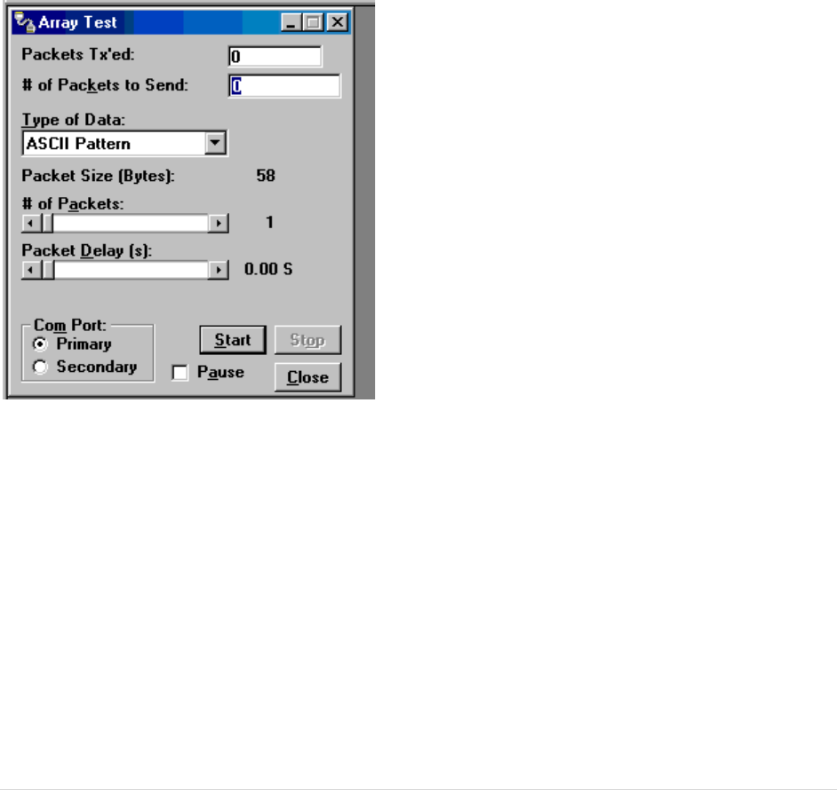
GuardianManual001‐5006‐000Rev055|Page
DTR420‐‐‐
GND57XXX
DSR66‐‐‐
RTS74X‐X
CTS85X‐X
RI922‐‐‐
X=Requiresconnection
‐=Noconnection
Figure2‐21ArrayTestScreen
TypeofData
TypeofDataallowstheusertoselectthedatapatternforeachpacket.Thesizeforeachdatapatternislistedin
thepatternformatexplanations(packetsarebuiltusingoneoffourpossiblepatterns).
• ASCIIPattern‐Packetsare58charactersinlengthandhaveasequencenumberatthebeginningofeach
stringstartingwith000,incrementingto999thenwrappingaroundto000again
Thepatternusedtobuildthepacketswillhavethefollowingformat(inASCII):
000ABCDEFGHIJKLMNOPQRSTUVWXYZabcdefghijklmnopqrstuvwxyz
001ABCDEFGHIJKLMNOPQRSTUVWXYZabcdefghijklmnopqrstuvwxyz
‐‐‐
998ABCDEFGHIJKLMNOPQRSTUVWXYZabcdefghijklmnopqrstuvwxyz

GuardianManual001‐5006‐000Rev056|Page
999ABCDEFGHIJKLMNOPQRSTUVWXYZabcdefghijklmnopqrstuvwxyz
000ABCDEFGHIJKLMNOPQRSTUVWXYZabcdefghijklmnopqrstuvwxyz
001ABCDEFGHIJKLMNOPQRSTUVWXYZabcdefghijklmnopqrstuvwxyz
‐‐‐
• ASCIINumberPattern‐Thepacketswillbe58charactersinlengthandhaveasequencenumberatthe
beginningofeachstring,startingat000andincrementingto999,thenwrappingaroundto000again.
Thepatternusedtobuildthepacketswillhavethefollowingformat(inASCII):
00000112233445566778899AABBCCDDEEFF
00100112233445566778899AABBCCDDEEFF
‐‐‐
99800112233445566778899AABBCCDDEEFF
99900112233445566778899AABBCCDDEEFF
00000112233445566778899AABBCCDDEEFF
00100112233445566778899AABBCCDDEEFF
‐‐‐
• BinaryPattern‐Thepacketswillbe16charactersinlengthandhaveasequencenumberevery16characters,
startingat0x00andincrementingto0xFF,thenwrappingaroundto0x00again.
Thepatternusedtobuildthepacketswillhavethefollowingformat(inHex):
00112233445566778899AABBCCDDEEFF
01112233445566778899AABBCCDDEEFF
02112233445566778899AABBCCDDEEFF
‐‐112233445566778899AABBCCDDEEFF
FE112233445566778899AABBCCDDEEFF
FF112233445566778899AABBCCDDEEFF
00112233445566778899AABBCCDDEEFF
01112233445566778899AABBCCDDEEFF
02112233445566778899AABBCCDDEEFF
‐‐112233445566778899AABBCCDDEEFF
• RandomBinaryPattern‐Thepacketswillbe16charactersinlengthandcontainrandombinarydata.
#ofPackets
#ofPacketsallowstheusertosetthenumberofpacketsineachtransmission.
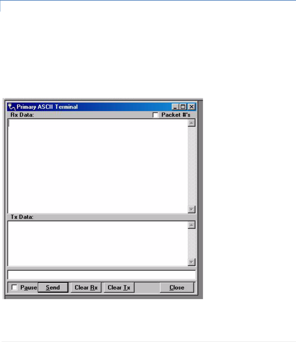
GuardianManual001‐5006‐000Rev057|Page
PacketDelay
PacketDelayallowstheusertosettheamountoftime(inseconds)todelaybetweeneachpackettransmission,
rangingfrom0.00to30.00seconds(in0.25secondintervals).
ComPort
ComPortallowstheusertoselecttheCOMport(primaryorsecondary)fordatatransmission.
5.1.15 ASCII/HEXTERMINAL
TerminalScreensallowtheusertoselectanASCIIorHexadecimalTerminalScreenforthePrimaryandSecondary
COMPorts(configuredinthePortSettingsscreen‐seeSection2.5.2.1)Dataissentaccordingtotheport
configurationsetupinthePortSettingsscreen.
ASCII/HEXTERMINALTerminalScreensallowtheusertoselectanASCIIorHexadecimalTerminalScreenforthe
PrimaryandSecondaryCOMPorts(configuredinthePortSettingsscreen‐seeSection2.5.2.1)Dataissent
accordingtotheportconfigurationsetupinthePortSettingsscreen.
Figure2‐22ASCIITerminalScreen

GuardianManual001‐5006‐000Rev058|Page
5.1.15.1 ASCIITERMINAL
ASCIITerminalconfigurationsinclude:
Primary
ThePrimaryASCIITerminalscreensendsandreceivesASCIIdataonthePrimaryCOMPort(setupinthePort
Settingsscreen).
Secondary
TheSecondaryASCIITerminalscreensendsandreceivesASCIIdataontheSecondaryCOMPort(setupinthePort
Settingsscreen).
5.1.15.2 HEXTERMINAL
HexTerminalconfigurationsinclude:
Primary
ThePrimaryHexTerminalscreenselectsaHexadecimalTerminalscreentosendandreceiveHexadecimaldataon
thePrimaryCOMPort(setupinthePortSettingsscreen).
Secondary
TheSecondaryHexTerminalscreenselectsaHexadecimalTerminalscreentosendandreceiveHexadecimaldata
ontheSecondaryCOMPort(setupinthePortSettingsscreen).
5.1.16 PROGRAMCODE
TheProgramCodepull‐downmenuallowstheusertoupdatetheGUARDIANfirmware(*.bin)withtheProgram
Firmwareoption.SelectModemCodeFileallowstheusertoselectthefiletoprogramthefirmwareinthe
GUARDIAN.
5.1.17 ENDTOENDTEST
TwoDataradioGUARDIANscanbetestedusingtheDataradioGUARDIANFieldProgrammingSoftware.TheField
ProgrammingSoftwarehasseveralusefulutilitiesembeddedintheprogramthatassistintestingthewireless
modems.ThetestingsetuprequiresacomputerrunningtheFieldProgrammingSoftwareattachedtoeachuser
COMportontheGUARDIANwirelessmodems.TheUtilitieswillallowtheusertosendASCIItextorHexcharacters
throughtheGUARDIANsbeingtested.
TheGUARDIANsmustbesetupsothattheyhavetheappropriatereceiveandtransmitsignallevelsforthetest.
Thesignalstrengthwillbemuchstrongeriftheunitsaretestedonthebenchcomparedtobeingtestedinafield
installation.Thesesignalsmustbeattenuatedortheoutputpowerleveladjustediftheunitsarebeingtestedon
thebench.
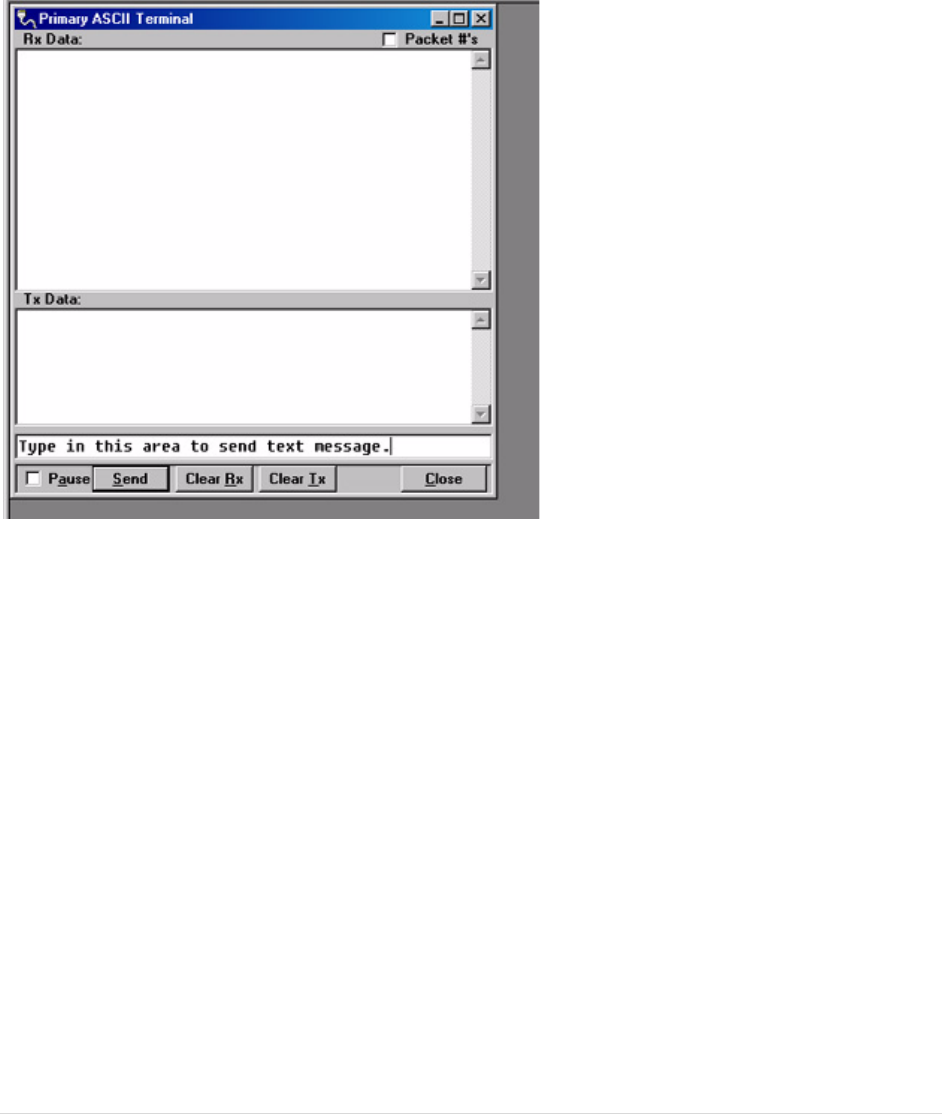
GuardianManual001‐5006‐000Rev059|Page
Underthe“Utilities”menuchoosethe“ASCIITerminal”.Fromthe“ASCIITerminal”screen,choosethe“Primary”
selection.ThiswillopenanASCIIterminalwindowusingtheprimaryCOMportofthecomputer.Thisprocedure
shouldbedoneforbothGUARDIANs.TheASCIITerminalutilityhasprovisionsfortransmittingtheASCIIdata,
displayingreceivedASCIIdataanddisplayingASCIItransmitteddata.Figure2‐23showsthewindowforthePrimary
ASCIITerminal.
Figure2‐23EndtoEndTest:ASCIITerminal
Figure2‐23alsoshowstheareathatisusedtosendanASCIItextmessage.TheASCIIdatamessageistypedinto
thisarea.TheASCIItextmessageisthensentoutthefirstGUARDIANthroughthecomputer’sprimaryportonce
the“Send“buttonisclicked.ThesentASCIImessageisthendisplayedintheTxDataareaoftheASCIITerminal
windowasshowninFigure2‐24.
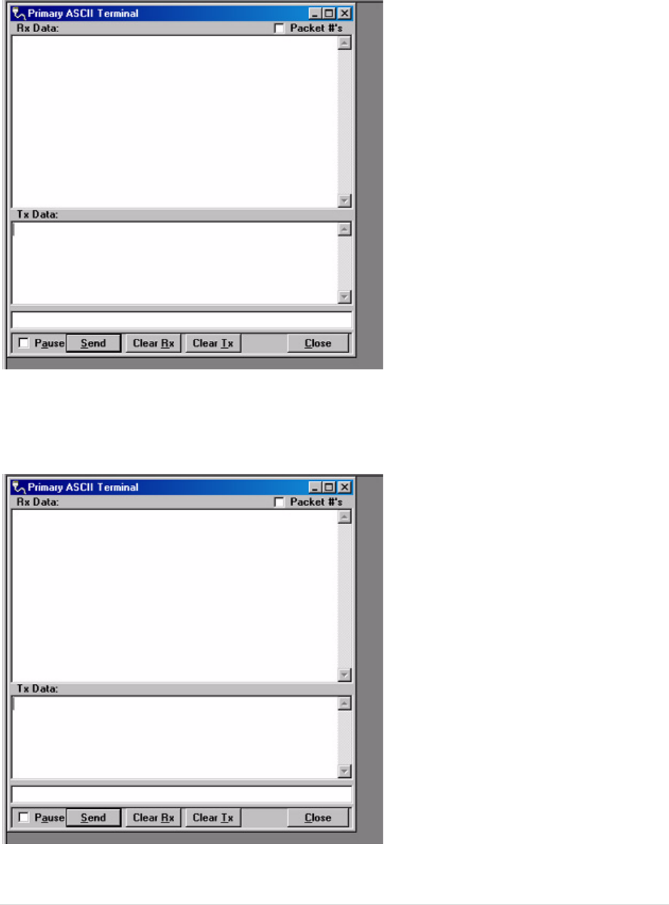
GuardianManual001‐5006‐000Rev060|Page
Figure2‐24EndtoEndTest:Textmessagesent
TheASCIImessageistransmittedtotheotherGUARDIAN.TheASCIIterminalprogramwilldisplaythereceived
ASCIImessageintheRxDataareaasshownFigure2‐25.
Figure2‐25EndtoEndTest:Textmessagereceived
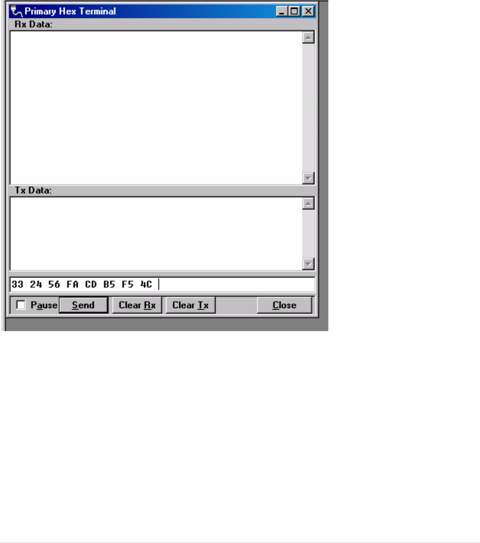
GuardianManual001‐5006‐000Rev061|Page
Ifthemessagewasnotdisplayedastyped,thenaproblemmayexistinthesystem.Checkallparametersand
connectionsinthesystem.Thesignallevelshouldalsobecheckedagain.TheGUARDIAN’sLinkTestutilitycanbe
usedtoverifyacommunicationpath.
ThepreviousprocedurecanalsobeusedwiththeHexTerminalutility.WhentheHexTerminalisused,the
informationisenteredashexcode.Figure2‐26showshowtheinformationwilllookwhenitistypedinandsentin
hex.
Figure2‐26HexTerminal
IntheHexTerminalmode,theprogramwillnottransmitASCIIinformation.Itwillonlyallowvalidhexcharacters.

GuardianManual001‐5006‐000Rev062|Page
6 GUARDIANSPECIFICATIONS
Thesespecificationsaretypicalandsubjecttochangewithoutnotice.
GENERAL VHF UHF 900
Model Numbers
140-5016-50x
140-5026-50x
140-5046-30x
140-5046-400 (ETSI, AS/NZ)
140-5046-50x
140-5046-600 (AS/NZ)
140-5096-50x
Frequency Range (MHz) 136 – 174 MHz
215 – 240 MHz
406.125 – 470.000 MHz
406.125 – 470.000 MHz
450.000 - 511.975 MHz
450.000 - 511.975 MHz
928 – 960 MHz
Frequency Stability 1.0 ppm 1.0 ppm 1.0 ppm
Channel Bandwidth
12.5 kHz
25 kHz
12.5 kHz
25 kHz
12.5 kHz (ETSI, AS/NZ certified)
25 kHz (ETSI, AS/NZ certified)
12.5 kHz
25 kHz
Modes of Operation Simplex, Half-Duplex, Full-Duplex
Frequency Increment 1.25 kHz
Power Source 10-30 VDC, Negative GND
The Guardian is UL approved when powered with a listed Class 2 power supply.
RF Impedance 50 Ω
Operating Temperature -30° to + 60° C
Storage Temperature -40° to + 85° C, 95% non-condensing RH
Operating Humidity 5% to 95% non-condensing RH
Rx Current Drain at 25°C DC Input 10V DC Input 20V DC Input 30V
520 mA (max)
450 mA (typ)
270 mA (max)
240 mA (typ)
190 mA (max)
170 mA (typ)
Tx Current Drain at 25°C Power Out DC Input 10V DC Input 20V DC Input 30V
Max Pwr 5.8 A (max)
3.6 A (typ)
2.5 A (max)
1.8 A (typ)
1.6 A (max)
1.2 A (typ)
30 dBm
(1W)
1.6 A (max)
1.2 A (typ)
0.8 A (max)
0.6 A (typ)
0.6 A (max)
0.4 A (typ)
Cold start 20 seconds
Nominal Dimensions 5.50" W x 2.125” H x 4.25" D (13.97 x 5.40 x 10.8 cm)
Shipping Weight 2.4 lbs. (1.1 Kg)
Mounting Options Mounting plate/pattern & DIN Rail
Fan Output 5VDC, 400mA max.

GuardianManual001‐5006‐000Rev063|Page
TRANSMITTER VHF UHF 900
Tx Frequencies 136 - 174 MHz
215 – 240 MHz
406.125 – 470.000 MHz
450.000 - 511.975 MHz
928 - 960 MHz
Carrier Output Power 1-10 Watts Adjustable 1-10 Watts Adjustable 1-8 Watts Adjustable
Duty Cycle 100% (Power Foldback Allowed for High Temperatures)
Radiated Spurious Emissions Per FCC/Regulatory
Conducted Spurious Emissions Per FCC/Regulatory
Transmitter Stability into VSWR: > 10:1 (Power Foldback Allowed)
RX to TX Time < 2 ms (Standard)
4 ms (ETSI Versions)
Channel Switching Time < 15 ms (Band-End to Band-End)
RECEIVER
Bandwidth
Bit Rate
140-5016-
50x
140-5026-
50x
140-5046-30x
140-5046-50x
140-5096-
50x
Units
RX Frequencies 136 - 174 215 - 240 406.125 – 470.000
450.000 - 511.975
928 - 960 MHz
Data Sensitivity
@ 10-6 Bit Error
Rate (BER)
Typical / Max
12.5 kHz
4.9 kbps
9.6 kbps
dBm
25 kHz
4.8 kbps
9.6 kbps
19.2 kbps
dBm
Adjacent Channel
Rejection (min)
12.5 kHz 60 60 60 60 dB
25 kHz 75 70 75 70 dB
Spurious
Response
Rejection
All > 75 dB dB
Intermodulation
Rejection All > 75 dB dB
TX to RX Time All < 1 ms (Standard)
5 ms (ETSI Versions) ms
Channel
Switching Time All < 15ms (Band-End to Band-End) ms
Receive Input
Power All 17 dBm (50mW) max. dBm

GuardianManual001‐5006‐000Rev064|Page
MODEM/LOGIC
Model 12.5 kHz 25 kHz
Data Rate (Selectable)
140-5016-50x 4800
9600
4800
9600
19200
140-5026-50x 4800
9600
4800
9600
19200
140-5046-30x
4800
9600
4800
9600
19200
140-5046-50x 4800
9600
4800
9600
19200
140-5096-50x 4800
9600
4800
9600
19200
Modulation Type 2FSK
Addressing Serial
SETUP and COM Port
Interface EIA-232F DCE
Data Rate Setup Port: 300 – 19,200 bps (Default: 19.2 Kbps)
Com Port: 300 – 115,200 bps (Default: 9.6 Kbps)
Display
5 Tri-color status LEDs Power, Status, Rx, Tx, RD/TD
Connectors
Antenna Connector TNC female (Tx/Rx), SMA female (Rx) – Full-duplex models only
Serial Setup Port DE-9F
Serial Terminal Server DE-9F
User Interface I/O Right angle, 8 contacts (male)
Power - I/O I/O Right angle, 4 contacts (male)Power Plug
GuardianManual001‐5006‐000Rev065|Page
Diagnostics
Message Elements Temp, Voltage, Local/Remote RSSI, Forward Power, Reverse Power, Message Quality
Domestic and International Certifications
Model Number Frequency
Range FCC IC (DOC)
European Union
EN 300 113
Australia/New
Zealand
140-5016-500 136 – 174 MHz NP4-5016-500 773B-5016500
140-5016-501 136 – 174 MHz NP4-5016-500 773B-5016500
140-5026-502 215 – 240 MHz NP4-5026-502 Pending
140-5026-503 215 – 240 MHz NP4-5026-502 Pending
140-5046-300 406.1 - 470 MHz NP4-5046-300 773B-5046300
140-5046-301 406.1 - 470 MHz NP4-5046-300 773B-5046300
140-5046-400 406.1 - 470 MHz 1588 Pending
140-5046-500 450 - 512 MHz NP4-5046-300 773B-5046300
140-5046-501 450 - 512 MHz NP4-5046-300 773B-5046300
140-5046-600 450 - 512 MHz Pending
140-5096-500 928 - 960 MHz NP4-5096-500 773B-5096500
140-5096-501 928 - 960 MHz NP4-5096-500 773B-5096500
UL Certification
All modelsUL approved when powered with a listed Class 2 source.

GuardianManual001‐5006‐000Rev066|Page
7 PRODUCTWARRANTY
PRODUCTWARRANTY
CalAmpwarrantstotheoriginalpurchaserforuse("Buyer")thatdatatelemetryproductsmanufacturedbyDRL
("Products")arefreefromdefectsinmaterialandworkmanshipandwillconformtoDRL'spublishedtechnical
specificationsforaperiodof,exceptasnotedbelow,one(1)yearfromthedateofshipmenttoBuyer.DRLmakesno
warrantywithrespecttoanyequipmentnotmanufacturedbyDRL,andanysuchequipmentshallcarrytheoriginal
equipmentmanufacturer'swarrantyonly.DRLfurthermakesnowarrantyastoandspecificallydisclaimsliabilityfor,
availability,range,coverage,gradeofserviceoroperationoftherepeatersystemprovidedbythecarrierorrepeater
operator.Anyreturnshippingchargesforthirdpartyequipmenttotheirrespectiverepairfacilitiesarechargeableand
willbepassedontotheBuyer.
IfanyProductfailstomeetthewarrantysetforthaboveduringtheapplicablewarrantyperiodandisreturnedtoa
locationdesignatedbyDRL.DRL,atitsoption,shalleitherrepairorreplacesuchdefectiveProduct,directlyorthrough
anauthorizedserviceagent,withinthirty(30)daysofreceiptofsame.NoProductsmaybereturnedwithoutprior
authorizationfromDRL.AnyrepairedorreplacedProductsshallbewarrantedfortheremainderoftheoriginal
warrantyperiod.Buyershallpayallshippingcharges,handlingcharges,feesanddutiesforreturningdefectiveProducts
toDRLorDRL'sauthorizedserviceagent.DRLwillpaythereturnshippingchargesiftheProductisrepairedorreplaced
underwarranty,exclusiveoffeesandduties.RepairorreplacementofdefectiveProductsassetforthinthisparagraph
fulfillsanyandallwarrantyobligationsonthepartofDRL.
ThiswarrantyisvoidandDRLshallnotbeobligatedtoreplaceorrepairanyProductsif(i)theProducthasbeenusedin
otherthanitsnormalandcustomarymanner;(ii)theProducthasbeensubjecttomisuse,accident,neglectordamage
orhasbeenusedotherthanwithDRLapprovedaccessoriesandequipment;(iii)unauthorizedalterationorrepairs
havebeenmadeorunapprovedpartshavebeenusedinorwiththeProduct;or(iv)BuyerfailedtonotifyDRLorDRL's
authorizedserviceagentofthedefectduringtheapplicablewarrantyperiod.DRListhefinalarbiterofsuchclaims.
THEAFORESAIDWARRANTIESAREINLIEUOFALLOTHERWARRANTIES,EXPRESSEDANDIMPLIED,INCLUDINGBUT
NOTLIMITEDTO,ANYIMPLIEDWARRANTYOFMERCHANTABILITYORFITNESSFORAPARTICULARPURPOSE.DRLAND
BUYERAGREETHATBUYER'SEXCLUSIVEREMEDYFORANYBREACHOFANYOFSAIDWARRANTIESITASSETFORTH
ABOVE.BUYERAGREESTHATINNOEVENTSHALLDRLBELIABLEFORINCIDENTAL,CONSEQUENTIAL,SPECIAL,
INDIRECTOREXEMPLARYDAMAGESWHETHERONTHEBASISOFNEGLIGENCE,STRICTLIABILITYOROTHERWISE.The
purposeoftheexclusiveremediessetforthaboveshallbetoprovideBuyerwithrepairorreplacementofnon‐
complyingProductsinthemannerprovidedabove.Theseexclusiveremediesshallnotbedeemedtohavefailedof
theiressentialpurposesolongasDRLiswillingandabletorepairorreplacenon‐complyingProductsinthemannerset
forthabove.
ThiswarrantyappliestoallProductssoldworldwide.Somestatesdonotallowlimitationsonimpliedwarrantiessothe
abovelimitationsmaynotbeapplicable.Youmayalsohaveotherrights,whichvaryfromstatetostate.
EXCEPTIONS
THIRTYDAY: Tuningandadjustmentoftelemetryradios
NOWARRANTY: Fuses,lampsandotherexpendableparts

GuardianManual001‐5006‐000Rev067|Page
ABOUTCALAMP
CalAmpisaleadingproviderofwirelesscommunicationsproductsthatenableanytime/anywhereaccesstocritical
information,dataandentertainmentcontent.Withcomprehensivecapabilitiesrangingfromproductdesignand
developmentthroughvolumeproduction,CalAmpdeliverscost‐effectivehighqualitysolutionstoabroadarrayof
customersandendmarkets.CalAmpistheleadingsupplierofDirectBroadcastSatellite(DBS)outdoorcustomer
premiseequipmenttotheU.S.satellitetelevisionmarket.TheCompanyalsoprovideswirelessdatacommunication
solutionsforthetelemetryandassettrackingmarkets,privatewirelessnetworks,publicsafetycommunicationsand
criticalinfrastructureandprocesscontrolapplications.Foradditionalinformation,pleasevisittheCompany’swebsite
atwww.calamp.com.