CalAmp Wireless Networks 5028504 VIPER SC+ 200 VHF 215-240MHZ User Manual Rev D
CalAmp Wireless Networks Corporation VIPER SC+ 200 VHF 215-240MHZ Users Manual Rev D
UserManual.wiki
>
CalAmp Wireless Networks
>
5028504 User Manual
Users Manual Rev D
Navigation menu
Upload a User Manual
Namespaces
Wiki Guide
HTML
PDF
Info
Views
User Manual
Discussion / Help
Navigation
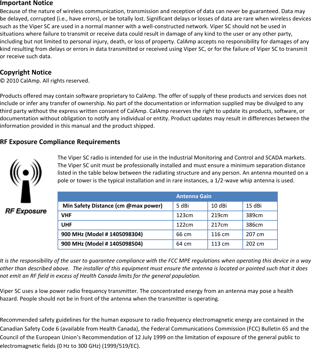
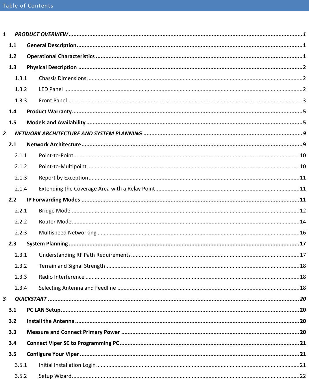
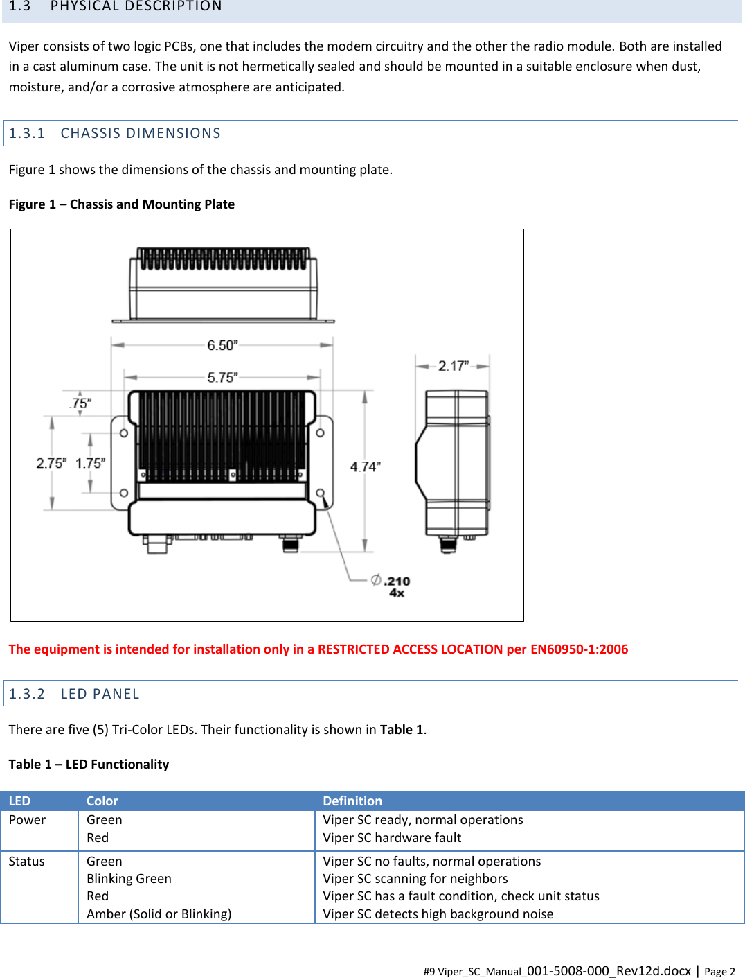


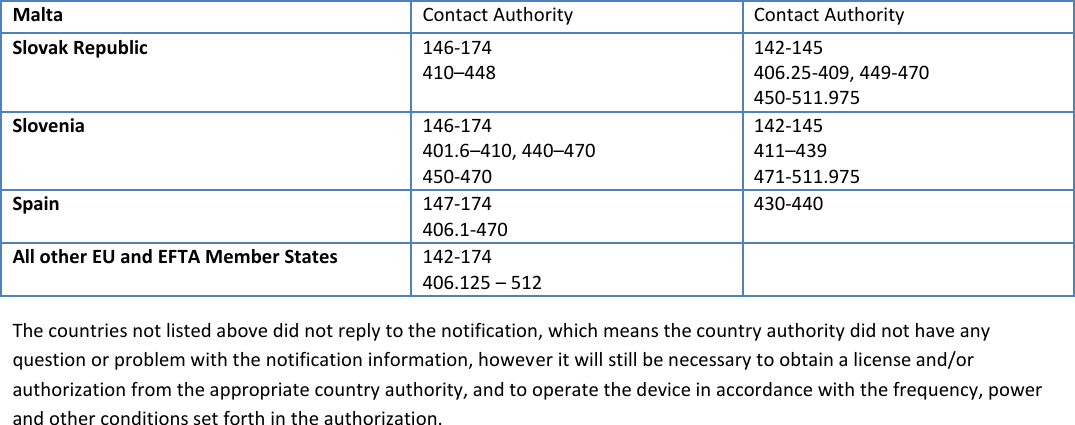
![DECLARATION OF CONFORMITY FOR MODELS # 140-5018-60x, 140-5048-40x, and 140-5048-60x The Viper radio is tested to and conforms with the essential requirements for protection of health and the safety of the user and any other person and Electromagnetic Compatibility, as included in following standards: Standard Issue Date EN 60950-1 EN 301 489-1 EN 301 489-5 2006 (with Amendment A11: 2009 + A1: 2010 2008-04 2002-08 and is tested to and conforms with the essential radio test suites so that it effectively uses the frequency spectrum allocated to terrestrial/space radio communication and orbital resources so to as to avoid harmful interference, as included in following standards: Standard Issue Date EN 300 113-1/-2 2009-11 and therefore complies with the essential requirements and provisions of the Directive 1999/5/EC of the European Parliament and of the council of March 9, 1999 on Radio equipment and Telecommunications Terminal Equipment and the mutual recognition of their conformity and with the provisions of Annex IV (Conformity Assessment procedure referred to in article 10). This device is a data transceiver intended for commercial and industrial use in all EU and EFTA member states. Česky [Czech] CalAmp tímto prohlašuje, že tento rádio je ve shodě se základními požadavky a dalšími příslušnými ustanoveními směrnice 1999/5/ES. Dansk [Danish] Undertegnede CalAmp erklærer herved, at følgende udstyr radio overholder de væsentlige krav og øvrige relevante krav i direktiv 1999/5/EF. Deutsch [German] Hiermit erklärt CalAmp, dass sich das Gerät radio in Übereinstimmung mit den grundlegenden Anforderungen und den übrigen einschlägigen Bestimmungen der Richtlinie 1999/5/EG befindet. Eesti [Estonian] Käesolevaga kinnitab CalAmp seadme raadio vastavust direktiivi 1999/5/EÜ põhinõuetele ja nimetatud direktiivist tulenevatele teistele asjakohastele sätetele. English Hereby, CalAmp, declares that this radio is in compliance with the essential requirements and other relevant provisions of Directive 1999/5/EC. Español [Spanish] Por medio de la presente CalAmp declara que el radio cumple con los requisitos esenciales y cualesquiera otras disposiciones aplicables o exigibles de la Directiva 1999/5/CE. Ελληνική [Greek] ΜΕ ΤΗΝ ΠΑΡΟΥΣΑ CalAmp ΔΗΛΩΝΕΙ ΟΤΙ ΡΑΔΙΌΦΩΝΟ ΣΥΜΜΟΡΦΩΝΕΤΑΙ ΠΡΟΣ ΤΙΣ ΟΥΣΙΩΔΕΙΣ ΑΠΑΙΤΗΣΕΙΣ ΚΑΙ ΤΙΣ ΛΟΙΠΕΣ ΣΧΕΤΙΚΕΣ ΔΙΑΤΑΞΕΙΣ ΤΗΣ ΟΔΗΓΙΑΣ 1999/5/ΕΚ. Français [French] Par la présente CalAmp déclare que l'appareil radio est conforme aux exigences essentielles et aux autres dispositions pertinentes de la directive 1999/5/CE. Italiano [Italian] Con la presente CalAmp dichiara che questo radio è conforme ai requisiti essenziali ed alle altre disposizioni pertinenti stabilite dalla direttiva 1999/5/CE. Latviski [Latvian] Ar šo CalAmp deklarē, ka radio atbilst Direktīvas 1999/5/EK būtiskajām prasībām un citiem ar to saistītajiem noteikumiem. Lietuvių [Lithuanian] Šiuo CalAmp deklaruoja, kad šis radijo atitinka esminius reikalavimus ir kitas 1999/5/EB Direktyvos nuostatas. Nederlands [Dutch] Hierbij verklaart CalAmp dat het toestel radio in overeenstemming is met de essentiële eisen en de andere relevante bepalingen van richtlijn 1999/5/EG. Malti [Maltese] Hawnhekk, CalAmp , jiddikjara li dan tar-radju jikkonforma mal-ħtiġijiet essenzjali u ma](https://usermanual.wiki/CalAmp-Wireless-Networks/5028504/User-Guide-2052796-Page-110.png)
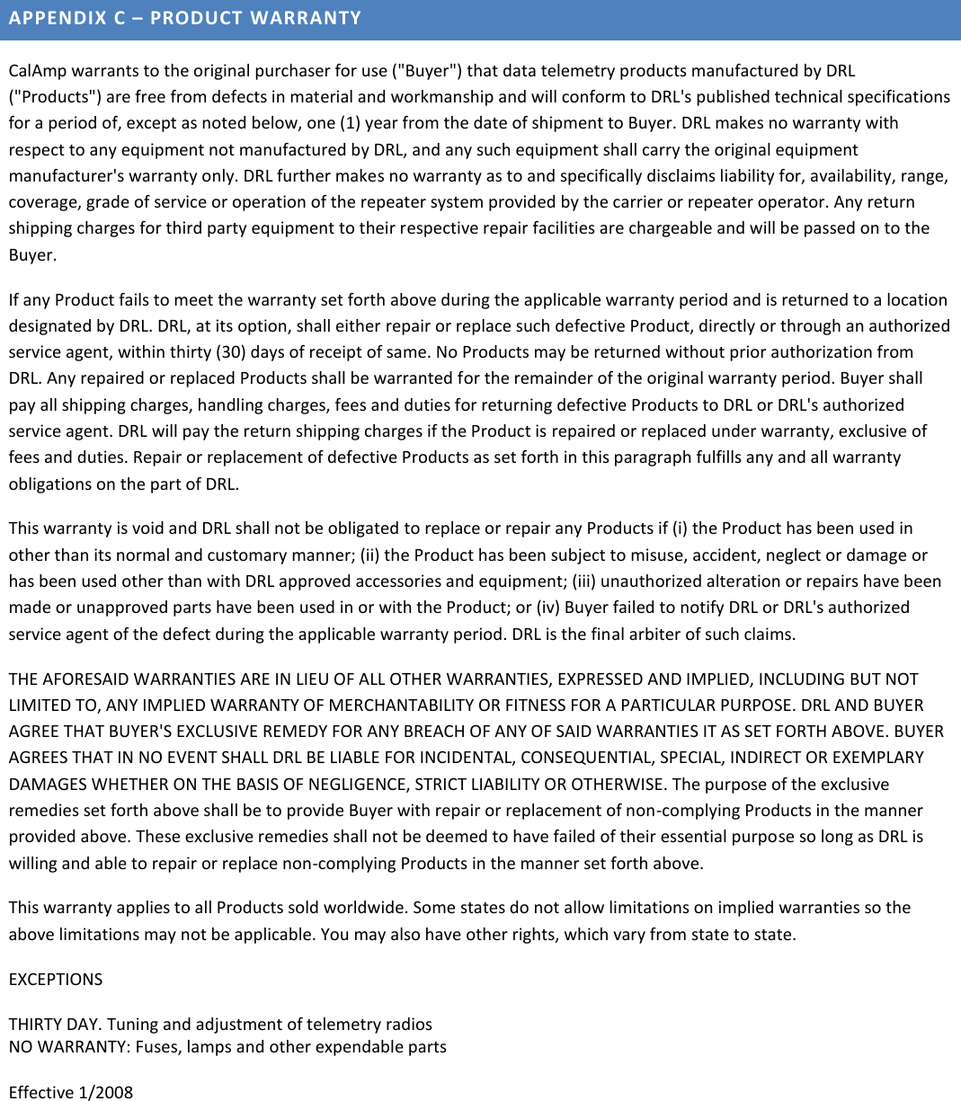
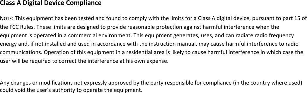
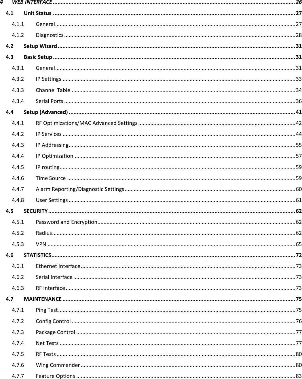
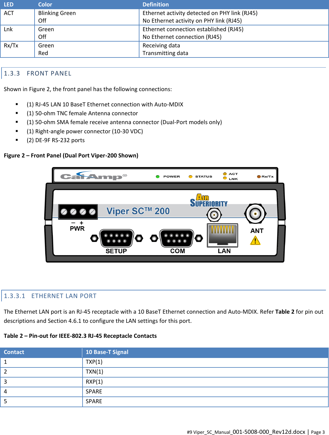
![provvedimenti oħrajn relevanti li hemm fid-Dirrettiva 1999/5/EC. Magyar [Hungarian] Alulírott, CalAmp nyilatkozom, hogy a rádió megfelel a vonatkozó alapvetõ követelményeknek és az 1999/5/EC irányelv egyéb elõírásainak. Polski [Polish] Niniejszym CalAmp oświadcza, że radio jest zgodny z zasadniczymi wymogami oraz pozostałymi stosownymi postanowieniami Dyrektywy 1999/5/EC. Português [Portuguese] CalAmp declara que este rádio está conforme com os requisitos essenciais e outras disposições da Directiva 1999/5/CE. Slovensko [Slovenian] CalAmp izjavlja, da je ta radio v skladu z bistvenimi zahtevami in ostalimi relevantnimi določili direktive 1999/5/ES. Slovensky [Slovak] CalAmp týmto vyhlasuje, že rádio spĺňa základné požiadavky a všetky príslušné ustanovenia Smernice 1999/5/ES. Suomi [Finnish] CalAmp vakuuttaa täten että radio tyyppinen laite on direktiivin 1999/5/EY oleellisten vaatimusten ja sitä koskevien direktiivin muiden ehtojen mukainen. Svenska [Swedish] Härmed intygar CalAmp att denna radio står I överensstämmelse med de väsentliga egenskapskrav och övriga relevanta bestämmelser som framgår av direktiv 1999/5/EG. Íslenska [Icelandic] Hér með lýsir CalAmp yfir því að útvarp er í samræmi við grunnkröfur og aðrar kröfur, sem gerðar eru í tilskipun 1999/5/EC. Norsk [Norwegian] CalAmp erklærer herved at utstyret radio er i samsvar med de grunnleggende krav og øvrige relevante krav i direktiv 1999/5/EF. EU and EFTA Member States’ Acceptable Frequency Table Country Acceptable Frequencies Prohibited Frequencies Belgium 146-174, 406.1–430 or 440-470 450–470 470–512 Bulgaria None All Denmark 406.125-470, 450-511.975 136-174 Estonia None All France Contact Authority Contact Authority Germany Contact Authority Contact Authority Greece 142-174 421–449 406.1250-420 450-511.975 Hungary 142-174 406.125-470 450-511.975 Contact Authority Italy 142-174 Contact Authority Latvia 142-174 406.125-470 450-470 470-511.975 Lithuania 406.125–430 440–470 136-146 430–440 470-512 Luxembourg 146-156.5125 156.5375-156.7625 156.8375-169.4 169.825-174 406.1-430 440-470 142-145 431-439 471-511.975](https://usermanual.wiki/CalAmp-Wireless-Networks/5028504/User-Guide-2052796-Page-111.png)