CalAmp Wireless Networks 5098-500 ViPR Narrowband IP Modem User Manual 9 ViPR Rev2
CalAmp Wireless Networks Corporation ViPR Narrowband IP Modem 9 ViPR Rev2
UserManual.wiki
>
CalAmp Wireless Networks
>
5098 500 User Manual
Users Manual
Navigation menu
Upload a User Manual
Namespaces
Wiki Guide
HTML
PDF
Info
Views
User Manual
Discussion / Help
Navigation
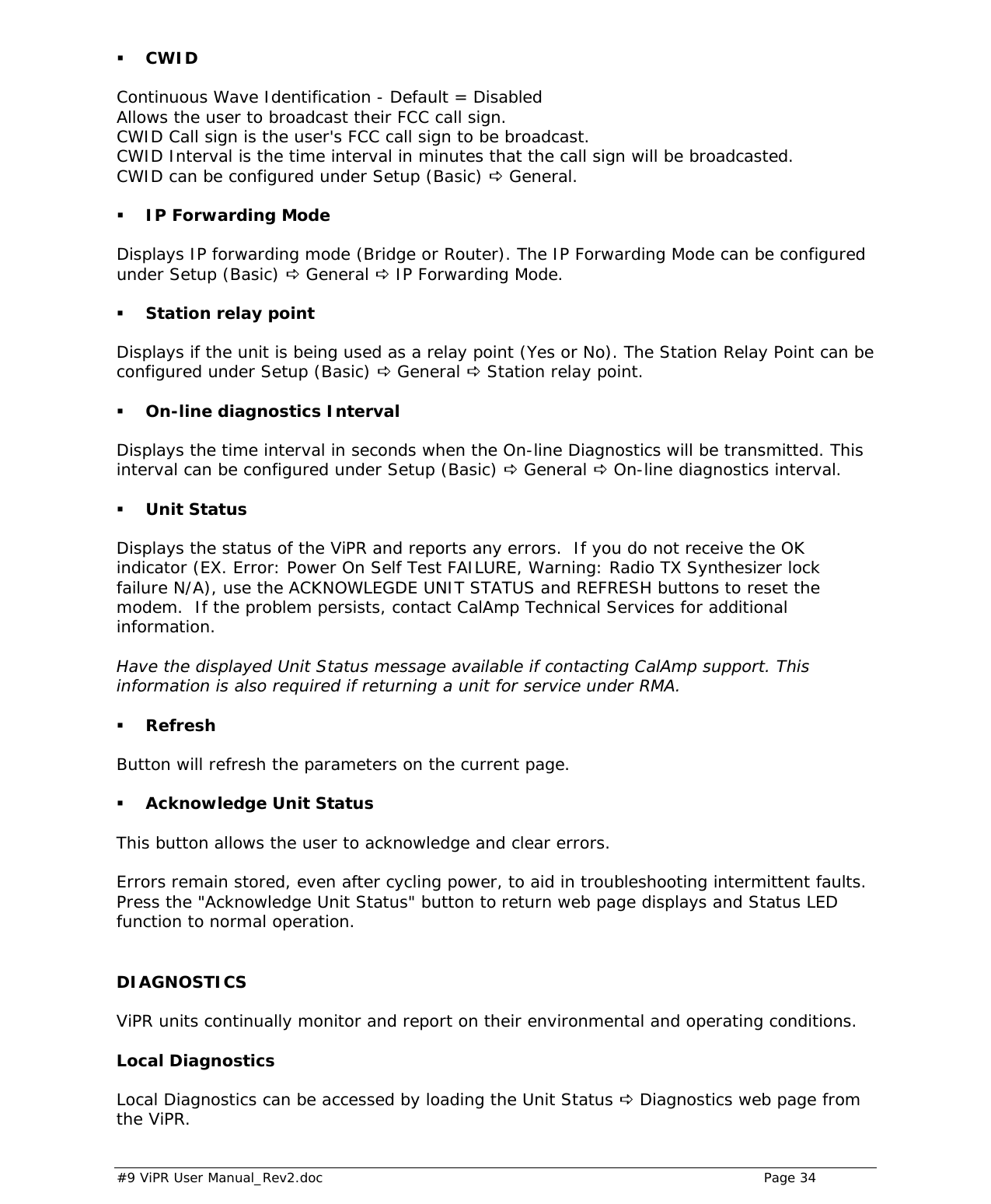
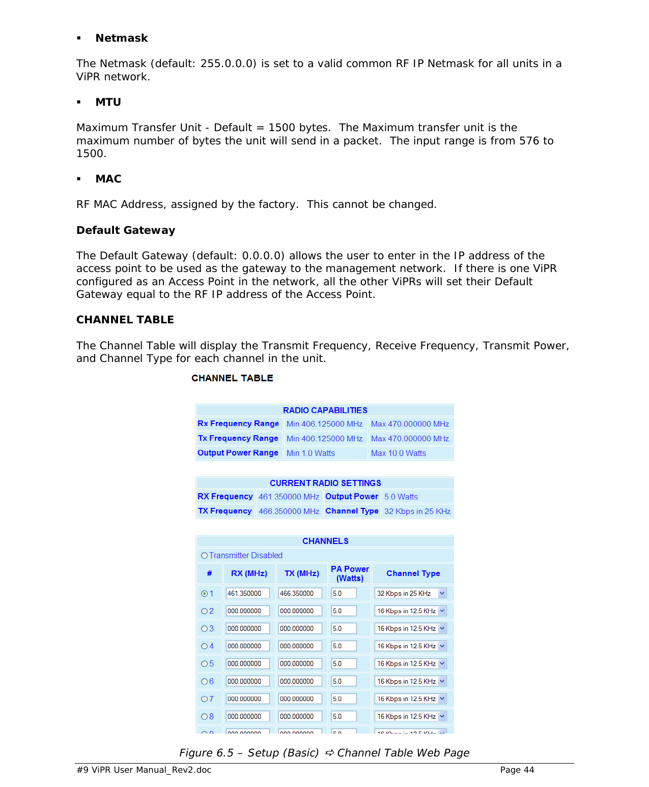
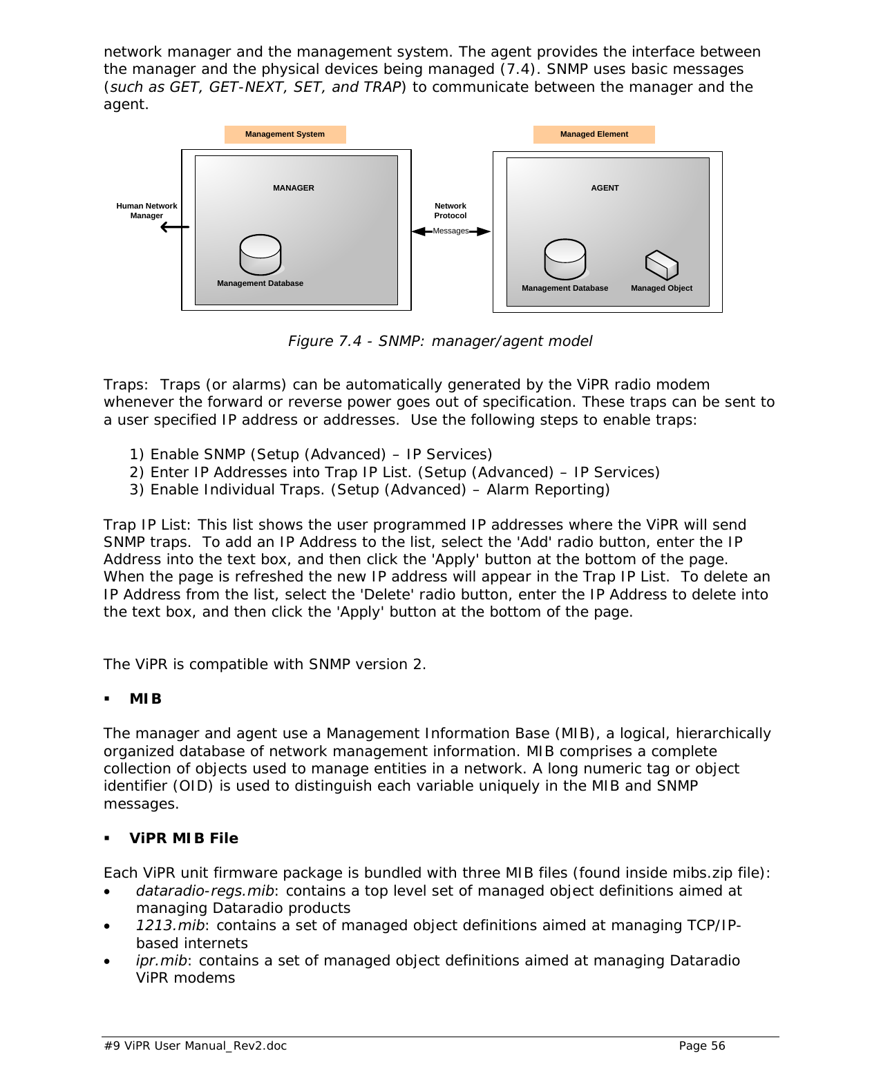
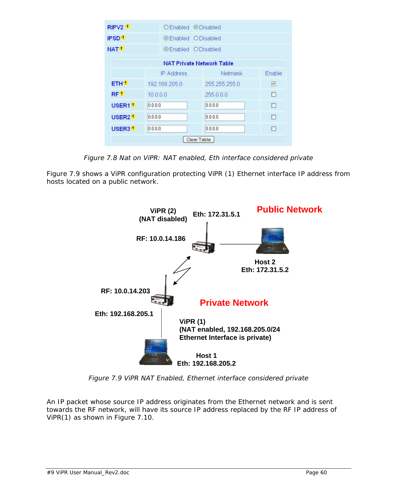
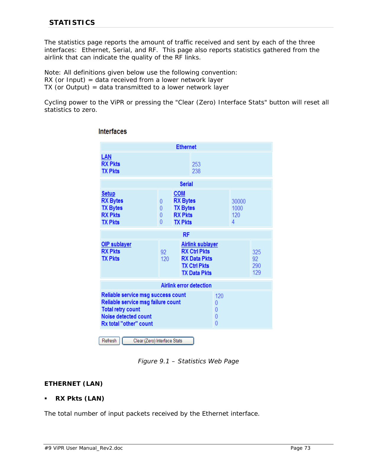
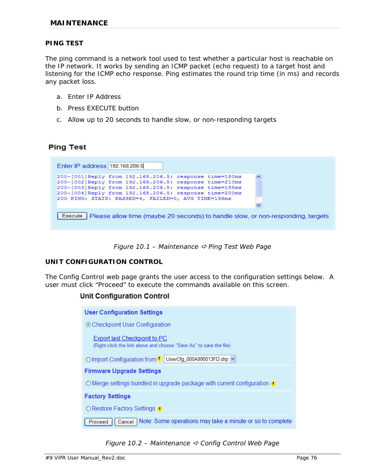
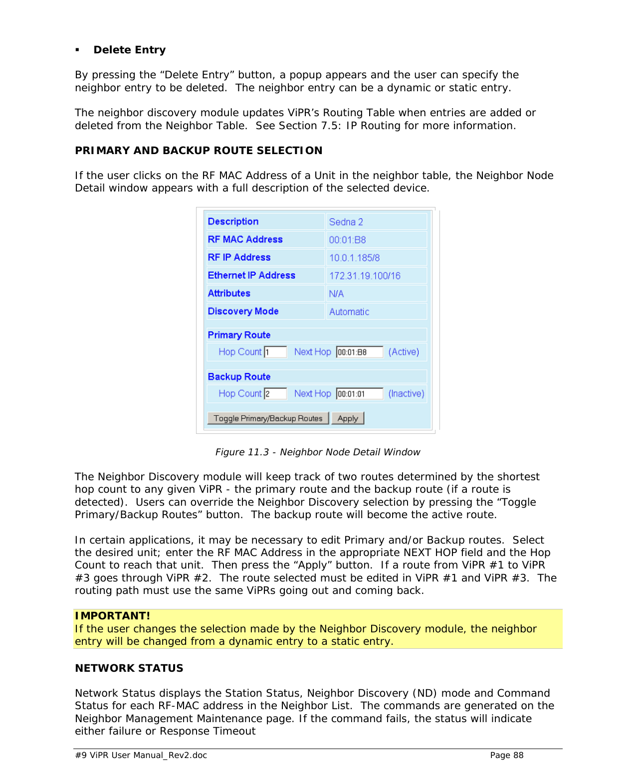
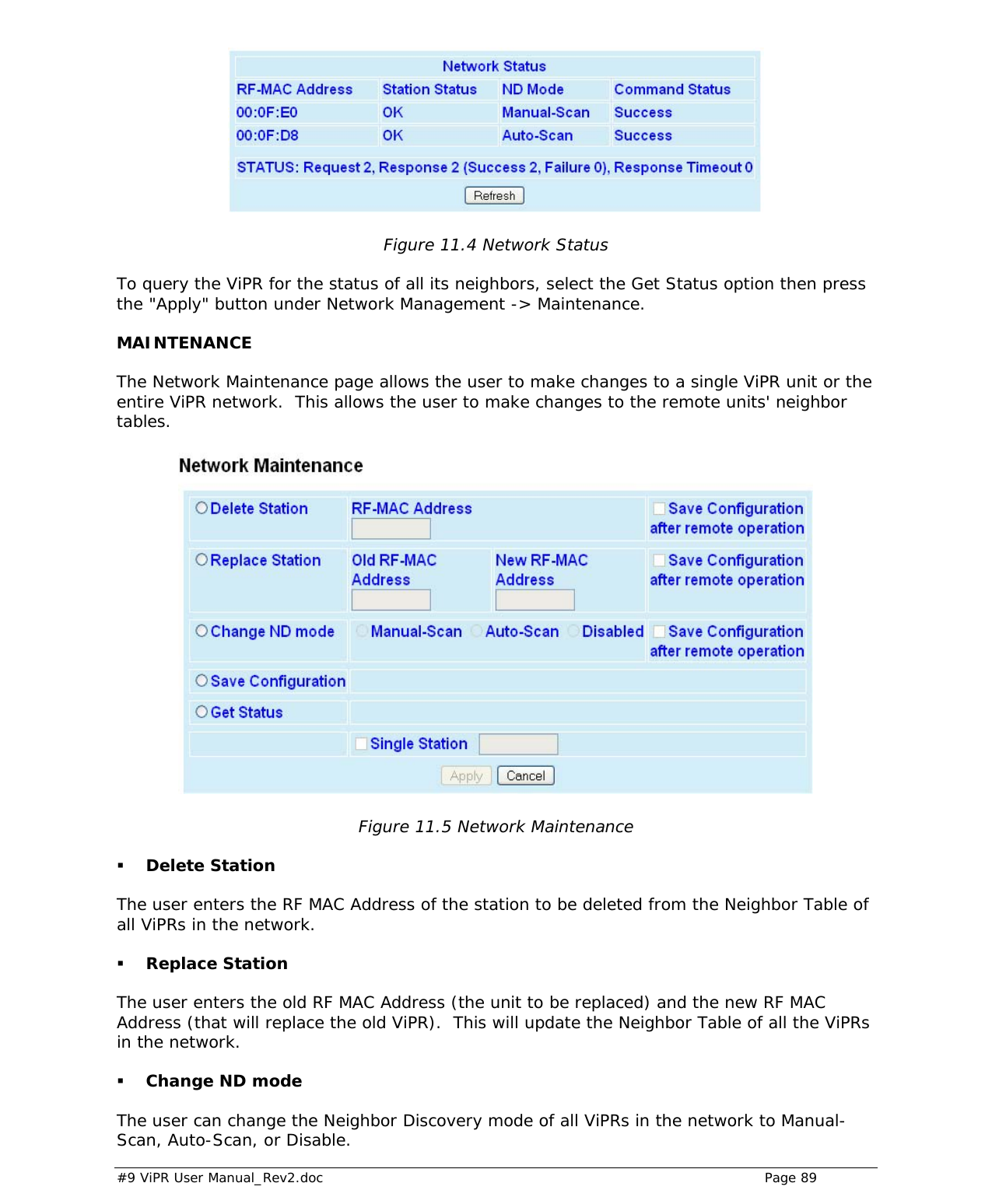
![#9 ViPR User Manual_Rev2.doc Page 35 Figure 5.2 – Unit Status D Diagnostics Web Page Date and time Displays the time and date. To set the time, an SNTP server must be setup under Setup (Advanced) D Time Source. The SNTP server must also be accessible via the user’s LAN or Internet connection. Time since reset Displays the amount of time since the unit was last reset. [DD,HH,MM,SS], Days, Hours, Minutes, Seconds Modem Firmware Version Displays the modem firmware version of the unit. Radio Firmware Version Displays the radio firmware version of the unit. RSSI from RF-MAC Displays the Received Signal Strength Indication (RSSI) from the unit with the MAC address displayed. The RSSI displayed range is from approximately -50 dBm to -120 dBm. At signal strengths greater than -50 dBm, the radio will still operate but will not display an accurate RSSI value. DC Input Voltage Displays the DC Input Voltage for the unit. TX Frequency Displays the current operating transmit frequency for the active channel. Setup (Basic) D Channel Table D TX](https://usermanual.wiki/CalAmp-Wireless-Networks/5098-500/User-Guide-1122286-Page-35.png)