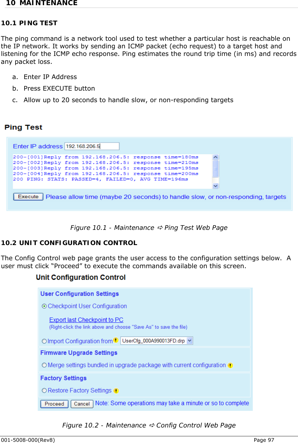
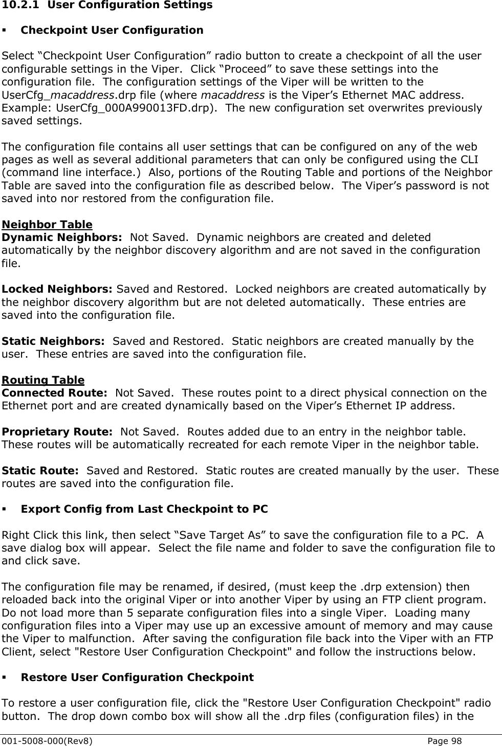
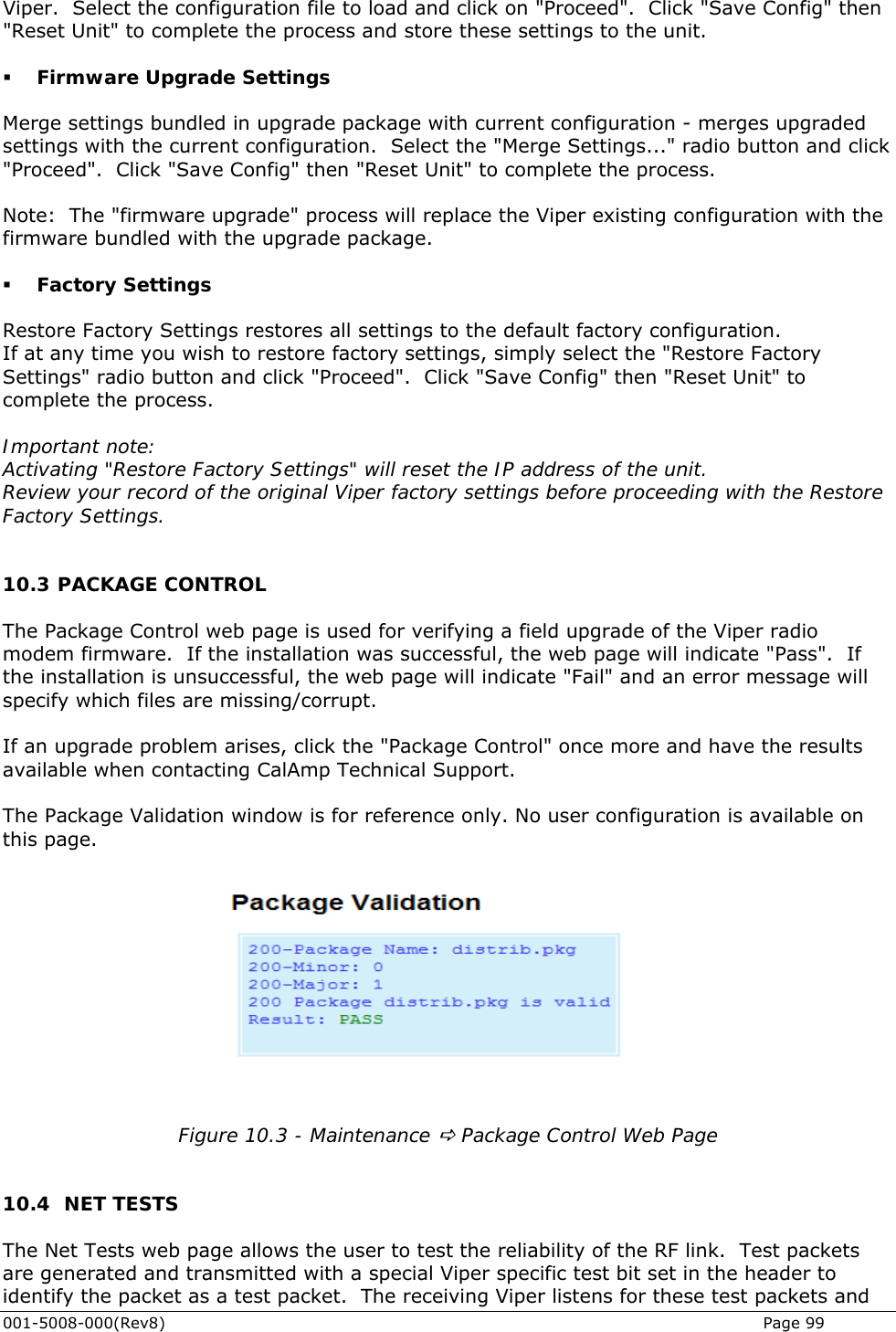
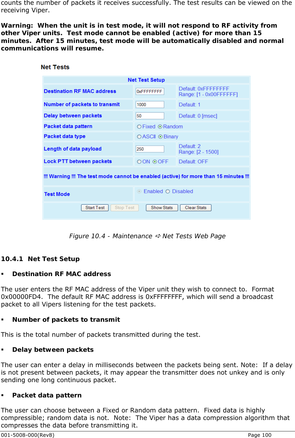
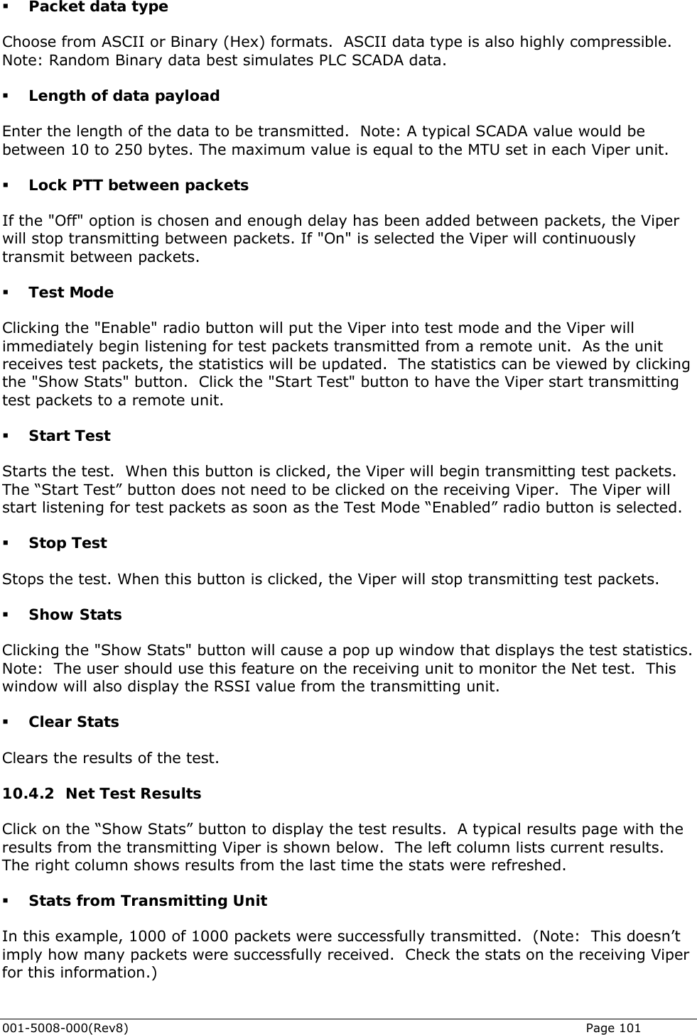
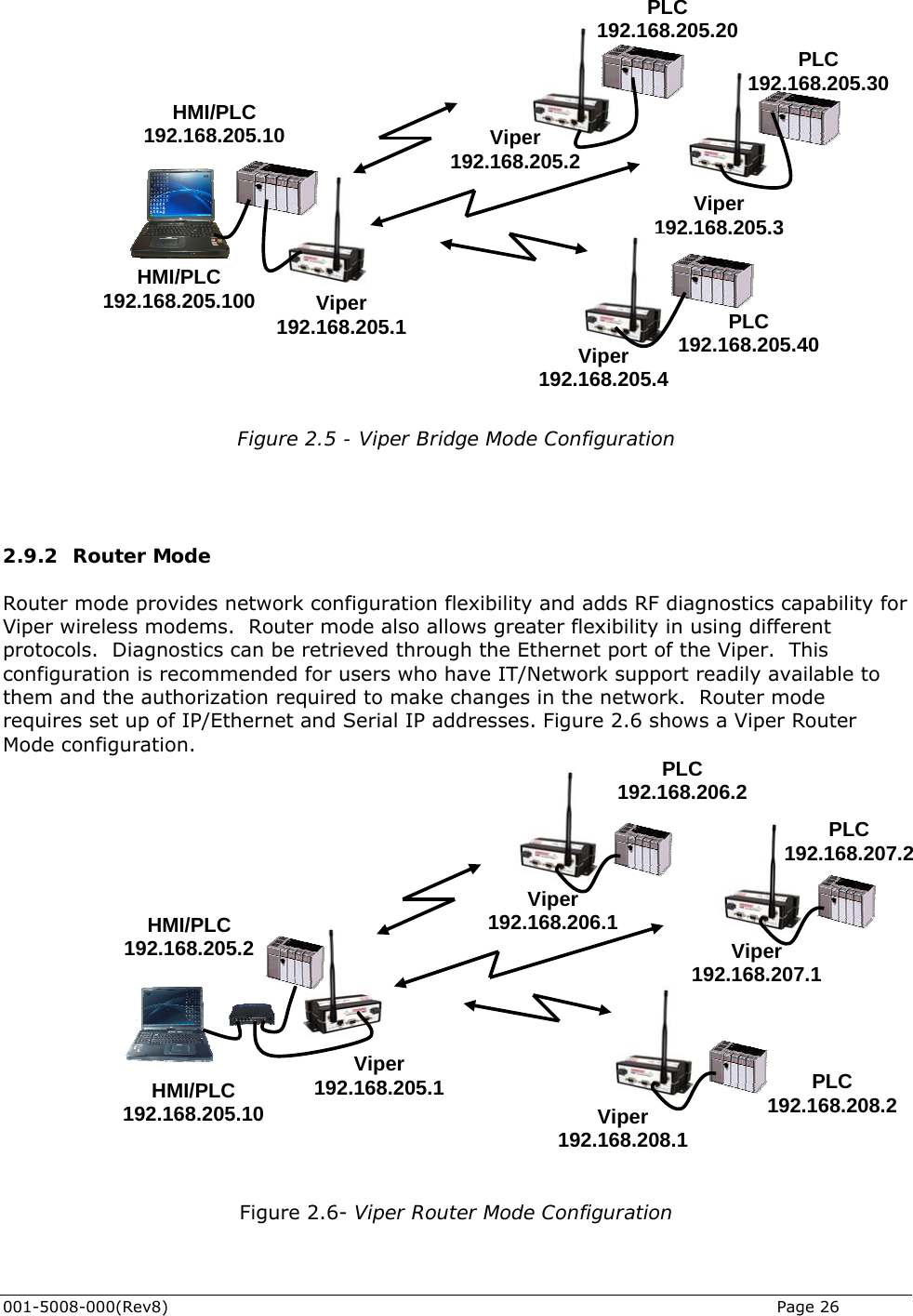
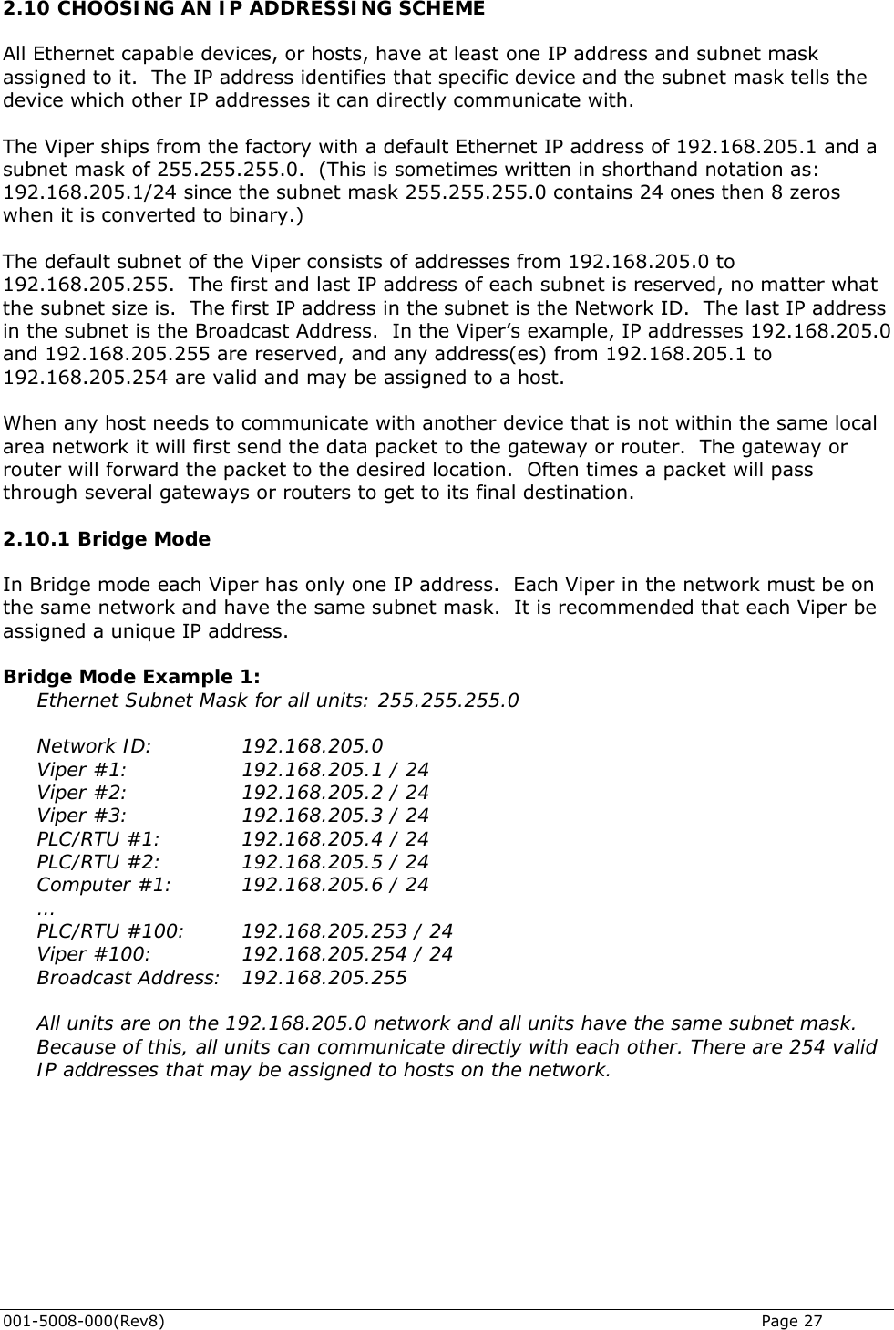
CalAmp Wireless Networks 5098-502 ViPR Narrowband IP Modem User Manual 1
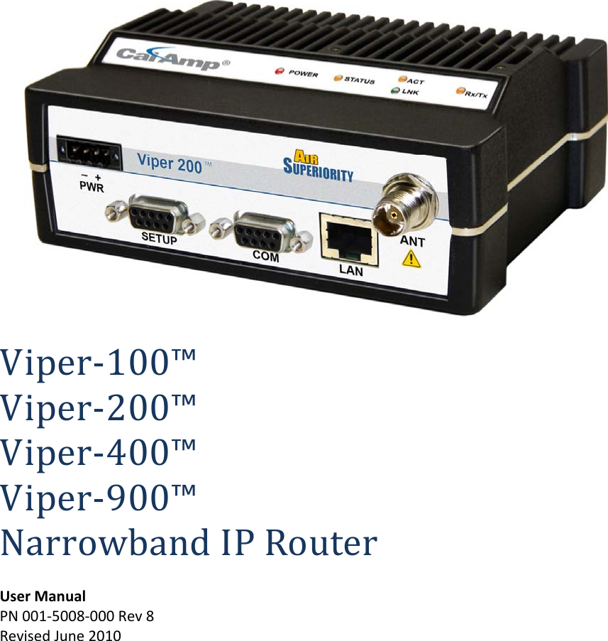
CalAmp Wireless Networks Corporation ViPR Narrowband IP Modem 1
UserManual.wiki
>
CalAmp Wireless Networks
>
5098 502 User Manual
User Manual
Navigation menu
Upload a User Manual
Namespaces
Wiki Guide
HTML
PDF
Info
Views
User Manual
Discussion / Help
Navigation
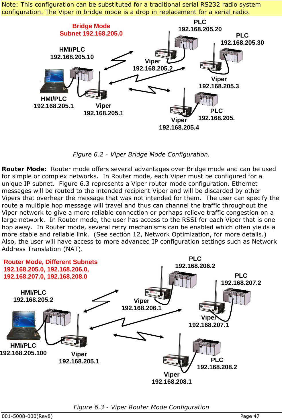
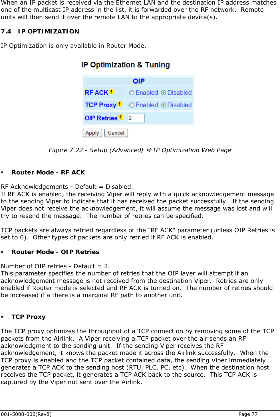
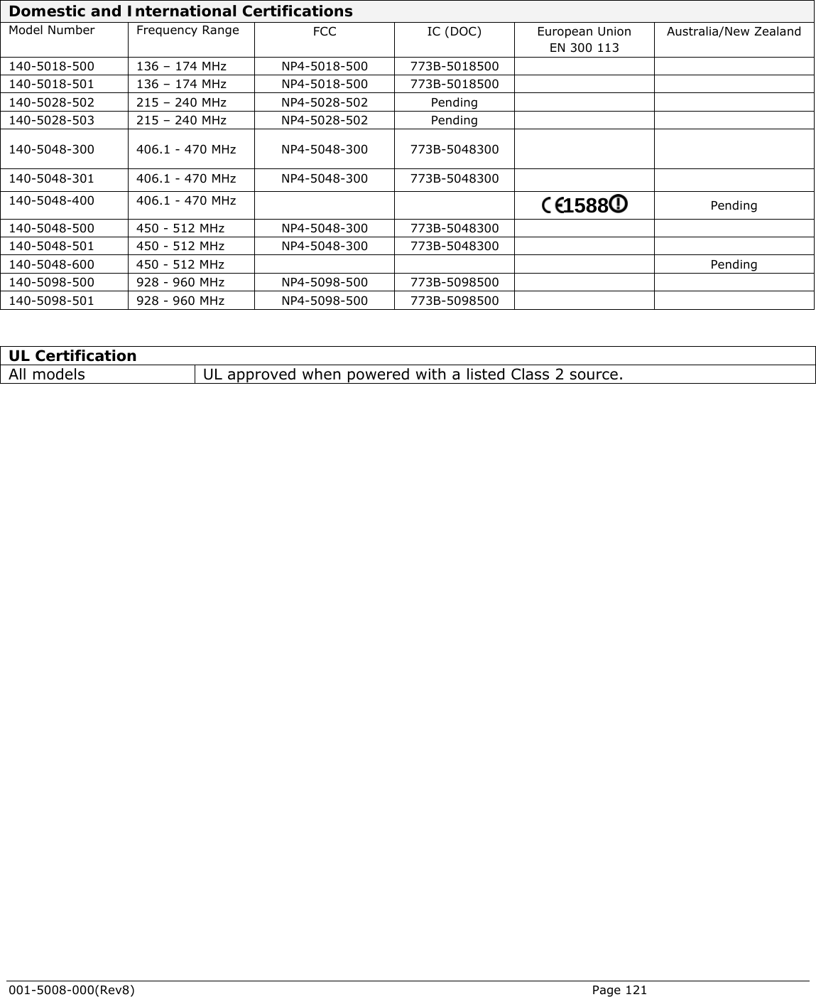
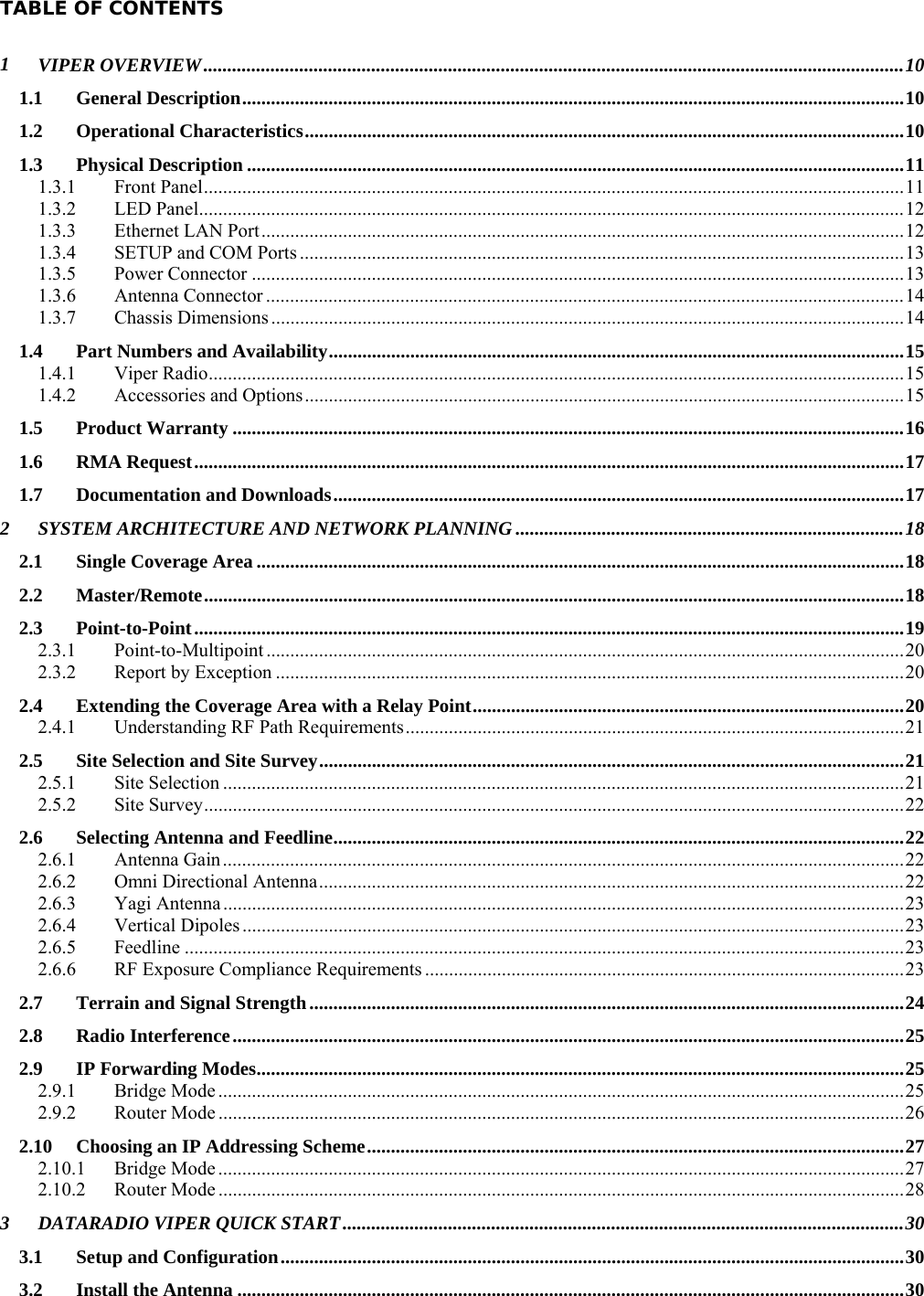
![REGULATORY CERTIFICATIONS The Viper radio is available in several different models each with unique frequency bands. Each model of Viper may have different regulatory approval as shown in the table below. UL Certification All models UL approved when powered with a listed Class 2 source. DECLARATION OF CONFORMITY FOR MODEL # 140-5048-400 This device (Viper model #140-5048-400) is a data transceiver intended for commercial and industrial use in all EU and EFTA member states. Česky [Czech] CalAmp tímto prohlašuje, že tento rádio je ve shodě se základními požadavky a dalšími příslušnými ustanoveními směrnice 1999/5/ES. Dansk [Danish] Undertegnede CalAmp erklærer herved, at følgende udstyr radio overholder de væsentlige krav og øvrige relevante krav i direktiv 1999/5/EF. Deutsch [German] Hiermit erklärt CalAmp, dass sich das Gerät radio in Übereinstimmung mit den grundlegenden Anforderungen und den übrigen einschlägigen Bestimmungen der Richtlinie 1999/5/EG befindet. Eesti [Estonian] Käesolevaga kinnitab CalAmp seadme raadio vastavust direktiivi 1999/5/EÜ põhinõuetele ja nimetatud direktiivist tulenevatele teistele asjakohastele sätetele. English Hereby, CalAmp, declares that this radio is in compliance with the essential requirements and other relevant provisions of Directive 1999/5/EC. Español [Spanish] Por medio de la presente CalAmp declara que el radio cumple con los requisitos esenciales y cualesquiera otras disposiciones aplicables o exigibles de la Directiva 1999/5/CE. Ελληνική [Greek] ΜΕ ΤΗΝ ΠΑΡΟΥΣΑ CalAmp ΔΗΛΩΝΕΙ ΟΤΙ ΡΑΔΙΌΦΩΝΟ ΣΥΜΜΟΡΦΩΝΕΤΑΙ ΠΡΟΣ ΤΙΣ ΟΥΣΙΩΔΕΙΣ ΑΠΑΙΤΗΣΕΙΣ ΚΑΙ ΤΙΣ ΛΟΙΠΕΣ ΣΧΕΤΙΚΕΣ ΔΙΑΤΑΞΕΙΣ ΤΗΣ ΟΔΗΓΙΑΣ 1999/5/ΕΚ. Français [French] Par la présente CalAmp déclare que l'appareil radio est conforme aux exigences essentielles et aux autres dispositions pertinentes de la directive 1999/5/CE. Certifications Model Number Frequency Range FCC IC (DOC) European Union EN 300 113 Australia/New Zealand 140-5018-500 136 – 174 MHz NP4-5018-500 773B-5018500 140-5018-501 136 – 174 MHz NP4-5018-500 773B-5018500 140-5028-502 215 – 240 MHz NP4-5028-502 Pending 140-5028-503 215 – 240 MHz NP4-5028-502 Pending 140-5048-300 406.1 - 470 MHz NP4-5048-300 773B-5048300 140-5048-301 406.1 - 470 MHz NP4-5048-300 773B-5048300 140-5048-400 406.1 - 470 MHz 1588 Pending 140-5048-500 450 - 512 MHz NP4-5048-300 773B-5048300 140-5048-501 450 - 512 MHz NP4-5048-300 773B-5048300 140-5048-600 450 - 512 MHz Pending 140-5098-500 928 - 960 MHz NP4-5098-500 773B-5098500 140-5098-501 928 - 960 MHz NP4-5098-500 773B-5098500](https://usermanual.wiki/CalAmp-Wireless-Networks/5098-502/User-Guide-1328627-Page-4.png)
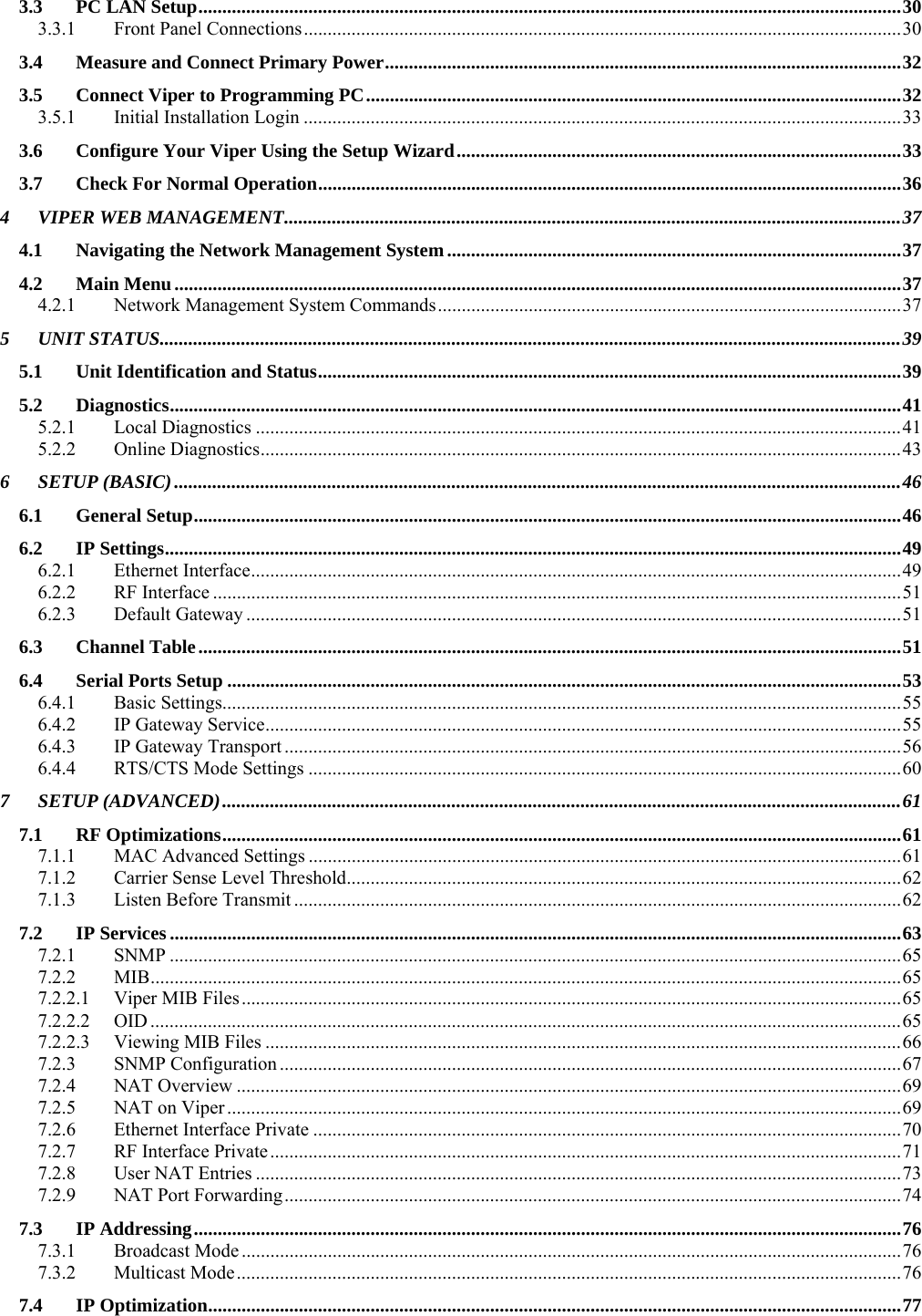
![Italiano [Italian] Con la presente CalAmp dichiara che questo radio è conforme ai requisiti essenziali ed alle altre disposizioni pertinenti stabilite dalla direttiva 1999/5/CE. Latviski [Latvian] Ar šo CalAmp deklarē, ka radio atbilst Direktīvas 1999/5/EK būtiskajām prasībām un citiem ar to saistītajiem noteikumiem. Lietuvių [Lithuanian] Šiuo CalAmp deklaruoja, kad šis radijo atitinka esminius reikalavimus ir kitas 1999/5/EB Direktyvos nuostatas. Nederlands [Dutch] Hierbij verklaart CalAmp dat het toestel radio in overeenstemming is met de essentiële eisen en de andere relevante bepalingen van richtlijn 1999/5/EG. Malti [Maltese] Hawnhekk, CalAmp , jiddikjara li dan tar-radju jikkonforma mal-ħtiġijiet essenzjali u ma provvedimenti oħrajn relevanti li hemm fid-Dirrettiva 1999/5/EC. Magyar [Hungarian] Alulírott, CalAmp nyilatkozom, hogy a rádió megfelel a vonatkozó alapvetõ követelményeknek és az 1999/5/EC irányelv egyéb elõírásainak. Polski [Polish] Niniejszym CalAmp oświadcza, że radio jest zgodny z zasadniczymi wymogami oraz pozostałymi stosownymi postanowieniami Dyrektywy 1999/5/EC. Português [Portuguese] CalAmp declara que este rádio está conforme com os requisitos essenciais e outras disposições da Directiva 1999/5/CE. Slovensko [Slovenian] CalAmp izjavlja, da je ta radio v skladu z bistvenimi zahtevami in ostalimi relevantnimi določili direktive 1999/5/ES. Slovensky [Slovak] CalAmp týmto vyhlasuje, že rádio spĺňa základné požiadavky a všetky príslušné ustanovenia Smernice 1999/5/ES. Suomi [Finnish] CalAmp vakuuttaa täten että radio tyyppinen laite on direktiivin 1999/5/EY oleellisten vaatimusten ja sitä koskevien direktiivin muiden ehtojen mukainen. Svenska [Swedish] Härmed intygar CalAmp att denna radio står I överensstämmelse med de väsentliga egenskapskrav och övriga relevanta bestämmelser som framgår av direktiv 1999/5/EG. Íslenska [Icelandic] Hér með lýsir CalAmp yfir því að útvarp er í samræmi við grunnkröfur og aðrar kröfur, sem gerðar eru í tilskipun 1999/5/EC. Norsk [Norwegian] CalAmp erklærer herved at utstyret radio er i samsvar med de grunnleggende krav og øvrige relevante krav i direktiv 1999/5/EF.](https://usermanual.wiki/CalAmp-Wireless-Networks/5098-502/User-Guide-1328627-Page-5.png)
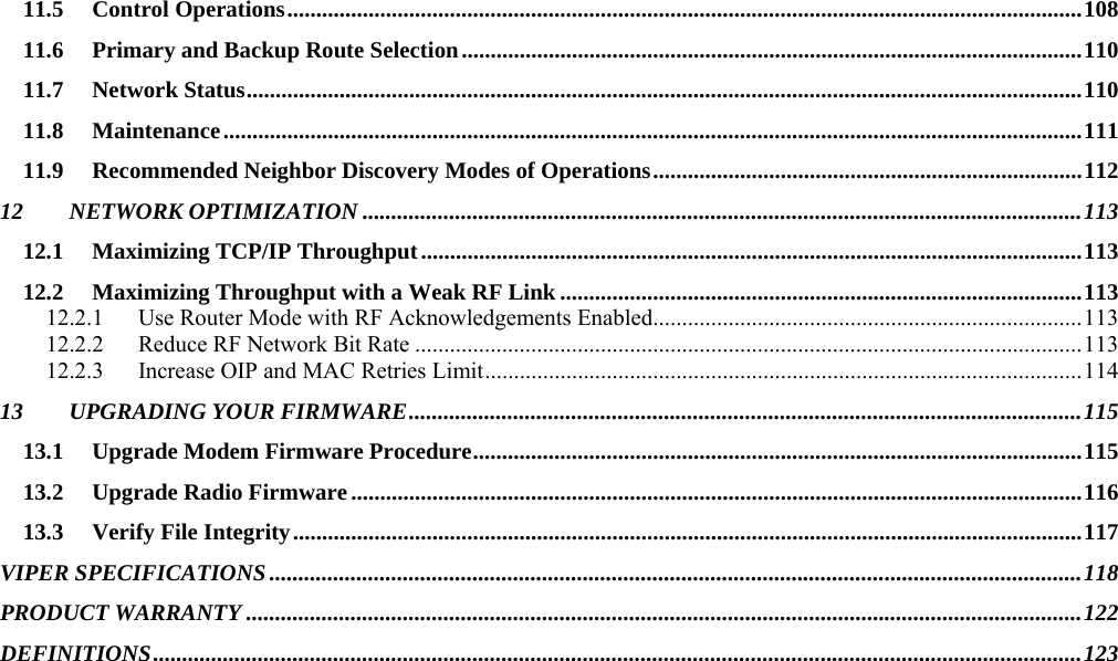
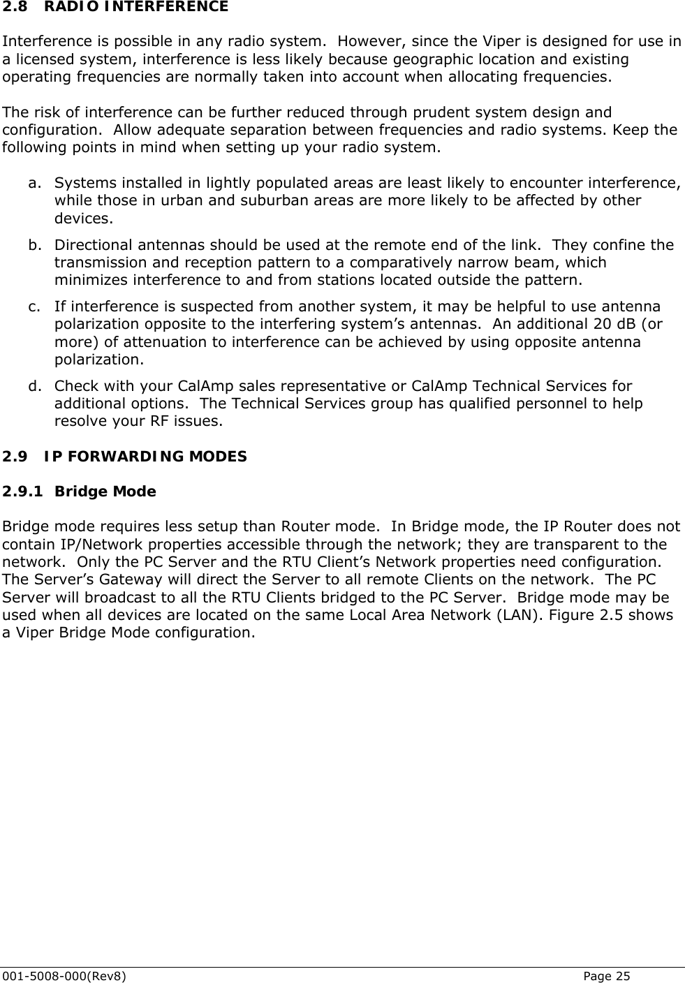
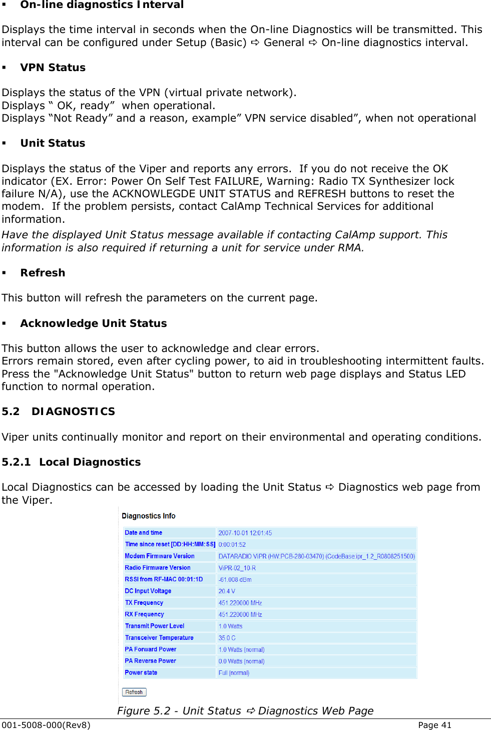
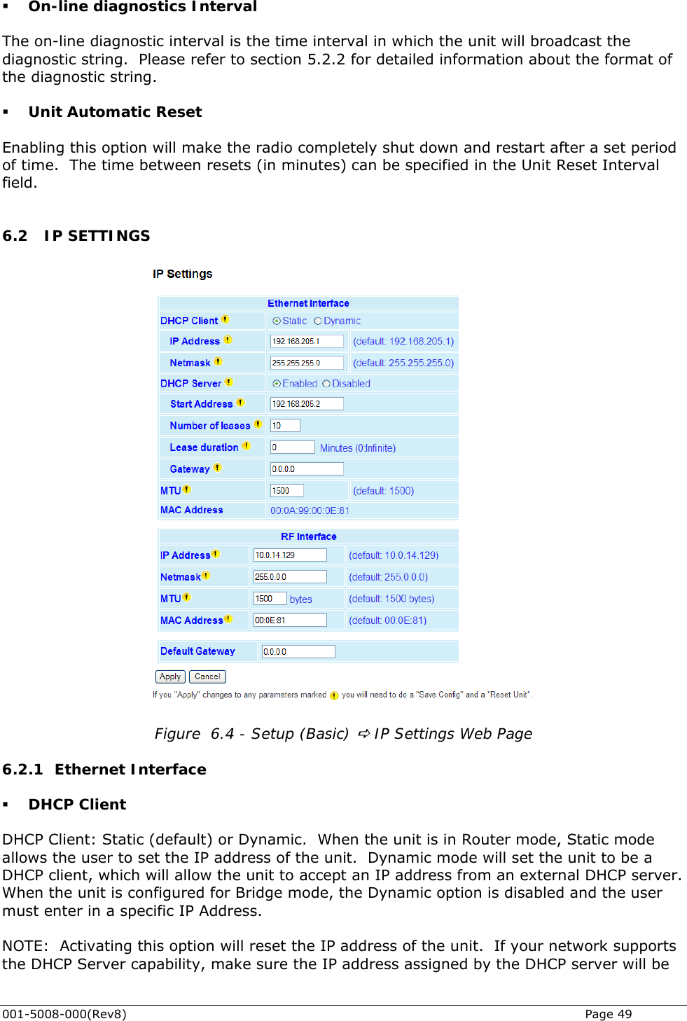
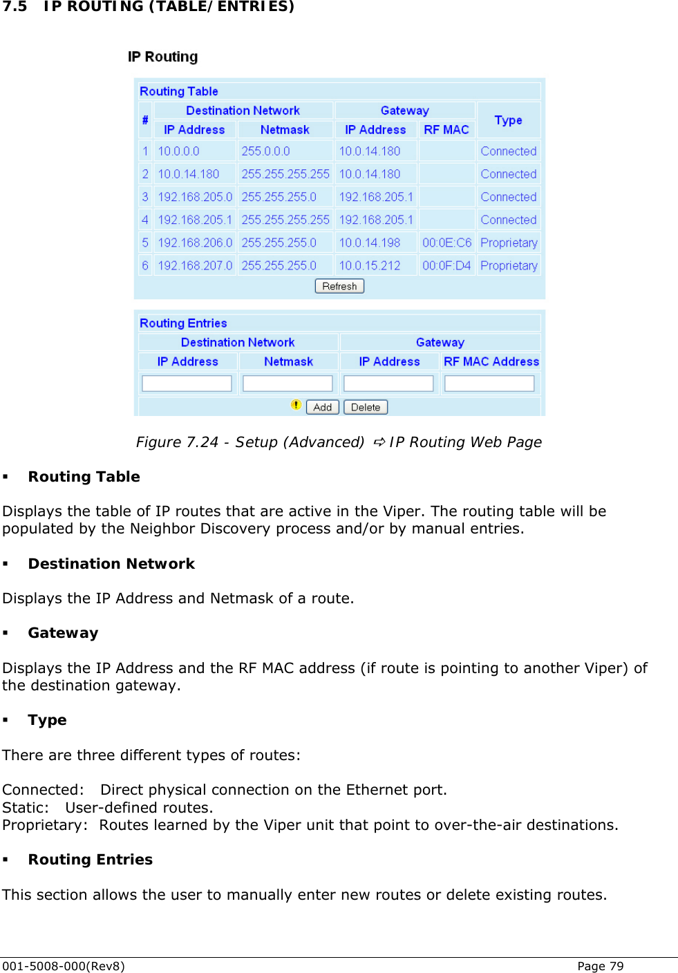
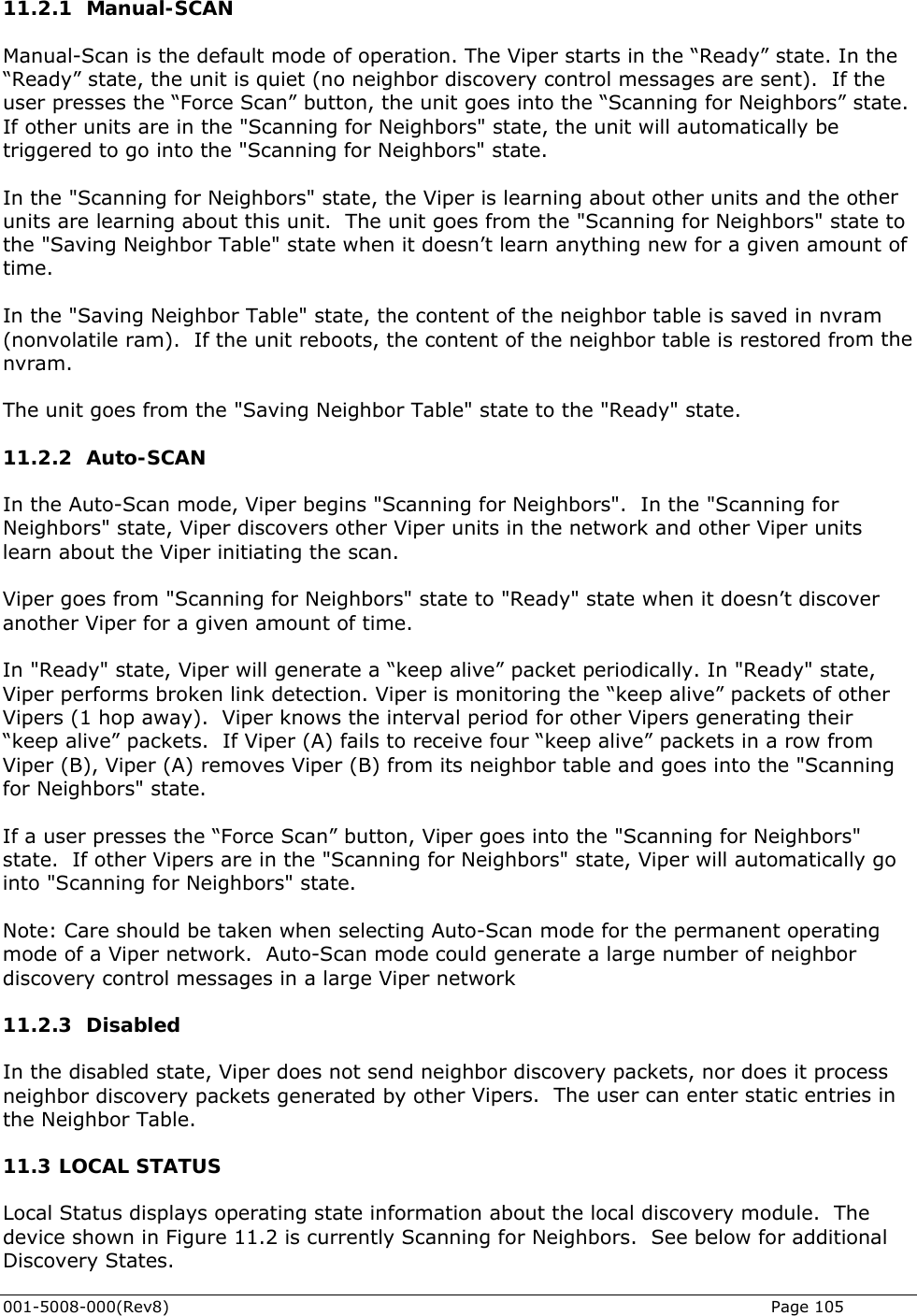
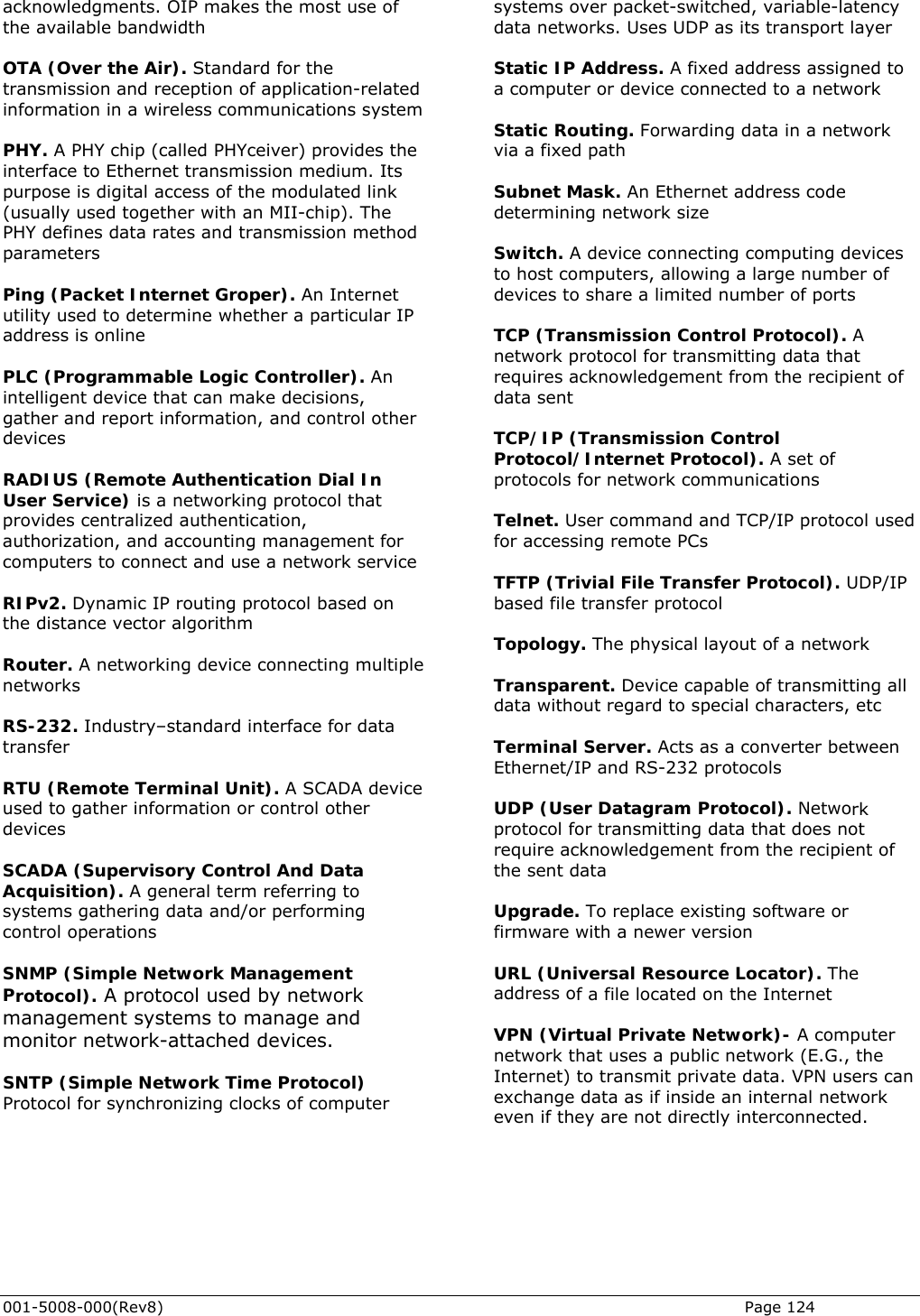
![001-5008-000(Rev8) Page 42 Date and time Displays the time and date. To set the time, an SNTP server must be setup under Setup (Advanced) D Time Source. The SNTP server must also be accessible via the user’s LAN or Internet connection. Time since reset Displays the amount of time since the unit was last reset. [DD,HH,MM,SS], Days, Hours, Minutes, Seconds Modem Firmware Version Displays the modem firmware version of the unit. Radio Firmware Version Displays the radio firmware version of the unit. RSSI from RF-MAC Displays the Received Signal Strength Indication (RSSI) from the unit with the MAC address displayed. The RSSI displayed range is from approximately -50 dBm to -120 dBm. At signal strengths greater than -50 dBm, the radio will still operate but will not display an accurate RSSI value. DC Input Voltage Displays the DC Input Voltage for the unit. TX Frequency Displays the current operating transmit frequency for the active channel. Setup (Basic) D Channel Table D TX RX Frequency Displays the current operating receiver frequency for the active channel. Setup (Basic) D Channel Table D RX Transmit Power Level Displays the programmed power level for the active channel. Setup (Basic) D Channel Table D PA Power Transceiver Temperature Displays the transceiver’s internal temperature in Celsius or Fahrenheit. Setup (Advanced) D User Settings PA Forward Power Displays the actual measured forward power of the transmitter. If the measured forward power drops 1 dB or more below the user configured power level, this line will report “(fault)”. When the forward power is within range, this line will report “(normal)”. The Viper radio can be configured to send an SNMP trap (or alarm) if the Forward Power goes into a “fault” state.](https://usermanual.wiki/CalAmp-Wireless-Networks/5098-502/User-Guide-1328627-Page-42.png)