CalAmp Wireless Networks BDD4T85-2 Paragon/PD User Manual 392067

CALAMP WIRELESS NETWORKS INC. Paragon/PD 392067

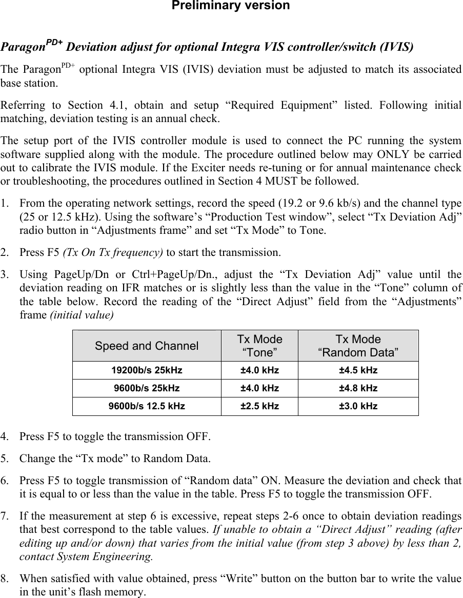
IVIS option technical appendix

Preliminary version  ParagonPD+ Deviation adjust for optional Integra VIS controller/switch (IVIS) The ParagonPD+ optional Integra VIS (IVIS) deviation must be adjusted to match its associated base station.  Referring to Section 4.1, obtain and setup “Required Equipment” listed. Following initial matching, deviation testing is an annual check. The setup port of the IVIS controller module is used to connect the PC running the system software supplied along with the module. The procedure outlined below may ONLY be carried out to calibrate the IVIS module. If the Exciter needs re-tuning or for annual maintenance check or troubleshooting, the procedures outlined in Section 4 MUST be followed.  1. From the operating network settings, record the speed (19.2 or 9.6 kb/s) and the channel type (25 or 12.5 kHz). Using the software’s “Production Test window”, select “Tx Deviation Adj” radio button in “Adjustments frame” and set “Tx Mode” to Tone.    2. Press F5 (Tx On Tx frequency) to start the transmission.  3. Using PageUp/Dn or Ctrl+PageUp/Dn., adjust the “Tx Deviation Adj” value until the deviation reading on IFR matches or is slightly less than the value in the “Tone” column of the table below. Record the reading of the “Direct Adjust” field from the “Adjustments” frame (initial value) Speed and Channel  Tx Mode “Tone” Tx Mode “Random Data” 19200b/s 25kHz   ±4.0 kHz  ±4.5 kHz 9600b/s 25kHz   ±4.0 kHz  ±4.8 kHz 9600b/s 12.5 kHz   ±2.5 kHz  ±3.0 kHz  4. Press F5 to toggle the transmission OFF.  5. Change the “Tx mode” to Random Data. 6. Press F5 to toggle transmission of “Random data” ON. Measure the deviation and check that it is equal to or less than the value in the table. Press F5 to toggle the transmission OFF.  7. If the measurement at step 6 is excessive, repeat steps 2-6 once to obtain deviation readings that best correspond to the table values. If unable to obtain a “Direct Adjust” reading (after editing up and/or down) that varies from the initial value (from step 3 above) by less than 2, contact System Engineering. 8. When satisfied with value obtained, press “Write” button on the button bar to write the value in the unit’s flash memory.

Navigation menu